1. Pergamon
Solar Energy Vol. 58, No. 4-6, pp. 213-217, 1996
PII: SOO38-092X(96)00065-5
Copyright 0 1996 Elsevier Science Ltd
Printed in Great Britain. All rights reserved
0038-092X/96 $15.00+0.00
GAS HEAT CONDUCTION IN AN EVACUATED TUBE
SOLAR COLLECTOR
T. BEIKIRCHER,* G. GOLDEMUND* and N. BENZ**
*Sektion Physik der Ludwig-Maximilians-Universitlt Miinchen, Amalienstr. 54, D-80799 Miinchen,
Germany and **Bayerisches Zentrum ftir angewandte Energieforschung e.V. (ZAE Bayern), Domagkstr.
11, D-80807 Miinchen, Germany
(Communicated by Brian Norton)
Abstract-We investigated experimentally the pressure dependency of the gas heat conduction in an
evacuated plate-in-tube solar collector. A stationary heat loss experiment was built up with an electrically
heated real-size collector model. The gas pressure was varied from 10m3 to 10“ Pa, the temperatures of
the absorber and the casing were held at 150°C (electrical heaters) and 30°C (water cooling), respectively.
Losses by radiation and solid conduction were determined experimentally at pressures below 0.1 Pa. At
higher pressures these background losses were subtracted from the total heat losses, to receive the heat
losses by gas heat conduction. The experimental results were compared with approximative theoretical
models. The onset of convection is in agreement with the usual theories for parallel plates, taking the
largest distance between the absorber and the glass tube as the plate distance. As a first approximation
the pressure dependency of the gas heat conduction is described by the usual theory for parallel plates,
taking the smallest distance between the absorber and the glass tube as the plate distance. Copyright 0
1996 Elsevier Science Ltd.
1. INTRODUCTION
Tube collectors (ETCs) generally consist of an
evacuated glass tube containing the solar
absorber. The latter is mostly a centered, selec-
tively coated metallic flat plate (plate-in-tube
collector) (Frei, 1993) or a concentric glass tube,
which is selectively coated at its outer side (tube-
in-tube) collector (Harding et al. 1985). The
vacuum is maintained by means of a chemical
adsorption pump (getter). Typical inner pres-
sures are between 10Y2 and 10-l Pa (Frei,
1993), which is in the transition between the
continuum range (thermal conductivity 2 inde-
pendent of pressure p) and the free molecular
range (A-P). However, even at these low pres-
sures, the gas heat conduction may be not
totally suppressed. Despite the use of chemical
getters, the gas pressure can still increase during
the lifetime of the collector as a result of leaks,
desorption from the hot selective layer (Window
and Harding 1984) or diffusion of gases (especi-
ally Helium) from the atmosphere through the
glass tube (Harding, 1981a). In addition the
capacity of the chemical getter is limited. As a
consequence, the losses of the ETC are aug-
mented and knowledge of the pressure depen-
dency of the gas heat conduction in the
transition range becomes important. The gas
heat conduction in tube-in-tube collectors has
been examined in two works. Harding and
Window (1981b) theoretically investigated the
gas heat conduction in the free molecular range.
O’Shea and Collins (1992) experimentally inves-
tigated the gas heat transfer in the transition
range. For the plate-in-tube collector no compa-
rable works have been known so far. No theoret-
ical model exists and also experimental data in
the transition range are not available.
2. EXPERIMENTAL SETUP
Losses by gas heat conduction are determined
by measuring the heat losses of the absorber
plate for varying interior gas pressures. The
experiments have been carried out with pressures
ranging from 10e2 to lo4 Pa. A diagram of the
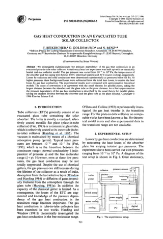
test setup is shown in Fig. 1. Once stationary,
-T
ZL 1
power supply
I ‘-I
scanner
I ’
PC -
digital
IEEE multimeter
Fig. 1. The experimental setup.
213
2. 214 T. Beikircher et al.
the electrical power P,, necessary to keep the
absorber at a certain temperature equals the
total heat loss power, consisting of solid conduc-
tion P,, (suspension of the absorber), radiation
P rad 7 and gas heat conduction power P,:
Pel=Psc+Prad+Pgc~ (1)
In order to determine P, from eqn (l), the
values of the background losses, Pbg= P,, + Prad
must be known. Pbg is experimentally deter-
mined at pressures below 0.01 Pa, where gas
heat conduction is suppressed almost com-
pletely. At higher pressures P, is obtained by
Pgc=Pel-Pbg* (2)
The loss coefficient by gas heat conduction, kgc,
is defined by
(3)
Here Tabs and Tghss are the temperatures of the
absorber and the glass tube, respectively.
We built up a real-size model of an evacuated
plate-in-tube collector (technical data in the
appendix) (Goldemund, 1995). The absorber
plate (uncovered aluminum) was equipped with
controllable electrical heaters to simulate the
absorption of solar radiation. The temperatures
of the absorber plate and the glass tube were
measured by 10 thermocouple sensors (absorber
plate) and 4 platinum resistance sensors (glass
tube). The error of measurement was less than
0.2 K for the single sensor and less than 2 K for
the mean temperatures of the different areas.
The latter value results from the spatial inhomo-
geneity of the temperature and the finite number
of sensors. By regulation of the heating power,
the absorber temperature was held at a constant
level of 150f 0.2”C during all experiments. The
error of the power measurement was 2%. The
interior gas pressure was measured by four
different sensors: an ionization vacuum meter
for pressures below 1 Pa (error + lOO%, - 50%),
a thermal conductivity vacuum gauge for the
range 1 to 10 Pa (error less than 25%), and two
capacitive instruments for pressures between 10
and 1000 Pa (error 0.2 Pa +0.6%) and lo3 to
lo5 Pa (error: 40 Paf0.7%). Different values of
the interior pressure were adjusted and sus-
tained by means of a turbo molecular pump
(pressures below 1 Pa), a rotary switch pump
(pressures below lo3 Pa) and a diaphragm
pump (pressures above lo3 Pa). In steady state
all temperatures, the electrical heating power,
and the interior pressure were recorded with a
frequency of 0.02 Hz over a period of at least 1 h.
3. EXPERIMENTAL RESULTS
Figure 2 shows the experimental results for
P,i(p) together with the margin of error. The
error in the background losses (4%) is also
included. The results are: (i) The pressure limit
for the onset of convection is about 5000 Pa.
(ii) Between 5000 Pa and 100 Pa is the contin-
uum range, i.e., the gas heat conduction is
independent of pressure. (iii) Gas heat conduc-
tion losses decrease below 100 Pa. (iv) At 0.1 Pa
the gas conductive losses are suppressed totally
(below the error of measurement). (v) Solid
conduction and radiation losses amount to
about 40 W and form about one half of the
losses by gas heat conduction in the continuum.
(This portion may decrease in a real collector
with heat removal by a fluid). These background
losses are mainly caused by radiation, because
a theoretical estimation of the solid conduction
losses caused by the absorber suspension, the
leads and the heating wires totally gave values
below 5 W (Goldemund, 1995).
However, numerical calculations of the gas
heat conduction in the continuum range
(Goldemund, 1995) yield values that are about
13% lower than the experimental gas heat con-
duction loss power P,. This discrepancy results
from gas heat conduction caused by the hot
components leads, heating-wires and absorber
suspension. The pressure dependency of these
shunt losses can be hardly calculated, but may
influence the pressure dependency of the total
gas heat conduction.
4. COMPARISON WITH THEORY,
DISCUSSION
As we know, there is no theory of convection
for a centered hot plate in a cylinder. Therefore,
as an approximation we use known formulas
for the case of parallel plates: here, the onset of
convection takes place if the Rayleigh number
Ra exceeds a certain critical value Ru,,
Ra=
gp2c,D3M2 AT
/doR2T3
2 1708 = Racr (4)
9.81 m/s2
with (for air)
g=
cp =
AT=
p=
& =
R=
T=
M=
1.005 kJ/kg/K, specific heat capacity,
120 K, temperature difference,
2.2. 10e5 Ns/m2, dynamic viscosity,
0.0305 W/m/K, thermal conductivity,
8.31 J/mol/K, universal gas constant,
363 K, mean gas temperature,
28.8 kg/mol, molar mass.
3. Gas heat conduction in an evacuated tube solar collector
140 __
I
0.1 1 10 100 1000 104
Pressure in [Pal
Fig. 2. Experimentally determined total heat loss power versus inner pressure.
215
From (4) follows the critical pressure per
which yields that a greater D corresponds to a
lower per. Consequently taking the largest dis-
tance between the absorber and the glass tube
(5 cm) as the plate distance, D, per is theoretically
obtained:
per= 5550 Pa.
There is good agreement with the experimen-
tally determined onset of convection at about
5000 Pa.
Gas heat conduction is experimentally inde-
pendent from pressure p for p> 100 Pa. From
kinetic gas theory, this independence holds for
Kn~0.01 (Saxena and Joshi, 1989), where the
Knudsen number Kn is defined as the ratio
between the mean free path ifreeand the typical
distance dchar of the gas heat transport process:
Kn: =Ifrcc.
dchar
In the case of air the mean free path empirically
is (Verein Deutscher Ingenieure, 1988):
1 8,313. 10W3m
lfree = - *
p 1+116K/T’
(7)
The mean temperature T of the air is 363 K
in the experiment. In the collector investigated,
the typical distance of the gas heat transport
(distance absorber-glass tube) ranges between
5 mm and 5 cm. According to eqns (6) and (7),
the onset of reduction of the gas heat conduction
is determined by the smallest typical distance,
i.e. 5 mm: The condition Kn=O.Ol is met at
126 Pa, in agreement with the experiment.
Between 100 and 0.1 Pa gas heat conduction
is reduced strongly with decreasing pressure. So
far, no theory of this pressure dependency exists
for the geometry of a plate-in-tube collector.
For parallel plates, however, there is a well
known relation for the pressure dependent heat
loss power P,Jp) by gas heat conduction
(Kennard, 1938), which for air reads:
P gc.0
P,(p)= .
1+$L
(8)
Here pgc,ois the gas heat conduction loss
power in the continuum, and it is assumed that
the air at the wall totally accommodates to wall
temperature. Now, for the plate-in-tube collec-
tor one can calculate two limiting cases of
eqn (8), using 5 mm and 5 cm as the typical
distance in Kn. To obtain Pgc,o for our tube
collector model, we thereby used the exper-
imentally determined mean value for
P,,( 100 Pa <p < 5000 Pa), i.e., the total heat loss
power in the continuum range, and subtracted
P bg, i.e. the losses by radiation and solid
conduction.
In Fig. 3, we compare experimental and theo-
retical values for the total heat loss power. The
theoretical results are obtained by calculating
4. 216 T. Beikircher et al.
0.1 1 10' 100 1000
Pressure in [Pal
Fig. 3. Experimental results versus theoretical results for the pressure dependent total heat loss power of
the collector model. The theoretical values were obtained using eq. (8) for the loss power by gas heat
conduction and adding the experimental loss power at pi 0.1 Pa for radiation and solid conduction. The
typical distance of the gas heat conduction in eq. (8) was set to the lowest (5 mm) and highest (5 cm)
separation between the glass tube and the absorber plate, respectively.
P,,(p) according to eqn (8) and adding the
experimentally determined Pbg. Obviously the
experimental data is described closer by setting
the plate distance to the lowest possible value
of 5 mm. However, it must be remembered that
the absorber plate of our collector model has
an extraordinary height of 7 mm compared with
commercial absorber plates. As a consequence,
the percentage of the losses via the smallest
distance between the absorber plate and the
glass tube is certainly higher than in a collector
with a thinner absorber plate.
Summarizing, the pressure dependency of the
gas heat conduction is described nearly correctly
within the experimental error bars by the for-
mula for parallel plates, with the lowest distance
between the absorber plate and the glass tube
as the characteristic length of the gas heat
conduction. It should be emphasized, however,
that the described shunt losses by gas heat
conduction may in an incontrollable way adul-
terate the experimental pressure dependency
and that also the error in pressure measurement
below 2 Pa is large.
5. OUTLOOK
It is planned to install counter-heaters at the
margin of the absorber plate, to eliminate the
described shunt losses. In addition, the pressure
measurement should be refined: with capacitive
sensors the error of measurement can be reduced
to only a few percent also in the low pressure
range. Also, it can be tried to solve the
Boltzmann transport equation or to apply
Kennard’s temperature jump method, to get
results for an arbitrary plate-in-tube collector
geometry. It may be interesting to use heat-
insulating filling gases at moderate vacua, as
proposed for evacuated flat-plate solar collec-
tors (Beikircher et al., 1995), also for ETCs.
Firstly, a simpler and cheaper tightening tech-
nique could be used. Secondly, if the pressure
increases, for example by leaks, such a configu-
ration would have the better mean efficiency
over the lifetime with respect to an originally
highly evacuated ETC.
6. CONCLUSION
A stationary heat loss experiment with a
plate-in-tube collector model was built up. The
pressure dependency of thermal losses was mea-
sured between 0.01 and lo4 Pa at absorber
temperatures of 150°C. The experiments yield
the following results. (i) Inner pressures below
0.1 Pa are sufficient to efficiently suppress gas
heat conduction. (ii) If the pressure exceeds
100 Pa, gas heat conduction losses are about
two times as large as the losses by radiation
and solid conduction. (iii) In a first approxima-
tion, the gas heat losses can be described by
5. Gas heat conduction in an evacuated tube solar collector 217
well known formulae for parallel plates. The analysis and reduction. ASME J. Solar Energy Engineer-
plate distance must be appropriately chosen
ing,117.
between the minimum and the maximum dis-
Frei U. (1993) Leistungsdaten thermischer Sonnenkollektoren.
Technical Report, Solarenergie Priif- und Forschungss-
tance of the absorber plate to the glass tube. telle, Technikum Rapperswil, Schweizerisches Bunde-
samt fur Energiewirtschaft BEW.
7. NOMENCLATURE
specific heat capacity at constant pressure (kJ/( kg K))
distance (m)
distance between parallel plates (m)
9.8 1 (m/s*)
Knudsen number
thermal conductivity (W/(m K))
mean free path (m)
molecular mass (kg/mole)
dynamic viscosity (N s/m’)
heat loss power (W)
gas pressure (Pa)
universal gas constant
Rayleigh number (1)
mean gas temperature (K)
Subscripts
abs
bg
char
cr
el
class
8C
rad
SC
0
absorber plate
background
characteristic
critical
electric
glass tube
gas heat conduction
radiation
solid conduction
referred to continuum range
REFERENCES
Beikircher T., Benz N. and Spirkl W. (August 1995). Gas
heat conduction in evacuated flat-plate solar collectors:
Goldemund G. (April 1995) Gaswarmeleitung und Warm-
estrahlung in einem Vakuumrohrenkollektor. Master’s
thesis, LMU Miinchen, Sektion Physik, Prof. Dr. A.
Schenzle.
Harding G. L. (1981a) Helium penetration in all-glass tubu-
lar evacuated solar energy collectors. Sol. Energy Mater.,
5, 141-147.
Harding G. L. and Window B. (1981b) Free molecule ther-
mal conduction in concentric tubular solar collectors.
Sol. Energy Mater., 4, 265-278.
Harding G. L., Zhiqiang Y. Z. and Mackey D. W. (1985)
Heat extraction efficiency of a concentric glass tubular
evacuated collector. Solar Energy, 35(l), 71-70.
Kennard E. H. (1938) Kinetic Theory of Gases. McGraw-
Hill International Book Company, New York.
Saxena S. C. and Joshi R. K. (1989) Thermal Accomodation
and Adsorption CoefJicients of Gases. Hemisphere Pub-
lishing Company, New York.
O’Shea S. J. and Collins R. E. (1992) An experimental study
of conduction heat transfer in rarefied polyatomic gases.
J. Heat Mass Transfer, 35( 12), 3431-3440.
Verein Deutscher Ingenieure (1988). VDI Wiirmeatlas.Verlag
des Vereins Deutscher Ingenieure, Dusseldorf.
Window B. and Harding G. L. (1984). Progress in the
materials science of all-glass evacuated collectors. Solar
Energy, 32( 5), 609-623.
APPENDIX: TECHNICAL DATA OF THE
COLLECTOR MODEL
The evacuated plate-in-tube collector model is briefly
characterized by the following properties:
-glass tube: length 1500 mm, diameter 110 mm, thickness
5 mm,
-absorber: aluminum, length 1450 mm, width 100 mm,
thickness 7 mm, centered in the glass cylinder.
The author has requested enhancement of the downloaded file. All in-text references underlined in blue are linked to publications on ReseaThe author has requested enhancement of the downloaded file. All in-text references underlined in blue are linked to publications on Resea