This document discusses the analysis of balanced and unbalanced faults in power systems. It introduces balanced three-phase faults and various types of unbalanced faults. The key aspects covered include:
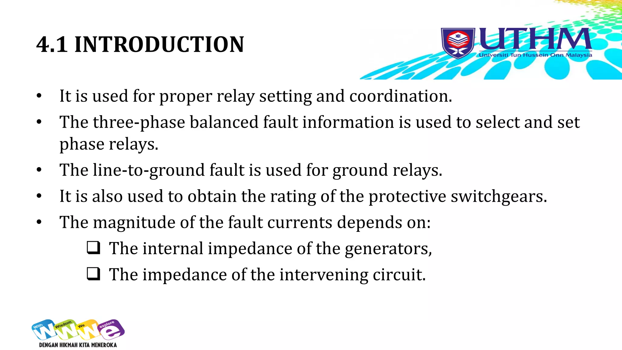
- Determining bus voltages and line currents during different fault types for protection and rating equipment.
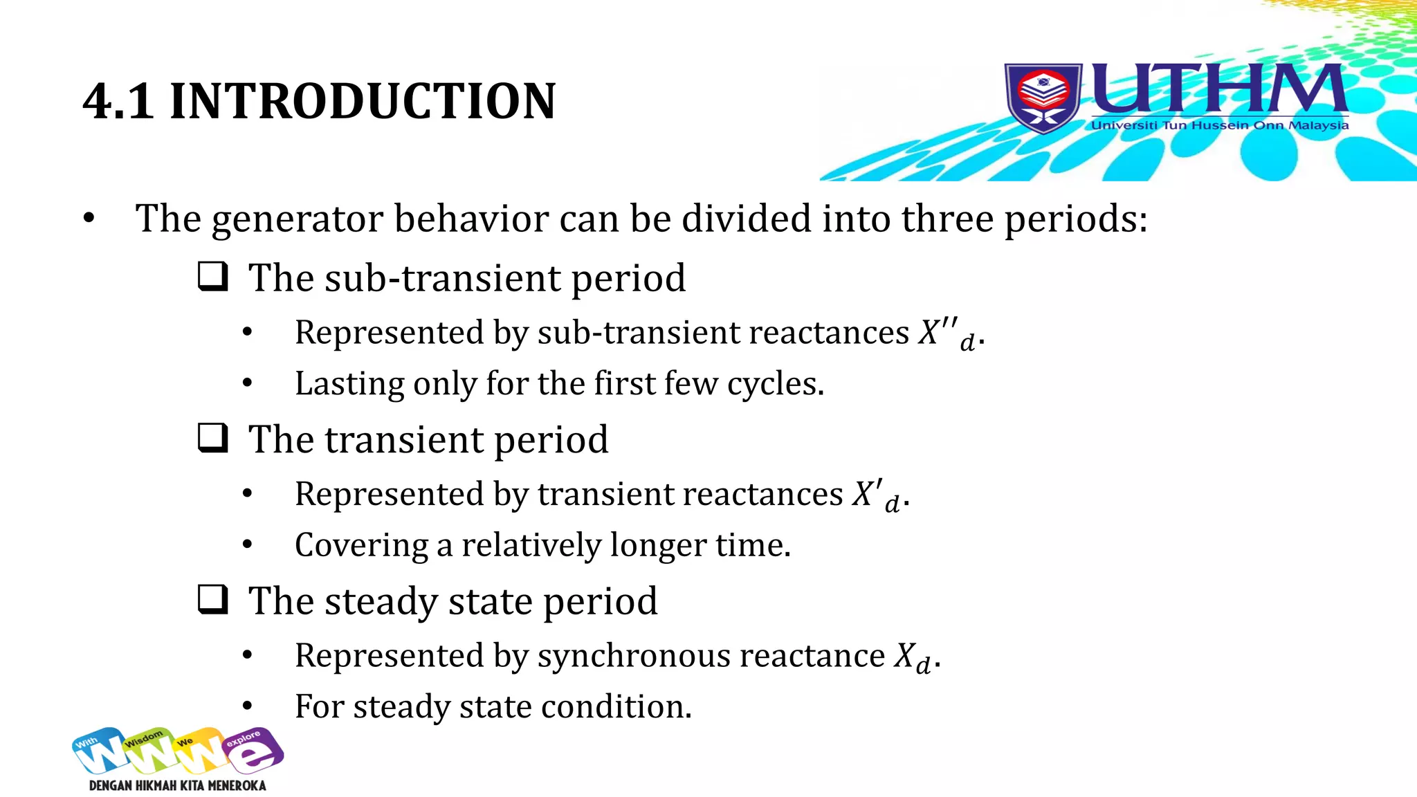
- Generator behavior during sub-transient, transient, and steady-state periods of a fault.
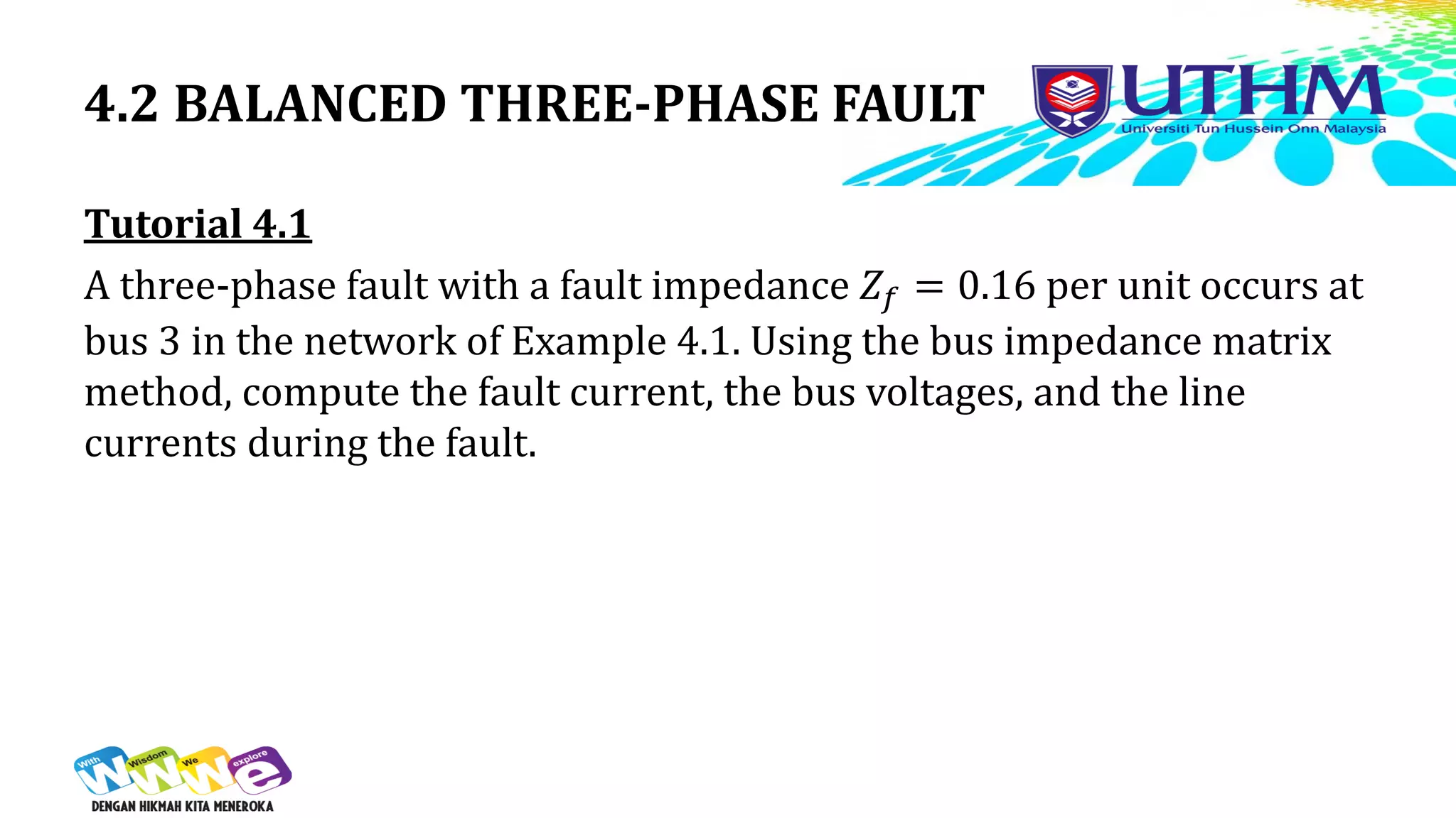
- Calculating fault current, bus voltages, and line currents using bus impedance matrix methods for examples of three-phase faults on different buses.
- Definitions and calculations related to short-circuit capacity and symmetrical components analysis for unbalanced faults.
![4.2 BALANCED THREE-PHASE FAULT
Example 4.1 Determine the fault current, the
bus voltages, and the line currents
during the fault when a balanced
three-phase fault with a fault
impedance 𝑍_𝑓= 0.16 per unit
occurs on:
a) Bus 3 [-j2.0 pu, -j0.1 pu, -j1.1 pu, -
j0.9 pu],
b) Bus 2 [-j2.5 pu, -j0.5 pu, -j0.5 pu, -
j0.5 pu],
c) Bus 1 [j3.125 pu, j3.125 pu, -j3.125
pu, -j3.125 pu].
Figure 1](https://image.slidesharecdn.com/bef43303-201620171w4-230622142535-a9f115b4/75/BEF43303_-_201620171_W4-Analysis-of-Balance-and-Unbalance-Fault-pdf-8-2048.jpg)

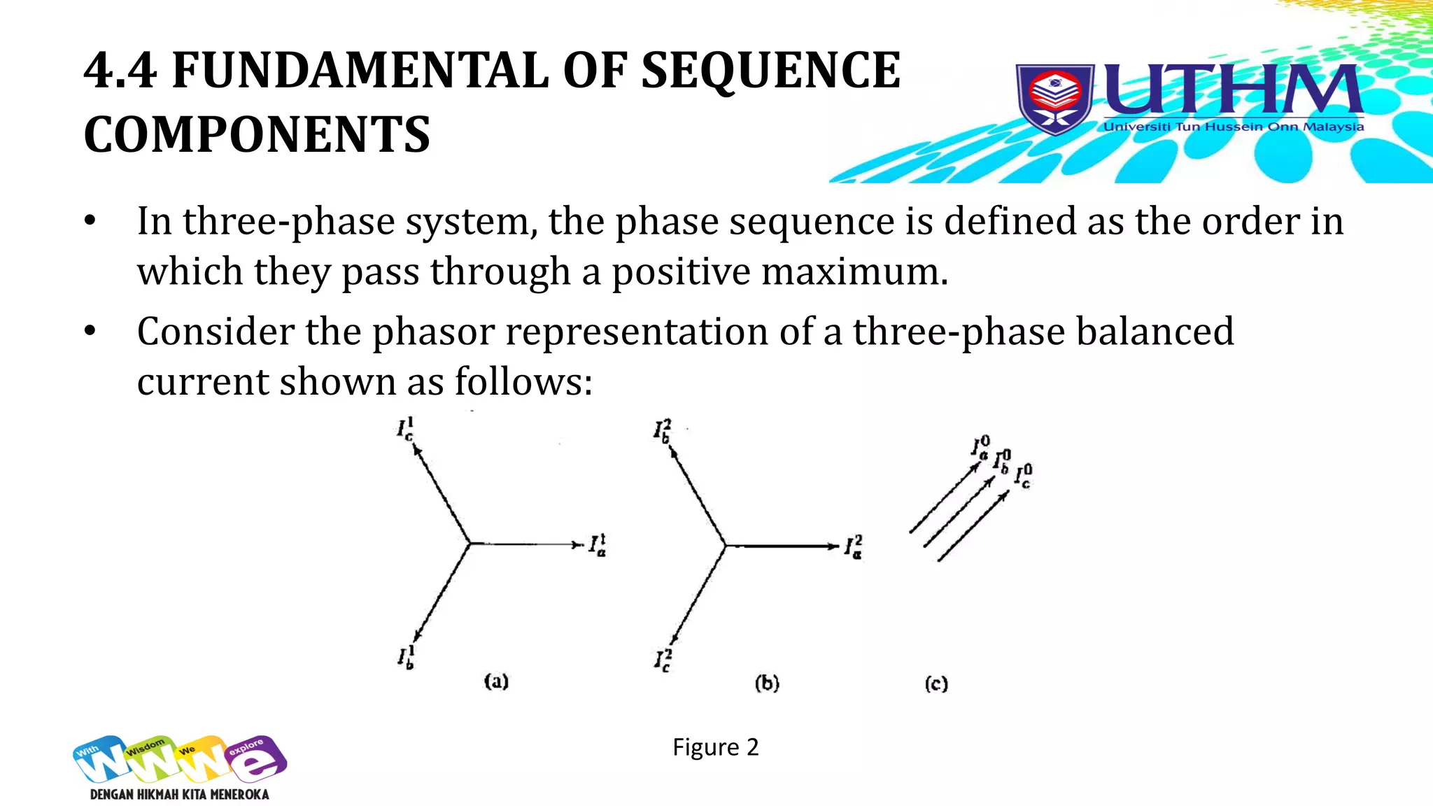

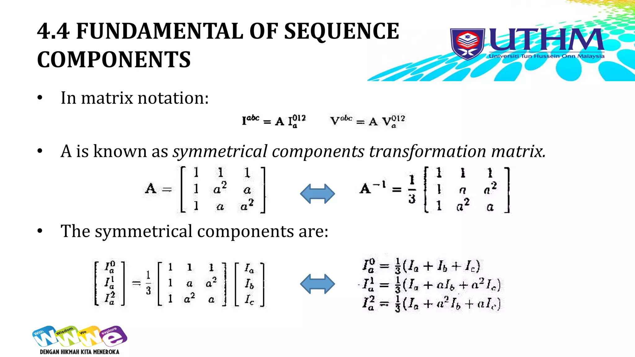
![4.4 FUNDAMENTAL OF SEQUENCE
COMPONENTS
Example 4.3
Obtain the symmetrical components of a set of unbalanced currents
𝐼𝑎 = 1.6∠25°, 𝐼𝑏 = 1.0∠180°, and 𝐼𝑐 = 0.9∠132°.
[0.4512∠96.4529°
,0.9435∠ −0.0550°
,0.6024∠22.3157°
].](https://image.slidesharecdn.com/bef43303-201620171w4-230622142535-a9f115b4/75/BEF43303_-_201620171_W4-Analysis-of-Balance-and-Unbalance-Fault-pdf-21-2048.jpg)
![4.4 FUNDAMENTAL OF SEQUENCE
COMPONENTS
Example 4.4
The symmetrical components of a set of unbalanced three-phase
voltages are 𝑉
𝑎
0 = 0.6∠90°, 𝑉
𝑎
2 = 1.0∠30°, and 𝑉
𝑎
1 = 0.8∠ −30°. Obtain
the original unbalanced phasors.
Obtain the symmetrical components of a set of unbalanced currents
𝐼𝑎 = 1.6∠25°, 𝐼𝑏 = 1.0∠180°, and 𝐼𝑐 = 0.9∠132°. [1.7088∠24.1825°
,
0.400∠90.0000°
, 1.7088∠155.8175°
].](https://image.slidesharecdn.com/bef43303-201620171w4-230622142535-a9f115b4/75/BEF43303_-_201620171_W4-Analysis-of-Balance-and-Unbalance-Fault-pdf-22-2048.jpg)


