- Any abnormal condition that causes excessive current flow through unintended paths in a power system is defined as a fault.
- Faults can be caused by insulation failures, lightning strikes, or accidental operations and must be safely disconnected to prevent equipment damage.
- Short circuit current calculations are required to select properly rated circuit breakers and relay settings for protection schemes.
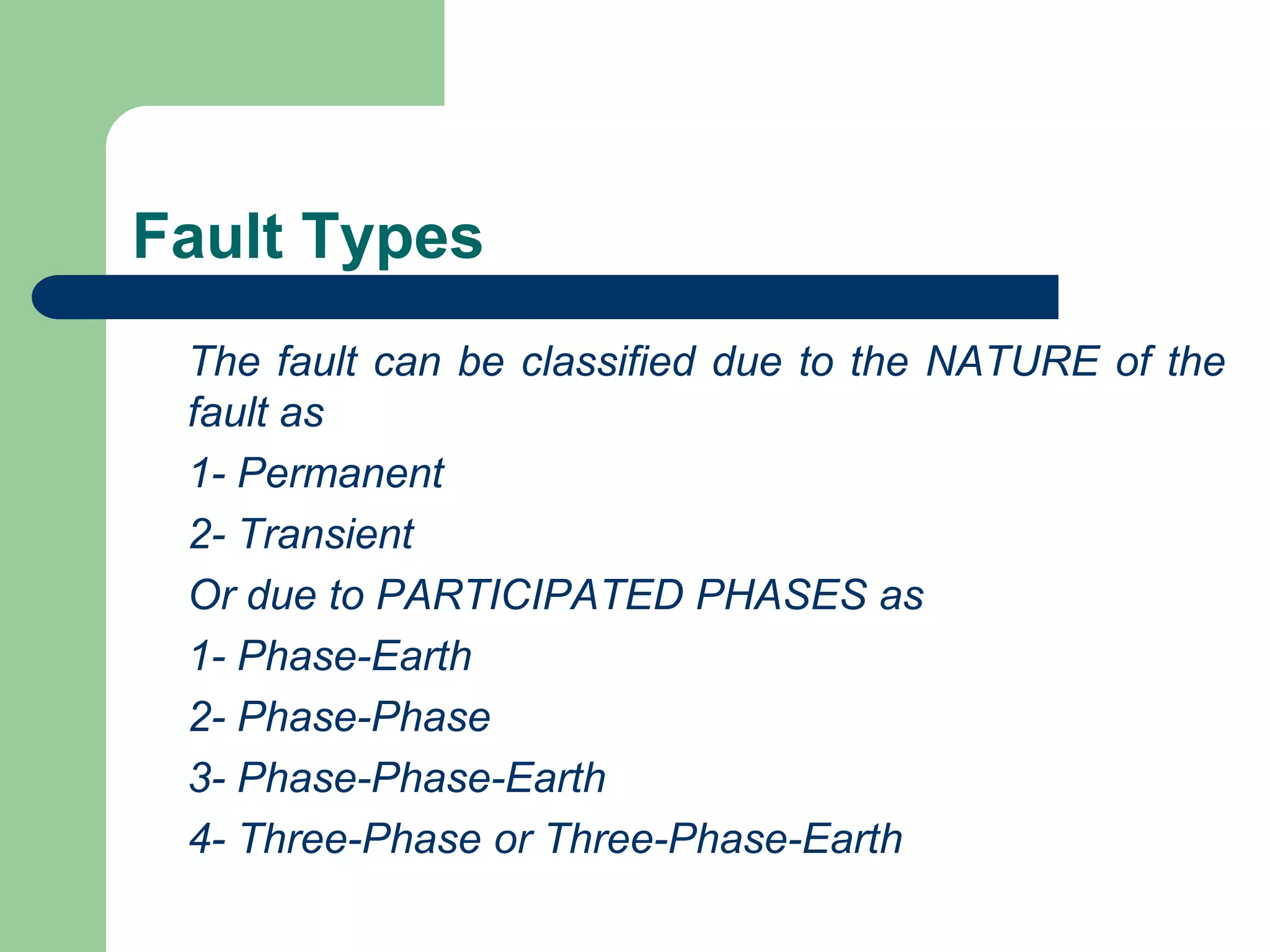
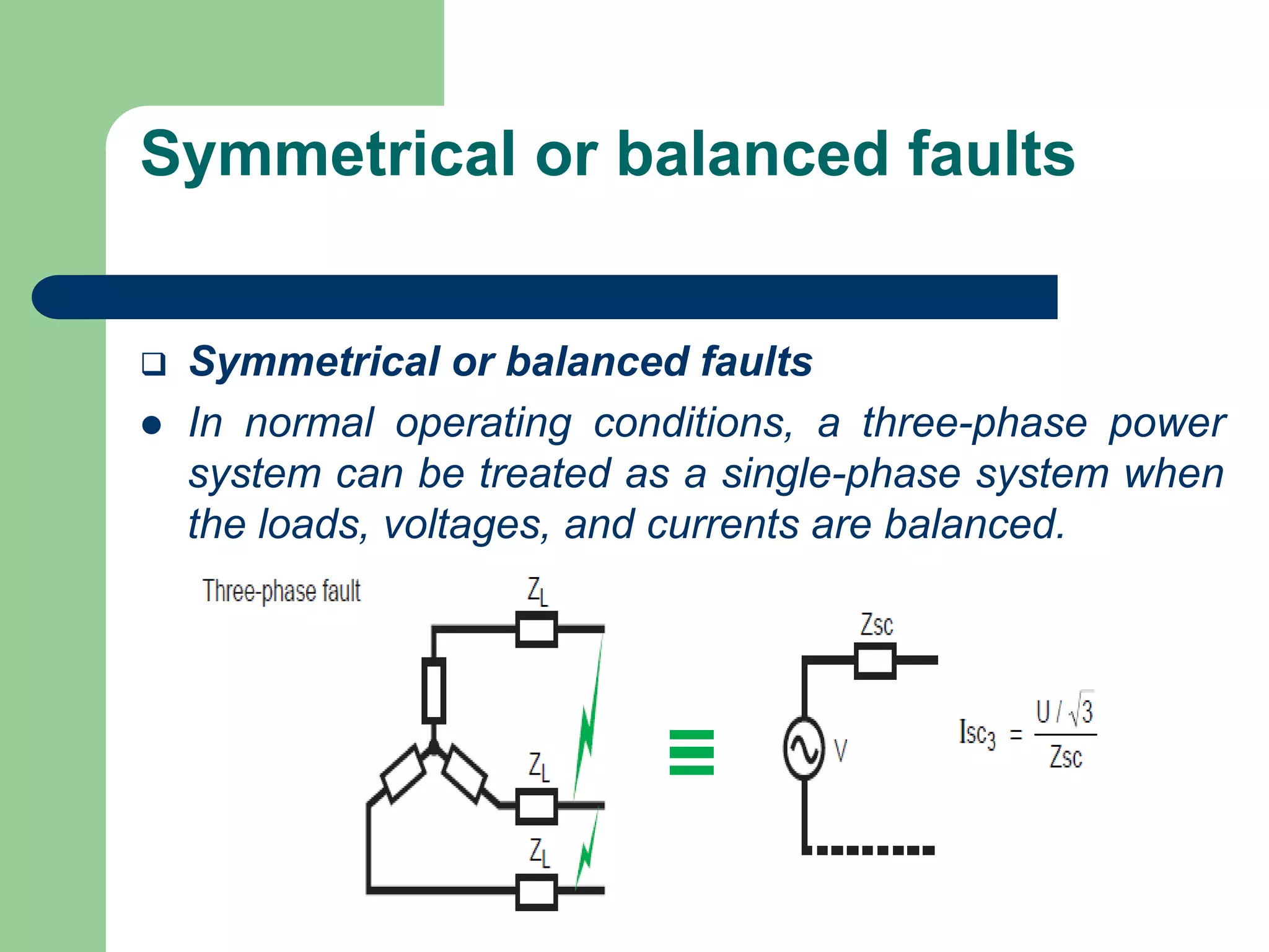
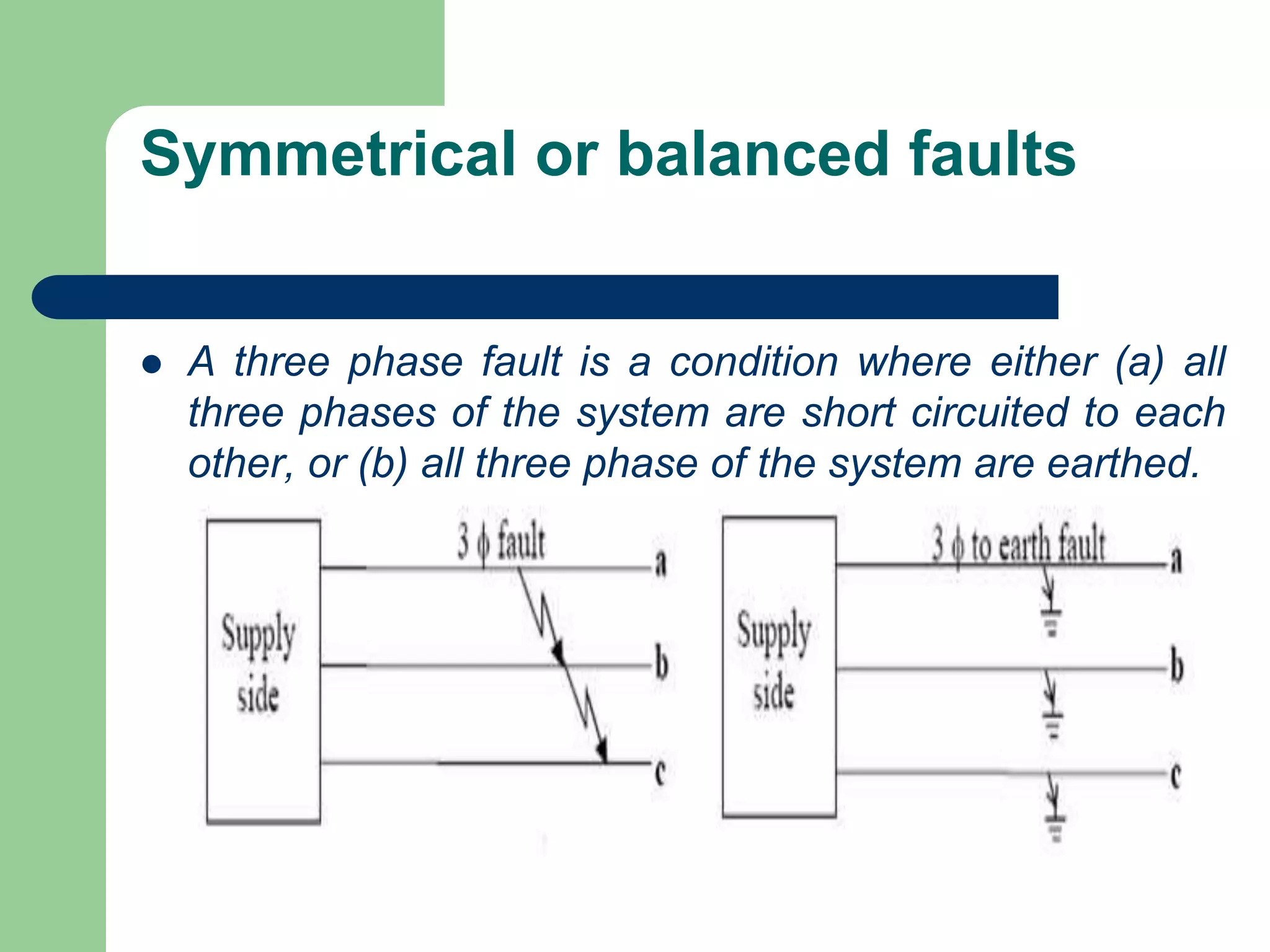
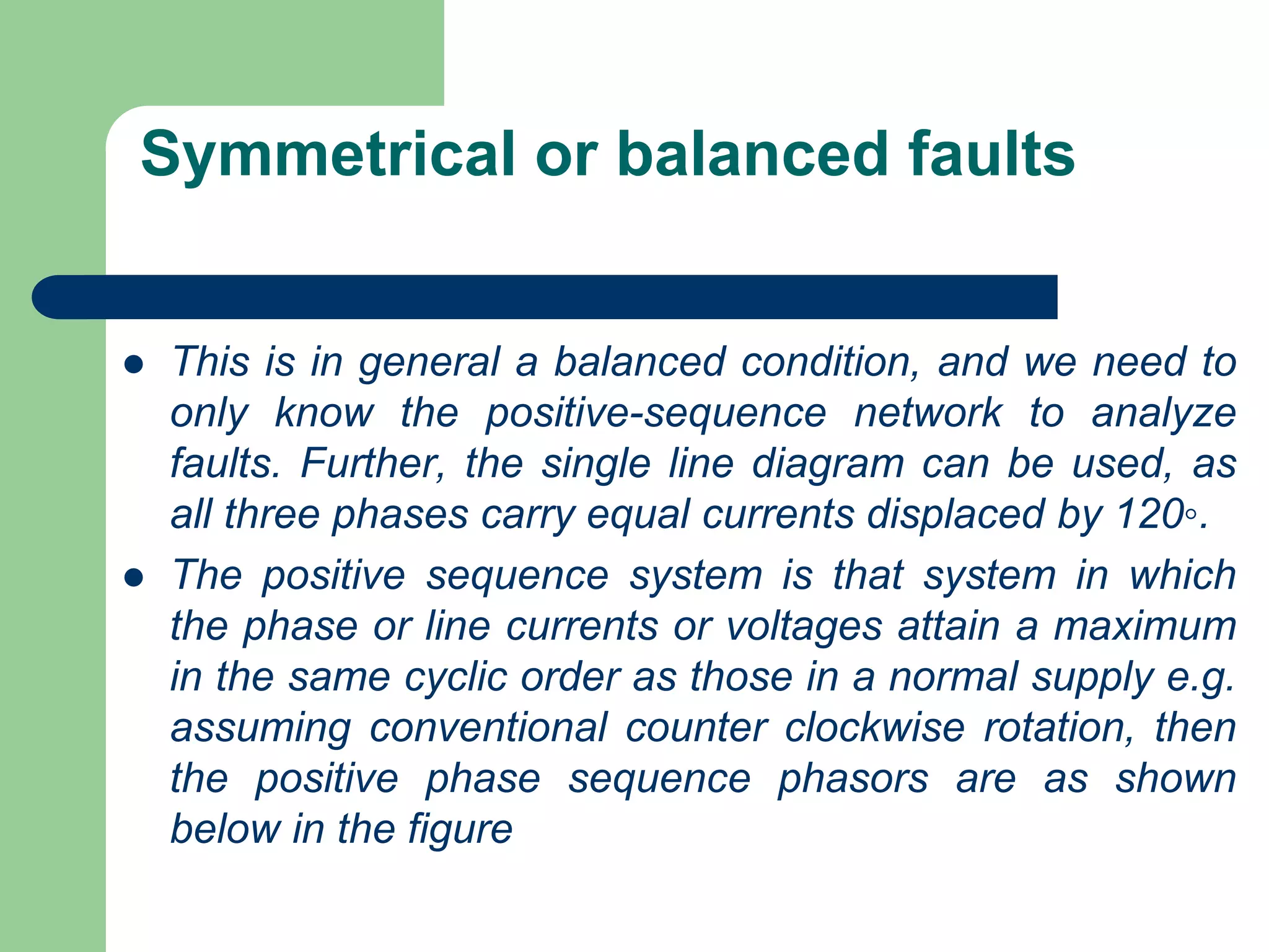
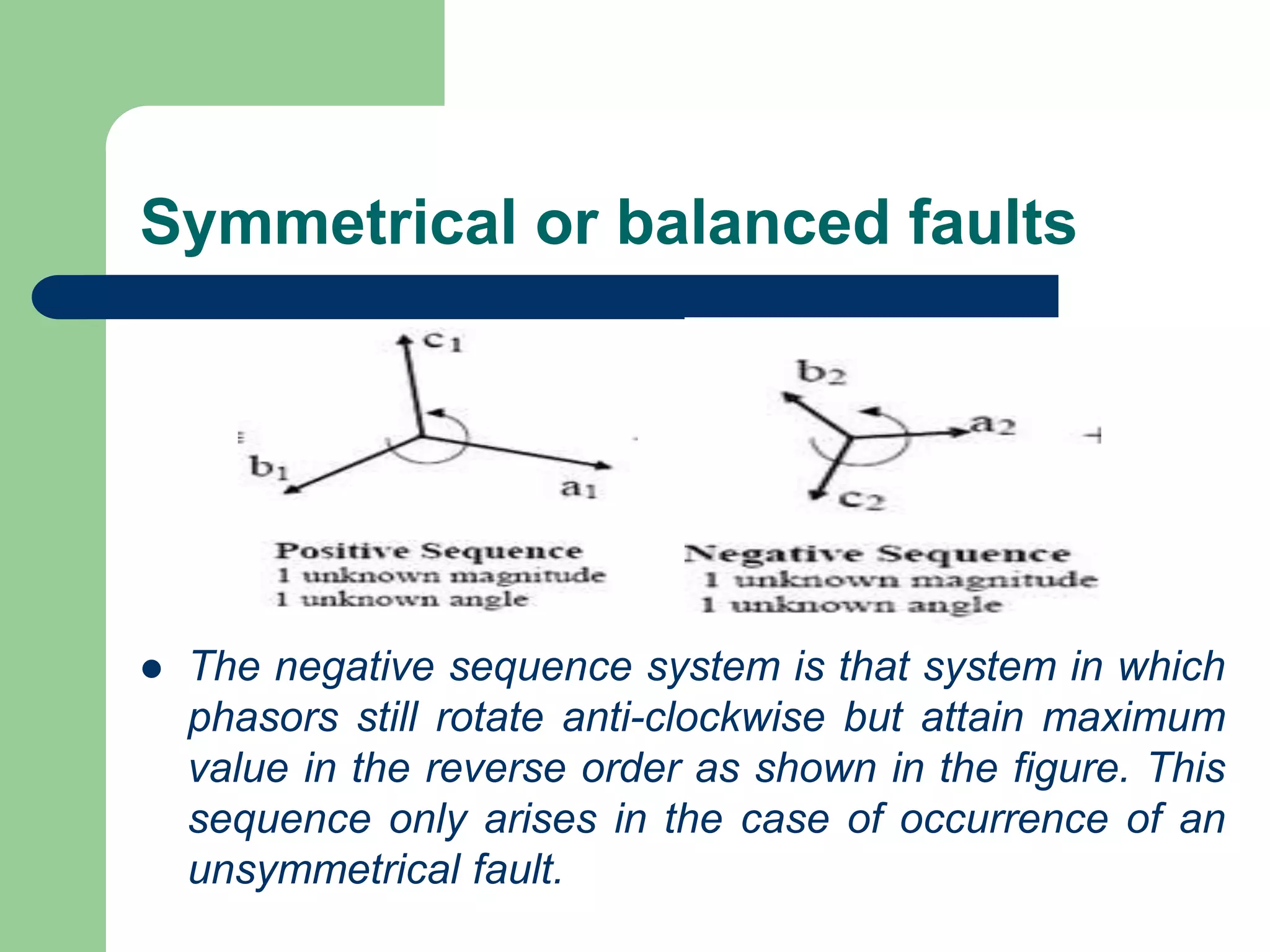
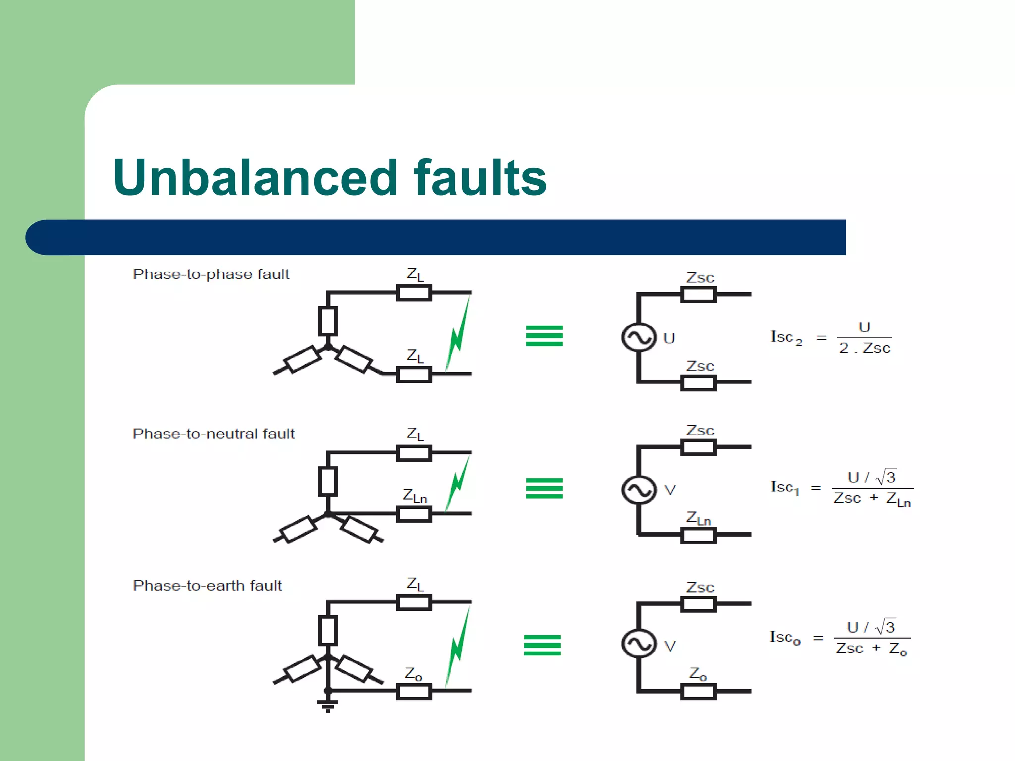
- Faults are classified by nature, participating phases, and whether they are symmetrical or asymmetrical. Symmetrical faults can be analyzed using positive sequence networks while unsymmetrical faults require symmetrical component analysis.
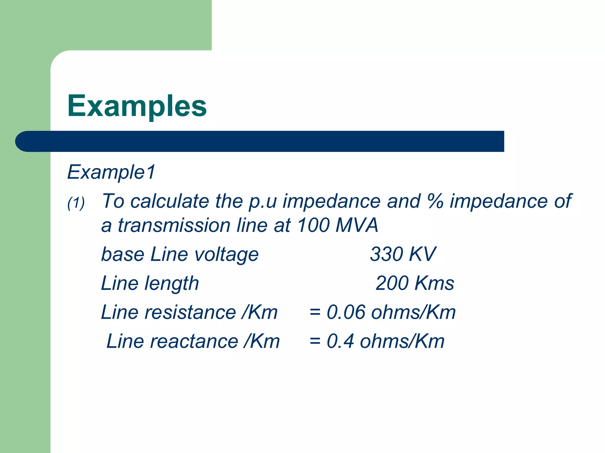
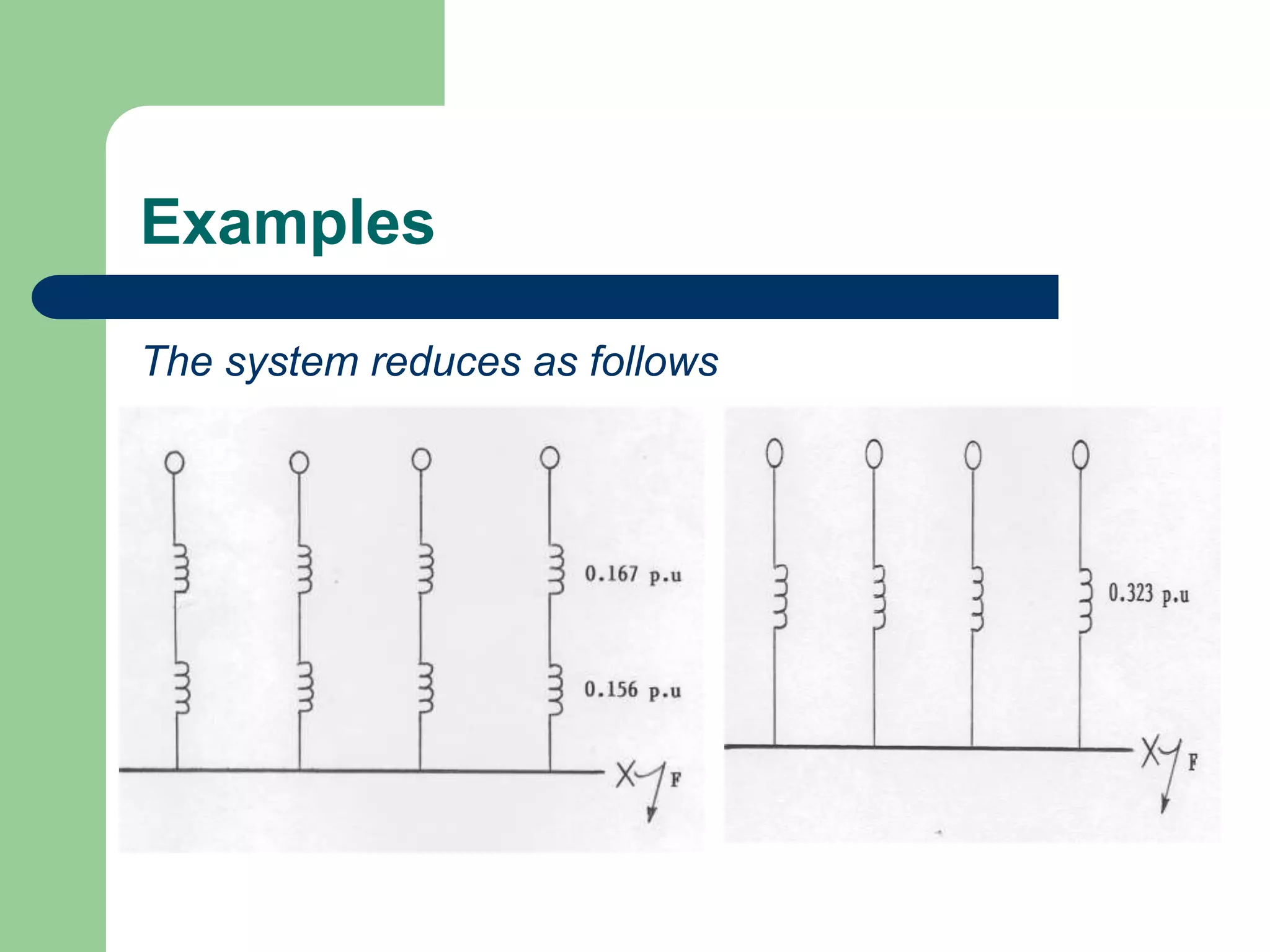
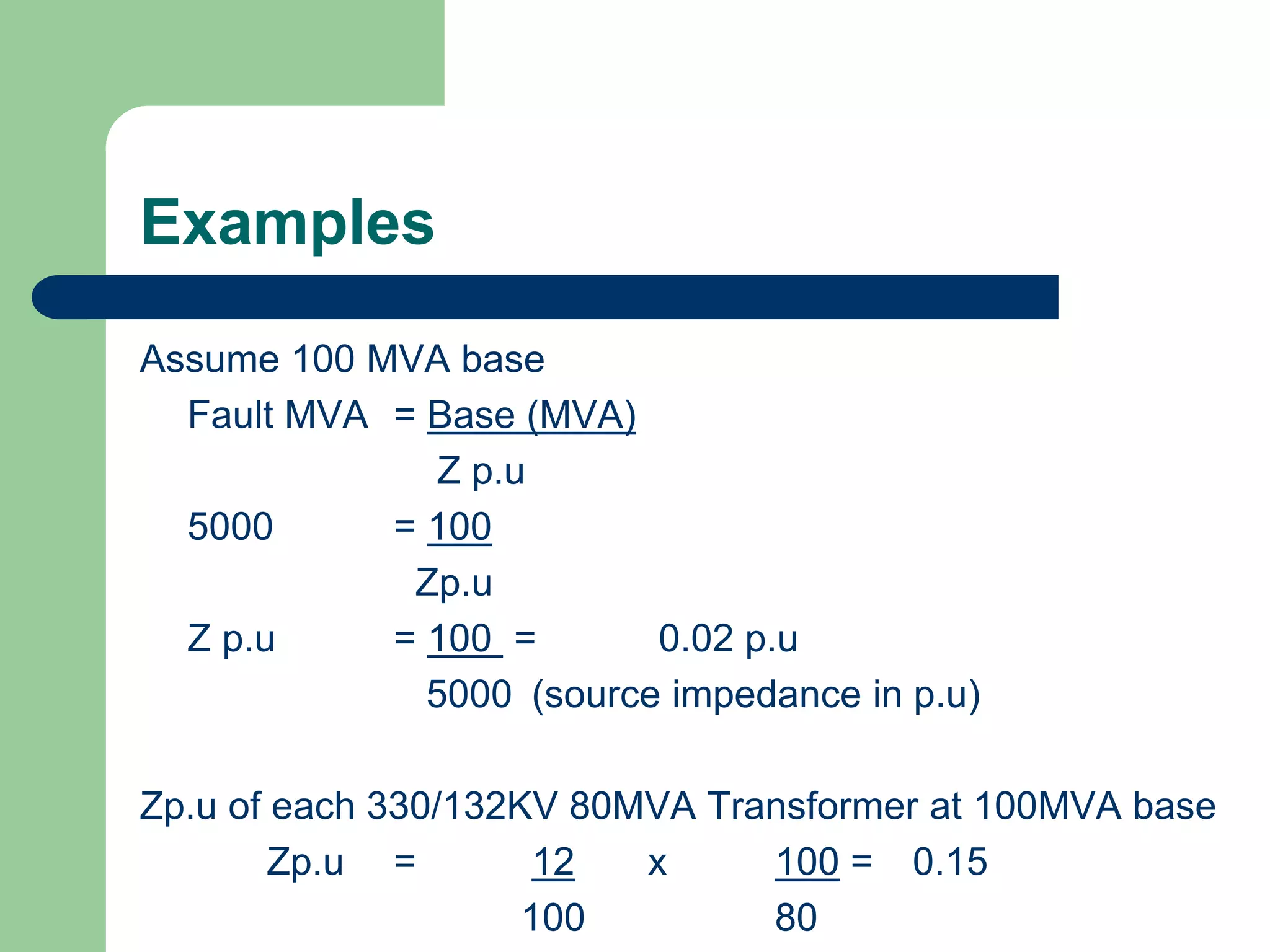
![Examples
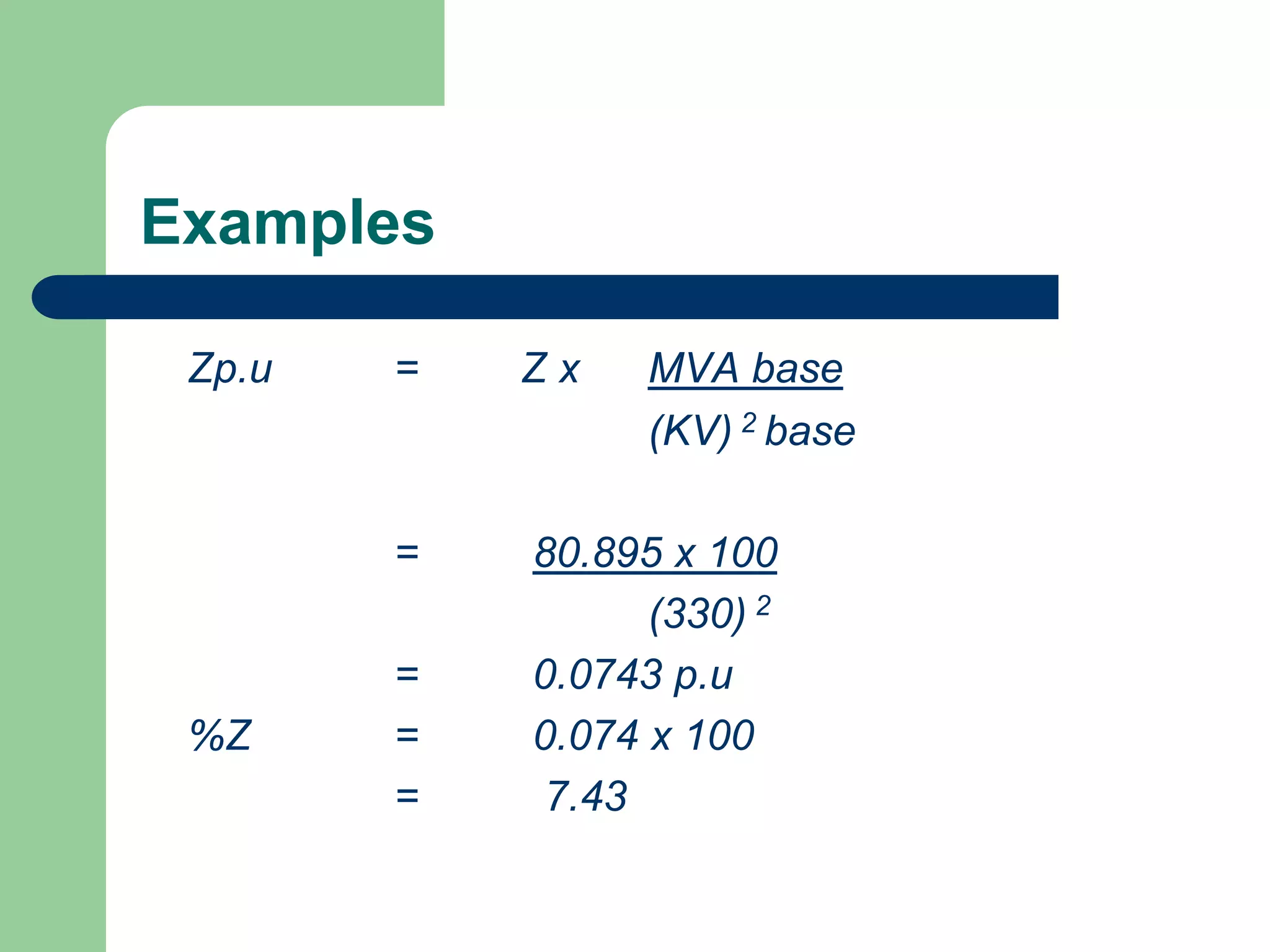
Z = R + jX
For the 200kms line length
Z = 200 (0.06 + j 0.4)
= 12 + j 80
|Z| = [(12) 2 + (80) 2] = 80.895 ohms](https://image.slidesharecdn.com/283481961-power-system-faults-ppt-220924070421-12317c7c/75/283481961-POWER-SYSTEM-FAULTS-ppt-ppt-43-2048.jpg)

![Examples
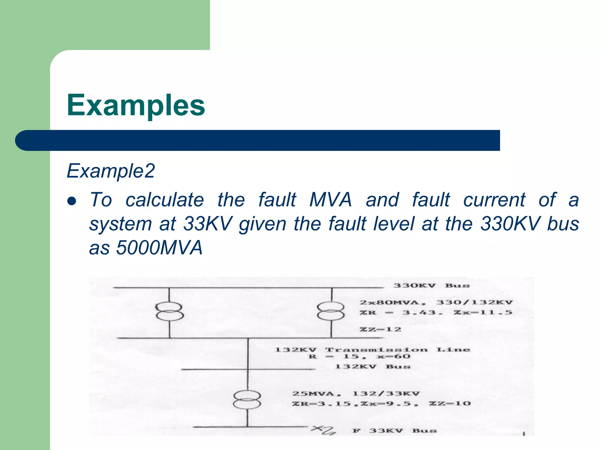
Z1 of 132KV Trans. line = 15 + j 60 = R + jX
= [(15) 2 + (60) 2 ]
= 61.85 0hms
Z1 p.u. of this line = (Z) MVA base
(KV) 2
= (61.85) x 100
(132) 2
= 0.355 p.u](https://image.slidesharecdn.com/283481961-power-system-faults-ppt-220924070421-12317c7c/75/283481961-POWER-SYSTEM-FAULTS-ppt-ppt-53-2048.jpg)