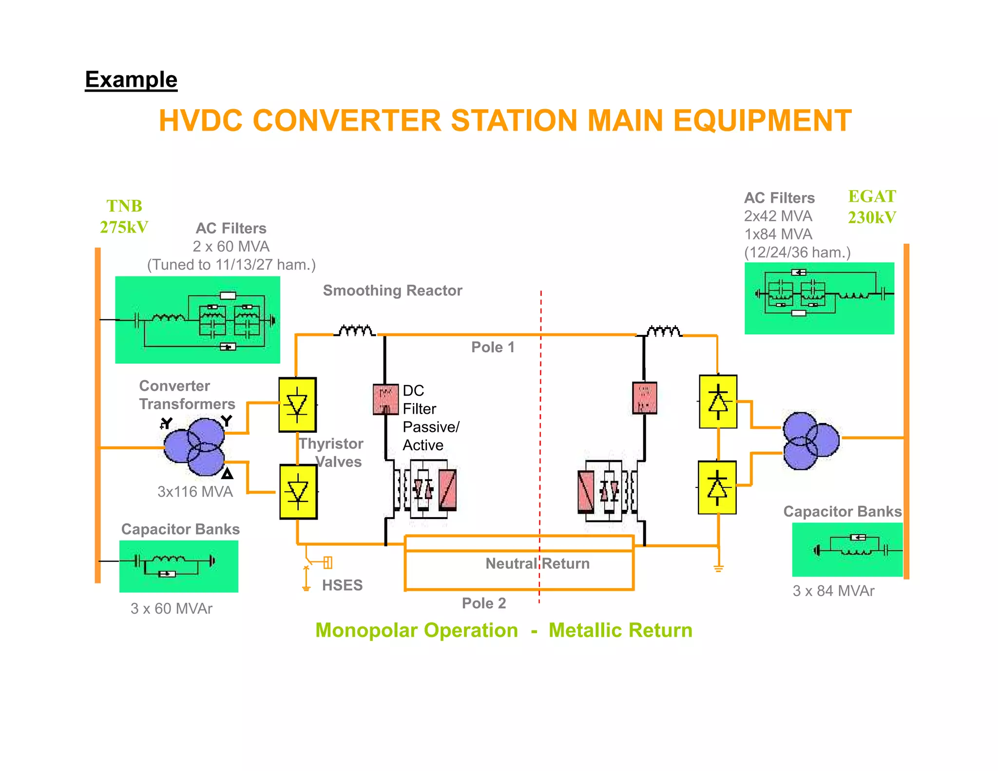
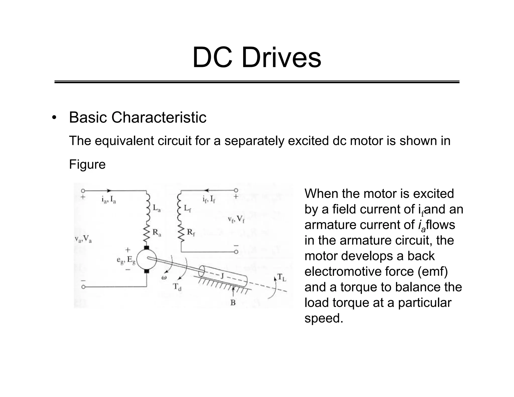
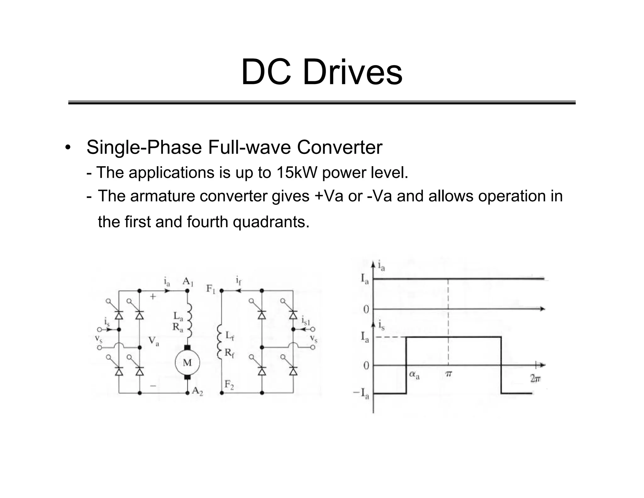
This document discusses power electronics applications in DC and AC drives. It describes the basic characteristics and equivalent circuits of DC motors and how their speed can be controlled through various single-phase and three-phase converter configurations. It also summarizes the operation of induction motors, including cage and slip-ring types, and how their speed can be controlled through variable frequency inverters or by adjusting the slip-ring voltage. The document concludes by outlining the main components of HVDC converter stations used for long distance and asynchronous power transmission.

![AC Drives
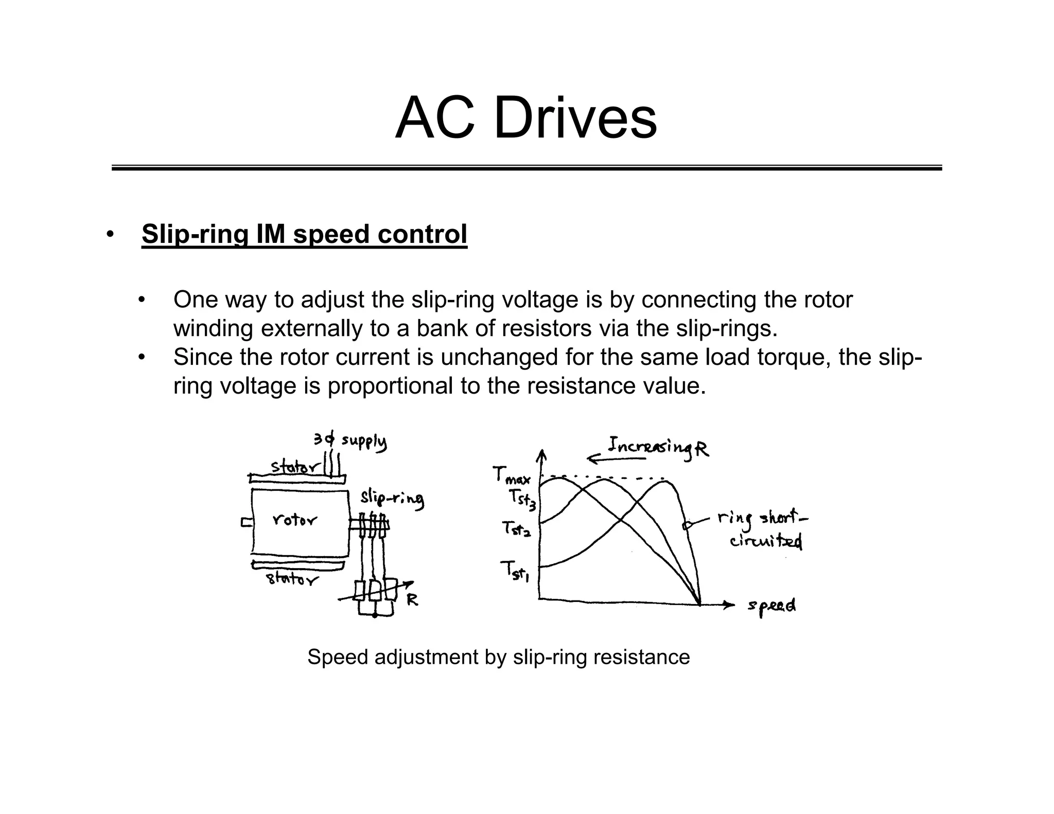
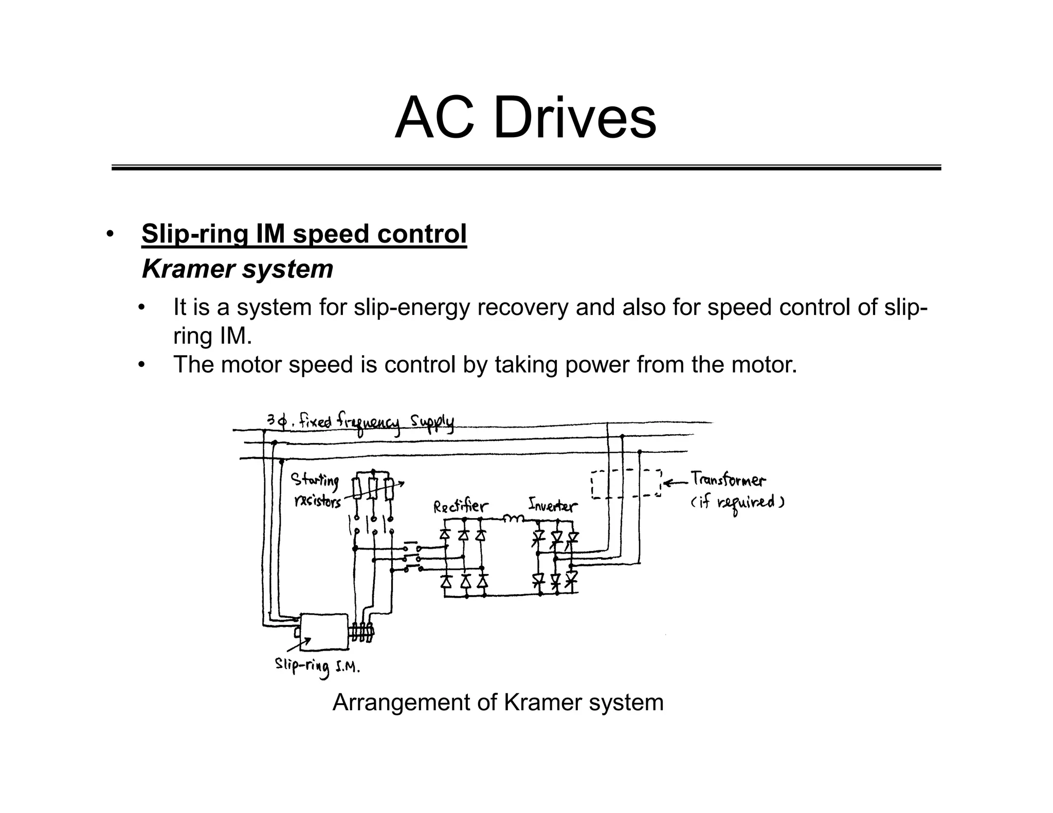
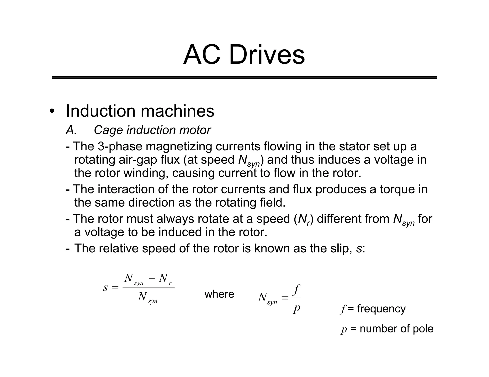
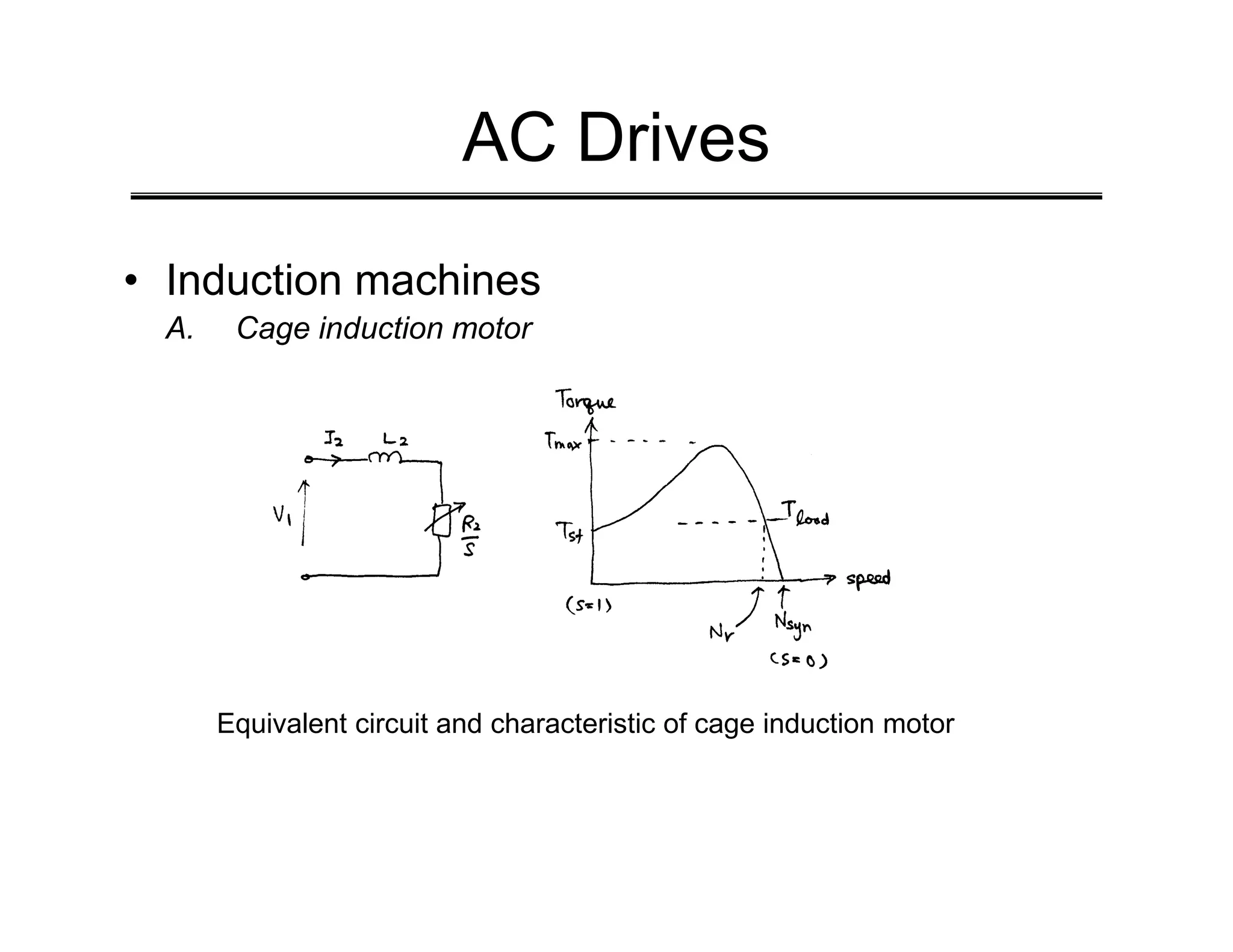
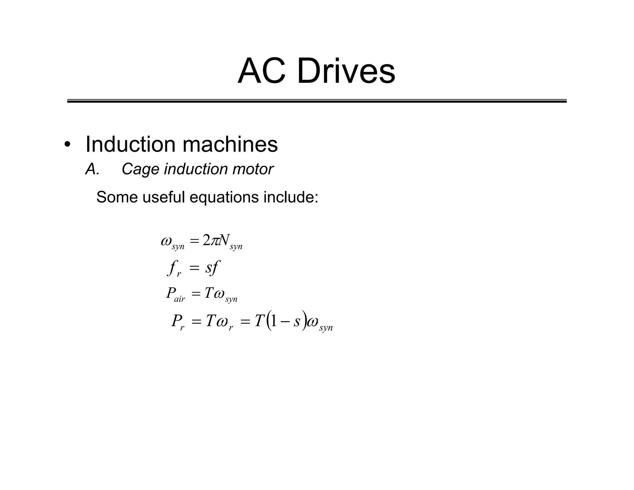
• Induction machines
A. Cage induction motor
If the stator winding resistance and leakage reactance (R) are
ignored, the flux may be considered constant at all loads and
proportional to the applied stator voltage.
( )
[ ]
2
2
2
2
2
2
1
2 R
sfL
R
sV
T
syn +
=
π
ω](https://image.slidesharecdn.com/chapter7-230622144312-a89071f3/75/Chapter-7-Application-of-Electronic-Converters-pdf-13-2048.jpg)