This document provides an introduction to computer networking. It discusses the client-server model and different types of networks, including local area networks (LANs), metropolitan area networks (MANs), wide area networks (WANs), wireless networks, and internetworks. LANs connect computers within a small physical area like a building and operate at speeds of 10 to 100 Mbps. WANs span large distances like countries and connect multiple LANs. Internetworks are formed when distinct networks are connected through routers and hosts to allow communication between incompatible networks. The chapter aims to explain the basic concepts of computer networks and networking.


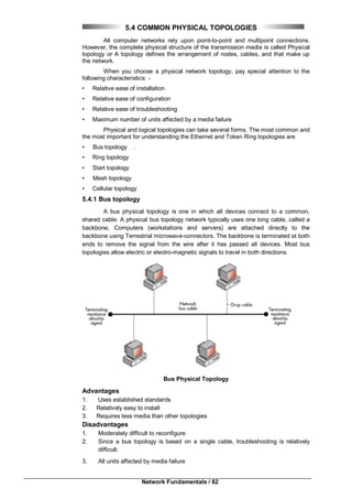


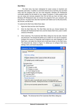
![Windows XP / 115
Chapter 10
Windows XP
10.0 Objectives
10.1 Introduction
10.2 Multitasking
10.3 Windows XP Structure
10.4 Sharing Folders and Printers
10.5 To Share a folder with Share Level
Access Control
10.6 Summary
10.7 Check your Progress - Answers
10.8 Questions for Self – Study
10.9 Suggested Readings
10.0 OBJECTIVES
After studying this chapter you will be able to-
Explain basic concept of operating system of Multitasking.
Explain Windows XP.
10.1 INTRODUCTION
An Operating system is a part of system software that is loaded in to computer
on boot up that is responsible for running other applications and provides interface to
interact with other programs that uses system hardware.
This interface is either command line user interface or Graphical User
Interface. Command Line User interface is used in operating systems like MSDOS,
UNIX, LINUX etc. and GUI is used with most of MS Windows operating systems like
Windows XP , Windows Vista Windows 7 etc.
Operating system can be divided into two groups : 1] Single process & 2] Multi
process.
Single process operating systems are capable of working on one task at a
time while multi process operating systems can work on several processes at once by
breaking the tasks into threads. Smallest part of programs that can be scheduled for
execution is called as a thread. There are several terms related to multiprocessing
which are as follows
10.2 MULTITASKING
It is the capability of an operating system to handle more than one task at a
time. There are two types of multitasking
1] Co-operative Multitasking 2] Preemptive multitasking.
1. Co-operative Multitasking
Applications can control the system resource until they are finished. If a task](https://image.slidesharecdn.com/bca-221networkfundamentals-161110195023/85/Bca-221-network-fundamentals-115-320.jpg)
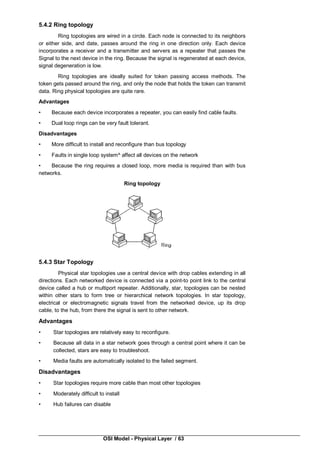
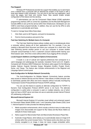
![Network Fundamentals / 116
caused faults or other problems, it would cause the system to become unstable
and force a reboot. This type of multitasking is used in Windows 3.x.
2. Preemptive Multitasking
Applications are allowed to run for a specified period of time depending on how
important the application is to the operation of the system (priority basis). If a
particular task is causing problems or faults, that application can be stopped
without the system becoming unstable. Used in Windows 9.x, Windows XP,
Vista and Windows 7 and all network operating systems.
Multi user - This is similar to multitasking and is the ability for multiple users to
access resources at the same time. The OS switches back and forth between users.
For example all network operating systems like Windows server 2003, Windows server
2008, Linux, Unix etc.
Multiprocessor - Having multiple processors installed in a system such that
tasks are divided between them. Now all latest operating systems uses symmetric
multiprocessing.
Multiprogramming : It is the capability of an operating system to run multiple
programs at once. Multiprogramming is possible because of multi threading.
Multithreading :- It is the capability of an operating system to handle
(execute) multiple threads of multiple programs at a time. One program may have at
least one thread. Thread is a smallest part of a program that can be scheduled for
execution.
There are two broad categories of operating systems 1] Desktop operating
system 2] Network operating system.
Desktop operating System:-
Features of Desktop operating system
1] It a single user operating system.
2] It can support Multitasking, Multiprogramming, Multiprocessing and
Multithreading. 3] User interface can be command line or GUI.
4] Desktop PCs, workstations and laptops are used to installed desktop operating
systems.
5] Cost of the operating system is low as compare to Network operating system.
6] Desktop operating system can be configured as a client in network environment.
7] Provides user level and share level security.
8] Desktop operating systems are as follows :
MSDOS, Windows 95/98, Windows 2000 Professional, Windows XP, Windows
Vista and Windows 7.
10.3 WINDOWS XP STRUCTURE
Windows XP operating system is either 32 bit or 64 bit operating system that
run in 2 different modes which are kernel(protected) and user. Applications use
Application Program Interfaces(APIs) to pass threads between the 2 modes. User
mode provides no direct access to the system’s hardware.
Windows XP has various editions like Windows XP Home, Windows XP
Professional, Windows XP Media Centre etc. Windows XP supports two way SMP i.e.
it supports maximum two CPUs. Windows XP Home Edition does not take part in
Domain Environment.
Features of Windows XP :-
Windows XP combines the features of Windows 2000 Professional, Windows
98 and Windows ME. The main benefit of using XP include its reliability, performance,
security, ease of use, support for remote users, networking and communication
support, management and deployment capabilities, and help and support features.
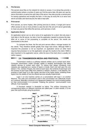
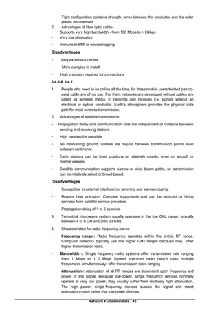
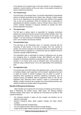
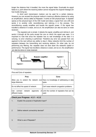
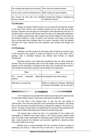
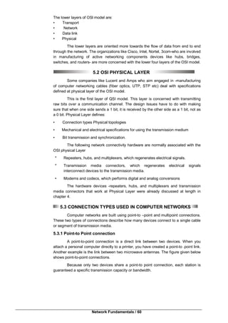
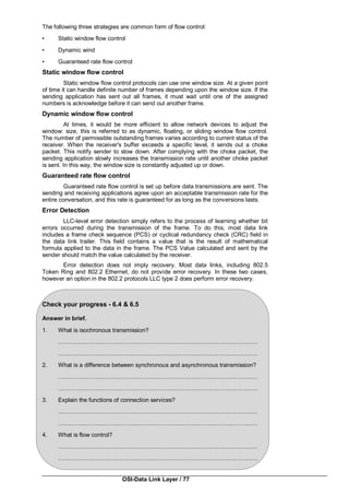
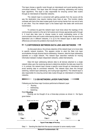
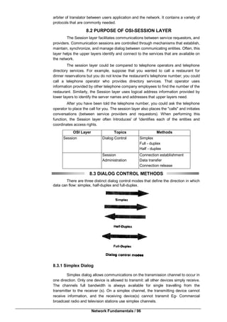
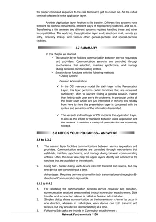
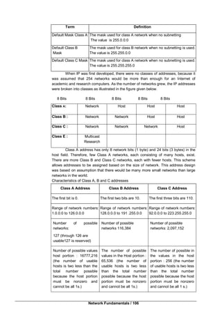
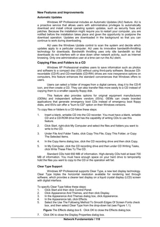
Hardware Requirements
To install Windows XP Professional successfully, your system must meet
certain hardware requirements. Table 1.1 lists the minimum requirements for a x86-
based computer, as well as the more realistic recommended requirements.
The standard Windows XP Professional operating system is based on the Intel
x86-based processor architecture, which uses a 32-bit operating system.](https://image.slidesharecdn.com/bca-221networkfundamentals-161110195023/85/Bca-221-network-fundamentals-116-320.jpg)
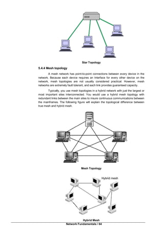
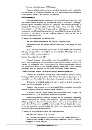
![Windows XP / 117
Windows XP 64-bit edition is the first 64-bit client operating system to be
released by Microsoft. The 64-bit version of Windows XP requires a computer with an
Itanium processor, and is designed to take advantage of performance offered by the
64-bit processor. The hardware requirements for Windows XP 64-bit edition are
different from the hardware requirements of a standard version of Windows XP
Professional. Maximum memory supported by Windows XP is 3GB for 32 bit edition.
Note: Windows XP Professional offers support for a maximum of 2 processors
and a maximum of 4 GB Ram for 64 bit edition.
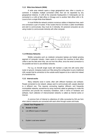
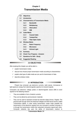
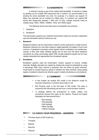
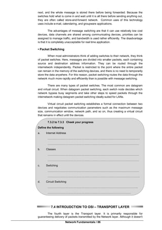
Component Minimum Requirement
Processor Intel Pentium (or compatible)
233MHz or higher
Intel Pentium II (or compatible)
300MHz or higher
Memory 64MB or 128MB
Video adapter and monitor with
SVGA resolution or higher
Peripheral devices like Keyboard, mouse, or other pointing device
Removable storage
CD-ROM or DVD-ROM drive if installing from CD
12x or faster CD-ROM or DVD-ROM
File Systems Supported
Windows XP Professional supports three file systems:
_ File Allocation Table (FAT16)
_ FAT32
_ New Technology File System (NTFS)
While Windows XP Home Edition adds a great deal to the feature set of
Windows 2000, Windows XP Professional takes the product to the next level. Many of
the neat things that are part of Windows 2000 Professional are excluded from the
Home Edition, but they are included in WinXP Professional. These features include the
following:
IntelliMirror technologies
Group Policy functionality
Encrypting file system support
Multiprocessor support
Check your progress
Fill in the blanks
1] Windows XP operating system is either ……………… bit or ……………… bit
operating system.
2] Windows XP operating system that run in 2 different modes which are
……………… and ………………
3] Windows XP supports maximum ……………… CPUs.
4] Maximum memory supported by Windows XP is ………………
5] Windows XP ……………… edition does not take part in Domain environment.](https://image.slidesharecdn.com/bca-221networkfundamentals-161110195023/85/Bca-221-network-fundamentals-117-320.jpg)
![Network Fundamentals / 126
text box, and then click OK. This opens a command prompt, which you use to request
the Convert command. The following example shows how you might use switches with
the Convert command.
Convert volume /FS:NTFS [/V] [/CvtArea:filename] [/Nosecurity] [/X]
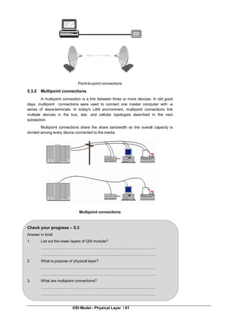
Table 2.2 lists the switches available in the Convert command and describes
their functions.
Table 2.2 Convert Command Switches
Switch Function Required
Volume Specifies the drive letter (followed by a colon), volume
mount point, or volume name that you want to convert
Yes
/FS:NTFS Specifies converting the volume to NTFS Yes
/V Runs the Convert command in verbose mode No
/CvtArea:filename Specifies a contiguous file in the root directory to be
the placeholder for NTFS system files
No
/NoSecurity Sets the security settings to make converted files and
directories accessible by everyone
No
/X Forces the volume to dismount first if necessary, and
all open handles to the volume are then not valid
No
For help with any command-line program, at the command prompt type the
command followed by /? and then press Enter. For example, to receive help on the
Convert command, type Convert /? and then press Enter.
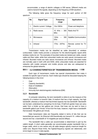
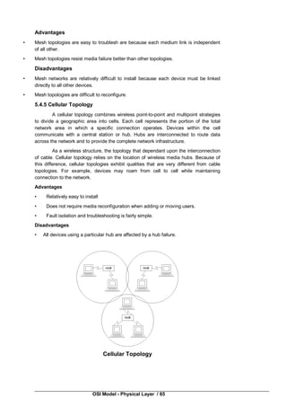
Domain
Figure A Windows 2000 domain
In a domain, the directory resides on computers that are configured as domain
controllers. A domain controller is a server that manages all security-related aspects of](https://image.slidesharecdn.com/bca-221networkfundamentals-161110195023/85/Bca-221-network-fundamentals-126-320.jpg)
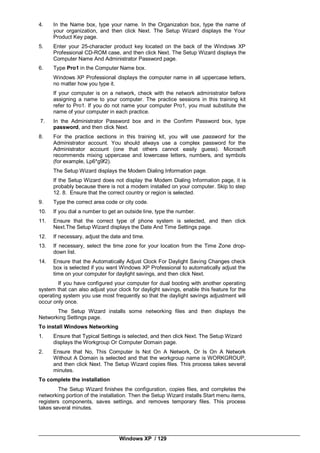
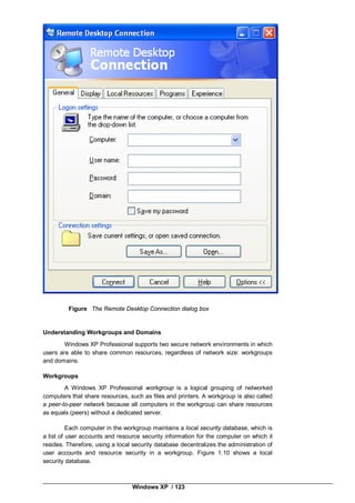
![Windows XP / 131
Note: The string systemroot (typed as %systemroot%) represents the folder in
the boot partition that contains the Windows XP Professional system files.
Preboot Sequence
During startup, a Windows XP Professional-based computer initializes the
boot portion of the hard disk and the preboot sequence begins. This sequence
consists of following steps:
1] The computer runs power-on self test (POST) process to determine the amount
of physical memory and the hardware components are present.
2] If the computer has a Plug and Play (BIOS), enumeration and configuration of
hardware devices occurs.
3] The computer BIOS locates the boot device and loads and runs the master boot
record (MBR).
Note: Windows XP Professional modifies the boot sector during installation so
that Ntldr loads during system startup. Therefore you should disable the Boot Sector
Virus Protection in your BIOS Setup.
Boot Sequence
After the computer loads Ntldr into memory, the boot sequence gathers
information about hardware and drivers in preparation for the Windows XP
Professional load phases. The boot sequence uses the following files: Ntldr, Boot.ini,
Bootsect.dos (optional), Ntdetect.com, and Ntoskrnl.exe.
The boot sequence also has five phases:
• Initial Boot Loader Phase : During the initial boot loader phase, Ntldr switches
the microprocessor from real mode to 32-bit flat memory mode, which Ntldr
requires. Then, Ntldr starts the appropriate the minifile system drivers. The
minifile system drivers are built into Ntldr so that Ntldr can find and load
Windows XP Professional from partitions formatted with either the FAT or NTFS
file system.
• Operating System Selection Phase: During the boot sequence, Ntldr reads the
Boot.ini file. If multiple operating systems are supported on the computer in the
Boot.ini file, then the Please Select The Operating System To Start screen,
which you can use to select the operating system that should be loaded within a
specified time before the default operating system. If no Boot.ini file is present,
Ntldr attempts to load Windows XP Professional from the Winnt folder on the first
partition of the first disk, typically C:Windows
Hardware Detection Phase: On Intel-based computers, Ntdetect.com and
Ntoskrnl.exe perform hardware detection. Ntdetect.com executes if Windows XP
Professional should be loads. Ntdetect.com collects a list of installed hardware
components and returns this list to Ntldr for later inclusion in the registry under the
HKEY_LOCAL_MACHINEHARDWARE key.
• Configuration Selection Phase: After Ntldr starts loading Windows XP
Professional and collects hardware information, the operating system loader
process displays the Hardware Profile/Configuration Recovery Menu screen,
which contains a list of the hardware profiles that have been created on the
computer, if more that one hard profile exists on the computer. The first
hardware profile is highlighted. You can press the Down arrow key to select
another profile. You can also press L to invoke the Last Known Good
Configuration option.
• Windows XP Professional Logon Phase: The Windows XP Professional boot
sequence is complete once the user has successfully logged on at the computer.
Kernel Load
After the configuration selection, Ntoskrnl.exe, the Windows XP kernel loads
and initializes. Ntoskrnl.exe also loads and initializes device drivers and loads
services. If you press Enter when the Hardware Profile/Configuration Recovery Menu
screen displays, or if Ntldr makes the selection automatically, the computer enters the
kernel load phase. The screen clears and a series of white rectangles appears across
the bottom of the screen. During the kernel load phase, Ntldr:](https://image.slidesharecdn.com/bca-221networkfundamentals-161110195023/85/Bca-221-network-fundamentals-131-320.jpg)
![Network Fundamentals / 132
• Loads Ntoskrnl.exe but does not initialize it.
• Loads the hardware abstraction layer file (Hal.dll).
• Loads the HKEY_LOCAL_MACHINESYSTEM registry key.
• Selects the control set required to initialize the computer.
• Loads device drivers with a value of 0x0 for the Start entry. These are typically
low-level hardware device drivers, such as those for a hard disk.
When the kernel load phase is complete, the kernel initializes and takes
control from Ntldr. The system displays a graphical screen with a status bar that
indicates load status. During the kernel initialization stage four tasks are performed:
• The Hardware key is created.
• The Clone control set is created.
• Device drivers are loaded and initialized.
• Services are started.
Logon
The logon process begins at the end of the kernel initialization phase, when
the Win32 subsystem automatically starts Winlogon.exe, which starts Local Security
Authority (Lsass.exe) and displays the Logon dialog box. This allows you to log on
while Windows XP initializes the network device drivers.
Note: Windows XP startup is not considered successful until a user logs on at
the computer. After a logon, the system automatically copies the Clone control set to
the Last Known Good control set making the current control set the Last Known Good
Configuration.
Check Your Progress 10.2
State True or False
1] Windows XP is a Network operating system.
2] Windows XP Professional can take part in Domain Networks.
3] NTFS 5 file system supports user quota and disk quota.
4] You can convert FAT or FAT32 file system to NTFS file system without
Match the followings
1] Windows XP operating system 1] Peer to Peer Network
2] FAT32 file system 2] Desktop Operating System
3] Workgroup 3] No File Level security
4] NTFS 4] c:windows
5] System root 5] Disk Compression
10.4 SHARING FOLDERS AND PRINTERS
If you set up a Microsoft or Novell network client, you can share your
documents-and any printers attached to your computer-with other people on the
network. To use file and print sharing, you must first choose which of two types of
access you want to give other users.
• Share level control is default access setting. It lets you require a password for
each shared resource.
• User-level control lets you specify who has access to each shared resource, but
it doesn't let you require a password.](https://image.slidesharecdn.com/bca-221networkfundamentals-161110195023/85/Bca-221-network-fundamentals-132-320.jpg)
![Network Fundamentals / 134
3. On the sharing tab, click shared as.
4. In share name, type a name for printer. In comment you can type brief
component description of the printer
5. Clicks add.
6. In the add users dialog box, click the names of the people to whom you want to
grant permissions.
7. Click full access.
10.6 SUMMARY
An operating system is a part of system software that is loaded into computer
on boot up that is responsible for running other applications and provide interfaces to
interact with other programs that uses system hardware.
Multitasking is the capability of operating system to handle more than one task
of a time.
Two types of Multitasking.
i) Co-operative Multitasking
ii) Preemptive Multitasking.
Windows XP operating system is either 32 bit or 64 bit operating system that
run in two different modes which are kernel & user, Windows XP supports three file
systems.
i) File Allocation table (Fat16)
ii) FAT 32
iii) New Technology file system (NTFS)
Microsoft designed the internet connection firewall (ICF) for use in the home
and by small businesses. It provides protection on computers directly connected to
internet, A Windows XP professional supports two secure network environments in
which users are able to share common resources, regardless of network size
Workgroup and domains.
A domain is a logical grouping of network computers that share a central
directory database.
Source : http://etutorials.org
10.7 CHECK YOUR PROGRESS – ANSWERS
10.1
Fill in the blanks
1] 32 bit or 64 bit
2] Kernel and User
3] 2 CPUs.
4] 4GB
5] Home
10.2
1] False
2] True
3] True
4] True
5] False
Match the followings
1] – 2]
2] –3]
3] –1]
4] --5]
5] –4] .](https://image.slidesharecdn.com/bca-221networkfundamentals-161110195023/85/Bca-221-network-fundamentals-134-320.jpg)

![Network Fundamentals / 138
range of the client, the firmware may decide based on signal strength to which of two
APs it will connect.
Wi-Fi uses spectrum near 2.4 GHz, which is a standardized and unlicensed by
international agreement.
11.3 EXAMPLES OF WI-FI DEVICES
Wireless Access Point (WAP)
A wireless access point connects a group of wireless stations to adjacent
wired local area network (LAN). An access point is similar to an Ethernet Hub, but
instead of relaying on LAN data only to other LAN stations, an access point can relay
wireless data to all other compatible wireless devices as well as LAN stations
connected by wires.
Wireless Routers
A wireless router connects a group of Wi-Fi enabled devices (i.e. PDAs,
laptops etc) to adjacent wired network (such as cable modem or DSL modem). A
wireless access router is a wireless access point combined with an Ethernet Hub. A
wireless router forwards between your wireless subnet and any other subnet.
Wireless Ethernet Bridge
A wireless Ethernet Bridge connect two separate networks.
Wi-Fi supported operating systems:-
1] Microsoft Windows XP, Vista and Windows 7 have a good support for wireless.
2] Mac Operating system has good Wi-Fi support and operating system includes
native support for Apple “AirPort” Wi-Fi cards.
3] Linux has excellent support for most of wireless cards.
11.1 Check Your Progress
Fill in the blanks
A] Wi-Fi stands for ………………..
B] Wi-Fi users ………………..as its carrier.
C] A ………………..connects a group of wireless stations to adjacent wired local
area network (LAN).
D] A ………………..connect two separate networks.
Wireless Capabilities :-
1] It provides temporary connections to and existing cable (Wired) networks.
2] Provides backup (redundant) to an existing wired networks.
3] Extend the networks beyond the limits of copper or even fiber optic cables.
Usage of Wireless Networks:-
1] Busy areas such as lobbies, and reception areas.
2] For people who are constantly on move such as doctors in hospitals, in isolated
areas.
3] Buildings or departments where physical settings changes frequently.
3] Structures such as historical buildings where cabling would be difficult.](https://image.slidesharecdn.com/bca-221networkfundamentals-161110195023/85/Bca-221-network-fundamentals-138-320.jpg)
![Wireless Networks / 141
is encumbered with legacy issues that reduce throughput when compared to 802.11a
by ~21%.
The then-proposed 802.11g standard was rapidly adopted by consumers
starting in January 2003, well before ratification, due to the desire for higher data rates
as well as to reductions in manufacturing costs. By summer 2003, most dual-band
802.11a/b products became dual-band/tri-mode, supporting a and b/g in a single
mobile adapter card or access point. Details of making b and g work well together
occupied much of the lingering technical process; in an 802.11g network, however,
activity of an 802.11b participant will reduce the data rate of the overall 802.11g
network.
Like 802.11b, 802.11g devices suffer interference from other products
operating in the 2.4 GHz band.
In 2003, task group TG ma was authorized to "roll up" many of the
amendments to the 1999 version of the 802.11 standard. REV ma or 802.11ma, as it
was called, created a single document that merged 8 amendments
(802.11a,b,d,e,g,h,i,j) with the base standard. Upon approval on March 8, 2007,
802.11REVma was renamed to the current base standard IEEE 802.11-2007.
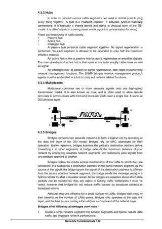
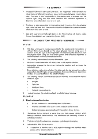
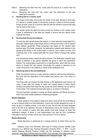
802.11n
802.11n is a recent amendment which improves upon the previous 802.11
standards by adding multiple –input multiple –output (MIMO) and many other newer
features. The IEEE has approved the amendment and it was published in October
2009. Prior to the final ratification, enterprises were already migrating to 802.11n
networks based on the Wi-Fi Alliance’s certification of products conforming to a 2007
draft of the 802.11n proposal.
Release
date
Op.
Frequency
Throughput
(typ.)
Net Bit Rate
(max.)
Gross
Bit Rate
(max.)
Max
Indoor
Range
Max
Outdoor
Range
September
11, 2009
5 GHz
and/or
2.4 GHz
50–
144 Mbit/s
600 Mbit/s
450
Mbit/s
~229
feet/70
meters
~820
feet/250
meters
Modes of Operations
Peer to Peer or Ad-Hoc Mode
This is a method for wireless devices to directly communicate with each other.
Operating in ad-hoc mode allows wireless devices within range of each other to
discover and communicate in peer to peer fashion without involving central access
points.
This is typically used by two PCs to connect to one another so that one can
share the other’s internet connection for example as well as for wireless mesh
networks.
Infrastructure Mode (Access point /Client)
The most common is to have access points wired to Internet, and having
wireless clients (typically Laptops) accessing Internet through the access point. This is
also called as Infrastructure Mode.
11.5 ADVANTAGES AND DISADVANTAGES OF
WIRELESS NETWORKS
Advantages of Wireless Networks
1] Allows LANs to be deployed without cabling, potentially reducing costs of
network deployment and expansion. Spaces where cables cannot be run, such
as outdoor areas and historical buildings, can host wireless networks.](https://image.slidesharecdn.com/bca-221networkfundamentals-161110195023/85/Bca-221-network-fundamentals-141-320.jpg)
![Network Fundamentals / 142
2] Wi-Fi silicon pricing continues to come down, making Wi-Fi a very economical
networking option.
3] Wi-Fi products are widely available in the market. Different brands of access
points and client network interfaces are interoperable at the basic level of
service.
4] Wi-Fi networks support roaming, in which a mobile client station such as a laptop
can move from one access point to another as the user moves around in the
building areas.
Disadvantages of Wireless Networks
1] Power consumption is fairly high, making battery life and heat a concern.
3] The most common wireless encryption standard, Wired Equivalent Privacy or
WEP has been shown to be breakable even when correctly configured.
3] Wi-Fi networks have limited range. A typical Wi-Fi home router using 802.11b or
802.11g standard with a stock antenna might have a range of 45 Meters (Indoor)
and 90 Meters (outdoor).
4] Wi-Fi networks can be monitored and used to read and copy data (including
personal information) transmitted over the network when encryption is not
enabled.
5] The frequency which 802.11b and 802.11g operates is 2.4GHz which can lead
to interference with cordless phones in the super high frequency range.
11.2 Check your progress
Fill In the blanks
1] ……………... is IEEE standard for Wireless Networks.
2] 802.11a wireless standard supports data transfer speed up to ……………...
3] 802.11b wireless standard supports data transfer speed up to ……………...
4] 802.11g wireless standard supports data transfer speed up to ……………...
5] 802.11n wireless standard supports data transfer speed up to ……………...
6] There are two modes of operation for wireless networks ……………... and
……………...
7] WEP stands for ……………...……………...
8] WPA stands for ……………...……………...
State True or false
1] Wireless networks are secured networks……………...
2] Wireless Access points are required in Infrastructure Mode. …………
3] Power consumption of wireless devices is very less. ……………...
4] Wi-Fi networks has unlimited network range. ……………...
5] Wireless networks are easy to configure. ……………...
11.6 WIRELESS SECURITY
WEP (Wired Equivalent Privacy)
Short for Wired Equivalent Privacy, a security protocol for wireless local area
networks (WLANs) defined in the 802.11b standard. WEP is designed to provide the
same level of security as that of a wired LAN. LANs are inherently more secure than
WLANs because LANs are somewhat protected by the physical of their structure,](https://image.slidesharecdn.com/bca-221networkfundamentals-161110195023/85/Bca-221-network-fundamentals-142-320.jpg)
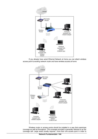
![Wireless Networks / 145
have adequate coverage. You can also add access point to existing wireless router to
improve the coverage.
Wireless Operating Mode
The IEEE 802.11 standards is used to connect computers with wireless
network adapters, also known as wireless clients, to an existing wired network with the
help from wireless router or access point. The two examples specified above operates
in this mode. This is known as infrastructure mode.
Ad hoc mode is used to connect wireless clients directly together (Peers)
without the need for wireless router or access point. An ad hoc network consists of up
to 9 wireless clients, which send their data directly to each other.
11.8 SUMMARY
Wi-Fi underlying technology of wireless Local Area Network (WLAN) based on
LEEE 802.11 specification. The typical Wi-Fi set up contains one or more Access
Points (AP) and one or more clients. Wi-Fi uses spectrum near 2.4 GHz which is a
standardized and unlicensed by international agreement. Examples of Wi-Fi devices
are WAP, Wireless Routers. Wireless Ethernet Bridge.
IEEE 802.11 is a set of Wireless standard carrying out WLAN communication.
There are two types of Mode of operations
i)Peer to peer or Ad-Hoc Mode.
ii) Infrastructure Mode
Wifi silicon pricing continues to come down, making Wi-Fi a very economical
networking option. The disadvantage of wireless Network is about power consumption.
The power consumption is very high, making battery life and heat a concern.
Wired Equivalent Privacy (WEP) is a security protocol for WLAN. WEP is
designed to provide the same level of security as that of wired LAN LAN’s are
inherently more secure than WLAN.
Source : http://centralupload.com(Link)
11.9 CHECK YOUR PROGRESS – ANSWERS
11.1
Fill in the blanks
A] Wireless Fidelity. B] Radio waves.
C] Wireless Access Point D] Wireless Bridge
11.2
1] 802.11 2] 54Mbps 3] 11Mbps 4] 54Mbps
5] 600Mbps
6] Peer to Peer Mode and Infrastructure Mode
7] Wired Equivalent Privacy 8] WPA
State True or false
1] False 2] True 3] False 4] False 5] True
11.10 QUESTIONS FOR SELF–STUDY
1) Write a short Note on Wireless Network
2) What are the examples of Wi-Fi devices?
3) What are the Wireless standards?
4) What are the advantages & disadvantages of Wireless Network?
5) Write a short Note on wireless Security.
11.11 SUGGESTED READINGS
1. Computer Networks : Andrew Tanenbaum
2. Computer Networks : A Top Down Approach by Behrouz forouzan mosharraf
3. Networking Essentials : Emmett Dulaney
](https://image.slidesharecdn.com/bca-221networkfundamentals-161110195023/85/Bca-221-network-fundamentals-145-320.jpg)