Basic Processes of Gaseous Electronics Leonard B. Loeb
Basic Processes of Gaseous Electronics Leonard B. Loeb
Basic Processes of Gaseous Electronics Leonard B. Loeb
Basic Processes of Gaseous Electronics Leonard B. Loeb
Basic Processes of Gaseous Electronics Leonard B. Loeb
1.
Read Anytime AnywhereEasy Ebook Downloads at ebookmeta.com
Basic Processes of Gaseous Electronics Leonard B.
Loeb
https://ebookmeta.com/product/basic-processes-of-gaseous-
electronics-leonard-b-loeb/
OR CLICK HERE
DOWLOAD EBOOK
Visit and Get More Ebook Downloads Instantly at https://ebookmeta.com
2.
Recommended digital products(PDF, EPUB, MOBI) that
you can download immediately if you are interested.
Electrical Coronas Leonard B. Loeb
https://ebookmeta.com/product/electrical-coronas-leonard-b-loeb/
ebookmeta.com
Grob's Basic Electronics, 13th Edition Mitchel Schultz
https://ebookmeta.com/product/grobs-basic-electronics-13th-edition-
mitchel-schultz/
ebookmeta.com
Basic Electronics Theory and Practice 3rd Edition Sean
Westcott
https://ebookmeta.com/product/basic-electronics-theory-and-
practice-3rd-edition-sean-westcott/
ebookmeta.com
Magic in Manhattan Collection Magic in Manhattan 1 3 1st
Edition Allie Therin
https://ebookmeta.com/product/magic-in-manhattan-collection-magic-in-
manhattan-1-3-1st-edition-allie-therin/
ebookmeta.com
3.
Procurement and SupplyChain Management, 8e Arjan J. Van
Weele
https://ebookmeta.com/product/procurement-and-supply-chain-
management-8e-arjan-j-van-weele/
ebookmeta.com
Applied Deep Learning with TensorFlow 2: Learn to
Implement Advanced Deep Learning Techniques with Python
2nd Edition Umberto Michelucci
https://ebookmeta.com/product/applied-deep-learning-with-
tensorflow-2-learn-to-implement-advanced-deep-learning-techniques-
with-python-2nd-edition-umberto-michelucci/
ebookmeta.com
What Really Happens in Vegas True Stories of the People
Who Make Vegas Vegas 1st Edition Patterson
https://ebookmeta.com/product/what-really-happens-in-vegas-true-
stories-of-the-people-who-make-vegas-vegas-1st-edition-patterson/
ebookmeta.com
Fit and Healthy from 1 to 100 with Nutrition and Exercise
Current Medical Knowledge on Health Mathias
https://ebookmeta.com/product/fit-and-healthy-from-1-to-100-with-
nutrition-and-exercise-current-medical-knowledge-on-health-mathias/
ebookmeta.com
Roots of the Bible An ancient view for a new outlook 3rd
Edition Friedrich Weinreb
https://ebookmeta.com/product/roots-of-the-bible-an-ancient-view-for-
a-new-outlook-3rd-edition-friedrich-weinreb/
ebookmeta.com
4.
Constructions of CulturalIdentities in Newsreel Cinema
and Television after 1945 Kornelia Imesch (Editor)
https://ebookmeta.com/product/constructions-of-cultural-identities-in-
newsreel-cinema-and-television-after-1945-kornelia-imesch-editor/
ebookmeta.com
L E ON A R D B . L O E B
BASIC PROCESSES OF
GASEOUS ELECTRONICS
U N I V E R S I T Y O F C A L I F O R N I A P R E S S
B E R K E L E Y A N D L O S A N G E L E S • 1 9 5 5
8.
University of CaliforniaPress
Berkeley and Los Angeles, California
Cambridge University Press
London, England
Copyright, 1955, by
The Regents of the University of California
L. C. Catalog Card No.: 55-5196
Printed in the United States of America
Designed by John B. Coetz
9.
This book ishumbly dedicated to that
group of capable and enthusiastic young
physicists, theoretical and experimental,
with their fine appreciation of modern
atomic physics and kinetic theory, who
have, dwing and since World War II, in
America, England, Germany, and Italy,
rejuvenated the field of study previously
called the Discharge of Electricity
in Gases, and now more properly
called Gaseous Electronics.
11.
PREFACE
The author publisheda book in 1939, entitled Fundamental Proc-
cesses of Electrical Discharge in Gases. Except for the last two
chapters dealing with glow and arc discharges, it presented a compre-
hensive, up-to-date review of the field, based on actual experimental
acquaintance with the various subjects treated. This was the result
of many years' work by the author and his students. Such a critical
review was then urgently needed, since the accumulated and often
conflicting researches and theory of nearly forty years, carried out
with techniques ranging from those of the most primitive type to the
improved techniques and atomic theory of the nineteen-thirties, had
been adopted and used indiscriminately by various workers without
analysis. Several earlier books written on the subject had either been
compilations of past work, or were somewhat specialized monographs,
presenting the methods and theories of some school of workers in a
more restricted sphere.
Two somewhat more timely compilations then existing require
separate mention. One of these was the excellent review of limited
scope by K. T. Compton and I. Langmuir in Reviews of Modem Physics
of 1930-1931. The other was a more unified treatment of the whole
subject, based on sound atomic theory as of 1930, written by A. von
Engel and M. Steenbeck in two volumes that were published in 1931
and 1934. The latter books were basically not critical of the subject
material. The kinetic theory there used was relatively primitive, and
was presented without indicating its weakness. The worst defect of
the books was their lack of proper references and coverage of the
literature. The author's book in 1939 thus filled a particular need.
Fifteen years have passed since Fundamental Processes appeared.
During those years, a major war has accelerated technical advance
to the point where new tools and methods, such as microwave tech-
niques, square pulsed potentials of short duration, improved vacuum
techniques, and high-speed oscilloscopes have permitted developments
that were previously impossible. In the same period have appeared
certain major theoretical and experimental contributions to the subject.
Many of these lie in generalizations of the methods of Chapman and
v i i
12.
Preface
Cowling to theanalysis of electron-energy distributions in gases to
include microwave fields and carriers of all masses at all energies; a
unification of methods and techniques, with consequent much better
agreement in the conclusions drawn.
There has been a mature mathematical physical analysis of the
generalized recombination problem by G. Jaff£, which has clarified
past controversies and placed the subject on a sound basis. There
has also appeared an excellent summary of certain aspects of the
breakdown problems as developed before 1939 in the famous Philips
Research Laboratory at Eindhoven by M. J. Druyvesteyn and F . M.
Penning, published in Reviews of Modern Physics in 1940. The
streamer theory of the mechanism of the electric spark, with all of
its implications, especially in connection with photoionization in
gases, was completed in this period, and newer techniques were
applied to establish its reality and limitations. Again, the fast Geiger
counter anode mechanism and the photoelectrically conditioned burst-
pulse corona were analyzed in detail during this period.
Another significant advance lay in the summary and unification of
the researches of J. S. Townsend, V. A. Bailey, and their school,
published in The Behaviour of Slow Electrons in Gases, by R. H.
Healey and J. W. Reed in 1941. Later researches, notably by L . G. H.
Huxley, introduced improvements in techniques and analysis of the
Townsend measurements, thus bringing them more into line with the
methods of other workers.
Probably most important of all in the current rebirth of this field
of study was the invasion during the war and afterward by a group of
brilliant, modern young physicists, both theoretical and experimental,
who were well trained in the kinetic theory of nonequilibrium gases,
modern atomic theory, and modern laboratory techniques. It should
also be added that in this country during the past several years, the
workers in this field have tightened the bonds of common scientific
interest through an annual convention, entitled the "Conference on
Gaseous Electronics," for the discussion of common problems. This
has resulted in far better co-operation, co-ordination of work, and
avoidance of duplication and polemics, thus further accelerating
progress. Under these happy auspices, the advances made in the last
ten years merit incorporation into the somewhat clarified and organized
body of knowledge which was striven for in the author's Fundamental
Processes. It is his hope that in the present book the first step will
have been made toward achieving this goal.
Obviously, the problem could not have been solved by writing a
new edition of the earlier work. The old book laid many ghosts of the
13.
ix P re f a c e
past which require no comment today. Furthermore, the new material
is so extensive that it must be approached de novo in many instances.
In order to be of value, the present work must serve not only for use
in instruction in the subject, but, even more, for the benefit of the
engineer or physicist who is not conversant with the field of gaseous
electronics, there must be a simplified phenomenological or kinetic-
theoretical introduction to each topic, as there was in the earlier
book. Then, on the basis of experimental findings and later theo-
retical development, there will be presented the more esoteric ad-
vances. Obviously, it is impossible to include in detail the elaborate
mathematical physical analyses, but enough of the analytical approach
can be given to indicate the physics underlying the main trend of the
study, together with its logical conclusions.
Considerable emphasis is placed on laying the proper, simplified
physical foundation, in order that the later more complicated and subtle
implications of seemingly simple theory may be anticipated and under-
stood. A s indicated by the table of contents, the general chapter
topics covered in Fundamental Processes will be followed. However,
the chapter on recombination has been moved to a later section of
the book, being logically preceded by that on the formation of negative
ions. Some chapters of a more classical nature, such as chapters II
and VII, have not been altered materially, as there has been little
to add. Others, such as those on ionic-drift velocities, electron-drift
velocities, energy distributions, electron attachment, recombination,
and the first and second Townsend coefficients, have been radically
changed.
The re-evaluation of many of the accumulated measurements has
made it possible to present reliable tables of needed data for the use
of workers in the field. Owing to the rapid advances that have been
made and the free exchange of information between the various
workers, this book contains much recent material and detail, some
of which has not as yet been published, or is currently being published
in abbreviated form. In presenting some of this advanced and highly
technical material, the author acknowledges with thanks the expert
contributions from his coauthors. These are Prof. Sanborn C. Brown,
who wrote on microwave studies of recombination; Dr. Gregory H.
Wannier, who wrote on the theory of ion mobility; Dr. Julius P . Molnar,
for his contribution on metastable action; and Dr. John A . Hornbeck,
for his contribution on dynamic time studies of the second coefficient.
The last three named, together with Dr. H. D. Hagstrum, belonged to
the excellent research group in the Bell Telephone Laboratories, which
made such great advances from 1947 to 1952 under the direction of
14.
Preface
A. D. White.Their helpful co-operation is here gratefully acknowledged.
In presenting this book to the reader, the author hopes that it will
serve as a useful text and reference book for all those interested in
working with or in gaseous electronics. In particular, it is hoped that
the material here presented will lay the foundation for a second book
by the author and for books by some of his colleagues and co-workers
that will deal more directly with the various breakdown processes.
L . B. L.
Berkeley, California
February, 1955
15.
ACKNOWLEDGMENTS
The writing ofthis monograph has extended over a period of five
years, entailing many revisions and alterations owing to the rapid
advances made in the years following World War II. A considerable
share of the support of the basic research in the field of gaseous
electronics, especially in university research laboratories, accrues
to the credit of the Office of Naval Research. Had it not been for the
generous support and encouragement given by this far-seeing organiza-
tion, many of the outstanding advances recorded in this book would
still require to be made in the face of competition with more popular
fields of modern research.
Not only has much of the advance made in the author's understand-
ing come from the research of the many ONR-supported projects in
other institutions as well as in his own laboratory, but the Office of
Naval Research has actively encouraged and aided him in the prepara-
tion of the present work in ways too numerous to mention. He is
especially indebted to his ONR grant for assistance in the typing of
the manuscript, in its many revisions, in the augmenting of his refer-
ence index file, and in the preparation of some of the revised drawings
and prints. It is thus with thanks that he acknowledges the assistance
of the Office of Naval Research, which has made this comprehensive
summary of an important basic area of modern physical research
available to industry, colleges, and to his many co-workers through-
out the world.
As indicated in the preface, the author is greatly indebted to his
coauthors, Prof. S. C. Brown, Dr. G. H. Wannier, Dr. J. P. Molnar, and
Dr. J. A. Hornbeck. Much inspiration and help have come to him
through his frequent discussions with a number of gaseous electronic
enthusiasts, Dr. T. R. Holstein, Dr. M. A. Biondi, Dr. A. V. Phelps,
Dr. A. 0 . McCoubrey, Dr. L. J. Varnerin, Jr., and many other members
of the research group of Dr. Dan Alpert at Westinghouse Research,
whose notable contributions to the field have made writing this book
a genuine pleasure.
The author's thanks are due to Dr. Holstein, Prof. W. P. Allis, and
Prof. H. Margenau for their constructive criticism of chapter I, and
xi
16.
Acknowledgements
especially to Prof.Margenau for the investigation and subsequent
solution of many controversial issues through the work of his research
students. His appreciation is also extended to Dr. H. D. Hagstrum and
Dr. G. H. Wannier of the Bell Telephone Laboratories, as well as to
Prof. R. N. Varney of the Bell Telephone Laboratories and the
Washington University of St. Louis, for making available their detailed
data on secondary electron liberation and ion-drift velocities in ad-
vance of publication.
His indebtedness to Prof. W. P. Dyke, Dr. Willard H. Bennett, and
Dr. A. Doehring, as well as to his former students, Professors L. H.
Fisher, R. Geballe, and G. L. Weissler, for their many contributions
and discussions, must be recorded. Thanks are also due to Prof. D. R.
Bates, of Queen's University, Belfast, for his co-operation in the
chapter on recombination in 1950.
The author is also grateful to Prof. R. B. Holt, formerly of Harvard,
and to Doctors L. Malter and E. 0 . Johnson of R.C.A. Laboratories,
for discussions on the use of probes, and to Dr. Harry J. White of the
Research Corporation, for his many useful discussions.
Into a very special class of contributors to whatever success this
book enjoys, fall the names of Dr. E. E. Dodd, Dr. W. B. Kunkel, Dr.
A. W. Overhauser, and Dr. R. J. Wijsman, gifted young theoretical
physicists, all of whom were the author's former students. Their
correct and valuable solutions of many small but important intricate
problems may be found throughout the book, most of them not having
found their way into print elsewhere.
The author is especially indebted to Mrs. Betty P. Hurd, M.A. in
Physics, for many of the drawings. He must also acknowledge his
thanks to his several part- and full-time secretaries, the Misses Ruth
Johnson, Czerna A. Flanagan, Edna Palmeter, Mrs. Muriel Alan, and
Mrs. Nancy Jaster, without whose help over the years this book could
never have been written. Finally, he is most grateful to Mr. Grant V.
Wallace, editor, for his many hours of painstaking and conscientious
work in preparing the manuscript for press.
17.
TABLE OF CONTENTS
CHAPTERI — IONIC MOBILITIES
PART ONE
1. Introduction 1
2. Nature of the Problem of Mobility Measurement 2
3. Summary of the Useful Experimental Methods 8
4. The Erikson Air-Blast Method 10
5. The Bradbury Modification of the
Tyndall-Grindley Method 13
6. The Four-Gauze Electrical Shutter Method of
Tyndall and Powell 16
7. The Bradbury-Nielsen Shutter Method 22
8. The Townsend Magnetic-Deflection Method 25
9. The Measurement of Mobilities, with Pulse Techniaues 32
PART TWO
1. Introduction 39
2. The Generic Classical Kinetic Analysis of
Mobilities, Assuming Solid Elastic Spherical
Molecules and Ions of Equal Mass 40
3. Forces between Ions and Molecules, and
Cluster Formation 45
4. The Action of Forces at a Distance, and
the Small-Ion Concept 51
5. Comparison of Limiting Theories with Experiment 55
6. Complete Ion-Mobility Theories 64
7. The Effect of Temperature on Mobilities 91
8. The Variation of Mobilities with X/p, and
the Mobilities at High X/p 95
9. Difference in Mobilities of Positive and
Negative Ions, and Aging 112
10. Mobilities in Mixtures 129
11. Generalized Theory of Motion of Ions through Gases 141
12. Summary of Conclusions on the Nature of
Gaseous Ions, and Their Behavior 162
13. Mobilities of Large Ions 171
Bibliography to Chapter I 180
xi i i
18.
Contents
CHAPTER II —THE DIFFUSION OF CARRIERS IN GASES
1. Introduction 185
2. Definition of Diffusion Coefficient and Statement
of Basic Relations 186
3. The Experimental Determination of D for
Gaseous Ions 190
4. The Ratio between Diffusion Coefficient and Mobility 193
5. The Distribution of Particles in Space and Time
under Diffusion; Average Velocities of Diffusion 199
6. Ambipolar Diffusion 206
Bibliography to Chapter II 209
CHAPTER III — THE VELOCITIES OF ELECTRONS IN GASES
1. Introduction 211
2. The Simple Theory of Electron Velocities and Their
Evaluation in Terms of Experiment 212
3. The Compton Theory of Electron Mobilities 219
4. The Comparison of Theory and Experiment 228
5. Later Developments of the Townsend Techniques 242
6. Electron-Velocity Measurements at Ionizing and
Sparking Fields 251
Bibliography to Chapter III 267
CHAPTER IV — THE DISTRIBUTION OF ENERGY OF ELECTRONS
IN A FIELD IN A GAS
PART ONE — THEORY AND GENERAL CONSIDERATIONS
1. Introduction 269
2. Chronological Summary of the Work on
Electron-Energy Distribution 270
3. General Approach to the Derivation of the
Druyvesteyn Distribution Law 284
4. Energy Distributions and Related Quantities Deduced
from Holstein's Theory by D. Barbiere 294
5. Electron Energies from Microwave Analysis 300
6. Data Relating X/p, Electron Energies, and Associ-
ated Quantities, as Compiled from the Collected
Studies by the Townsend and Bailey Methods 319
PART TWO — THE THEORY AND USE OF PROBES
1. Introduction 329
2. Idealized General Assumptions, and Review
of the Kinetic-Theory Concepts Involved 331
19.
Contents
3. The ProbeMeasurement 332
4. The Theory of the Probe 334
5. The Determination of the Distribution Law by
Probe Studies 342
6. The Boyd Analysis of Sheath Disturbance and
Ion Temperatures 346
7. The Double-Probe Technique 353
8. Sources of Error in Probe Technique 361
Bibliography to Chapter IV 370
CHAPTER V — THE FORMATION OF NEGATIVE IONS
1. Introduction 375
2. The Electron-Attachment Theory of J . J. Thomson 378
3. The Method of Bailey 384
4. The Direct Measurement of h 399
5. Observed Attachment Coefficients 425
6. The Attachment Processes and Molecular Structure 445
7. Energy of Negative Ion Formation in O2, and the
Bradbury-Bloch Theory of Attachment to Oj 450
8. The Theory of the Negative Ion Formation in 0^ 461
9. The Creation and Appearance of Negative Ions Other
than Those Formed in Gas by Attachment Processes 466
Bibliography to Chapter V 474
CHAPTER VI — THE RECOMBINATION OF IONS
1. The Idealized Recombination Relations 477
2. The Weakness of Idealized Theory 480
3. The Extended Treatments of Recombination Processes 482
4. The Measurement of the Coefficient
of Recombination 492
5. The Microwave Breakdown Method 503
6. The Mechanism of Recombination, and the Various
Recombination Processes 511
7. The Observed Recombination Coefficients and
Their Interpretation 558
8. The Dissociative Electron-Ion Recombination Data 563
Bibliography to Chapter VI 594
CHAPTER VII — ELECTRICAL CONDUCTION IN GASES BELOW
IONIZATION BY COLLISION
1. Introduction 597
2. The Geometrically Conditioned Saturation Current 598
20.
Contents
3. The DiffusiveEffects on Currents in a Gas. The
Photoelectric Current of Low Density in Gases 601
4. The Space-Charge Limited Current 620
5. The Effect of Positive Ions on the Space-Charge
Limited Electron Current and the Space-
Charge Limited Ion Detector 628
6. Currents with Volume Ionization and Ion
Recombination in a Gas 634
Bibliography to Chapter VII 646
CHAPTER VIII — IONIZATION BY COLLISION OF ELECTRONS IN
A GAS — TOWNSEND'S FIRST COEFFICIENT
1. Introduction 647
2. The Experimental Evaluation of the
Townsend Coefficients 655
3. The Form of the a/p~X/p Curves, and the rj
Efficiency Function 664
4. Indirect Evaluations of the First Coefficient 671
5. Measured Values of the First Townsend
Coefficients in Pure Gases 675
6. Discussion of Observations, Including Augmen-
tation of a by Processes Other than
Direct-Impact Ionization 693
7. Measurements of the First Coefficient a in Gases
Where Electrons Attach to Form Negative Ions 708
8. Theoretical Evaluation of a/p as a Function of X/p 712
9. Ionization by Collision in Nonuniform Fields 727
Bibliography to Chapter VIII 748
CHAPTER IX — THE SECOND TOWNSEND COEFFICIENT
1. Introduction 751
2. The Possible Secondary Mechanisms Active in
Gaseous Breakdown 760
3. Liberation of Electrons at the Cathode by
Positive Ion Bombardment 764
4. Liberation of Electrons at the Cathode by
Photons Produced by the Avalanches 795
5. Ionization by Photons in the Gas in Uniform
Field Geometry 801
6. The Action of Metastable Atoms at the Cathode 807
7. Ionization by Metastable and Excited
Atoms in the Gas 809
21.
xv M Contents
8.The Joint Action of Photoelectric Ionization at the
Cathode and Secondary Electron Liberation
by Positive Ion Impact on the Cathode 811
9. Field Emission as a Secondary Mechanism 813
10. The Secondary Electron Liberation by Charged Insu-
lating Dusts; the Malter, or Paetow, Effect 826
11. The Apparent Second Coefficient Resulting from
Space-Charge Distortion Owing to
Heavy Current Densities 828
12. The Values of the Second Coefficients Observed by
Townsend's Method, and Their Interpretation 833
13. The Beginning of Dynamic Studies 852
14. Fast Oscillographic Analysis of yi and fdg
by von Gugelberg 857
15. The Oscillographic Studies of Metastable Atoms
by J. P. Molnar 867
16. The Dynamic Study of the Fast Components in
Secondary Mechanisms by J . A. Hornbeck 887
17. The Method of E. J. Lauer and of L. Colli and
U. Facchini in Coaxial Cylindrical Geome-
try with Low X/p at the Cathode 913
18. Amin's Fast Oscilloscopic Studies of Point to
Plane Corona 938
19. Derivation of Expressions for Burst-Pulse, Geiger
Counter Spread, and Streamer Thresholds 953
Bibliography to Chapter IX 962
Appendix I — Notes Covering Recent Advances 967
Appendix II — Standard Reference Data 971
Index to Authors 975
Index to Subjects 985
23.
Chapter I
IONIC MOBILITIES
PARTONE
§ 1. Introduction.
In December of 1895 the scientific world was electrified by Roentgen's
announcement of the discovery of X-rays. One very important property
of these mysterious rays was that in passing through gases which
were normally recognized as good insulators, they rendered them
conducting in a measure that made conduction currents in gases
open to quantitative study. With this new tool, J. J. Thomson and
his brilliant group of young investigators at the Cavendish Laboratory,
including notably Ernest Rutherford and J. S. Townsend, at once
set to work to study the properties of the conductivity produced.
It was soon established that the conductivity produced by the rays
decayed with time after radiation ceased; that the conductivity could
be filtered out by means of glass wool, or metal tubes of small
diameter; and that the conductivity was produced by electrical carriers
of both signs which moved in electrical fields with reasonably high
velocities. The velocities were first measured roughly by Thomson
and Rutherford, and were found to be proportional to the electrical
field strength and of the order of one to two cm/sec per volt/cm.
The disappearance in time of these carriers was ascribed to recom-
bination of the positive and negative carriers present in the volume,
and to diffusion of these carriers from the gas to the walls. In analogy
to the conduction in solution, these carriers were called gaseous
ions. It was suspected that the positive and negative carriers in
gases had different velocities in the same field, but it remained
for J. Zeleny(l), by means of careful experiments in air, to evaluate
these with any accuracy—a feat accomplished by 1899. Meanwhile,
the recombination of ions was studied by numerous investigators
in the years immediately following, probably the outstanding investi-
gations being those of P. Langevin. Among other notable early
studies were those of Townsend on the coefficient of diffusion of
the ions. These studies, combined with mobility measurements, did
1
24.
2 Nature ofthe Problem of Mobility Measurement
§2
much to establish the fact that the charge of gaseous ions was
predominantly that of the univalent ions in solutions.
Thus, it was early established that in some fashion X-rays sepa-
rated normally neutral gaseous molecules into positive and negative
carriers called ions, having a single ionic charge and moving with
a velocity v = kX in an electrical field of strength X. The quantity
k was called the mobility of the ion, which was recognized as a
constant for the gas in question. It was also observed that the
mobility k was inversely proportional to pressure p at constant
temperature, and more generally that it was inversely proportional
to the gaseous density p. Thus it may be written that
with po the density at n.t.p. and K the reduced mobility or the mobility
constant.
§2. Nature of the Problem of Mobility Measurement.
In retrospect, it is today amazing that the workers of the earlier
years, with their inadequate instrumentation and insufficient knowl-
edge of atomic processes, should have achieved the progress that
they did. In order to appreciate the problems involved in mobility
measurement, it is best to outline the pitfalls and difficulties of
the problem and then to indicate the solutions proposed. It may as
well be pointed out that considerations similar to these apply equally
to many other measurements of gaseous carriers to be presented;
therefore, they may be summarized at this point, once and for all.
A. The Production of Ions.
Ions are created by the following processes:
1. Subjecting a gas to X-rays or rapidly moving high-energy particles
produces positive and negative ions in the volume of the gas. With
X-rays the primary particle occasionally ejected from the atoms is
a very fast, energetic electron. This fast electron, in common with
all rapidly moving electrified bodies, produces occasional secondary
ion pairs along its trajectory. The theory of the production of second-
ary electron-ion pairs by this mechanism is now fairly well under-
stood. The primary electron paths are more or less tortuous, and
ions are created in somewhat sparsely spaced pairs. Heavy, rapidly
moving charged particles that ionize, such as a particles, give paths
that are exceptionally straight, with great initial local densities
of ions along the path axis. Heavy-particle ionization can be con-
25.
Ionic M ob i l i t i e s
tained within rather sharply defined beams, but initially it is thus
seriously anisotropic in space. Electron and X-ray ionization yields
beams with very poorly defined edges because of the tortuous primary
electron paths. While their ionization is more isotropic in density
distribution on a macroscale, it is still inhomogeneous on a microscale
until diffusion has been active for some time. In the volume, equal
numbers of free electrons and positively charged atomic, or molecular,
entities are produced. Occasionally, certain polar molecules can
be ionized by electron impact into positive and negative ions. These
occurrences are very rare, and usually ionization of a gas by electrons
yields electrons and positive ions. If the X-ray beams strike the
walls or electrodes, an excess of electrons may be produced, since
owing to the density of atoms the X-radiation liberates electrons
from solids rather effectively. By the judicious use of fields, ions
of one sign can be drawn out and studied.
2. Gaseous discharges, such as sparks, arcs, or glows, create
ions in the volume of the gas. In the sparks, the ionization is usually
exceedingly dense along a narrow path. For the arcs and glows,
usually at low pressure, considerable volumes of densely ionized
and excited gas are produced. These are called "plasmas." They
have about equal numbers of positive ions and electrons, except
near bounding surfaces, electrodes, or walls. A new, fairly homo-
geneous source of ions and electrons of considerable density is
achieved by the ultrahigh-frequency breakdown of the gas in a volume,
using microwave techniques. High carrier densities and considerable
uniformity of distribution can be produced in a whole volume within
sharply defined time intervals by this technique, which is now fre-
quently used for ion studies. These ions can be drawn out by appro-
priate fields and studied.
3. Photoelectric or thermionic, emission from surfaces liberates
free electrons into gases. The current liberated depends on the
field and gas pressure, owing to back diffusion and/or space-charge
effects. Thermionic liberations, by virtue of the required heating,
introduce density gradients into the gas not open to exact evaluation.
These must be circumvented in measurements.
4. Certain heated substances, Kunsman catalysts, some fused
salts or glasses, and certain oxides on electrode surfaces will
liberate positive ions of sorts appropriate to their composition at
relatively low temperatures. Emission from such ion sources is
space-charge limited. They also introduce temperature gradients
into the gas near their point of origin. Similar ions can be obtained
by shooting beams of alkali atoms at hot, gas-free V, or Pt filaments,
26.
Nature of theProblem of M o b i l i t y M e a s u r e m e n t
if the work function of the metal is greater than the ionization poten-
tial of the atoms. Some heated salts and glasses on negative elec-
trodes emit negative ions into the gas.
5. Ions of unique sign appropriate to the gas and in considerable
numbers can be obtained by using positive or negative point or wire
corona discharge in a gas.
6. Ions can be created by chemical actions and in flames, but
these sources are not good for basic studies owing to the complex
conditions and effects of temperature variations.
7. Ions can be produced in a gas in small numbers by ultraviolet
illumination with photons of short wave length appropriate to the
gas. Under some conditions such illumination also produces nucleation
of the gas with neutral particles. These nuclei, picking up small
primary ions, yield large or Langevin ions. Similar ions as well
as small ions can be created by the spraying or bubbling of liquids.
The foregoing list given comprises all of the known ion-producing
mechanisms.
B. Factors Imposing Limitations on Measurement.
It will be seen at once that the listed methods of obtaining ions
for study introduce the following limitations into the designs of
apparatus for ion-mobility measurements.
1. It will be noted that while the methods of ion formation always
yield massive positive ions which are initially charged atoms or
molecules, there are very few processes that initially create formed
negative ions in a gas. The initial negative carriers in gases are
thus usually all electrons which are torn out of the gas molecules
or surfaces. This probably applies even in flames. Thus, if negative
ions are to be studied, these must later form by electron attachment
to atoms or molecules. Unless time is given for such formation,
there will appear electronic carriers, or carriers that are electronic
part of the way and ionic for the remainder. Therefore, one must
always be careful to have negative ions formed before study. Negative
ions can be formed directly by emission from some heated salts,
bombardment of surfaces at grazing incidence by appropriate ener-
getic positive ions, and occasionally by dissociation of molecules;
e.g., the creation of H~ ions from F^O-contaminated discharges.
Yields are not great, and many of these ions are negative atomic
ions. They are not commonly encountered.
2. As random thermal velocities are of the order of 104 cm/sec
and distances traversed between collisions with molecules are of
the order of I0~5 cm or less at n.t.p., ions make some 109 collisions
with molecules per second. Thus, in a millisecond an ion on the
27.
5 Ionic Mo b i l i t i e s
§2
average will meet an impurity present to one part in 106.1 Gases
a s usually prepared and stored, especially in metal v e s s e l s , are
pure to no better than one part in 104. With impurities, and even
with some gases in the absence of impurities, the following changes
can occur in encounters of the initial ions (positive or negative)
with molecules.
a) P o s i t i v e ions will exchange charges with neutral atoms or
molecules of lower ionizing potential (Kallmann-Rosen e f f e c t ) . The
probability is greater, the nearer the ionizing potentials are together.
With argon ions in argon, it may reach close to unity. With mercury
gauges and diffusion pumps, Hg vapor is present to a pressure of
10-3 m m a t 300° K. unless special precautions are taken. Thus,
even in 760 mm pressure of air, Hg is present to better than one
part in 106. Hence, in a millisecond there is a good chance that
initially created ions like 0+t II+, etc., will have changed to Hg+ .
Increase in mass of the ion of this order materially a f f e c t s ionic
properties. T h e impurity could also well be a large organic molecule
from stopcock grease vapors which change ionic properties even
more drastically. Interference due to change of charge in ionic studies
can only be prevented by using ions such as the alkali or alkaline
earth series, having lower ionizing potentials than any gas or common
impurity present.
b ) By the same token (see under a), any multiply charged positive
ion will quickly steal an electron from a neutral atom to give two
singly charged ions, even in pure gases. Above 1 mm pressure doubly
charged ions will not persist much over 10-4 s e c .
c) Initial electronic carriers will sooner or later attach to some
molecule or foreign molecule to form negative ions of unknown char-
acter unless the gas used has a strong affinity for electrons. Whether
the Kallmann-Rosen e f f e c t occurs for negative ions is not known from
experiment. It must be possible where a Cl2 molecule meets an ion
of Oj, since the energy balance is strongly in favor of a change
to C I - and a CI atom and O2 molecule.
d) While in general, forces between ions and molecules in the
gas are not such as to favor attachment of a gas molecule to the
ion, this is not always true. It appears that at low temperatures,
especially with smaller ions and larger polarizable molecules, attach-
ment of one or more molecules can occur. A t higher temperatures
lllxe purest gas studied so far was He obtained by superfluid leakage of
liquid He into a chamber cleaned by Alpert vacuum techniques. The purity
here conservatively claimed by M. A. Biondi (74) was one part impurity in
109.
28.
6 Nature ofthe P r o b l e m of M o b i l i t y Measurement
§2
this is less likely, but strongly polar molecules will attach to smaller
ions either permanently as a complex ion, or they will repeatedly
attach and dissociate, thus changing mobilities. Much recent infor-
mation (32), (75), indicate s that with inert gases, molecular ions
are formed from excited atoms in single impact with neutral atoms,
or from atomic ions in triple impact with neutral atoms, according
to the relations
A* at ( £ ¿ - 1 . 5 ev) + A -> A+ + e
and
A+ + 2A At + A .
Certain gases have a charge-specific affinity for ions; e.g.,
positive ions with RNH2 or CN, and negative ions with ROH. It
is clear, then, that with the magnitude of the collision frequency
and the chance of varied impurities, the ions, positive and negative,
can change their nature by addition or exchange in addition products
not once but possibly two or three times in 10~l sec of study. Such
changes can sometimes be controlled, depending on the duration
of measurement and the use of purposefully added gases, while
usually they are uncontrolled in longer intervals where purity remains
uncertain. This requires that if known ions are to be studied, the
measurements must be made within less than a millisecond on reason-
ably pure gases to prevent change.
3. Ideally, in order that mobilities may be measured accurately,
the ions must start from a clearly defined surface or plane and be
received as a group with a sharply defined boundary at the detecting
plate. Achievement of such conditions is exceedingly difficult.
X-ray ionization beams from the viewpoint of boundaries are very
poor. Temperature and density gradients at hot cathodes or anodes,
as well as the delay of electron attachment to negative ion formation
for photoelectrons, are detrimental to such boundaries. Ions may
be drawn from plasmas or bulk ionized gases by means of slits,
grids, or gauzes. This requires an auxiliary field for extraction
behind the gauze which penetrates through the gauze into the measur-
ing side of the field. While the contributed addition of the penetrating
fields may be small, the important action is the effect that gauze
and fields have on the plane of departure of the carriers let through
(2). If the field on the measuring side is alternating and high or
low compared to the extracting field, the ions at the beginning of
the accelerative phase may be in a plane respectively well behind
or well in front of the gauze plane. Furthermore, the boundaries
29.
Ionic M ob i l i t i e s
will be very ill defined. Only two or three of the existing methods
of mobility measurement really insure clean-cut edges for all kinds
of ions or circumvent lack of definition.
4. Diffusion of ions is ever present. This diffusive motion is
superposed on the field-imposed velocities. Thus, owing to diffusion,
originally clean-cut surfaces of ionization will broaden, tail off,
and blur by diffusion. For ions at n.t.p. the effect is normally small
for intervals of 10~"1 second or less. For electrons the interval must
be 10~3 or less to prevent trouble. In any case, where diffusion
intervenes, its presence must be expected and corrections should
be made. One expedient is to vary distances traversed and choose
corresponding points on the observed current-potential or current-
time curves.
5. The measurements must be made with accurately known and
clearly defined electrostatic fields. Field uniformity must be main-
tained, and distorting fields must be scrupulously avoided by use
of guard rings, etc.; a condition frequently lost sight of. Contact
potentials must be avoided, eliminated, or corrected. Account must
be taken of all secondary falls of potential across auxiliary con-
densers. Floating conductors and ill-defined screening must be
avoided. All insulating surfaces, glass container walls, supports,
etc., which can acquire charges from ions or otherwise, must be
effectively screened by gauzes or adequate coatings, for such elec-
trostatic influences can completely vitiate measurements.
6. Gases, in order to maintain any degree of purity, must be care-
fully prepared and handled in outgassed glass vessels. Electrodes
must be outgassed by induction heating, or most effectively by
appropriate ion bombardment. All foreign vapors, such as those
from organic insulators, stopcock greases, and diffusion pumps,
must be frozen out and avoided. "Getters" may be employed in
some gases to remove liberated impurities, or else contacts with
freezing-out traps must be maintained. The new Westinghouse Alpert
metal valves (76) may make such precautions unnecessary in the
future.
7. In many cases currents are very small. This requires that
insulation be of a high order. Leakage losses are usually slight
with well-dried gases inside outgassed glass or quartz systems.
More serious losses occur over the outsides of the vessels. Often
background losses caused by natural ionization, as well as by electro-
static inductive effects, can be canceled out by use of appropriate
dummy chambers with reversed polarity.
8. Finally, the question of resolution arises. Many mobility methods
30.
Summary of theUseful Experimental Methods
give only the rise of current caused by the arrival of the ion block
with edges blurred by diffusion at the collecting electrode. This
yields resolution only by graphic differentiation of the current-
potential or similar observed curves between variables. Methods
using thin slabs of ions of initially well-defined boundaries will
give more or less peaked curves with mobilities differing by more
than 10% clearly resolved. Such methods are to be preferred to others.
9. Mobility measurements must consist in essence of a measure-
ment of the time T to cross a given distance x under a given uniform
field X. It is a matter of convenience or expediency whether distance
x is fixed for a fixed field X and time T varied, whether time is
fixed and field varied, or whether time and field are fixed and distance
x is varied. Each has its use, depending on the tools at hand and
purpose of the experiment, and all combinations have been used.
Sometimes one variable, such as distance x, can be changed to
calibrate the systems in absolute measure, and thereafter X or T
can be varied.
10. Before the development of pulse techniques, it became essen-
tial in shorter time intervals to use sinusoidal oscillations of poten-
tial or field. These present some difficulties when it comes to biasing
the potentials to avoid the effects of diffusion. Such fields are very
bad where mobility varies with field strength, as is the case for
electrons or for ions at low pressures, and thus they should only
be used as triggering pulses on shutters. Fortunately, marked improve-
ments are possible today over methods of the past, especially in
the use of techniques with pulses of square wave form, short duration,
and variable repeat rate. Certainly, electron- and ion-mobility studies
of high precision are now possible if care is taken and such accuracy
is desired.
§ 3. Summary of the Useful Experimental Methods.
In the presentation of actual methods of measurement, it is pro-
posed to discuss in detail only six, using as examples the latest
developments of these. There are many other measurements and
principles, involving such things as the electrical wind in corona
discharge; ion currents and potentials in various systems, including
coaxial cylinders; observations on the operation of Geiger counters,
etc.; determination of diffusion coefficients;2 as well as various
combinations of more direct conventional techniques (3). A book
could appropriately be written on the subject. As the reader is in-
2Some of the indirect methods will be discussed at other more appropriate
points.
31.
Ionic Mobilities
terested firstin evaluating mobilities accurately in a given regime
of age, g a s , pressure, etc., he desires to acquire only such methods
a s can most profitably be used for his purpose. Other than in satis-
fying an academic interest, there is today little merit in most of
the methods omitted, so far a s the reader is concerned. Therefore,
only direct methods of proven worth will be presented, covering
the various contingencies. It should further be noted that these
are mainly the procedures that have yielded the decisive results
d i s c u s s e d . The s i * methods follow.
a) The air-blast method of Erikson (4). This is presented because
it gives the most flexible apparatus for studying relative values of
mobilities of ions from normal to very large ones a s a function of
age from 10~3 second to tens of seconds. Purity control in such
methods is poor. Accuracy of measurement in absolute values is
not possible. Resolution can be made very good. It is the only method
suitable for certain types of studies. All types of ion generation
can be used.
b) The Bradbury (5) modification of the Tyndall-Grindley (6)
method, using an alternating potential of complicated form and flashed
X-ray ionization. It is thus limited to the ions produced by X-ray
ionization in the volume of the gas. This rules out the study of
negative ions in nonelectron-attaching g a s e s . Electrons must be
removed by a special potential flash in the cycle. The complicated
potential cycle probably cannot be achieved by other than mechanical
commutators, and thus the method is limited to ions measured over
10- 4 second down to seconds of age. It can be applied to ions in
the purest g a s e s . It is subject to the contaminations produced by
X-ray ionization in g a s e s where reactive g a s e s are present. Its
geometrically well-defined ion boundaries lead to sharply peaked
curves of high resolving power which yield absolute values of the
mobilities, limited only by the blurring produced by diffusion.
c) The most flexible of all methods for precision work over a g e s
probably now ranging from 1 0 - 6 s e c on down, is the Tyndall-Powell
four-gauze electrical shutter method (7). It has high resolving power
and yields mobilities down to 1% of accuracy. It can be calibrated
to yield absolute mobilities. It can be applied to ions of all origins,
and allows of ions being studied after colliding in a drift space
a s well a s to rather newly formed ions. It can be used with gaseous
mixtures on known ions, and is susceptible of use with the most
highly purified g a s e s . Its design is complicated and it requires
time to set up. Application of modern pulse techniques offers un-
limited possibilities for improvement of this method (77).
32.
10 T he Erik s o n A i r - B l a s t M e t h o d
J4
d) Another method of precision is the Bradbury-Nielsen (8) elec-
trical shutter method, applicable to carriers however produced. It
has been used primarily for the direct measurement of electron
mobilities. It is especially adaptable to high-velocity measurements
and to carriers of various ages. Its general applicability is about
the same as that of the Tyndall-Powell four-gauze method, from
which it differs only by replacing the gauze shutters with the Loeb
electron or ion filters. Its resolving power is not so good as that
of the latter method, nor is its precision so high, even though it
yields absolute values. How much it can be improved by the use
of modern pulse techniques cannot be conjectured.
e) An effective method is the magnetic-deflection method of J. S.
Townsend, initially limited to studies of low pressures on electrons
(9). 3 Later adapted for use with positive ions by Hershey, it extended
mobility studies down to the limits of pressures where failure of
ions to attain equilibrium with the field makes the word "mobility"
meaningless. It can be used for carriers from all sources, but is
limited to lower pressures for all ionic carriers unless uniform high
magnetic fields in kilogauss over volumes of tens of centimeters
on a side are available. Its resolving power is low, and it must be
used for carriers of unique mobility. It yields only average values.
Its accuracy is not so high as that of the Tyndall-Powell or Bradbury-
Nielsen methods, which perhaps can now be developed to supersede
it, even for ions at low pressures.
f ) Very recently, the use of pulsed discharges and fast oscillo-
graphs has yielded directly measured values of the mobility at high
fields and low pressures that were previously inaccessible. This
work was a by-product of other studies, and is reported in detail
at another point. Extension of such techniques is possible, and
should lead to precision results.
§ 4. The Erikson Air-Blast Method (4).
The method uses a long tube of rectangular cross section, having
its plane surfaces, top, A, and bottom, B, made of metal sheets
placed D cm apart, shown in figure 1.1. The width of the tube is
immaterial. Its other sides must be insulating, and of such nature
as not to contaminate the gas. For example, they could be of plate
glass and slightly conducting. The length of the tube must be suited
to the problem, but it must be long compared to D. The lower plate
^The method has been improved in recent years by L. G. H. Huxley (9)
for study of electron mobilities. A modification of this method has been devel-
oped by V. A. Bailey for electron mobilities. Precision is not high, but results
confirm others in general.
33.
Ionic M ob i l i t i e s
i—hl'H'Hi.
J v '
Fig. 1.1. Schematic diagram of the Erikson air-blast tube.
may be made mobile along the length of the tube by rack and pinion
to enable its critical section P to be moved up and down the length
of the tube. The critical section consists of a transverse slot in
the lower plate B, into which is inserted a narrow, insulated strip
P, with a minimum clearance from the edges of slot. The width of
P critically determines the resolving power of the device, but it
must be large enough to receive adequate ions. By means of a fan
F, gas is circulated, if need be, in a continuous system with purifiers,
through the long tube at a uniform velocity. The uniform distribution
of flow across the tube can be assisted by having at the entrance
end a series of horizontal vanes W. Of the vanes, the uppermost one
with the plane of plate A delimits a critical volume S. Uniformly
through the vertical cross section of this volume S are run or created
the ions to be measured. The distance between the top vane and
the plane of A is critical for the resolving power of the device.
The distance d. from the center of this space S to B is the important
distance in measurement. The narrower the ionization space S con-
sistent with an adequate supply of ions, the higher the resolving
power. Ions can be introduced into S by placing ionizing agents
on the top or bottom of the space, or by ionizing gas in an auxiliary
volume and flowing it into the upstream end of S. This could be
done through a delay line if it were desired to age the ions. The
plate B is grounded and A is raised to suitable potentials by means
of the battery V. Electrode P i s connected to an electrometer.
Ions leave the orifice of S and are carried downstream by the
supposedly uniform gas stream at a velocity u. Meanwhile, the field
X = V/D is driving the ions at a uniform velocity from A toward
5. The collector at P is downstream at distance I from the front
face of W and S. With uniform fields and velocities, the slab of
ionized gas from S proceeds along the shaded area in the figure.
34.
12 T he E r i k s o n A i r - B l a s t Method
$ 4
By moving B and P upstream, by increasing u or by decreasing V,
the width of the ionized slab is swept across P. The current to P
will rise to a peak and fall as the center plane of the ionized slab
sweeps across the center of P. If diffusion is absent, and the ioniza-
tion in S is uniform, then the rise and fall of current should be linear
and graphically yield a sharp, symmetrical isosceles triangle. The
peak marks the point where the ions cross the distance d in the
same time t as the stream moves them a distance I to the center
of P. Accordingly, vt/ut = kX^t/ut = d/l . Since XQ = Vo/D, it follows
that JcVo/uD = d/l, so that k = (D/V0) (d/l) u.
Usually, it is not convenient to vary u. This quantity is set at
a fixed value consistent with the timing desired. It should not be
so high as to cause marked turbulence. The uniformity of u down
the tube can be studied and observed by smoke particles introduced
between the vanes of W. Usually again I is set at a suitable value,
but may be changed to assist in covering a large range of values.
The peaks will be narrower, the larger the ratio d/l. Accuracy requires
I to be large enough. Thus, it is most convenient and usual to vary
MOBILITY IN CM SEC VOLT CM
Fig. 1.2. Ion-current peaks relative to air ion mobility scale, as observed
by Seville Chapman for ions created by spraying water, using the Erikson
tube. The tube was calibrated on known ions to give the scale shown. Note
that negative ions show three and possibly four mobilities, while positive
ions show three peaks. The resolving power is clearly indicated.
35.
13 Ionic Mobilities
§5
1.2. These results were obtained by Seville Chapman (4) on ions
obtained by spraying of pure water. In these measurements, Chapman
actually studied mobilities ranging from 1.5 to 10-5 cm/sec per
volt/cm.
§ 5. The Bradbury Modification of the Tyndall-Grindley Method (5).
In principle this method, using a source of ionization producing
ions in the gas, attempts to get a clearly defined boundary of the
ionized slab to give a sharply defined time in crossing from one
plate to the other. This is achieved by creating the ions in a thin
plane parallel slab F G of gas as shown in figure 1.3. This slab
is placed parallel to the two plates A and B of the plane parallel
electrode system quite close to the high-potential plate B, and
far removed from the collecting or measuring plate A. By exposing
the ionized slab F G to a reversed field for a short time, about half
the ions in the F G are dragged out to plate B before the collecting
field is applied. The ion slab, which survives collection and crosses
to A, the collecting plate, thus has at its lower face a sharply defined
surface of ionization. The advent of such a surface at the collecting
electrode A gives a sharp current change when conditions are right.
The way in which this change can be achieved is as follows: X-rays
from a fairly distant source pass through a slot in a lead plate forming
a plane flat slab F G of thickness t and upper edge F, a distance
dp above the electrode B. This beam is flashed on for a short time
/3T by means of an open sector in a lead-armored commutator disc.
Here ¡3 represents a small fraction of the total time T of one revolu-
tion. In practice, j8 is of the order of magnitude of 0.04 (T). It must
be long enough to give appreciable ionization for measurement and
A
c1
> d F F
l 6
B
Fig. 1.3. Diagram accompanying the discussion of the principle of
Bradbury's modification of the Tyndall-Grindley method.
36.
T h eBradbury M o d i f i c a t i o n of the T y n d a l U G r i r i d l e y M e t h o d
Fig. 1.4. Potential cycle used in the Tyndall-Grindley method.
to permit the slab to be uniformly ionized. The actual potential
cycle applied is shown in figure 1.4.
As noted, the cycle begins with the interval ySZ1 governing the
X-ray flash, at which time the potential on plate B is 0. It is then
followed by an interval yT, during which B is at such a potential
as to draw toward itself the ions of the sign to be studied. The
magnitude of this potential Vr is such that in combination with the
duration of the time yT it will draw the slab F G so that at least
the lower surface labeled G comes in contact with B, and perhaps
that some ions in F G are drawn into B. The ions of opposing sign
are moved a small amount toward A. In gases where electrons do
not attach to give negative ions of a mobility comparable with that
of the positive ions, yT may have to be preceded by a phase of
short duration 0T, and an appropriate positive potential Vg on B
sufficient to draw all free electrons of a mobility of the order of
100 times that of the positive ions being studied to B and remove
them. The interval $T and the potential applied Vg may be so small
that the movement of the positive ion slab F G is practically zero.
The value of y is small, and of the same order as /3; i.e., about
0.04 for optimum results, as developed by Bradbury. The value of
y and the potential amplitude VT must be calculated in advance
in terms of the theory of the process, so as to give sufficient latitude
in the movement of F G to get full resolution. Following yT the
potential on B reverses to a value Va and remains at that value
for a time aT. The interval aT and Va must be such in relation to
the width T of F G and to Vr and yT as to insure that the ions of
the desired sign can cross from B to A during aT. This crossing,
moreover, must occur at a value of T, so as to have this longest
path of ions fall in the middle of the interval between the first and
last ions crossing. The values of aT, and of the succeeding intervals
37.
Ionic M ob i l i t i e s
87 and eT, were chosen by Bradbury to be about equal to 0.32 7.
In practice Vr was made 10 to 20% greater than Va. Actually, from
the reasoning to follow, it is a simple matter to figure properly
the values of y, a, Vr, and Va from the necessary width of F G and
F B. During aT, in the event that the ions of opposite sign, e.g.,
electrons, were not removed in 6T, the ions of opposite sign will
all be drawn to B and can be neglected in further considerations.
The phase ST with a potential Vr draws residual ions that did not
reach A during aT back to B, thus clearing the gap to prepare for
the next cycle after a period eT, during which B is at 0 potential.
The purpose of the cyclical arrangement using a commutator lies
in sending successive batches of ions to yield an easily measured
current to A. X-ray ionization is limited in density and /3T is neces-
sarily short, so that the few ions in the slab are multiplied by A' =
1 / 7 per second, giving a relatively comfortable current to measure.
The theory of the method is as follows: The cycle may be regarded
as keeping a, /3, y, S, e, and d, as well as Vr and Va and their cor-
responding fields X^ and Xa, constant, and only varying T. Starting
with a large value of T, all ions will be swept to B until T is reduced
to the point Tp, at which with a mobility k it follows that kX^Tp^dp,
or the distance F B. If, then, X^ and a have been correctly chosen,
and the distance from B to A be designated as d, it will be assumed
that ~kXaaTp> d, so that ions surviving capture by B during yT can
reach A. At Tp, then, a current begins to be registered per cm2
of A, which may be written as i = neidp —kXryT). This consists
of all the n ions per cm3
which escape capture by B and now reach
A. As T is still further decreased, and with a proper choice of values
of fields and pulse lengths, a time 70 will be reached, at which
during aT all the ions that escaped capture at B just cease to be
able to reach A. This occurs when A;A^a7o = d. This represents
a peak in the value of i. After this, i is determined by the width
of the surviving ions in F G between the top F of the band, at d—
(dp — kX,y.T) from A, down to a distance <4 = kXgoJ from A, which
marks the lowest ion group toward B which can reach A in T with
T < 70. The current then is
i = ne [<4 -d - dp - kXT y 7j] = ne [.dp + k{Xaa - Xry)T - d.
The current i thus decreases linearly with decrease in the time 7
to 7 = 7a, at which time the current i equals 0. At this point, solution
of the equation for ¿ = 0 evaluates 7a as Ta= d — dp/k.(Xaa - X f y
It is seen that except for diffusion effects as 7 decreases, the cur-
rent rises sharply at a well-defined time Tp and is linear with 7
38.
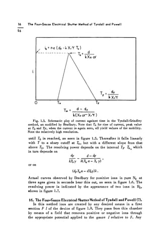
16 The Four-GauzeElectrical Shutter Method of Tyndall and Powell
§6
k(XaOT-XrY)
F i g . 1.5. Schematic plot of current against time in the Tyndall-Grindley
method, a s modified by Bradbury. Note that 7a for rise of current, peak value
at 7q and Tp, when the current i s again zero, all yield values of the mobility.
Note the relatively high resolution.
until T0 is reached, as seen in figure 1.5. Thereafter it falls linearly
with T to a sharp cutoff at Ta, but with a different slope from that
above T0. The resolving power depends on the interval Tp Ta> which
in turn depends on
dp d — dp
kX^y~ K ^ a - X r y ) '
or on
(dFXaa - dX,y)k.
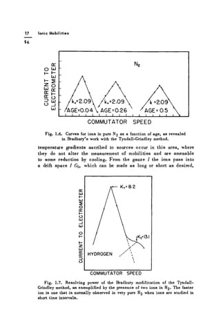
Actual curves observed by Bradbury for positive ions in pure N2 at
three ages given in seconds bear this out, as seen in figure 1.6. The
resolving power is indicated by the appearance of two ions in H2,
shown in figure 1.7.
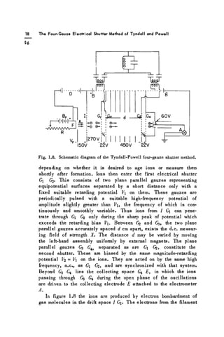
§6. The Four-Gauze Electrical Shutter Method of Tyndall and Powell (7).
In this method ions are created by any desired means in a first
section F I of the device of figure 1.8. They pass from this chamber
by means of a field that removes positive or negative ions through
the appropriate potential applied to the gauze I relative to F. Any
39.
17 Ionic Mobilities
«6
Fig.1.6. Curves for ions in pure N2 as a function of age, as revealed
in Bradbury's work with the Tyndall-Grindley method.
temperature gradients ascribed to sources occur in this area, where
they do not alter the measurement of mobilities and are amenable
to some reduction by cooling. From the gauze I the ions pass into
a drift space I G, which can be made as long or short as desired,
Fig. 1.7. Resolving power of the Bradbury modification of the Tyndall-
Grindley method, as exemplified by the presence of two ions in H2 . The faster
ion is one that is normally observed in very pure H2 when ions are studied in
short time intervals.
40.
T h eF o u r - G a u z e Electrical Shutter Method of T y n d a l l and P o w e l l
o
a
o
r - ^ l ' I ^ P - i e
- v W V A A A A '
R
G|! LÖ2 J Sä
VF-
J 2 7 0 V J J
150V 22V
•14
;G4
I ®-LE
¿L
60V
450V 22V
Fig. 1.8. Schematic diagram of the Tyndall-Powell four-gauze shutter method.
depending on whether it is desired to age ions or measure them
shortly after formation. Ions then enter the first electrical shutter
G G2. This consists of two plane parallel gauzes representing
equipotential surfaces separated by a short distance only with a
fixed suitable retarding potential V on them. These gauzes are
periodically pulsed with a suitable high-frequency potential of
amplitude slightly greater than Vi, the frequency of which is con-
tinuously and smoothly variable. Thus ions from 1 Gi can pene-
trate through Gj only during the sharp peak of potential which
exceeds the retarding bias V. Between 62 ^3» the t w o plane
parallel gauzes accurately spaced d cm apart, exists the d.c. measur-
ing field of strength X. The distance d may be varied by moving
the left-hand assembly uniformly by external magnets. The plane
parallel gauzes G3 Gi y separated as are Gi Gjj, constitute the
second shutter. These are biased by the same magnitude-retarding
potential V2 = V on the ions. They are acted on by the same high
frequency, a.c., as Gi G2, and are synchronized with that system.
Beyond G3 G4 lies the collecting space G4 E, in which the ions
passing through G3 G4 during the open phase of the oscillations
are driven to the collecting electrode E attached to the electrometer
A.
In figure 1.8 the ions are produced by electron bombardment of
gas molecules in the drift space I G. The electrons from the filament
41.
Ionic M ob i l i t i e s
F are speeded up to ionizing energy in F I, which is narrow, and
ionize in 7 Gi. The potentials are arranged as for positive ions.
This source could be replaced for positive alkali ions by a hot anode
source using an alkali ion emitter in the place of F, or by a high-
frequency glow discharge between electrodes placed in a vertical
plane where F is placed in the diagram. The field F I would then
serve as an extracting field, and / Ci as a drift space, either for
alkali ions or glow-discharge ions. Little imagination is needed
to substitute any other convenient ion source. The fields, especially
in Gi G3, are maintained uniform by having the region surrounded
by equipotential vanes connected to a high-resistance tower. Recorded
is the current to E as a function of either the frequency of the master
oscillator or as a function of the distance d between (¡2 and G3.
In analyzing the results to be expected, the shutters Gi G2 and
G3 G4, with their separation between gauzes of some 2 mm, must
be regarded. There is undoubtedly interpénétration between the
retarding fields Gj G^ and G4 with the bordering fields F G,
G3, and G4 E. These may in some measure be asymmetrical,
so that at the instant when the ions can enter Gj or G^ at the phase
when the impressed a.c. exceeds the bias, the entering ions do
not start from the same planes in both shutters. Such delays may
not be serious, and definitely will not seriously affect the peak
of the current transmitted. The shutter Gj G^ begins to open at
a time 0. It remains open, drawing ions in increasing measure over
an interval A 7/2, while the a.c. rises to a peak. It continues to
transmit with decreasing amplitude in the decline of the a.c. during
another A7/2. In this varying a.c. peak pulse of length A 7 the ions
enter and cross the distance Gj G^ of the grids, the current pulse
declining to 0 as the end of A 7 is approached. At this time, then,
a sort of bell-shaped distribution of ion densities has passed through
and lies in front of G2. It then proceeds to cross to G3, distant d
cm under the field X.
If, on arrival of the front of this pulse at G3, the time 7Q of one
complete oscillation of the a.c. has elapsed since the beginning
of A 7 at Gi, the slab will be transmitted through G3 G4, except
for losses caused by diffusion. It will then find itself just outside
of G4 and will go to E. Thus, varying either T or d will give a
series of fluctuating currents at E, possibly of rather asymmetrical
form, with clearly defined peaks, but of similarity such that 7 or
d corresponding to two equivalent points can readily be picked off
of the curves with precision. As 7 is decreased or the frequency
N is increased, the ions which just crossed at the lowest frequency
42.
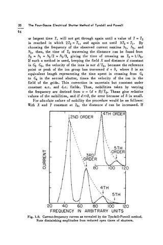
20 T he F o u r - G a u z e Electrical Shutter Method of T y n d a l l and P o w e l l
or largest time 7, will not get through again until a value of 7 = 72
is reached in which 272
=
7l f and again not until 3?3 = 7j. By
choosing the frequency of the observed current maxima Aj, A2, and
A3, then, the time of 70 traversing the distance can be found from
Aq = Ni = A2/2 = A^/3, giving the time of crossing as 70 = 1/A0 .
If such a method is used, keeping the field X and distance d constant
in (¡2 C3, the velocity of the ions is not d/T0, because the reference
point or peak of the ion group has traversed d + 8, where 8 is an
equivalent length representing the time spent in crossing from G3
to G4 in the second shutter, times the velocity of the ion in the
field of the grids. This correction is uncertain but constant under
constant a.c. and d.c. fields. Thus, mobilities taken by varying
the frequency are derived from v = (d + S)/70. These give relative
values of the mobilities, and if d»S, the error because of S is small.
For absolute values of mobility the procedure would be as follows:
With X and 7 constant at 7q, the distance d can be increased. If
FREQUENCY IN ARBITRARY UNITS
Fig. 1.9. Current-frequency curves as revealed by the Tyndall-Powell method.
Note diminishing amplitudes from reduced open times of shutters.
43.
21 I on i c M o b i l i t i e s
56
a peak occurred at d=x0 at 7g, then new peaks will occur at x,
x2, such that with constant v the distances are related by v =
(xo + 8)/7o = («1 + S)/27o = («2 + 8 ) / 3 T 0 . From the relations between
the measured values of XQ, X, XI, and the resulting relations
2x0 + 2S = x j + 5, 3 * ! + 38 = 2x2 + 25, x1 - 2x0 = 8, 2X2 - = 8,
the value of 8 can be determined. With 8 evaluated for a given set
of conditions, correction can be made to give the true value of v
by adding 8 to XQ and dividing by TQ. The Bristol group usually
varied A or 7 and evaluated v and k in relative measure. Where
absolute values wer" required, their apparatus was calibrated for
these by determining 8. The technique used in which /
V or T is
varied gives a series of peaks to which the Bristol group refers
as " o r d e r s " of the ion-mobility spectrum. Figure 1.9 shows such
a spectrum, as observed by Tyndall and Powell.
It is to be noted from the curves that the successive orders of
the peaks with constant d and varying N decrease in amplitude,
but that the peaks are clearly defined. This decrease results from
the decrease in length of the A T , the open time of the shutters,
with decreasing 7 , which reduces the current transmitted. The use
of successive orders can assist in fixing 7 accurately, though one
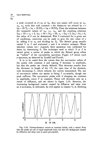
peak suffices. The successive peaks with d changing are constant
in amplitude, since T is constant. These will decrease only as a
result of diffusion, and are shown in figure 1.10. However, the
increasing background current caused by diffusion and stray ions
as d increases, is indicated. As will appear in chapter V, A. Doehring
X IN CM.
Fig. 1.10. Current-distance curves at constant fields, with x varied. Note
that the peaks are all of equal amplitude here, but that the background caused
by diffusion and stray ions is quite perceptible.
44.
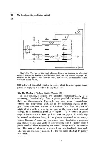
The Bradbury-Nielsen ShutterMethod
Fig. 1.11. The use of the Loeb electron filters as shutters for electron-
velocity studies by Bradbury and Nielsen. Note that this method employs two
shutters as in Tyndall and Powell's work, but the a.c. is transverse to the
direction of ion motion.
(77) achieved beautiful results by using short-duration square wave
pulses in applying the method to negative ions.
§7. The Bradbury-Nielsen Shutter Method (8).
In this method, electrons are liberated photoelectrically, or if
necessary, thermionically, from a plane parallel electrode. Where
they are thermionically liberated, one must avoid space-charge
effects and temperature gradients in the measuring region of the
gas. These electrons proceed in a uniform field from the plate of
origin B at a uniform velocity, as soon as they reach their terminal
energy, to a collecting plate A of figure 1.11. A series of guard
rings F maintains a uniform gradient over the gap A B, which may
be several centimeters long. At two planes, separated an accurately
known distance d apart, are two plane, thin, insulating supporting
ring frames which have grids of appropriately sized, equally spaced
plane parallel wires traversing the areas through which the carriers
run. The sets of wires on a given frame are insulated from each
other and are alternately connected to the two sides of a high-frequency
oscillator.
26
Schneider & Co.
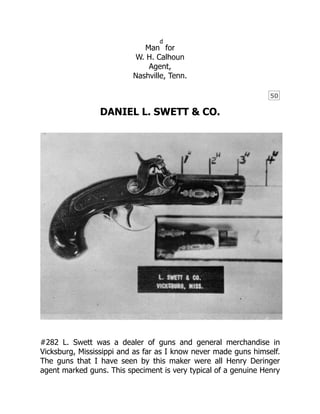
Memphis,Tenn.
SCHNEIDER & COMPANY
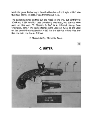
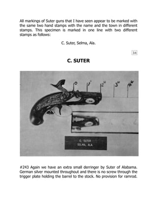
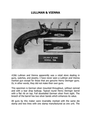
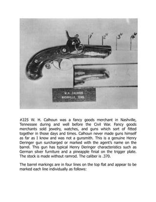
#267 This Schneider derringer is the third or fourth Southern made
gun that I obtained fifteen years ago. My good friend Horace Tolliver
of Manchester, Tennessee, had the gun. Remember that this
Schneider is made with a regular trigger guard instead of the sheath
trigger guard. The inlays and guard have no engraving with line
engraving only on the trigger plate. Semi-formed bird head grip with
47.
27
a tear dropGerman silver butt plate. Notice how low the hammer is
on the gun. Someone in years gone by attempted to dress up the
gun by checkering the forearm; but of course this hurt it some. The
nose of the forearm is fluted. There is no screw through the trigger
plate holding the barrel in place. This barrel is not octagon, but
instead is a round barrel with a rib on top similar to all those made by
Henry Deringer. Steel dovetailed front sight. Caliber is .440.
Marked on the top barrel flat with one two line hand stamp as
follows:
Schneider & Co.
Memphis, Tenn.
FREDERICK G. GLASSICK
48.
#214 This Glassickderringer is German silver mounted throughout
and has a standard derringer style trigger guard. Through the trigger
plate at the finial is a metal screw that attaches the plate to the
barrel which is doubly held in place by another screw through an
escutcheon under the forearm into the barrel. Made without wedge.
The lock has the pronounced downward curve. Full octagon barrel.
Butt is flat with an oval German silver inlay without capbox.
Checkering is rather coarse. The German silver blade front sight is
milled into the barrel. Caliber is .400.
Marked with one hand stamp in one line on the top barrel flat. The
barrel is so short and the one line is so long that part of the name is
on the breech-plug on this particular gun. The same hand stamp was
49.
28
used to mark#209 as was used on this one and is worded as
follows:
F. Glassick & Co., Memphis, Tenn.
Glassick was a gunsmith circa 1850, whose name is found stamped
on imitation derringer pistols. About 1859 he entered into a
partnership to form Schneider and Glassick.
FREDERICK G. GLASSICK
#209 Glassick derringers are in high demand like the Griswold and
Greer Confederate revolver, though they are relatively easy to get,
but command a good price. I suppose it is because Glassick and
50.
29
Schneider are sowell known that they will bring more money than
some of the lesser known derringers.
This version is a real work of art in some respects. All inlays are of
sterling silver. This model is made with a ramrod and with an oval
sterling silver butt cap with cap box built in. Although this gun shows
75% original varnish, in the past the grip has been broken into two
pieces and is carefully repaired with an inlay all the way around. To
make this grip inlay required a great deal of efficiency on the part of
the person that did it because it is just absolutely perfect the way
that it is put in with steel screws. Then the forearm apparently is
cracked underneath the wide inlay that is highly engraved. These two
silver inlay repair jobs, in my opinion, add quite a bit of value to the
gun because of their beauty and quality of workmanship. This gun
has a full octagon barrel and its breech is gold banded. The front
sight has a steel dovetailed base with a sterling silver blade. The lock
may not be curved as much as other Memphis guns, but it does have
the low profile hammer. Glassick derringers are not serial numbered.
This beautifully executed piece is a real man stopper in that its
caliber is .510. I obtained this gun from Bernie Braverman of
Pittsburgh, Pennsylvania about 1959 at a Columbus, Ohio gun show.
Marked on the top barrel flat with one hand stamp as follows:
F. Glassick & Co., Memphis, Tenn.
FREDERICK G. GLASSICK
51.
#210 This isthe second Southern made derringer that I had in my
collection and this is one that I obtained in Jackson, Mississippi.
Notice that it has a bag type grip and the lock plate is not very deeply
curved. Has standard trigger guard and the nose of the forearm is
fluted. The full octagon barrel is not serial numbered and has a dove
tailed steel base front sight with a German silver blade. Hammer sets
rather high. Through the trigger guard plate is attached one screw
that holds the barrel in place and then on the forearm forward is
another screw plate holding the screw in position that attaches the
forearm to the barrel in the second position. Caliber is .510.
The markings on this top flat of the barrel on this gun are in two lines
with letters about the same size as my other specimens. The
markings are as follows:
F. Glassick & Co.
Memphis, Tenn.
52.
30
FREDERICK G. GLASSICK
#211My first Southern derringer was this Glassick derringer that I
obtained at one of the early Jackson, Mississippi gun shows about
fifteen or sixteen years ago. My good friend Nathan Swazy brought
the gun in and I traded him two old Civil War swords and a Colt
pistol. You cannot tell it now, but the forearm was shattered and my
good friend Frank Hitchings of Memphis replaced the forearm in such
a manner that the joint in the new wood cannot be distinguished
from the old. This gun is German silver mounted throughout and has
a fluted forearm nose. There are two screws holding the barrel in
position through the trigger plate and the nice escutcheon under the
forearm. Flat butts are rather common to many of the Memphis and
53.
31
Nashville guns. Fulloctagon barrel with a brass front sight milled into
the steel barrel. Its caliber is a tremendous .510.
The barrel markings on this gun are made in one line, but contrary to
#209 and #214 in which case one stamp was used, two stamps were
used on this one. “F. Glassick & Co.” is a different stamp from
“Memphis, Tenn.” The same stamps were used on #210 as are used
on this one with exception that #210 has the stamps in two lines and
this one is in one line as follows:
F. Glassick & Co., Memphis, Tenn.
C. SUTER
54.
32
#274 Little isknown about this maker, Suter. No guns made by Henry
Deringer with Suter’s name on the barrel are known.
This particular piece is a small size and has characteristics of styling
that make it desirable. It is German silver mounted throughout with a
pineapple finial on the trigger plate. There is no screw through the
trigger plate holding the barrel in position. The wedge and the tang
screw are the only attachments to the barrel. No provision for
ramrod. Round barrel has rib at top flat. The front sight is German
silver dovetailed and the rear of the barrel has two gold bands which
enhances its value. The condition of the gun is extra nice with real
sharp original checkering. The extra thin barrel at the muzzle is
caliber .42.
The barrel is marked on the right hand side below the top flat “steel.”
The top flat of the barrel is marked in two lines with two different
hand stamps as follows:
C. Suter,
Selma, Ala.
C. SUTER
55.
33
#4 This isa photograph of a genuine Wurfflein Deringer made in
Philadelphia. The sideplate of German silver is absolutely identical to
those of most Suter Deringers. This will leave some room for thought
that Suter Deringers are made by Wurfflein. Notice there is some
similarity in the shape and contour of this Suter #274 and the
illustrated Wurfflein. Both of these guns are often but not always
marked with the word “steel” on the right hand barrel flat
immediately below the top flat but always with different size stamps.
C. Suter,
Selma, Ala.
56.
C. SUTER
#264 Ihave seen Suter derringers in many sizes and this is about as
large as they come. Although the barrel is slightly over 4”, other
derringer makers made them even longer. The stock is German silver
mounted and has provision for a ramrod. The buttcap is a German
silver rosette held in place by a steel wood screw. Typical derringer
German silver trigger guard with pineapple finial. Suter was good at
copying Henry Deringer’s trigger guard. Two gold bands are at the
breech of the barrel and the front sight is completely made of
German silver that is dovetailed into the flat. Barrel is round with a
rib at the top. Caliber is .410.
57.
34
All markings ofSuter guns that I have seen appear to be marked with
the same two hand stamps with the name and the town in different
stamps. This specimen is marked in one line with two different
stamps as follows:
C. Suter, Selma, Ala.
C. SUTER
#243 Again we have an extra small derringer by Suter of Alabama.
German silver mounted throughout and there is no screw through the
trigger plate holding the barrel to the stock. No provision for ramrod.
58.
35
Round barrel hastwo bands at the breech in gold and in silver with a
dovetailed German silver front sight.
The barrel is marked on the right hand side below the top flat “steel.”
The barrel is marked in two lines on the top flat as follows:
C. Suter,
Selma, Ala.
HORACE E. DIMICK & CO.
59.
36
37
#272 H. E.Dimick of course is so well known that a description of his
history of operations is not necessarily of interest in this little book
but we are going to use it anyway. In the course of several years of
collecting, I have seen no less than 10 or 12 H. E. Dimick derringers,
all with the same type of small markings on the top barrel flat.
Invariably the lock plates are not marked but do have a floral pattern
engraved in place. They are always long and slender and are not
large guns and are not heavy. This piece is made without ramrod and
with German silver mountings throughout. The trigger plate finial is in
the shape of a pineapple. The barrel has a brown twist steel imitation
finish. The German silver front sight is milled into the barrel and is
not dovetailed. Caliber is .390.
The barrel is marked on the top flat at a slight angle showing hand
stampings with one die stamp and one line as follows:
H. E. Dimick
This name will be noted in all of the 1859 Saint Louis City Directories.
Dimick was probably the best known and prolific of all the secondary
St. Louis riflemakers and his guns stood on their own reputation. He
came from Kentucky to establish the St. Louis Gun Shop at 38 North
Main Street in 1849. From 1849 through 1864, the firm was known as
H. E. Dimick & Co. From 1865 until Mr. Dimick’s death in 1873 the
listing was simply H. E. Dimick. Thus, here is a clue towards dating
your guns with this mark.
There has been a great deal of confusion about the associates in the
H. E. Dimick & Co. plant. Henry Folsom may have been a partner for
a few years; he was at least important enough in the firm to be listed
along with H. E. Dimick in a City Directory.
F. J. BITTERLICK
60.
#261 Contrary tomost derringers made in the South, Bitterlick
marked his on both the barrel and the lock. All furniture is of plain,
not engraved, German silver and the escutcheon plate under the
forearm embraces the screw that attaches the forearm to the barrel.
The forearm nose is fluted. The barrel is full octagon, and its caliber
is .400.
The markings are to be found identically on the lock and the barrel in
two lines with one hand stamp marked as follows:
Fr. J. Bitterlick
Nashville, Tenn.
Franz J. Bitterlick was born July 16, 1829 and died July 12, 1880 at
51 years and 6 days old. His daughter Ann Elizabeth married Charles
Evers and their descendents and great grandchildren are living in
Nashville today, 1971.
61.
38
Joseph Legler wasborn October 21, 1837 and died June 15, 1931 at
the age of 93 years and 8 months. His descendents by the name of
Legler still live in Nashville today.
Franz Bitterlick and Joseph Legler were brothers-in-law, having
married sisters Mary and Helen Lochmann respectively.
There is no record of when Bitterlick first started operating but
if he was born in 1829 and started the business when he was
25 years old, that would mean that the Bitterlick Company started
about 1854.
The first record of a business using either of these two names is
found in King’s City Directory of 1867, the earliest available, and is
listed as Bitterlick & Legler, Gunsmiths, 22 Deaderich Street. No City
Directories are available before 1867 so it is entirely possible that the
combination of the two names originated before that date.
Considering that in 1867, Legler was 30 years old and considering the
point that he could have been a partner of Bitterlick as early as 25
years of age means that the Bitterlick & Legler Company could have
started around 1862.
In an interview in 1970 with Mr. Bernard Evers, Sr., the grandson of
Bitterlick, he stated he believed the gunsmith business started in
1854, give or take a year, and that Bitterlick made himself scarce
during the War Between the States by taking a four year “Round the
World” trip.
All in all it would average up that the company of Bitterlick operated
from perhaps 1854 to 1862 or 1865.
Bitterlick and Legler without a doubt operated from 1862-65 til the
last listing of the combination company in the King’s City Directory of
1879.
62.
39
In 1880 JosephLegler is listed as a gunsmith and Frank Bitterlick as a
grocer at two different addresses.
Thus from these dates that we have accumulated here you can tell
approximately when your gun was made according to the name on
the barrel, and that no derringers were produced after 1879 because
none are known marked “Legler.”
According to a news clipping dated March 1, 1963 of the Nashville
Tennessean newspaper, the J. Legler, Gunsmith business was sold on
that date and it is noted that the operation was started 95 years ago
on Deaderich Street which would make the business starting in 1868.
To me this does not quite add up since the City Directories state that
they were operating in 1867. I would say that the business started
sometime between 1854 and 1867.
Joseph Legler is buried in the Mt. Olive Cemetery near Nashville,
Tennessee.
It is interesting to note that the Legler descendents with the same
name operated this business as a gunsmith at 321 Deaderich Street
until December 31, 1962 when the business was closed out. The
building was sold to a real estate agent on March 1, 1963.
All their pistols were high quality. In addition to derringer type pieces
it is known that Bitterlick produced and manufactured shotguns and a
few target rifles marked “FR. J. Bitterlick & Co., Nashville, Tenn.”.
Early double breechloading shotguns with outside hammers are
known that are marked “J. Leghler, Nashville, Tenn.” and will you
please note the new spelling of Legler in this later breechloading
period.
F. BITTERLICK
63.
40
#285 This isa small sized derringer by any standards and is made by
Bitterlick. I have never seen a Bitterlick smaller than this one. This
gun also has the escutcheon screw plate underneath the forearm
attaching that part to the full octagon barrel. The forearm nose is
fluted as is common to many of these Nashville and Memphis guns.
All furniture is of German silver and is plain, not engraved.
The barrel markings are slightly different from #261 in that the
expression “& Co.” has been added as follows:
Fr. J. Bitterlick & Co.
Nashville, Tenn.
{FOOT-POWERED LATHE}
64.
41
#285A This isa real old foot powered metal turning lathe that is in
our collection here at Dixie Gun Works. It was obtained from the
current Snodgrass Gun Shop in Nashville and Mr. Snodgrass states
that many, many years ago he got it from the old Legler Gun Shop.
There is an awfully good chance that parts such as screws for the
Bitterlick or Bitterlick & Legler Derringers were made on this same
lathe. Incidentally, Hal Swann of Nashville has a large quantity of
Bitterlick or Bitterlick & Legler tools such as files, bullet mould
cherries, screwdrivers and even a die stamp reading “Bitterlick & Co.”
This die stamp is not the same one that is used on the derringers
though. This die stamp has never been seen on a gun.
65.
LULLMAN & VIENNA
#266Lullman and Vienna apparently was a retail store dealing in
guns, watches, and jewelry. I have never seen a Lullman and Vienna
marked gun except for those that are genuine Henry Deringer guns.
Or, in other words, they did not make their own guns.
This specimen is German silver mounted throughout, without ramrod
and with a tear drop buttcap. Typical round Henry Deringer barrel
with a flat rib on top. Full dovetailed German silver front sight. The
breech of the barrel has two silver bands which enhances its value.
All guns by this maker were invariably marked with the same die
stamp and two lines with one stamp manufactured as one unit. The
66.
42
stampings reads asfollows:
Lullman & Vienna,
Memphis, Tenn.
LULLMAN & VIENNA
#258 A very desirable sized derringer with a short barrel and many
people call this the Abe Lincoln model which is true except for the
marking on the barrel. This gun is German silver mounted
throughout, and made without ramrod. Solid German silver front
sight is dovetailed into position. The rear of the barrel has two silver
67.
43
bands. Has typicalHenry Deringer markings on the lock and on the
breechplug. The caliber is .410.
The barrel markings are typically as follows:
Lullman & Vienna,
Memphis, Tenn.
LULLMAN & VIENNA
#254 An even smaller sized Lullman and Vienna derringer is this
genuine Henry Deringer gun that is marked with this agent’s name on
the barrel. German silver throughout and you will notice that this gun
68.
44
does not havea ramrod like all the others by this same maker in my
collection. I wonder if all were sold to Lullman and Vienna without
ramrods? Solid German silver front sight dovetailed in place along
with two silver barrel bands at the breech. Its caliber is .380.
The barrel markings are typically as follows:
Lullman & Vienna,
Memphis, Tenn.
BITTERLICK & LEGLER
69.
45
#262 This Bitterlickspecimen is typical of his earlier guns except for
the later markings on the barrel. The full octagon barrel is held in
place by two screws through the forearm and through the trigger
plate directly into the barrel. The escutcheons and furniture are all of
plain German silver with no engraving whatsoever. Has German silver
pin type front sight with gold band at the breech. The breech is
marked with the number “I.” All metal parts show old milling marks
and file marks because of its excellent condition. Caliber is .470.
The identical markings are to be found on both the barrel and the
lock and two different hand stamps are used as follows:
Fr. J. Bitterlick & Legler
Nashville, Tenn.
STEPHEN O’DELL
70.
#222 O’Dell gunsare often times easily recognized by their
characteristic European influence. The grips are a little different in
this shape gun in that they are the flat bag type instead of a rounded
bag type which is more of an English style than American. The round
faced hammer does not follow the characteristics of Southern
derringers. All furniture is of German silver and of the highest quality
casting and are fully engraved with English line scroll engraving. The
trigger plate has a pineapple finial and through the trigger plate is
the typical Southern style screw that attaches the forearm to the
barrel along with the barrel being held in place by a wedge.
I need to mention that there are several known Henry Deringer made
guns that are marked in one line on the barrel and with a hand stamp
71.
46
47
“S. O’Dell.” Inthis specimen that we present here that is marked on
the lock plate, the name is hand engraved in and is not stamped.
This ornate specimen has five gold and silver bands at the
breech. The barrel is rounded with a rib flat on top. The silver
front sight is machined into place. The lockplate is filed down to fit
the wood with more of a cross curve than Henry Deringer guns show.
The caliber is unusually small, it being only .330.
This gun is marked on the lock only as follows:
S. O’Dell
O’Dell came from New York State probably in the late 1830’s or early
1840’s and according to newspaper accounts of that period was
murdered in the early 1860’s at Natchez. Although his derringers had
bag shaped grips and not bird head grips, I am classifying them as a
derringer rather than a pocket pistol. Halfstock rifles with his name
are known.
SCHNEIDER & GLASSICK
72.
#215 Schneider andGlassick derringers have characteristics of both
of these earlier companies that merged to form this one. All furniture
is very plain German silver without even the least line engraving.
There is a screw through the trigger plate holding the barrel into
position along with the typical wedge. The full octagon barrel is
rather plain with no embellishments at the breech. The caliber is
.450.
The markings are in one line with one stamp on the top flat of the
barrel as follows:
Schneider & Glassick, Memphis, Tenn.
Schneider & Glassick, gunsmiths, formed about 1859 by William S.
Schneider and Frederick G. Glassick, both of whom had previously
operated independently. They early secured a Confederate contract to
manufacture revolvers, this being in addition to the repairing of other
73.
48
types of firearms.They advertised in March, 1862, advising persons
who had left “guns or pistols longer than three months” to call, as
they intended delivering all such arms to the Confederate
government as of March 15th.
Shortly after this advertising date of March 7, 1862, Memphis was
evacuated by all Confederate Ordnance activities, and the firm was
not heard from again.
SCHNEIDER & GLASSICK
74.
49
#6 Although indeplorable condition, this Schneider and Glassick can
be restored and I am going to spend upwards of $200 to have the
trigger guard and the hammer made new. Notice the extra long
length of the grip and of the bird head shape. The barrel is held in
place both by a trigger plate screw and a wedge. The front sight is a
brass blade milled into the steel barrel with no engraving or
ornamentation at the breech. Notice the heavy downward curve of
the lock. Caliber is .500.
The barrel markings are done with the same stamp as used on gun
#215 which is a one piece stamp in one line as follows:
Schneider & Glassick, Memphis, Tenn.
W. H. CALHOUN
75.
#225 W. H.Calhoun was a fancy goods merchant in Nashville,
Tennessee during and well before the Civil War. Fancy goods
merchants sold jewelry, watches, and guns which sort of fitted
together in those days and times. Calhoun never made guns himself
as far as I know and was not a gunsmith. This is a genuine Henry
Deringer gun surcharged or marked with the agent’s name on the
barrel. This gun has typical Henry Deringer characteristics such as
German silver furniture and a pineapple finial on the trigger plate.
The stock is made without ramrod. The caliber is .370.
The barrel markings are in four lines on the top flat and appear to be
marked each line individually as follows:
76.
50
Man
d
for
W. H. Calhoun
Agent,
Nashville,Tenn.
DANIEL L. SWETT & CO.
#282 L. Swett was a dealer of guns and general merchandise in
Vicksburg, Mississippi and as far as I know never made guns himself.
The guns that I have seen by this maker were all Henry Deringer
agent marked guns. This speciment is very typical of a genuine Henry
77.
51
52
Deringer such aswith ramrod, German silver furniture, and pineapple
finial on the trigger plate.
The barrel markings are in three lines and it appears to be one stamp
because each line is so perfect when compared with the other. The
markings are as follows:
Made for
L. Swett & Co.
Vicksburg, Miss.
This name represents an agent primarily since no guns not of Henry
Deringer manufacture are known. Newspaper advertisements of that
period show he operated in the late 1850’s. It is interesting to notice
that Mrs. Jefferson Davis carried a Swett derringer in her purse. The
gun is now on display in the old capitol museum in Jackson,
Mississippi.
J. A. SCHAFER
J. A. Schafer. Vicksburg, Mississippi, is one gun that I do not have
and I would like to obtain. I have heard of three of these guns and
they are always Henry Deringer guns surcharged with this agent’s
name and without a doubt all will be typical of Henry Deringer
manufactury.
L. F. TRUMPLER
78.
53
#204 Trumpler ofLittle Rock does not make a gun that looks like a
Henry Deringer or a Southern Derringer. His guns are entirely
different. Notice the funny nosecap, the tall hammer, and the extra
narrow trigger guard and trigger plate. Although the trigger plate
ends in a finial of a pineapple, it is not a Henry Deringer type of
pineapple. This derringer has a silver band at the breech with a small
amount of engraving. The barrel is round with a rib on top. Its caliber
is .430.
The only markings are on the barrel as follows in one line:
L. F. Trumpler, L. Rock, Ark.
79.
#278 J. B.Gilmore, Shreveport, Louisiana, produced guns by his own
hand and he also used Henry Deringer guns that were surcharged
with his own name. This particular gun is rather slender and it has a
nice appealing style, it being manufactured by Gilmore himself. Notice
the turned down forearm nose. The gun is mounted with German
silver furniture lightly engraved. The barrel is round with a flat rib on
top. Its caliber is .380.
The only markings are on the top of the barrel flat as follows:
J. B. GILMORE
Jerome Bonaparte Gilmore was born in Jefferson County, Kentucky, in
1827, and came to Shreveport, La. in 1849. There is a strong
possibility that he was the son of J. Gilmore, of the firm J. Gilmore
and Moses Dickson, Gunmakers, of Louisville (1848-1860), as,


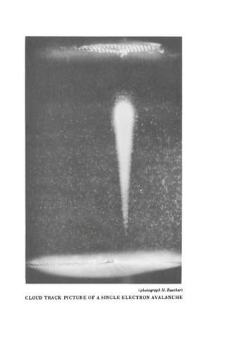


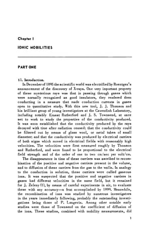
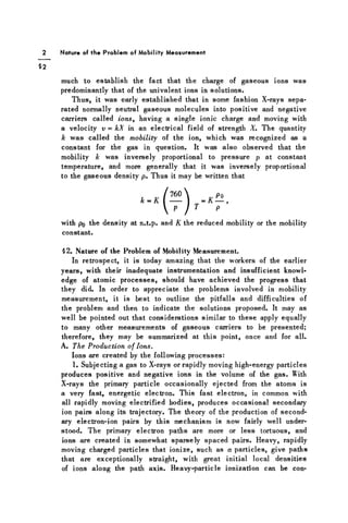
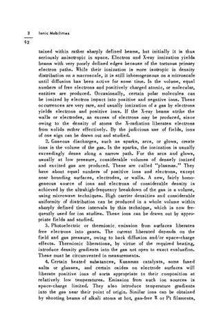
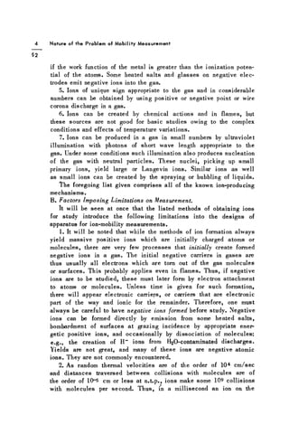
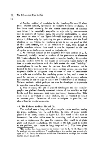
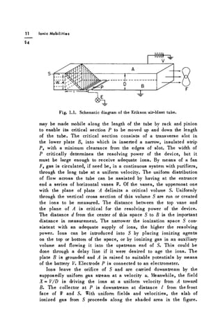
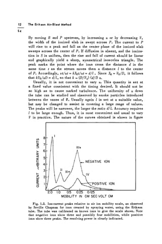
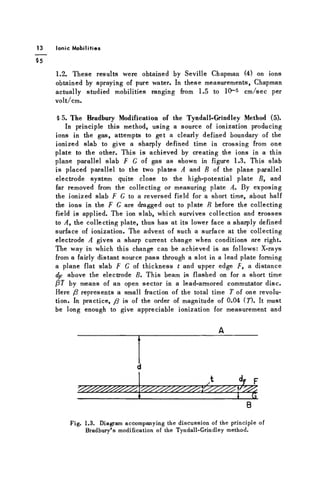
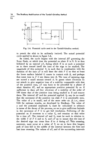
![Ionic M o b i l i t i e s
87 and eT, were chosen by Bradbury to be about equal to 0.32 7.
In practice Vr was made 10 to 20% greater than Va. Actually, from
the reasoning to follow, it is a simple matter to figure properly
the values of y, a, Vr, and Va from the necessary width of F G and
F B. During aT, in the event that the ions of opposite sign, e.g.,
electrons, were not removed in 6T, the ions of opposite sign will
all be drawn to B and can be neglected in further considerations.
The phase ST with a potential Vr draws residual ions that did not
reach A during aT back to B, thus clearing the gap to prepare for
the next cycle after a period eT, during which B is at 0 potential.
The purpose of the cyclical arrangement using a commutator lies
in sending successive batches of ions to yield an easily measured
current to A. X-ray ionization is limited in density and /3T is neces-
sarily short, so that the few ions in the slab are multiplied by A' =
1 / 7 per second, giving a relatively comfortable current to measure.
The theory of the method is as follows: The cycle may be regarded
as keeping a, /3, y, S, e, and d, as well as Vr and Va and their cor-
responding fields X^ and Xa, constant, and only varying T. Starting
with a large value of T, all ions will be swept to B until T is reduced
to the point Tp, at which with a mobility k it follows that kX^Tp^dp,
or the distance F B. If, then, X^ and a have been correctly chosen,
and the distance from B to A be designated as d, it will be assumed
that ~kXaaTp> d, so that ions surviving capture by B during yT can
reach A. At Tp, then, a current begins to be registered per cm2
of A, which may be written as i = neidp —kXryT). This consists
of all the n ions per cm3
which escape capture by B and now reach
A. As T is still further decreased, and with a proper choice of values
of fields and pulse lengths, a time 70 will be reached, at which
during aT all the ions that escaped capture at B just cease to be
able to reach A. This occurs when A;A^a7o = d. This represents
a peak in the value of i. After this, i is determined by the width
of the surviving ions in F G between the top F of the band, at d—
(dp — kX,y.T) from A, down to a distance <4 = kXgoJ from A, which
marks the lowest ion group toward B which can reach A in T with
T < 70. The current then is
i = ne [<4 -d - dp - kXT y 7j] = ne [.dp + k{Xaa - Xry)T - d.
The current i thus decreases linearly with decrease in the time 7
to 7 = 7a, at which time the current i equals 0. At this point, solution
of the equation for ¿ = 0 evaluates 7a as Ta= d — dp/k.(Xaa - X f y
It is seen that except for diffusion effects as 7 decreases, the cur-
rent rises sharply at a well-defined time Tp and is linear with 7](https://image.slidesharecdn.com/120434-250315085540-d9983e1f/85/Basic-Processes-of-Gaseous-Electronics-Leonard-B-Loeb-37-320.jpg)