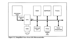
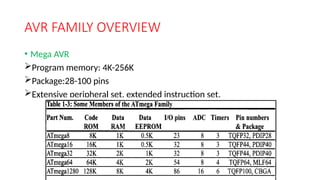
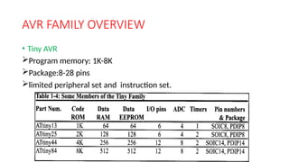
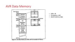
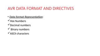
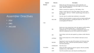
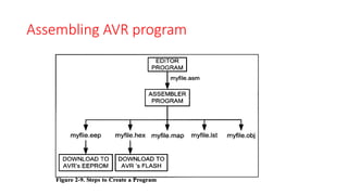
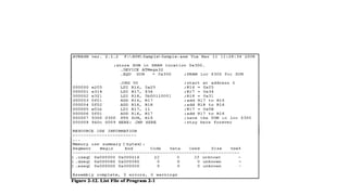
OVERVIEW OF AVR
AVR FAMILY OVERVIEW
• Classic AVR
AVR FAMILY OVERVIEW
• Mega AVR
Program memory: 4K-256K
Package:28-100 pins
Extensive peripheral set, extended instruction set.
AVR FAMILY OVERVIEW
• Tiny AVR
Program memory: 1K-8K
Package:8-28 pins
limited peripheral set and instruction set.
AVR FAMILY OVERVIEW
• Special purpose AVR
GPRs in the AVR
Conti…
AVR Data Memory
• GPRs- 2B
• IO Registers- 64B
• SRAM-(128 B to 4KB)
Conti…
Using instructions with the Data Memory
• LDS (LoaD direct from Data Space): LDS Rd, K
• STS(STore direct to data Space): STS K, Rr
AVR STATUS REGISTER
AVR DATA FORMAT AND DIRECTIVES
• Data format Representation:
Hex Numbers
Decimal numbers
 Binary numbers
ASCII characters
Assembler Directives
• .EQU
• .ORG
• .INCLUDE
Segment` Directive Description
Header
.DEVICE
Defines the type of the target processor and the applicable set of
instructions (illegal instructions for that type trigger an error message,
syntax: .DEVICE AT90S8515)
.DEF Defines a synonym for a register (e.g. .DEF MyReg = R16)
.EQU
Defines a symbol and sets its value (later changes of this value remain
possible, syntax: .EQU test = 1234567, internal storage of the value is 4-
byte- Integer)
.SET Fixes the value of a symbole (later redefinition is not possible)
.INCLUDE
Includes a file and assembles its content, just like its content would be part
of the calling file (typical e.g. including the header file: .INCLUDE "C:
avrtoolsappnotes8515def.inc")
Code
.DB
Inserts one or more constant bytes in the code segment (could be numbers
from 0..255, an ASCII-character like 'c', a string like 'abcde' or a
combination like 1,2,3,'abc'. The number of inserted bytes must be even,
otherwise an additional zero byte will be inserted by the assembler.)
.DW
Insert a binary word in the code segment (e.g. produces a table within the
code)
.LISTMAC
Macros will be listed in the .LST-file. (Default is that macros are not
listed)
.MACRO
Beginning of a macro (no code will be produced, call of the macro later
produces code, syntax: .MACRO macroname parameters, calling by:
macroname parameters)
.ENDMACRO End of the macro
Everywhere
.ORG
Defines the address within the respective segment, where the assembler
assembles to (e.g. .ORG 0x0000)
.EXIT End of the assembler-source code (stops the assembling process)
Structure OF AVR Assembly Language
Assembling AVR program
PROGRAM
COUNTER(PC)
IN AVR
Program Counter & Program ROM space in the AVR:
• Address of the next instruction to be executed.
• As the CPU fetches the opcode from program ROM, the PC is
incremented by 1, which points to the next instruction.
• Size of PC—(14 bit to 22-bit).
• In AVR microcontrollers, each flash memory location is 2-bytes
wide.
• e.g. ATMega32---> ROM size is 32KB  organized as 16KB x 2B.
ROM memory map in AVR family
Placing code in program ROM
ROM width in the AVR
AVR is word-addressable.
Harvard
Architecture in
the AVR
Harvard Architecture in the AVR:
Instruction size of the AVR
ADD INSTUCTION FORMATION
FEATURES
1. RISC processors have a fixed instruction size.
2. RISC processors have a large number of registers.
3. RISC processors have small instruction set.
4. >95% instructions are executed with only single clock cycle.
5. RISC processors have separate buses for program and data.
• In RISC, there are 4 sets of buses-
• 1) a set of data buses for carrying data (operands) in and out of CPU.
• 2) a set of address buses for accessing the data.
• 3) a set of buses to carry the opcodes.
• 4) a set of address buses to access the opcodes.
FEATURES
5.RISC uses LOAD/STORE architecture.
6. RISC instructions are implemented using hardwire method.
Hardwiring of RISC instructions takes no more than 10% of the
transistors.

AVR Microcontroller-Introduction, Features

  • 1.
  • 3.
  • 4.
    AVR FAMILY OVERVIEW •Mega AVR Program memory: 4K-256K Package:28-100 pins Extensive peripheral set, extended instruction set.
  • 5.
    AVR FAMILY OVERVIEW •Tiny AVR Program memory: 1K-8K Package:8-28 pins limited peripheral set and instruction set.
  • 6.
    AVR FAMILY OVERVIEW •Special purpose AVR
  • 7.
  • 8.
  • 9.
    AVR Data Memory •GPRs- 2B • IO Registers- 64B • SRAM-(128 B to 4KB)
  • 10.
  • 11.
    Using instructions withthe Data Memory • LDS (LoaD direct from Data Space): LDS Rd, K
  • 12.
    • STS(STore directto data Space): STS K, Rr
  • 13.
  • 14.
    AVR DATA FORMATAND DIRECTIVES • Data format Representation: Hex Numbers Decimal numbers  Binary numbers ASCII characters
  • 15.
    Assembler Directives • .EQU •.ORG • .INCLUDE Segment` Directive Description Header .DEVICE Defines the type of the target processor and the applicable set of instructions (illegal instructions for that type trigger an error message, syntax: .DEVICE AT90S8515) .DEF Defines a synonym for a register (e.g. .DEF MyReg = R16) .EQU Defines a symbol and sets its value (later changes of this value remain possible, syntax: .EQU test = 1234567, internal storage of the value is 4- byte- Integer) .SET Fixes the value of a symbole (later redefinition is not possible) .INCLUDE Includes a file and assembles its content, just like its content would be part of the calling file (typical e.g. including the header file: .INCLUDE "C: avrtoolsappnotes8515def.inc") Code .DB Inserts one or more constant bytes in the code segment (could be numbers from 0..255, an ASCII-character like 'c', a string like 'abcde' or a combination like 1,2,3,'abc'. The number of inserted bytes must be even, otherwise an additional zero byte will be inserted by the assembler.) .DW Insert a binary word in the code segment (e.g. produces a table within the code) .LISTMAC Macros will be listed in the .LST-file. (Default is that macros are not listed) .MACRO Beginning of a macro (no code will be produced, call of the macro later produces code, syntax: .MACRO macroname parameters, calling by: macroname parameters) .ENDMACRO End of the macro Everywhere .ORG Defines the address within the respective segment, where the assembler assembles to (e.g. .ORG 0x0000) .EXIT End of the assembler-source code (stops the assembling process)
  • 18.
    Structure OF AVRAssembly Language
  • 19.
  • 21.
    PROGRAM COUNTER(PC) IN AVR Program Counter& Program ROM space in the AVR: • Address of the next instruction to be executed. • As the CPU fetches the opcode from program ROM, the PC is incremented by 1, which points to the next instruction. • Size of PC—(14 bit to 22-bit). • In AVR microcontrollers, each flash memory location is 2-bytes wide. • e.g. ATMega32---> ROM size is 32KB  organized as 16KB x 2B.
  • 23.
    ROM memory mapin AVR family
  • 24.
    Placing code inprogram ROM
  • 25.
    ROM width inthe AVR AVR is word-addressable.
  • 26.
  • 27.
  • 28.
  • 33.
    FEATURES 1. RISC processorshave a fixed instruction size. 2. RISC processors have a large number of registers. 3. RISC processors have small instruction set. 4. >95% instructions are executed with only single clock cycle. 5. RISC processors have separate buses for program and data. • In RISC, there are 4 sets of buses- • 1) a set of data buses for carrying data (operands) in and out of CPU. • 2) a set of address buses for accessing the data. • 3) a set of buses to carry the opcodes. • 4) a set of address buses to access the opcodes.
  • 34.
    FEATURES 5.RISC uses LOAD/STOREarchitecture. 6. RISC instructions are implemented using hardwire method. Hardwiring of RISC instructions takes no more than 10% of the transistors.

Editor's Notes

  • #26 Advanced Microcontrollers