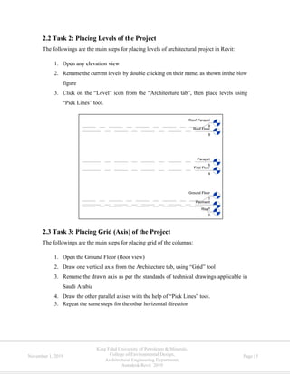
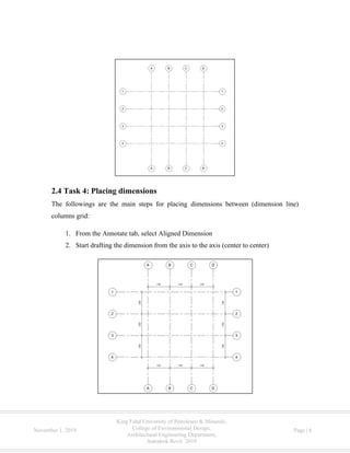
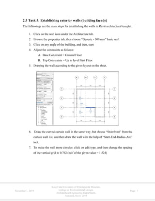
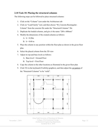
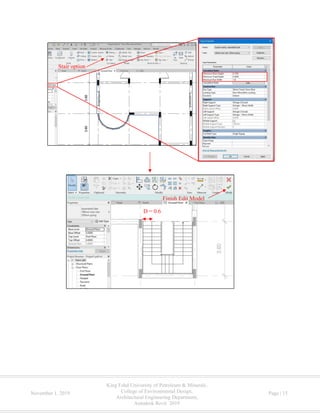
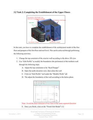
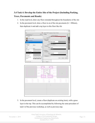
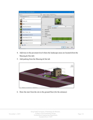
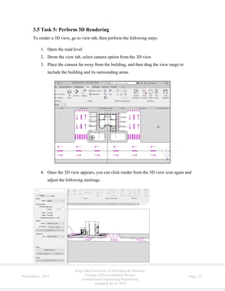
Autodesk Revit 2019
October 29 – 30, 2019
This material is a short course (workshop) developed to the Architectural Engineering
students at King Fahd University of Petroleum and Minerals, about Autodesk Revit
By:
Mohammad Basel Hamida
Graduate student, Architectural Engineering Department, College of Environmental Design (CED), King
Fahd University of Petroleum and Minerals, Dharan, Saudi Arabia
ARE Club
College of Environmental Design, Architectural Engineering Department
‫السعودية‬ ‫العربية‬ ‫المملكة‬
‫التعليم‬ ‫وزارة‬
‫جامعة‬‫للبترول‬ ‫فهد‬ ‫الملك‬
‫والمعادن‬
Kingdome of Saudi Arabia
Ministry of Education
King Fahd University of Petroleum
and Minerals
King Fahd University of Petroleum & Minerals,
College of Environmental Design,
Architectural Engineering Department,
Autodesk Revit 2019
November 1, 2019 Page | I
Summary
This document provides introduction and practical exercises regarding the utilization of
Autodesk in the Architectural Engineering domain. It consists of three main sections,
namely: introduction, workshop (I) and workshop (II). The introduction includes overview
of Autodesk Revit, outline of the curse and useful links.
Workshop (I) includes ten tasks, namely: adjustment of the project units, placing levels of
the project, placing grid (axis) of the project, placing dimensions, establishing walls
(building façade), creating new material/item from the library, establishment of interior
walls (partitions), placing a floor, placing doors and windows, and placing the structural
columns.
Workshop (II) includes six tasks, namely: establishing stairs, completing the establishment
of the upper floor, insert (import) CAD to develop the site of the project, develop the entire
site of the project (including parking, trees, pavements and roads), perform 3D rendering,
and export Revit view to Autocade file (DWG).
King Fahd University of Petroleum & Minerals,
College of Environmental Design,
Architectural Engineering Department,
Autodesk Revit 2019
November 1, 2019 Page | II
Table of Contents
Summary.........................................................................................................................................I
Table of Contents.......................................................................................................................... II
1. Introduction ............................................................................................................................... 1
1.1 Overview of Autodesk Revit................................................................................................. 1
1.2 Outline of the Course............................................................................................................. 1
1.3 Useful Links .......................................................................................................................... 3
2. Workshop (I): October 29, 2019............................................................................................... 4
2.1 Task 1: Adjustment of the Project Units ............................................................................... 4
2.2 Task 2: Placing Levels of the Project.................................................................................... 5
2.3 Task 3: Placing Grid (Axis) of the Project ............................................................................ 5
2.4 Task 4: Placing dimensions................................................................................................... 6
2.5 Task 5: Establishing exterior walls (building façade) ........................................................... 7
2.6 Task 6: Creating new material/item from the library ............................................................ 9
2.7 Task 7: Establishment of interior walls (partitions) ............................................................ 10
2.8 Task 8: Placing a floor......................................................................................................... 10
2.9 Task 9: Placing Doors and windows ................................................................................... 11
2.10 Task 10: Placing the structural columns............................................................................ 13
3. Workshop (II): October 30, 2019........................................................................................... 14
3.1 Task 1: Establishing Stairs .................................................................................................. 14
3.2 Task 2: Completing the Establishment of the Upper Floors ............................................... 16
3.3 Task 3: Insert (Import) CAD to Develop the Site of the Project......................................... 20
3.4 Task 4: Develop the Entire Site of the Project (Including Parking, Trees, Pavements and
Roads)........................................................................................................................................ 21
3.5 Task 5: Perform 3D Rendering............................................................................................ 23
3.6 Task 6: Export Revit View to Autocade File (DWG) ......................................................... 24
King Fahd University of Petroleum & Minerals,
College of Environmental Design,
Architectural Engineering Department,
Autodesk Revit 2019
November 1, 2019 Page | 1
1. Introduction
1.1 Overview of Autodesk Revit
Revit Autodesk is a multidisciplinary BIM software utilized to produce consistent,
coordinated, and complete model-based building designs and documentation. It works at
coordinating the design tools of four main disciplines, namely:
1. Architectural design
2. Structural design
3. MEP design
4. Construction
Thus, Autodesk Revit offers four templates for each of these disciplines. This course will
focus on the application and utilization of architectural design templet in the architectural
engineering profession.
1.2 Outline of the Course
This course is divided into two workshops, Workshop (I) and Workshop (II). In each
workshop, a set of exercises are going to be carried out and discussed.
In workshop #1, the following tasks are going to be conducted:
1. Adjustment of the project units
2. Placing levels of the project
3. Placing grid (axis) of the project
4. Placing dimensions
5. Establishing exterior walls (building façade)
6. Creating new material/item from the library
7. Establishment of interior walls (partitions)
8. Placing a floor
9. Placing Doors and windows
10. Placing the structural columns
King Fahd University of Petroleum & Minerals,
College of Environmental Design,
Architectural Engineering Department,
Autodesk Revit 2019
November 1, 2019 Page | 2
In workshop # 2, the following tasks are going to be conducted
1. Establishing stairs
2. Completing the establishment of the upper floor
3. Insert (import) CAD to develop the site of the project
4. Develop the entire site of the project (including parking, trees, pavements and
roads)
5. Perform 3D rendering
6. Export Revit view to Autocade file (DWG)
King Fahd University of Petroleum & Minerals,
College of Environmental Design,
Architectural Engineering Department,
Autodesk Revit 2019
November 1, 2019 Page | 3
1.3 Useful Links
The table below provides a list of tutorials in the YouTube, which would be useful to you
in the future.
Tutorial URL
Start architectural project https://www.youtube.com/watch?v=qVYloG7oZ8U
Adjust the units of the project https://www.youtube.com/watch?v=RFAHHDt_RzE
Creating axis (grid) and levels https://www.youtube.com/watch?v=oUO2ZHEKmM4
https://www.youtube.com/watch?v=uJ6hxryUjPs
Establish walls and floor/roof https://www.youtube.com/watch?v=hdgyZd_EiD4
Add openings (doors & windows) https://www.youtube.com/watch?v=Y1yYMims-fQ
Draw stairs https://www.youtube.com/watch?v=Wg7TvLgkers
https://www.youtube.com/watch?v=jBsa23sSRms
https://www.youtube.com/watch?v=6ush7rLRu2M
Draw ramp in https://www.youtube.com/watch?v=748uhkMnWlU
https://www.youtube.com/watch?v=s7vZvrtZ3t4
Modify building components/materials
(Edit available Revit families)
https://www.youtube.com/watch?v=kfOMXmAs34I
https://www.youtube.com/watch?v=QunwyWN145E
Draw curtain/infill wall with door https://www.youtube.com/watch?v=XQTEGiwhHag
Draw curved curtain/infill wall with door https://www.youtube.com/watch?v=SOA-Y2hHqsc
https://www.youtube.com/watch?v=hAs235c2uuM
https://www.youtube.com/watch?v=z_iBVx1lSs8
Visibility graphics (VG) tools https://www.youtube.com/watch?v=fuxZ7bB20dI
Draw dimensions https://www.youtube.com/watch?v=gg9Zqb88B1c
Draw the level height (spot elevation) of
floor
https://www.youtube.com/watch?v=LZLkzcJeDdE
Rendering https://www.youtube.com/watch?v=HMfWKuNlpI0
https://www.youtube.com/watch?v=RvB2fph5g3E
Develop sheet for printing https://www.youtube.com/watch?v=gr8AGOqELbE
King Fahd University of Petroleum & Minerals,
College of Environmental Design,
Architectural Engineering Department,
Autodesk Revit 2019
November 1, 2019 Page | 4
2. Workshop (I): October 29, 2019
2.1 Task 1: Adjustment of the Project Units
The followings are the main steps for adjusting the units of Revit projects:
1. From the File tab, go to “Option” icon, then adjust the units of the file location to
be “DefaultMetric”
2. Start architectural templet file, then go to manage, and adjust all the units to be
metric from project units tab
King Fahd University of Petroleum & Minerals,
College of Environmental Design,
Architectural Engineering Department,
Autodesk Revit 2019
November 1, 2019 Page | 5
2.2 Task 2: Placing Levels of the Project
The followings are the main steps for placing levels of architectural project in Revit:
1. Open any elevation view
2. Rename the current levels by double clicking on their name, as shown in the blow
figure
3. Click on the “Level” icon from the “Architecture tab”, then place levels using
“Pick Lines” tool.
2.3 Task 3: Placing Grid (Axis) of the Project
The followings are the main steps for placing grid of the columns:
1. Open the Ground Floor (floor view)
2. Draw one vertical axis from the Architecture tab, using “Grid” tool
3. Rename the drawn axis as per the standards of technical drawings applicable in
Saudi Arabia
4. Draw the other parallel axises with the help of “Pick Lines” tool.
5. Repeat the same steps for the other horizontal direction
King Fahd University of Petroleum & Minerals,
College of Environmental Design,
Architectural Engineering Department,
Autodesk Revit 2019
November 1, 2019 Page | 6
2.4 Task 4: Placing dimensions
The followings are the main steps for placing dimensions between (dimension line)
columns grid:
1. From the Annotate tab, select Aligned Dimension
2. Start drafting the dimension from the axis to the axis (center to center)
King Fahd University of Petroleum & Minerals,
College of Environmental Design,
Architectural Engineering Department,
Autodesk Revit 2019
November 1, 2019 Page | 7
2.5 Task 5: Establishing exterior walls (building façade)
The followings are the main steps for establishing the walls in Revit architectural templet:
1. Click on the wall icon under the Architecture tab.
2. Browse the properties tab, then choose “Generic - 300 mm” basic wall.
3. Click on any angle of the building, and then, start
4. Adjust the constraints as follows:
A. Base Constraint = Ground Floor
B. Top Constraints = Up to level First Floor
5. Drawing the wall according to the given layout on the sheet.
6. Draw the curved-curtain wall in the same way, but choose “Storefront” from the
curtain wall list, and then draw the wall with the help of “Start-End-Radius-Arc”
tool.
7. To make the wall more circular, click on edit type, and then change the spacing
of the vertical grid to 0.762 (half of the given value = 1.524)
King Fahd University of Petroleum & Minerals,
College of Environmental Design,
Architectural Engineering Department,
Autodesk Revit 2019
November 1, 2019 Page | 8
King Fahd University of Petroleum & Minerals,
College of Environmental Design,
Architectural Engineering Department,
Autodesk Revit 2019
November 1, 2019 Page | 9
2.6 Task 6: Creating new material/item from the library
The example of creating new material/item from the library (Revit family) is going to be
applied in the drawn walls. The followings are the main steps for accomplishing this task:
1. Select any of the drawn wall, then click on “Edit Type” icon from the properties
window.
2. Click on the “Duplicate” option, then give the duplicated item the name “Generic
- 300mm – Stone”.
3. Please download the following photo of stone from google image
4. To modify the wall characteristics, click on edit option beside the structure
parameter.
5. Insert a layer, then move it to the upper side of the table with the help of “UP”
tool.
6. Give the material a thickness of 0.025m or 0.02m.
7. On the material cell of the inserted layer, click on the cell including “By
category” value.
8. Click on the choice of “create new material” at the bottom of the materials list.
9. From the appearance tab, click on the image, and then browse your computer to
select the downloaded photo
10. In the bottom of the list, click on “Bumb” checkbox, and then select the
downloaded photo again
11. Drag the range of the bump amount to far right “high”, then click “Ok.”.
King Fahd University of Petroleum & Minerals,
College of Environmental Design,
Architectural Engineering Department,
Autodesk Revit 2019
November 1, 2019 Page | 10
2.7 Task 7: Establishment of interior walls (partitions)
The establishment of the interior walls is carried out on the same base of what was done
in the exterior wall (task 5), but the wall type will be “Generic - 200mm” basic wall.
2.8 Task 8: Placing a floor
The followings are the main steps of placing a floor
1. Click on the Floor icon from the Architecture tab
2. Draw the floor according to the presented photo below with the help of “Pick
Lines” tool
Note: Avoid the draw/selection of two lines in the same segment/direction
3. Use “Trim/Extend to Corner” tool to connect the lines/segments shaping the
perimeter of the floor
4. Once all segments/lines being connected to each other, click finish ( ).
King Fahd University of Petroleum & Minerals,
College of Environmental Design,
Architectural Engineering Department,
Autodesk Revit 2019
November 1, 2019 Page | 11
2.9 Task 9: Placing Doors and windows
Both types of openings, doors and windows, can be placed in Revit by the same steps.
The followings are the general steps that can be followed to place doors/widows:
1. From Architecture tab, click on door/window icon.
2. From the properties window or from load family icon, you can choose the
door/window that you wish to use in your project.
3. Place the selected window/door directly on its relevant wall.
4. You can click on the space bar to change the direction of the door before/after the
placement of it.
“Trim/Extend to
Corner” tool
“Pick Lines”
tool
King Fahd University of Petroleum & Minerals,
College of Environmental Design,
Architectural Engineering Department,
Autodesk Revit 2019
November 1, 2019 Page | 12
For this workshop, there is no specific types of doors/windows that should be used.
However, the below table includes the used items by the presenter of the workshop. It is
also important to mention that you can modify the dimensions of the available family
Single Door s M-Single-Flush 0915 x 2134mm
Double door M-Door-Exterior-Double*
Windows M-Window-Sliding -Four 1650 x 900mm *
* Loaded from the commercial doors’ families
** Loaded from the window family
King Fahd University of Petroleum & Minerals,
College of Environmental Design,
Architectural Engineering Department,
Autodesk Revit 2019
November 1, 2019 Page | 13
2.10 Task 10: Placing the structural columns
The following steps can be followed to place structural columns:
1. Click on the “Column” icon under the Architecture tab
2. Click on “Load Family” tool, and then choose “M_Concrete-Rectangular-
Column” from the concrete file under the “Structural Columns” file
3. Duplicate the loaded columns, and give it the name “200 x 600mm”
4. Modify the dimensions of the created columns as follows:
A. b = 0.20m
B. h = 0.60 m
5. Place the column in any position within the floor plan as shown in the given floor
plan.
6. Select the placed column from the 3D view
7. Adjust its top and base levels as follows:
A. Base level = Ground Floor
B. Top level = First Floor
8. Copy the column to the other locations as illustrated in the given floor plan
9. Click VG in the keyboard (Visibility/graphics), and then adjust the cut pattern of
the “Structural Columns” to be “solid”.
King Fahd University of Petroleum & Minerals,
College of Environmental Design,
Architectural Engineering Department,
Autodesk Revit 2019
November 1, 2019 Page | 14
3. Workshop (II): October 30, 2019
3.1 Task 1: Establishing Stairs
To establish a stair between two floors, the following steps can be followed to
accomplish this task:
1. Click on the “Stair” option under the “Circulation” group of the Architecture tab.
2. Adjust the dimensions of the stair through the “Edit Type” icon as follows:
A. Max Riser Hight = 0.15 m
B. Minimum Tread Depth = 0.3 m
C. Minimum Run Width = 1.2 m
3. Make sure that the following properties are adjusted in the properties window:
A. Base Level = Ground Floor
B. Top Level = First Floor
4. Click on the start and end point of each direction as showed in the photo
5. Once you finish, click on the “Finish Edit Model” (√)
6. You can delete the railing that is in the side of the wall
King Fahd University of Petroleum & Minerals,
College of Environmental Design,
Architectural Engineering Department,
Autodesk Revit 2019
November 1, 2019 Page | 15
Stair option
Finish Edit Model
D = 0.6
King Fahd University of Petroleum & Minerals,
College of Environmental Design,
Architectural Engineering Department,
Autodesk Revit 2019
November 1, 2019 Page | 16
3.2 Task 2: Completing the Establishment of the Upper Floors
In this task, you have to complete the establishment of the architectural model of the first
floor and parapets of the first floor and roof level. This can be achieved through performing
the following activities.
1. Change the top constraint of the exterior wall according to the above 3D view
2. Use “Edit Profile” to modify the boundaries (the perimeters) of the northern wall
through the following steps:
A. Adjust the top constraints to be “Roof Parapet”
B. Open the north elevation view, then select the wall
C. Click on “Edit Profile” tool under the “Modify| Walls” tab
D. The adjust the boundaries of the wall according to the below photo
Note: Avoid the draw/selection of two lines in the same segment/direction
E. Once you finish, click on the “Finish Edit Model” ( )
Top constraint = Parapet
Top constraint = Roof Parapet + (Use
“Edit Profile” tool because it is one wall)
Top constraint = Roof Parapet
Top constraint = Parapet
New walls
King Fahd University of Petroleum & Minerals,
College of Environmental Design,
Architectural Engineering Department,
Autodesk Revit 2019
November 1, 2019 Page | 17
3. Draw the curved wall (use the developed wall in the previous workshop “stone”),
with the help of “Start-End-Radius-Arc” tool, and make sure that its top constraint
is “Parapet”.
4. Draw the floor of the first floor according to the followed approach in the last
workshop (see Task 8 in section 2.8), but make its boundaries are in accordance
with the below photo (boundaries are in the center of the wall).
5. Establish the wall that complete the boundaries of the partial floor of the first
floor (Top Constraint = Roof Parapet)
King Fahd University of Petroleum & Minerals,
College of Environmental Design,
Architectural Engineering Department,
Autodesk Revit 2019
November 1, 2019 Page | 18
6. Copy all elements from the ground floor, which need to be built in the first floor
in the same locations, namely: windows and structural columns. The following
steps can be followed to accomplish this activity:
A. Open the Plan view of the Ground Floor, and then select all items appears
in the zone that is extended as a partial floor in the first floor.
B. Click on the “Filter” tool under the “Modify | Multi-Select” tab
C. Click “Check-None”
D. Choose the Structural Columns and the Windows from the provided list,
and then click OK
E. Click on the “Copy to Clipboard” tool under the same tab “Modify |
Multi-Select”
F. Click on the arrow under the “Paste” icon, and then select “Aligned to
selected Levels” option, then select the First Floor and Click OK
King Fahd University of Petroleum & Minerals,
College of Environmental Design,
Architectural Engineering Department,
Autodesk Revit 2019
November 1, 2019 Page | 19
7. Draw and place the other components that need to be built in the first floor, such
as western windows, door and railing
8. Place the floor of the roof as shown below
King Fahd University of Petroleum & Minerals,
College of Environmental Design,
Architectural Engineering Department,
Autodesk Revit 2019
November 1, 2019 Page | 20
3.3 Task 3: Insert (Import) CAD to Develop the Site of the Project
The followings are the main steps to insert a Cad file into the Revit project:
1. Open the site plan view
2. Go to insert tab, and click on import Cad (or Link Cad) option
3. Browse in your computer and select the file of the CAD site (DWG).
4. Before you click Open make sure that the settings shown in the below photo are
adjusted, then click “open”
5. Move the site to be in correspondence with the building location, using “Move”
tool
King Fahd University of Petroleum & Minerals,
College of Environmental Design,
Architectural Engineering Department,
Autodesk Revit 2019
November 1, 2019 Page | 21
3.4 Task 4: Develop the Entire Site of the Project (Including Parking,
Trees, Pavements and Roads)
1. In the road level, draw any floor extended throughout the boundaries of the site
2. In the pavement level, draw a floor in on of the site pavements (h = 200mm),
then duplicate it and add a top layer to this floor like tile
3. In the pavement level, create a floor (duplicate an existing item), with a grass
layer in the top. This can be accomplished by following the same procedure of
task 6 of the previous workshop, as well as previous step.
King Fahd University of Petroleum & Minerals,
College of Environmental Design,
Architectural Engineering Department,
Autodesk Revit 2019
November 1, 2019 Page | 22
4. Add trees in the pavement level where the landscape areas are located (from the
Massing & Site tab)
5. Add parking from the Massing & Site tab
6. Draw the stair from the site to the ground floor (for the entrance)
King Fahd University of Petroleum & Minerals,
College of Environmental Design,
Architectural Engineering Department,
Autodesk Revit 2019
November 1, 2019 Page | 23
3.5 Task 5: Perform 3D Rendering
To render a 3D view, go to view tab, then perform the following steps:
1. Open the road level
2. Drom the view tab, select camera option from the 3D view
3. Place the camera far away from the building, and then drag the view range to
include the building and its surrounding areas.
4. Once the 3D view appears, you can click render from the 3D view icon again and
adjust the following stentings.
King Fahd University of Petroleum & Minerals,
College of Environmental Design,
Architectural Engineering Department,
Autodesk Revit 2019
November 1, 2019 Page | 24
5. Once you adjust all the settings, you can perform the rendering by clicking on
“Render” option.
6. You can export the performed rendering to a photo by clicking on “Export”
option, and then save the render as a JPEG photo in your computer.
3.6 Task 6: Export Revit View to Autocade File (DWG)
You can export any view in Revit to a CAD file by performing the following steps:
1. Open any 2D/3D view, then select “export” from the File tab
2. Select “CAD Formats” option
3. Select “DWG” extension
4. Adjust the units to be meters
5. Finally export

Autodesk Revit 2019

  • 1.
    Autodesk Revit 2019 October29 – 30, 2019 This material is a short course (workshop) developed to the Architectural Engineering students at King Fahd University of Petroleum and Minerals, about Autodesk Revit By: Mohammad Basel Hamida Graduate student, Architectural Engineering Department, College of Environmental Design (CED), King Fahd University of Petroleum and Minerals, Dharan, Saudi Arabia ARE Club College of Environmental Design, Architectural Engineering Department ‫السعودية‬ ‫العربية‬ ‫المملكة‬ ‫التعليم‬ ‫وزارة‬ ‫جامعة‬‫للبترول‬ ‫فهد‬ ‫الملك‬ ‫والمعادن‬ Kingdome of Saudi Arabia Ministry of Education King Fahd University of Petroleum and Minerals
  • 3.
    King Fahd Universityof Petroleum & Minerals, College of Environmental Design, Architectural Engineering Department, Autodesk Revit 2019 November 1, 2019 Page | I Summary This document provides introduction and practical exercises regarding the utilization of Autodesk in the Architectural Engineering domain. It consists of three main sections, namely: introduction, workshop (I) and workshop (II). The introduction includes overview of Autodesk Revit, outline of the curse and useful links. Workshop (I) includes ten tasks, namely: adjustment of the project units, placing levels of the project, placing grid (axis) of the project, placing dimensions, establishing walls (building façade), creating new material/item from the library, establishment of interior walls (partitions), placing a floor, placing doors and windows, and placing the structural columns. Workshop (II) includes six tasks, namely: establishing stairs, completing the establishment of the upper floor, insert (import) CAD to develop the site of the project, develop the entire site of the project (including parking, trees, pavements and roads), perform 3D rendering, and export Revit view to Autocade file (DWG).
  • 4.
    King Fahd Universityof Petroleum & Minerals, College of Environmental Design, Architectural Engineering Department, Autodesk Revit 2019 November 1, 2019 Page | II Table of Contents Summary.........................................................................................................................................I Table of Contents.......................................................................................................................... II 1. Introduction ............................................................................................................................... 1 1.1 Overview of Autodesk Revit................................................................................................. 1 1.2 Outline of the Course............................................................................................................. 1 1.3 Useful Links .......................................................................................................................... 3 2. Workshop (I): October 29, 2019............................................................................................... 4 2.1 Task 1: Adjustment of the Project Units ............................................................................... 4 2.2 Task 2: Placing Levels of the Project.................................................................................... 5 2.3 Task 3: Placing Grid (Axis) of the Project ............................................................................ 5 2.4 Task 4: Placing dimensions................................................................................................... 6 2.5 Task 5: Establishing exterior walls (building façade) ........................................................... 7 2.6 Task 6: Creating new material/item from the library ............................................................ 9 2.7 Task 7: Establishment of interior walls (partitions) ............................................................ 10 2.8 Task 8: Placing a floor......................................................................................................... 10 2.9 Task 9: Placing Doors and windows ................................................................................... 11 2.10 Task 10: Placing the structural columns............................................................................ 13 3. Workshop (II): October 30, 2019........................................................................................... 14 3.1 Task 1: Establishing Stairs .................................................................................................. 14 3.2 Task 2: Completing the Establishment of the Upper Floors ............................................... 16 3.3 Task 3: Insert (Import) CAD to Develop the Site of the Project......................................... 20 3.4 Task 4: Develop the Entire Site of the Project (Including Parking, Trees, Pavements and Roads)........................................................................................................................................ 21 3.5 Task 5: Perform 3D Rendering............................................................................................ 23 3.6 Task 6: Export Revit View to Autocade File (DWG) ......................................................... 24
  • 5.
    King Fahd Universityof Petroleum & Minerals, College of Environmental Design, Architectural Engineering Department, Autodesk Revit 2019 November 1, 2019 Page | 1 1. Introduction 1.1 Overview of Autodesk Revit Revit Autodesk is a multidisciplinary BIM software utilized to produce consistent, coordinated, and complete model-based building designs and documentation. It works at coordinating the design tools of four main disciplines, namely: 1. Architectural design 2. Structural design 3. MEP design 4. Construction Thus, Autodesk Revit offers four templates for each of these disciplines. This course will focus on the application and utilization of architectural design templet in the architectural engineering profession. 1.2 Outline of the Course This course is divided into two workshops, Workshop (I) and Workshop (II). In each workshop, a set of exercises are going to be carried out and discussed. In workshop #1, the following tasks are going to be conducted: 1. Adjustment of the project units 2. Placing levels of the project 3. Placing grid (axis) of the project 4. Placing dimensions 5. Establishing exterior walls (building façade) 6. Creating new material/item from the library 7. Establishment of interior walls (partitions) 8. Placing a floor 9. Placing Doors and windows 10. Placing the structural columns
  • 6.
    King Fahd Universityof Petroleum & Minerals, College of Environmental Design, Architectural Engineering Department, Autodesk Revit 2019 November 1, 2019 Page | 2 In workshop # 2, the following tasks are going to be conducted 1. Establishing stairs 2. Completing the establishment of the upper floor 3. Insert (import) CAD to develop the site of the project 4. Develop the entire site of the project (including parking, trees, pavements and roads) 5. Perform 3D rendering 6. Export Revit view to Autocade file (DWG)
  • 7.
    King Fahd Universityof Petroleum & Minerals, College of Environmental Design, Architectural Engineering Department, Autodesk Revit 2019 November 1, 2019 Page | 3 1.3 Useful Links The table below provides a list of tutorials in the YouTube, which would be useful to you in the future. Tutorial URL Start architectural project https://www.youtube.com/watch?v=qVYloG7oZ8U Adjust the units of the project https://www.youtube.com/watch?v=RFAHHDt_RzE Creating axis (grid) and levels https://www.youtube.com/watch?v=oUO2ZHEKmM4 https://www.youtube.com/watch?v=uJ6hxryUjPs Establish walls and floor/roof https://www.youtube.com/watch?v=hdgyZd_EiD4 Add openings (doors & windows) https://www.youtube.com/watch?v=Y1yYMims-fQ Draw stairs https://www.youtube.com/watch?v=Wg7TvLgkers https://www.youtube.com/watch?v=jBsa23sSRms https://www.youtube.com/watch?v=6ush7rLRu2M Draw ramp in https://www.youtube.com/watch?v=748uhkMnWlU https://www.youtube.com/watch?v=s7vZvrtZ3t4 Modify building components/materials (Edit available Revit families) https://www.youtube.com/watch?v=kfOMXmAs34I https://www.youtube.com/watch?v=QunwyWN145E Draw curtain/infill wall with door https://www.youtube.com/watch?v=XQTEGiwhHag Draw curved curtain/infill wall with door https://www.youtube.com/watch?v=SOA-Y2hHqsc https://www.youtube.com/watch?v=hAs235c2uuM https://www.youtube.com/watch?v=z_iBVx1lSs8 Visibility graphics (VG) tools https://www.youtube.com/watch?v=fuxZ7bB20dI Draw dimensions https://www.youtube.com/watch?v=gg9Zqb88B1c Draw the level height (spot elevation) of floor https://www.youtube.com/watch?v=LZLkzcJeDdE Rendering https://www.youtube.com/watch?v=HMfWKuNlpI0 https://www.youtube.com/watch?v=RvB2fph5g3E Develop sheet for printing https://www.youtube.com/watch?v=gr8AGOqELbE
  • 8.
    King Fahd Universityof Petroleum & Minerals, College of Environmental Design, Architectural Engineering Department, Autodesk Revit 2019 November 1, 2019 Page | 4 2. Workshop (I): October 29, 2019 2.1 Task 1: Adjustment of the Project Units The followings are the main steps for adjusting the units of Revit projects: 1. From the File tab, go to “Option” icon, then adjust the units of the file location to be “DefaultMetric” 2. Start architectural templet file, then go to manage, and adjust all the units to be metric from project units tab
  • 9.
    King Fahd Universityof Petroleum & Minerals, College of Environmental Design, Architectural Engineering Department, Autodesk Revit 2019 November 1, 2019 Page | 5 2.2 Task 2: Placing Levels of the Project The followings are the main steps for placing levels of architectural project in Revit: 1. Open any elevation view 2. Rename the current levels by double clicking on their name, as shown in the blow figure 3. Click on the “Level” icon from the “Architecture tab”, then place levels using “Pick Lines” tool. 2.3 Task 3: Placing Grid (Axis) of the Project The followings are the main steps for placing grid of the columns: 1. Open the Ground Floor (floor view) 2. Draw one vertical axis from the Architecture tab, using “Grid” tool 3. Rename the drawn axis as per the standards of technical drawings applicable in Saudi Arabia 4. Draw the other parallel axises with the help of “Pick Lines” tool. 5. Repeat the same steps for the other horizontal direction
  • 10.
    King Fahd Universityof Petroleum & Minerals, College of Environmental Design, Architectural Engineering Department, Autodesk Revit 2019 November 1, 2019 Page | 6 2.4 Task 4: Placing dimensions The followings are the main steps for placing dimensions between (dimension line) columns grid: 1. From the Annotate tab, select Aligned Dimension 2. Start drafting the dimension from the axis to the axis (center to center)
  • 11.
    King Fahd Universityof Petroleum & Minerals, College of Environmental Design, Architectural Engineering Department, Autodesk Revit 2019 November 1, 2019 Page | 7 2.5 Task 5: Establishing exterior walls (building façade) The followings are the main steps for establishing the walls in Revit architectural templet: 1. Click on the wall icon under the Architecture tab. 2. Browse the properties tab, then choose “Generic - 300 mm” basic wall. 3. Click on any angle of the building, and then, start 4. Adjust the constraints as follows: A. Base Constraint = Ground Floor B. Top Constraints = Up to level First Floor 5. Drawing the wall according to the given layout on the sheet. 6. Draw the curved-curtain wall in the same way, but choose “Storefront” from the curtain wall list, and then draw the wall with the help of “Start-End-Radius-Arc” tool. 7. To make the wall more circular, click on edit type, and then change the spacing of the vertical grid to 0.762 (half of the given value = 1.524)
  • 12.
    King Fahd Universityof Petroleum & Minerals, College of Environmental Design, Architectural Engineering Department, Autodesk Revit 2019 November 1, 2019 Page | 8
  • 13.
    King Fahd Universityof Petroleum & Minerals, College of Environmental Design, Architectural Engineering Department, Autodesk Revit 2019 November 1, 2019 Page | 9 2.6 Task 6: Creating new material/item from the library The example of creating new material/item from the library (Revit family) is going to be applied in the drawn walls. The followings are the main steps for accomplishing this task: 1. Select any of the drawn wall, then click on “Edit Type” icon from the properties window. 2. Click on the “Duplicate” option, then give the duplicated item the name “Generic - 300mm – Stone”. 3. Please download the following photo of stone from google image 4. To modify the wall characteristics, click on edit option beside the structure parameter. 5. Insert a layer, then move it to the upper side of the table with the help of “UP” tool. 6. Give the material a thickness of 0.025m or 0.02m. 7. On the material cell of the inserted layer, click on the cell including “By category” value. 8. Click on the choice of “create new material” at the bottom of the materials list. 9. From the appearance tab, click on the image, and then browse your computer to select the downloaded photo 10. In the bottom of the list, click on “Bumb” checkbox, and then select the downloaded photo again 11. Drag the range of the bump amount to far right “high”, then click “Ok.”.
  • 14.
    King Fahd Universityof Petroleum & Minerals, College of Environmental Design, Architectural Engineering Department, Autodesk Revit 2019 November 1, 2019 Page | 10 2.7 Task 7: Establishment of interior walls (partitions) The establishment of the interior walls is carried out on the same base of what was done in the exterior wall (task 5), but the wall type will be “Generic - 200mm” basic wall. 2.8 Task 8: Placing a floor The followings are the main steps of placing a floor 1. Click on the Floor icon from the Architecture tab 2. Draw the floor according to the presented photo below with the help of “Pick Lines” tool Note: Avoid the draw/selection of two lines in the same segment/direction 3. Use “Trim/Extend to Corner” tool to connect the lines/segments shaping the perimeter of the floor 4. Once all segments/lines being connected to each other, click finish ( ).
  • 15.
    King Fahd Universityof Petroleum & Minerals, College of Environmental Design, Architectural Engineering Department, Autodesk Revit 2019 November 1, 2019 Page | 11 2.9 Task 9: Placing Doors and windows Both types of openings, doors and windows, can be placed in Revit by the same steps. The followings are the general steps that can be followed to place doors/widows: 1. From Architecture tab, click on door/window icon. 2. From the properties window or from load family icon, you can choose the door/window that you wish to use in your project. 3. Place the selected window/door directly on its relevant wall. 4. You can click on the space bar to change the direction of the door before/after the placement of it. “Trim/Extend to Corner” tool “Pick Lines” tool
  • 16.
    King Fahd Universityof Petroleum & Minerals, College of Environmental Design, Architectural Engineering Department, Autodesk Revit 2019 November 1, 2019 Page | 12 For this workshop, there is no specific types of doors/windows that should be used. However, the below table includes the used items by the presenter of the workshop. It is also important to mention that you can modify the dimensions of the available family Single Door s M-Single-Flush 0915 x 2134mm Double door M-Door-Exterior-Double* Windows M-Window-Sliding -Four 1650 x 900mm * * Loaded from the commercial doors’ families ** Loaded from the window family
  • 17.
    King Fahd Universityof Petroleum & Minerals, College of Environmental Design, Architectural Engineering Department, Autodesk Revit 2019 November 1, 2019 Page | 13 2.10 Task 10: Placing the structural columns The following steps can be followed to place structural columns: 1. Click on the “Column” icon under the Architecture tab 2. Click on “Load Family” tool, and then choose “M_Concrete-Rectangular- Column” from the concrete file under the “Structural Columns” file 3. Duplicate the loaded columns, and give it the name “200 x 600mm” 4. Modify the dimensions of the created columns as follows: A. b = 0.20m B. h = 0.60 m 5. Place the column in any position within the floor plan as shown in the given floor plan. 6. Select the placed column from the 3D view 7. Adjust its top and base levels as follows: A. Base level = Ground Floor B. Top level = First Floor 8. Copy the column to the other locations as illustrated in the given floor plan 9. Click VG in the keyboard (Visibility/graphics), and then adjust the cut pattern of the “Structural Columns” to be “solid”.
  • 18.
    King Fahd Universityof Petroleum & Minerals, College of Environmental Design, Architectural Engineering Department, Autodesk Revit 2019 November 1, 2019 Page | 14 3. Workshop (II): October 30, 2019 3.1 Task 1: Establishing Stairs To establish a stair between two floors, the following steps can be followed to accomplish this task: 1. Click on the “Stair” option under the “Circulation” group of the Architecture tab. 2. Adjust the dimensions of the stair through the “Edit Type” icon as follows: A. Max Riser Hight = 0.15 m B. Minimum Tread Depth = 0.3 m C. Minimum Run Width = 1.2 m 3. Make sure that the following properties are adjusted in the properties window: A. Base Level = Ground Floor B. Top Level = First Floor 4. Click on the start and end point of each direction as showed in the photo 5. Once you finish, click on the “Finish Edit Model” (√) 6. You can delete the railing that is in the side of the wall
  • 19.
    King Fahd Universityof Petroleum & Minerals, College of Environmental Design, Architectural Engineering Department, Autodesk Revit 2019 November 1, 2019 Page | 15 Stair option Finish Edit Model D = 0.6
  • 20.
    King Fahd Universityof Petroleum & Minerals, College of Environmental Design, Architectural Engineering Department, Autodesk Revit 2019 November 1, 2019 Page | 16 3.2 Task 2: Completing the Establishment of the Upper Floors In this task, you have to complete the establishment of the architectural model of the first floor and parapets of the first floor and roof level. This can be achieved through performing the following activities. 1. Change the top constraint of the exterior wall according to the above 3D view 2. Use “Edit Profile” to modify the boundaries (the perimeters) of the northern wall through the following steps: A. Adjust the top constraints to be “Roof Parapet” B. Open the north elevation view, then select the wall C. Click on “Edit Profile” tool under the “Modify| Walls” tab D. The adjust the boundaries of the wall according to the below photo Note: Avoid the draw/selection of two lines in the same segment/direction E. Once you finish, click on the “Finish Edit Model” ( ) Top constraint = Parapet Top constraint = Roof Parapet + (Use “Edit Profile” tool because it is one wall) Top constraint = Roof Parapet Top constraint = Parapet New walls
  • 21.
    King Fahd Universityof Petroleum & Minerals, College of Environmental Design, Architectural Engineering Department, Autodesk Revit 2019 November 1, 2019 Page | 17 3. Draw the curved wall (use the developed wall in the previous workshop “stone”), with the help of “Start-End-Radius-Arc” tool, and make sure that its top constraint is “Parapet”. 4. Draw the floor of the first floor according to the followed approach in the last workshop (see Task 8 in section 2.8), but make its boundaries are in accordance with the below photo (boundaries are in the center of the wall). 5. Establish the wall that complete the boundaries of the partial floor of the first floor (Top Constraint = Roof Parapet)
  • 22.
    King Fahd Universityof Petroleum & Minerals, College of Environmental Design, Architectural Engineering Department, Autodesk Revit 2019 November 1, 2019 Page | 18 6. Copy all elements from the ground floor, which need to be built in the first floor in the same locations, namely: windows and structural columns. The following steps can be followed to accomplish this activity: A. Open the Plan view of the Ground Floor, and then select all items appears in the zone that is extended as a partial floor in the first floor. B. Click on the “Filter” tool under the “Modify | Multi-Select” tab C. Click “Check-None” D. Choose the Structural Columns and the Windows from the provided list, and then click OK E. Click on the “Copy to Clipboard” tool under the same tab “Modify | Multi-Select” F. Click on the arrow under the “Paste” icon, and then select “Aligned to selected Levels” option, then select the First Floor and Click OK
  • 23.
    King Fahd Universityof Petroleum & Minerals, College of Environmental Design, Architectural Engineering Department, Autodesk Revit 2019 November 1, 2019 Page | 19 7. Draw and place the other components that need to be built in the first floor, such as western windows, door and railing 8. Place the floor of the roof as shown below
  • 24.
    King Fahd Universityof Petroleum & Minerals, College of Environmental Design, Architectural Engineering Department, Autodesk Revit 2019 November 1, 2019 Page | 20 3.3 Task 3: Insert (Import) CAD to Develop the Site of the Project The followings are the main steps to insert a Cad file into the Revit project: 1. Open the site plan view 2. Go to insert tab, and click on import Cad (or Link Cad) option 3. Browse in your computer and select the file of the CAD site (DWG). 4. Before you click Open make sure that the settings shown in the below photo are adjusted, then click “open” 5. Move the site to be in correspondence with the building location, using “Move” tool
  • 25.
    King Fahd Universityof Petroleum & Minerals, College of Environmental Design, Architectural Engineering Department, Autodesk Revit 2019 November 1, 2019 Page | 21 3.4 Task 4: Develop the Entire Site of the Project (Including Parking, Trees, Pavements and Roads) 1. In the road level, draw any floor extended throughout the boundaries of the site 2. In the pavement level, draw a floor in on of the site pavements (h = 200mm), then duplicate it and add a top layer to this floor like tile 3. In the pavement level, create a floor (duplicate an existing item), with a grass layer in the top. This can be accomplished by following the same procedure of task 6 of the previous workshop, as well as previous step.
  • 26.
    King Fahd Universityof Petroleum & Minerals, College of Environmental Design, Architectural Engineering Department, Autodesk Revit 2019 November 1, 2019 Page | 22 4. Add trees in the pavement level where the landscape areas are located (from the Massing & Site tab) 5. Add parking from the Massing & Site tab 6. Draw the stair from the site to the ground floor (for the entrance)
  • 27.
    King Fahd Universityof Petroleum & Minerals, College of Environmental Design, Architectural Engineering Department, Autodesk Revit 2019 November 1, 2019 Page | 23 3.5 Task 5: Perform 3D Rendering To render a 3D view, go to view tab, then perform the following steps: 1. Open the road level 2. Drom the view tab, select camera option from the 3D view 3. Place the camera far away from the building, and then drag the view range to include the building and its surrounding areas. 4. Once the 3D view appears, you can click render from the 3D view icon again and adjust the following stentings.
  • 28.
    King Fahd Universityof Petroleum & Minerals, College of Environmental Design, Architectural Engineering Department, Autodesk Revit 2019 November 1, 2019 Page | 24 5. Once you adjust all the settings, you can perform the rendering by clicking on “Render” option. 6. You can export the performed rendering to a photo by clicking on “Export” option, and then save the render as a JPEG photo in your computer. 3.6 Task 6: Export Revit View to Autocade File (DWG) You can export any view in Revit to a CAD file by performing the following steps: 1. Open any 2D/3D view, then select “export” from the File tab 2. Select “CAD Formats” option 3. Select “DWG” extension 4. Adjust the units to be meters 5. Finally export