Downloaded 17 times
![Atlas V Launch Services User's Guide
March 2010
Revision 11
Preface
Figure 2.6.5-2f: Atlas V 551 Low Earth Orbit Performance — CCAFS ........................................................ 2-92
Figure 2.6.6-1: Atlas V 401-431 Low Earth Orbit Performance — VAFB (90.0 Deg) .................................. 2-94
Figure 2.6.6-1-1: Atlas V 401-431 Low Earth Orbit Performance — VAFB (Sun-Sync) .............................. 2-95
Figure 2.6.6-1a: Atlas V 401 Low Earth Orbit Performance — VAFB.......................................................... 2-96
Figure 2.6.6-1b: Atlas V 411 Low Earth Orbit Performance — VAFB.......................................................... 2-98
Figure 2.6.6-1c: Atlas V 421 Low Earth Orbit Performance — VAFB ........................................................ 2-100
Figure 2.6.6-1d: Atlas V 431 Low Earth Orbit Performance — VAFB........................................................ 2-102
Figure 2.6.6-2: Atlas V 501-551 Low Earth Orbit Performance — VAFB (90.0 Deg) ................................ 2-104
Figure 2.6.6-2-1: Atlas V 501-551 Low Earth Orbit Performance — VAFB (Sun-Sync) ............................ 2-105
Figure 2.6.6-2a: Atlas V 501 Low Earth Orbit Performance — VAFB........................................................ 2-106
Figure 2.6.6-2b: Atlas V 511 Low Earth Orbit Performance — VAFB........................................................ 2-108
Figure 2.6.6-2c: Atlas V 521 Low Earth Orbit Performance — VAFB ........................................................ 2-110
Figure 2.6.6-2d: Atlas V 531 Low Earth Orbit Performance — VAFB........................................................ 2-112
Figure 2.6.6-2e: Atlas V 541 Low Earth Orbit Performance — VAFB........................................................ 2-114
Figure 2.6.6-2f: Atlas V 551 Low Earth Orbit Performance — VAFB......................................................... 2-116
Figure 3.1.1-1: 4-M PLF Environmental Conditioning System ....................................................................... 3-3
Figure 3.1.1-2: 5-M PLF Environmental Conditioning System ....................................................................... 3-3
Figure 3.1.2.1-1: Atlas V 400 Series Launch Vehicle Electric Field Radiation Observed at Top of CFA .... 3-10
Figure 3.1.2.1-2: Atlas V 500 Series Launch Vehicle Field Radiation Observed at Top of C22.................. 3-10
Figure 3.1.2.4-1: Spacecraft Electric Field Radiation Impingement on Launch Vehicle .............................. 3-15
Figure 3.1.2.5.1-1: Peak Broadband E-Field Emissions Due to ESD on Centaur ....................................... 3-16
Figure 3.2.1-1: Spacecraft Design Limit Load Factors................................................................................. 3-20
Figure 3.2.2-1: Max Acoustic Levels for SLC-41 and SLC-3E with Atlas V with 4-M PLF (with Blankets).. 3-22
Figure 3.2.2-2: Max Acoustic Levels for SLC-41 Atlas V with 5-M PLF ....................................................... 3-22
Figure 3.2.2-3: Acoustic Levels Near Vents for 4-M Payload Fairings ........................................................ 3-24
Figure 3.2.3-1: Quasi-Sinusoidal Vibration Levels for Atlas V 400 Series and Atlas V 500 Series
Based On SRS with Q=20 ............................................................................................................................ 3-25
Figure 3.2.4-1: Typical Maximum Atlas Shock Levels – Atlas V Standard Payload Adapters..................... 3-26
Figure 3.2.4-2: Maximum Allowable Spacecraft-Produced Shock at Centaur Forward Adapter and the Top of
the LV Adapter.............................................................................................................................................. 3-26
Figure 3.2.6-1: Typical Static Pressure Profiles Inside the EPF for Atlas V 431.......................................... 3-28
Figure 3.2.6-2: Typical Payload Compartment Pressure Decay Rate Inside the EPF for Atlas V 431........ 3-28
Figure 3.2.6-3: Typical Static Pressure Profiles Inside the 5-M Fairing ....................................................... 3-29
Figure 3.2.6-4: Typical Payload Compartment Pressure Decay Rate for the 5-M Fairing........................... 3-29
Figure 3.2.6.1-1: Atlas V Design Time Pressure History Curves ................................................................. 3-30
Figure 3.2.7.7-1: Typical Spacecraft Motion Relative to Centaur................................................................. 3-33
Figure 3.2.7.8-1: Typical Spacecraft Impingement Fluxes During Propellant Tank Blow Down.................. 3-34
Figure 4.2-1: Twenty-Four Month Generic Commercial Mission Integration Schedule ................................. 4-6
Figure 4.2-2: Twenty-Four Month Generic Government Mission Integration Schedule................................. 4-7
Figure 4.3.2-1: Atlas V Safety Integration Process ...................................................................................... 4-20
Figure 5.1-1: Atlas V Payload Interface Options ............................................................................................ 5-1
Figure 5.1.2-1: Atlas V Standard Interface Plane........................................................................................... 5-3
Figure 5.1.2.1-1: Atlas V Standard Interface Plane Structural Capability (1,575-mm [62.010-In.]
Bolt Circle Dia. Interface)................................................................................................................................ 5-4
Figure 5.1.2.2-1: Atlas V Standard Interface Plane Dimensional Requirements ........................................... 5-5
Figure 5.1.2.3-1: Atlas V Standard Interface Plane Static Payload Envelope ............................................... 5-6
Figure 5.1.3-1: Atlas V Launch Vehicle Adapter Configuration...................................................................... 5-7
Figure 5.1.3.1-1: Atlas Launch Vehicle Adapter Structural Capability ........................................................... 5-8
Figure 5.1.3.2-1: Atlas Launch Vehicle Adapter Interface Requirements ...................................................... 5-9
Figure 5.1.4-1: Atlas V Standard Payload Adapter Configuration — PSR with LV Adapter ........................ 5-10
Figure 5.1.4.1-1: Atlas V Low-Shock Payload Separation System Configuration........................................ 5-11
Figure 5.1.4.2-1: Atlas V Type A937 Payload Adapter................................................................................. 5-12
Figure 5.1.4.2.2-1: Atlas Type A937 Payload Adapter Structural Capability ............................................... 5-12
Cleared for Public Release Through OSR
xi](https://image.slidesharecdn.com/atlasvusersguide2010-140220084057-phpapp02/75/Atlas-v-usersguide2010-13-2048.jpg)
![Atlas V Launch Services User's Guide
March 2010
Revision 11
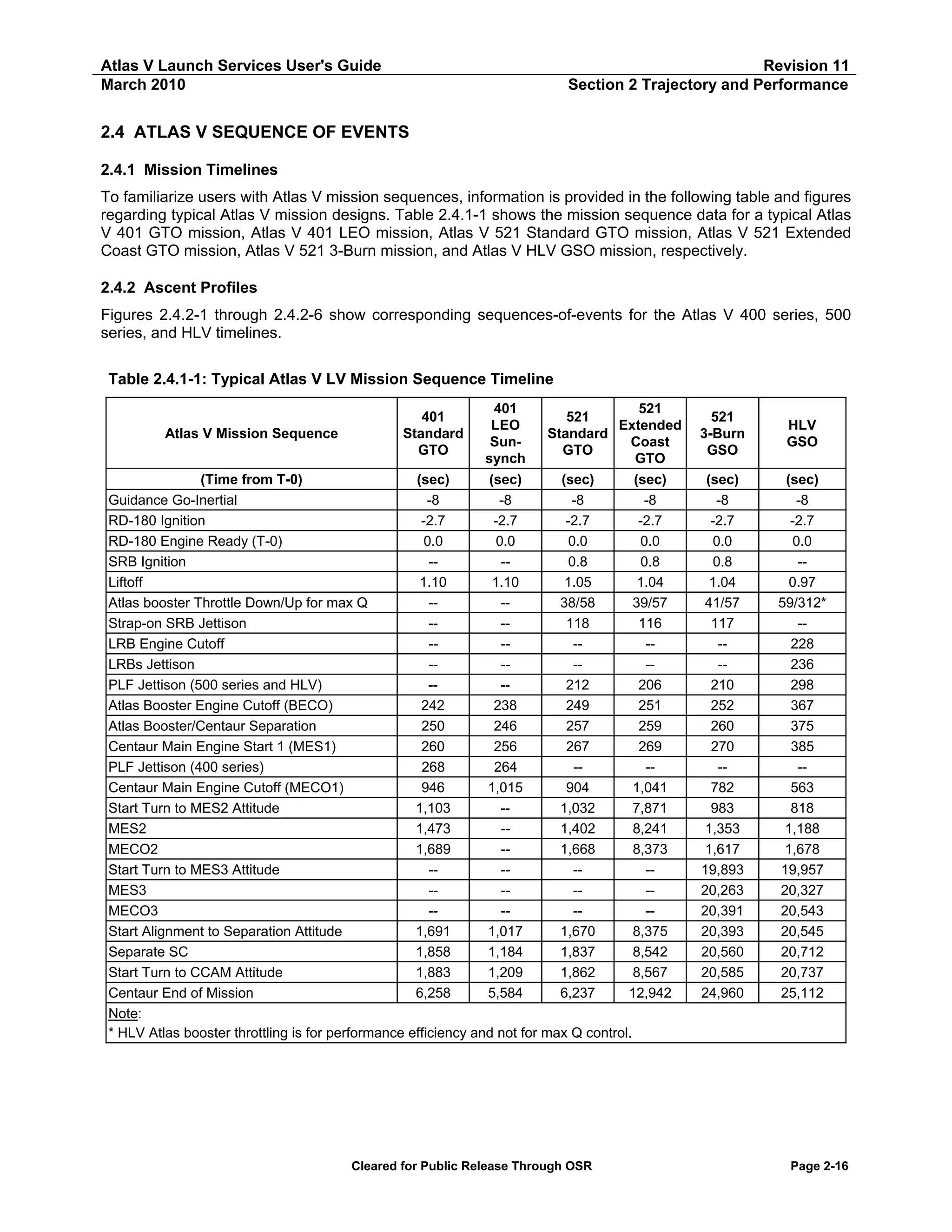
Section 2 Trajectory and Performance
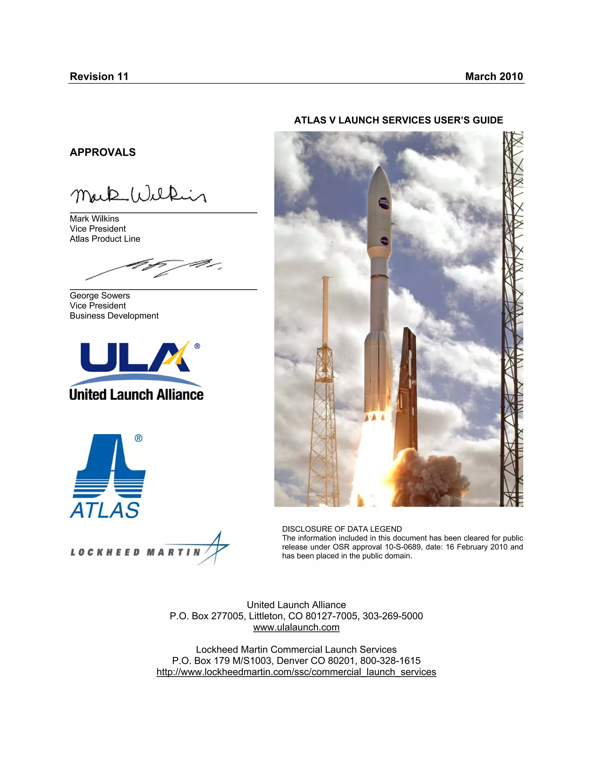
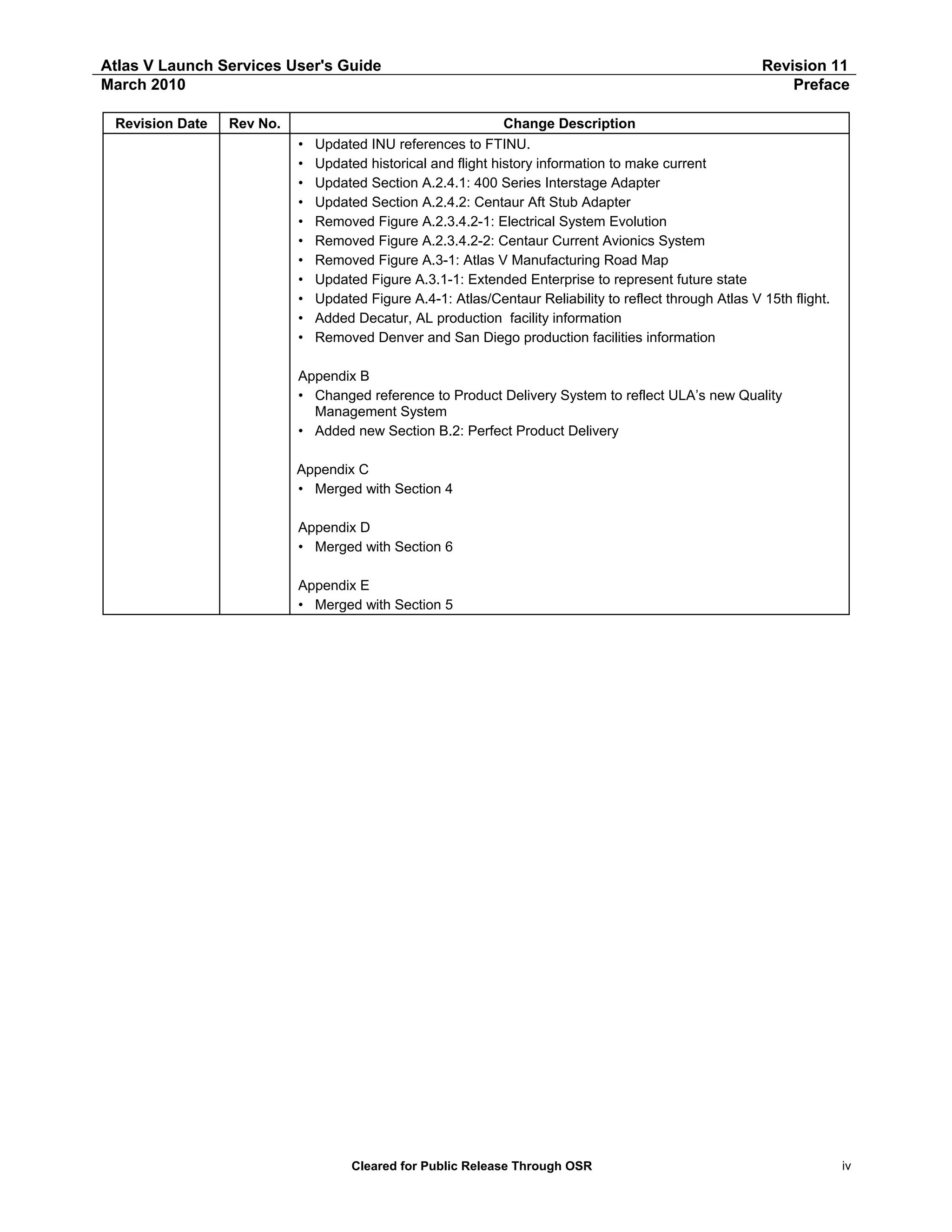
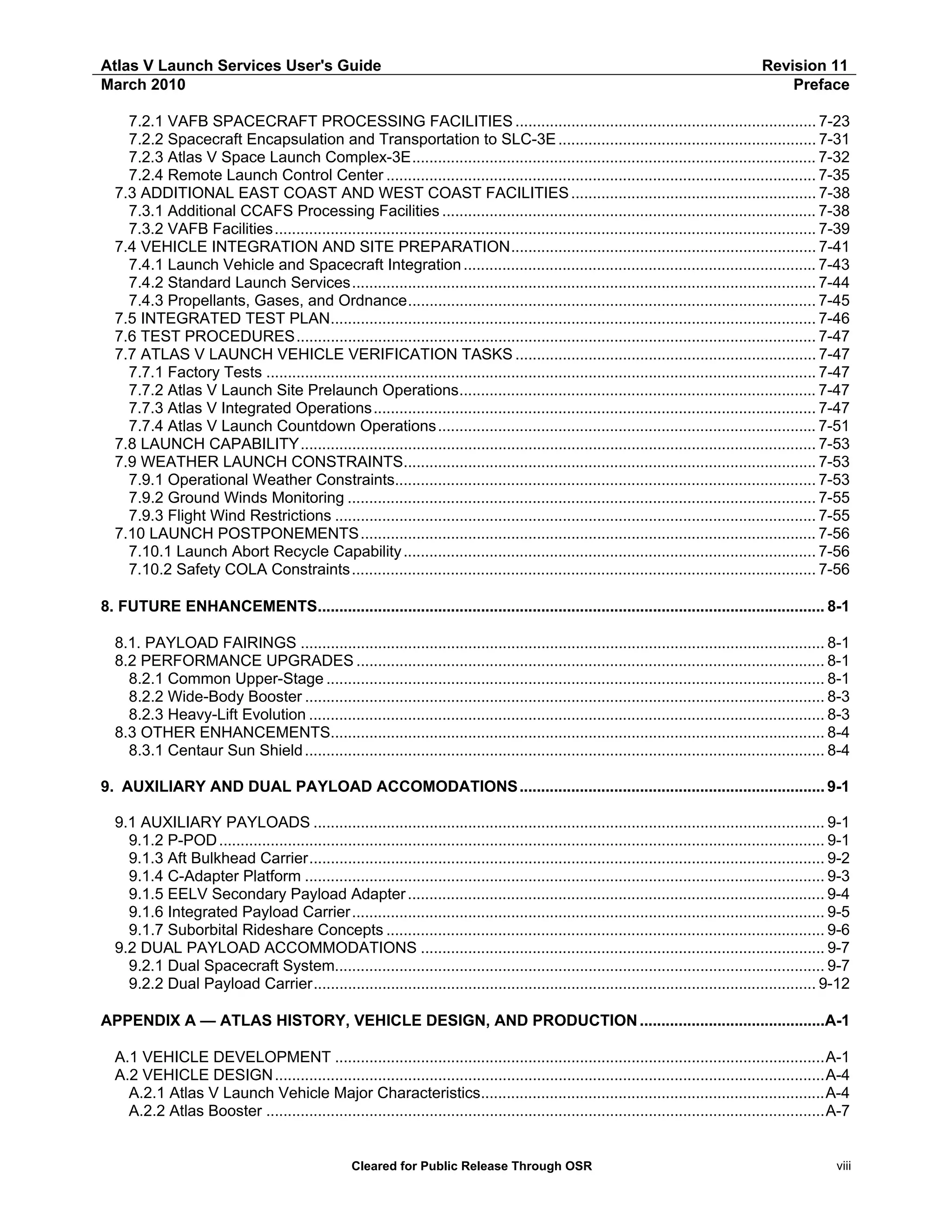
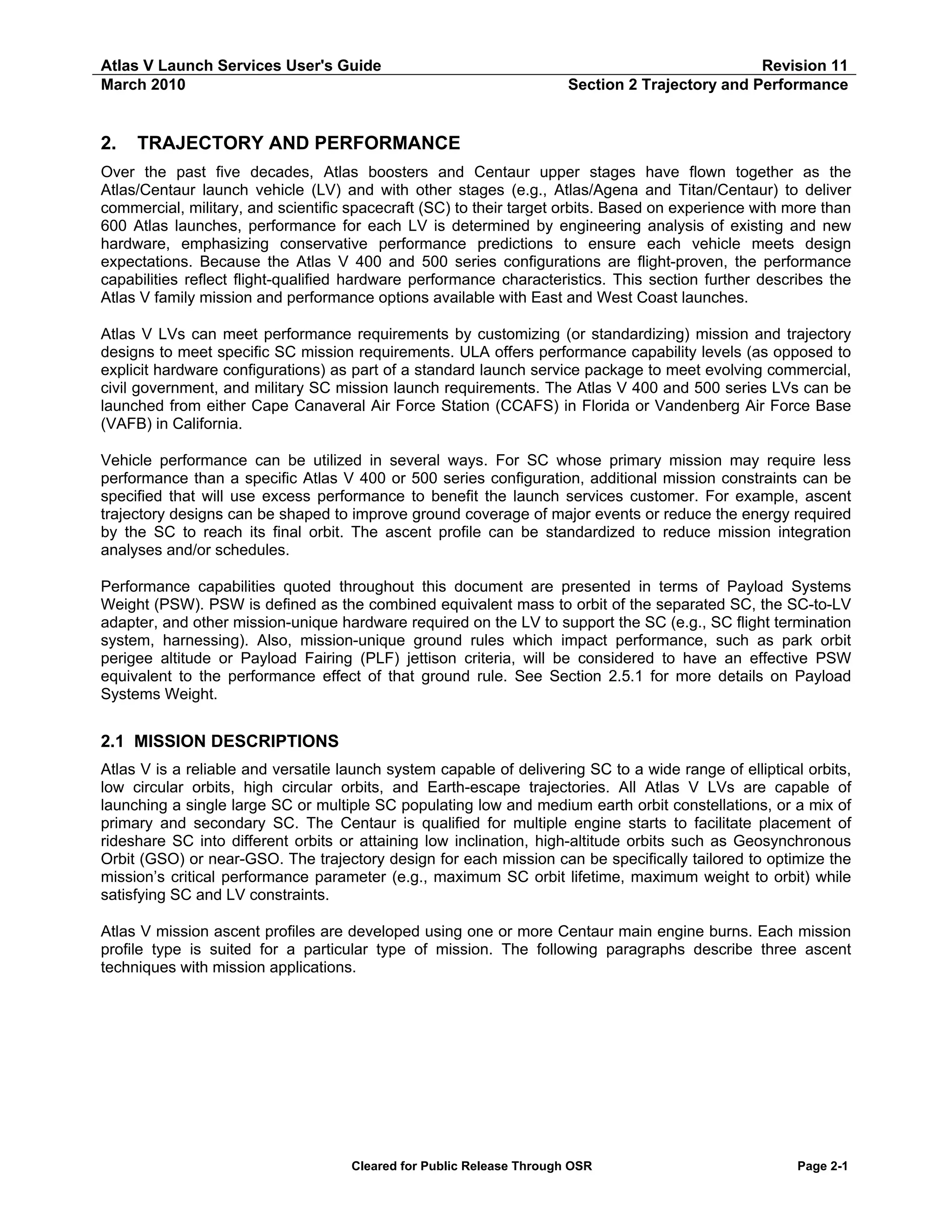
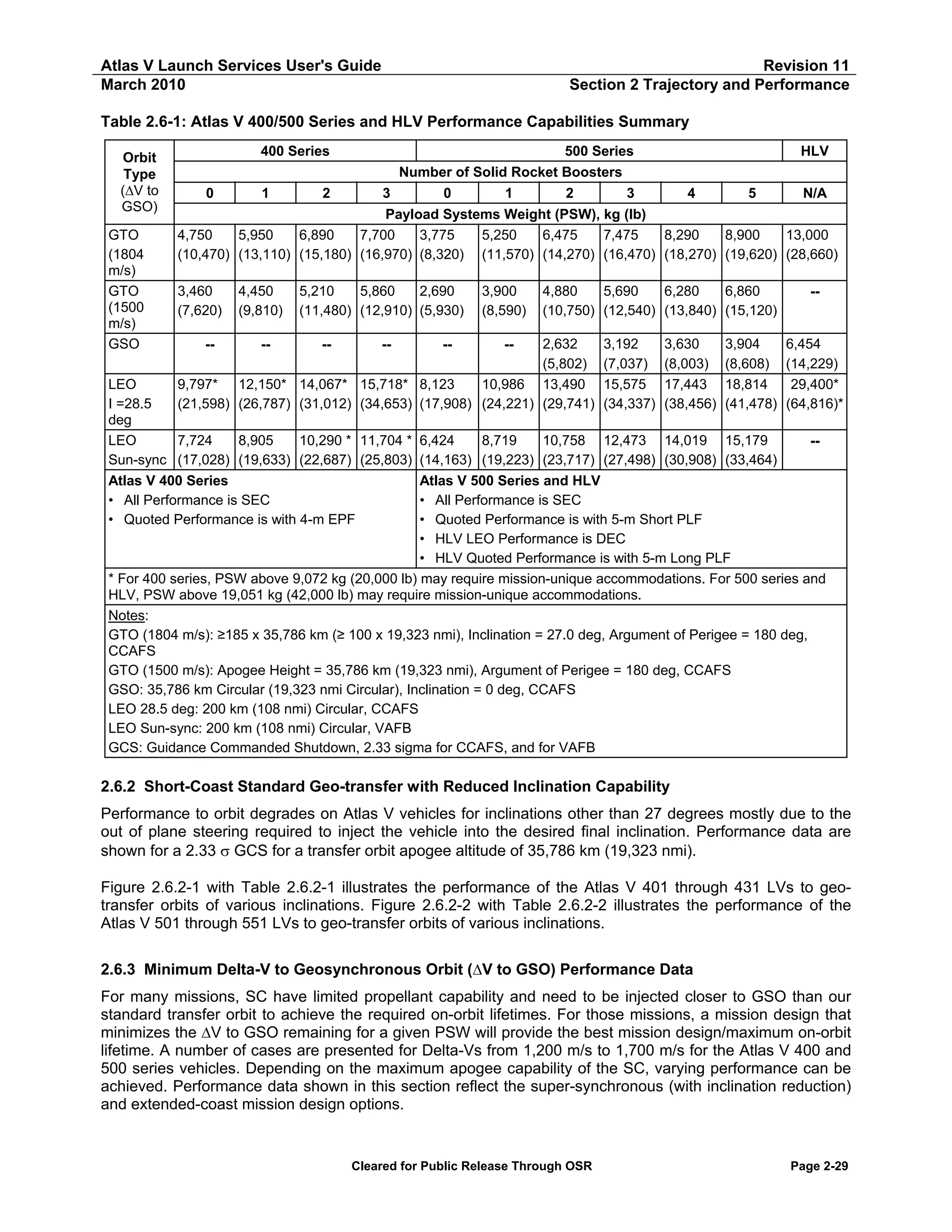
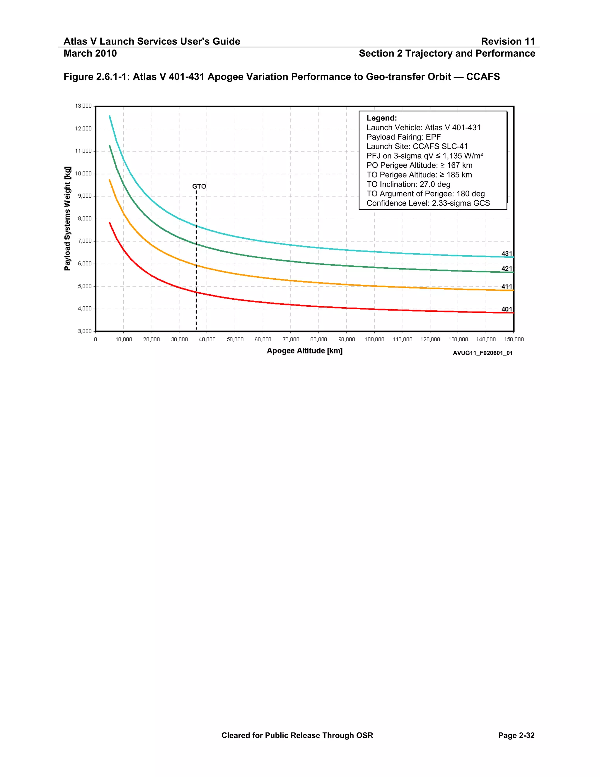
Table 2.6.1-1: Atlas V 401-431 Geo-transfer Orbit Performance — PSW vs Apogee Altitude (1 of 2)
Atlas V 401 GTO — PSW vs Apogee Altitude
Apogee Altitude
Payload Systems Weight
[km]
[nmi]
[kg]
[lb]
5,000
2,700
7,827
17,256
7,500
4,050
7,135
15,731
10,000
5,400
6,625
14,607
12,500
6,749
6,238
13,753
15,000
8,099
5,933
13,080
17,500
9,449
5,688
12,540
20,000
10,799
5,487
12,096
22,500
12,149
5,318
11,725
25,000
13,499
5,176
11,411
27,500
14,849
5,054
11,142
30,000
16,199
4,948
10,909
35,000
18,898
4,774
10,524
35,786
19,323
4,750
10,470
40,000
21,598
4,636
10,221
45,000
24,298
4,525
9,976
50,000
26,998
4,433
9,773
55,000
29,698
4,356
9,603
60,000
32,397
4,290
9,458
65,000
35,097
4,234
9,334
70,000
37,797
4,184
9,225
75,000
40,497
4,141
9,130
80,000
43,197
4,103
9,046
85,000
45,896
4,069
8,970
90,000
48,596
4,038
8,903
95,000
51,296
4,011
8,842
100,000
53,996
3,986
8,787
105,000
56,695
3,963
8,737
110,000
59,395
3,942
8,691
115,000
62,095
3,923
8,649
120,000
64,795
3,905
8,610
125,000
67,495
3,889
8,574
130,000
70,194
3,874
8,540
135,000
72,894
3,860
8,510
140,000
75,594
3,847
8,481
145,000
78,294
3,835
8,454
150,000
80,994
3,823
8,428
Notes:
Launch Site: CCAFS SLC-41
PLF Jettison at 3-sigma qV ≤ 1,135 W/m² (360 BTU/ft²-hr)
Park Orbit Perigee Altitude ≥ 167 km (90 nmi)
Transfer Orbit Perigee Altitude ≥ 185 km (100 nmi)
Transfer Orbit Inclination = 27.0 deg
Argument of Perigee = 180 deg
Confidence Level: 2.33 Sigma GCS
All parameters are at SC Separation except Apogee,
which is at 1st SC Apogee.
Only oblate Earth effects were taken into account when
propagating to 1st SC Apogee.
Atlas V 411 GTO — PSW vs Apogee Altitude
Apogee Altitude
Payload Systems Weight
[km]
[nmi]
[kg]
[lb]
5,000
2,700
9,729
21,448
7,500
4,050
8,869
19,552
10,000
5,400
8,242
18,170
12,500
6,749
7,766
17,121
15,000
8,099
7,394
16,301
17,500
9,449
7,095
15,642
20,000
10,799
6,847
15,096
22,500
12,149
6,642
14,644
25,000
13,499
6,468
14,260
27,500
14,849
6,321
13,935
30,000
16,199
6,191
13,649
35,000
18,898
5,978
13,180
35,786
19,323
5,950
13,110
40,000
21,598
5,810
12,809
45,000
24,298
5,674
12,509
50,000
26,998
5,562
12,261
55,000
29,698
5,467
12,054
60,000
32,397
5,387
11,877
65,000
35,097
5,318
11,724
70,000
37,797
5,258
11,592
75,000
40,497
5,205
11,475
80,000
43,197
5,158
11,372
85,000
45,896
5,117
11,280
90,000
48,596
5,079
11,198
95,000
51,296
5,046
11,124
100,000
53,996
5,015
11,056
105,000
56,695
4,987
10,995
110,000
59,395
4,962
10,939
115,000
62,095
4,939
10,888
120,000
64,795
4,917
10,840
125,000
67,495
4,897
10,796
130,000
70,194
4,879
10,756
135,000
72,894
4,862
10,718
140,000
75,594
4,846
10,683
145,000
78,294
4,831
10,650
150,000
80,994
4,817
10,619
Notes:
Launch Site: CCAFS SLC-41
PLF Jettison at 3-sigma qV ≤ 1,135 W/m² (360 BTU/ft²-hr)
Park Orbit Perigee Altitude ≥ 167 km (90 nmi)
Transfer Orbit Perigee Altitude ≥ 185 km (100 nmi)
Transfer Orbit Inclination = 27.0 deg
Argument of Perigee = 180 deg
Confidence Level: 2.33 Sigma GCS
All parameters are at SC Separation except Apogee,
which is at 1st SC Apogee.
Only oblate Earth effects were taken into account when
propagating to 1st SC Apogee.
Cleared for Public Release Through OSR
Page 2-33](https://image.slidesharecdn.com/atlasvusersguide2010-140220084057-phpapp02/75/Atlas-v-usersguide2010-63-2048.jpg)
![Atlas V Launch Services User's Guide
March 2010
Revision 11
Section 2 Trajectory and Performance
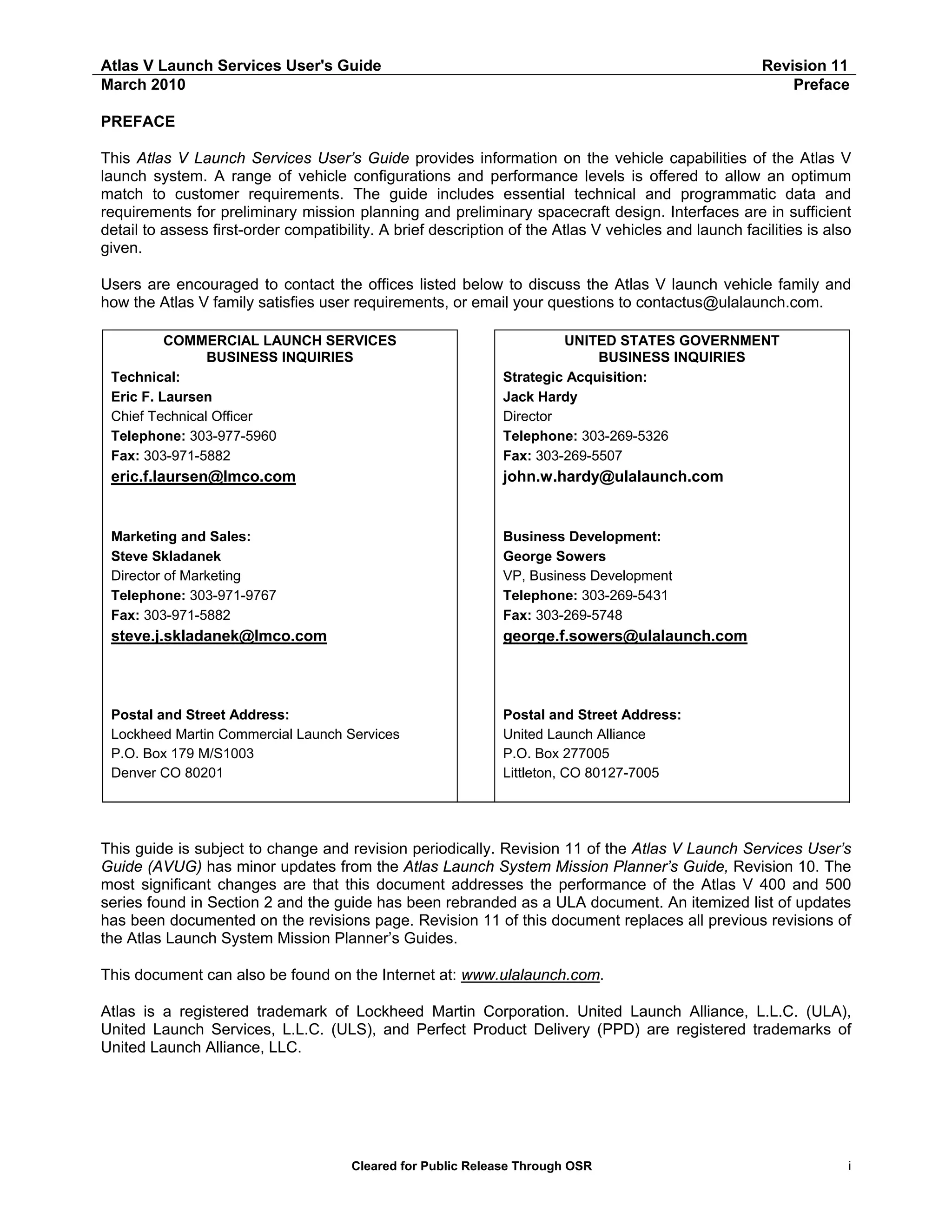
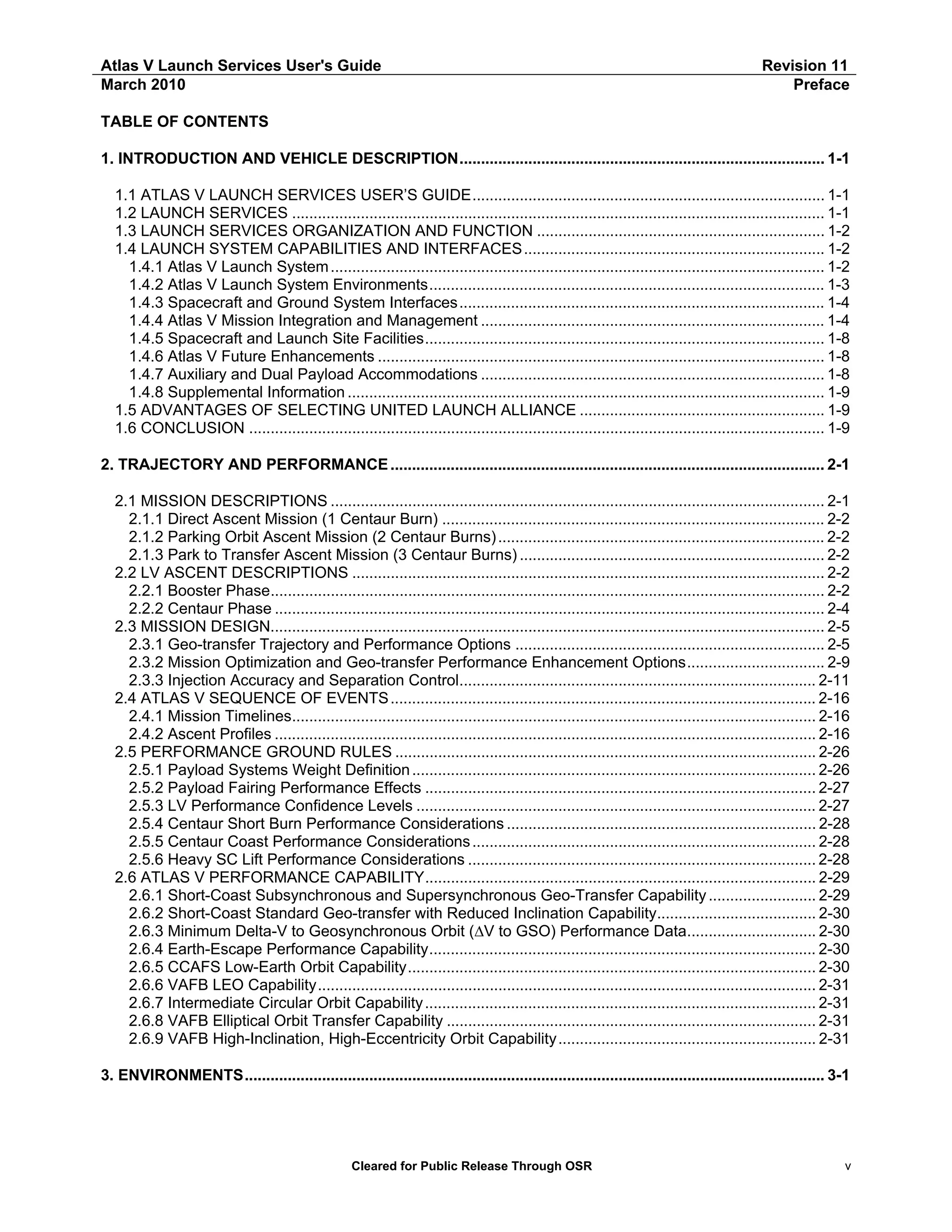
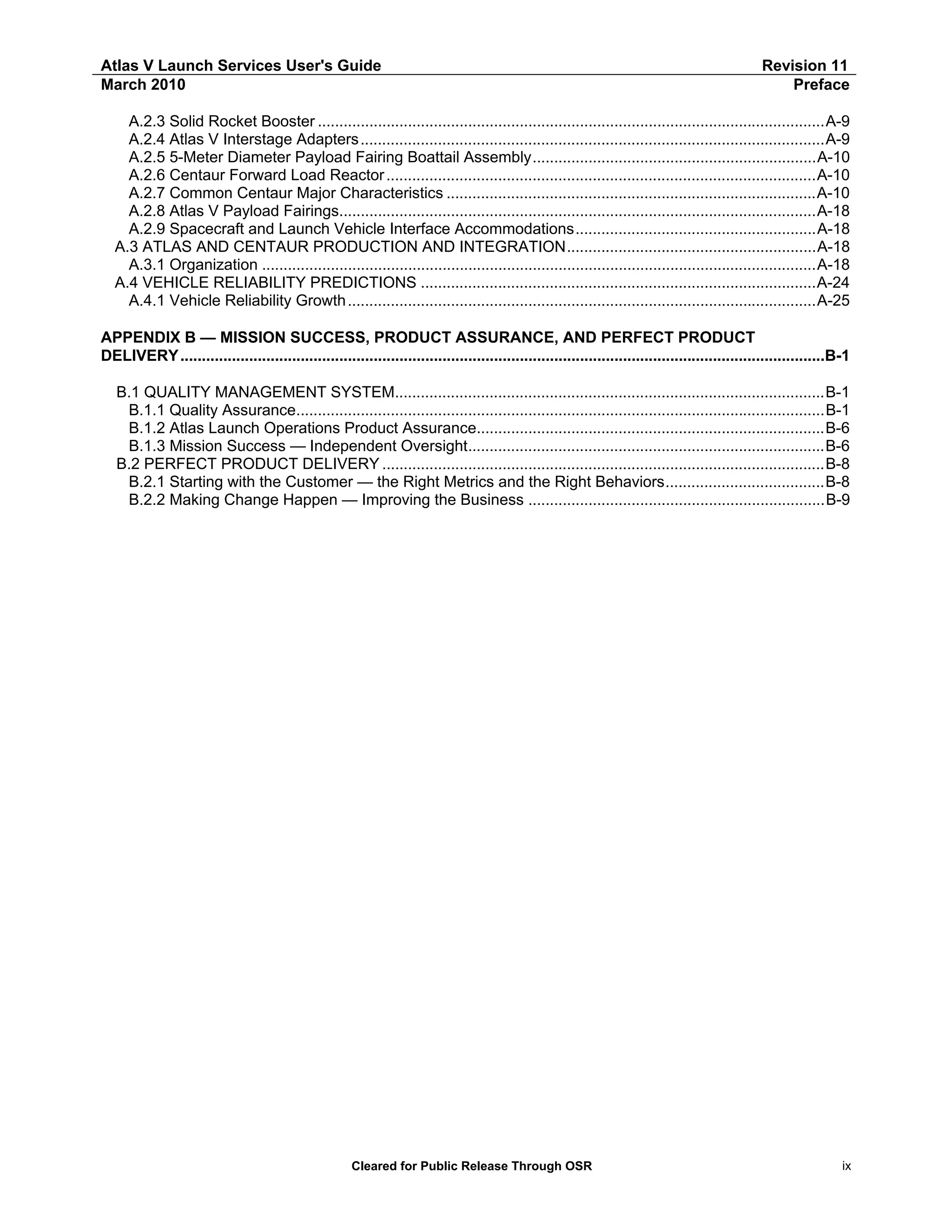
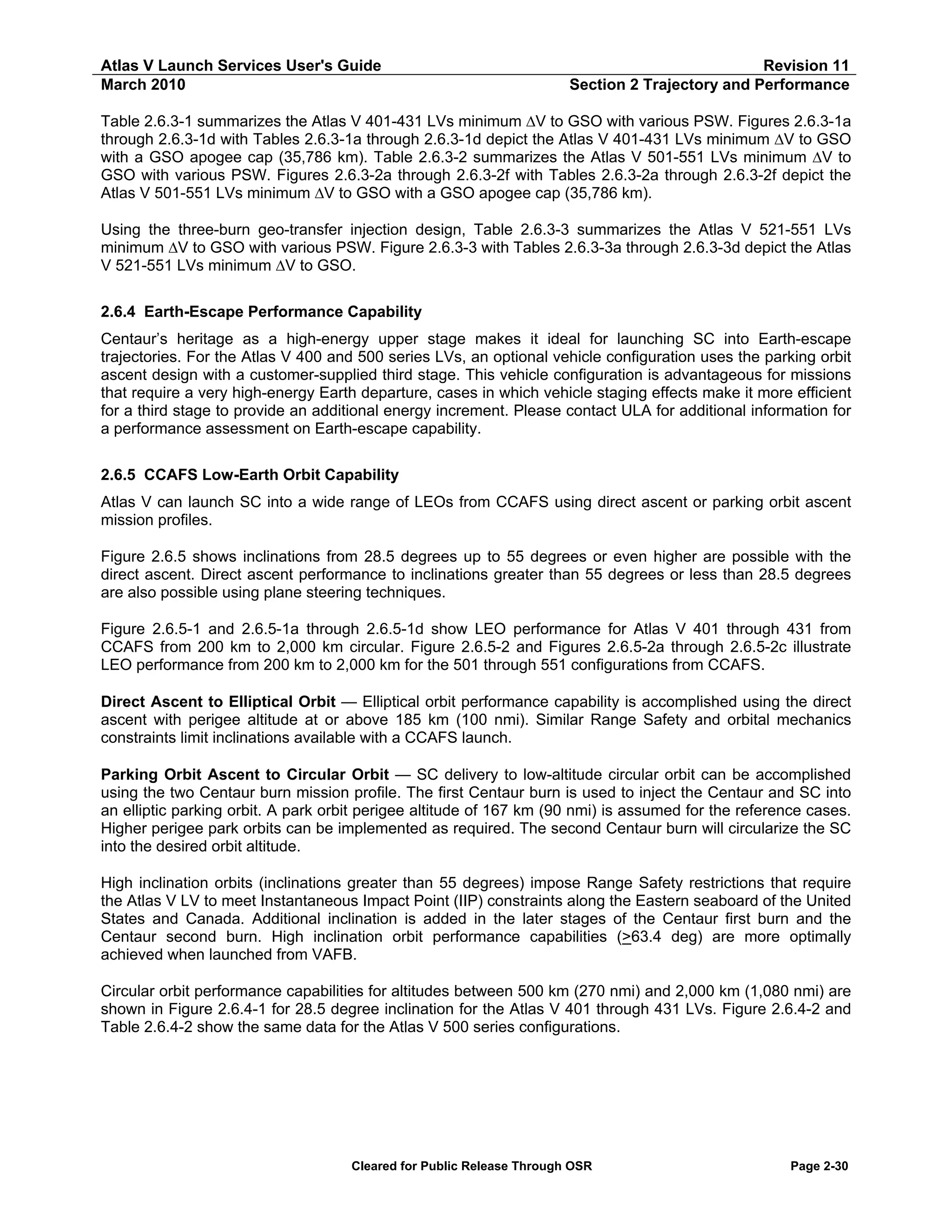
Table 2.6.1-1: Atlas V 401-431 Geo-transfer Orbit Performance — PSW vs Apogee Altitude (2 of 2)
Atlas V 421 GTO — PSW vs Apogee Altitude
Apogee Altitude
Payload Systems Weight
[km]
[nmi]
[kg]
[lb]
5,000
2,700
11,263
24,832
7,500
4,050
10,260
22,619
10,000
5,400
9,529
21,009
12,500
6,749
8,977
19,792
15,000
8,099
8,545
18,838
17,500
9,449
8,199
18,075
20,000
10,799
7,915
17,450
22,500
12,149
7,680
16,932
25,000
13,499
7,481
16,493
27,500
14,849
7,311
16,118
30,000
16,199
7,164
15,794
35,000
18,898
6,922
15,261
35,786
19,323
6,890
15,180
40,000
21,598
6,732
14,842
45,000
24,298
6,579
14,503
50,000
26,998
6,452
14,224
55,000
29,698
6,348
13,996
60,000
32,397
6,258
13,797
65,000
35,097
6,181
13,626
70,000
37,797
6,113
13,477
75,000
40,497
6,054
13,346
80,000
43,197
6,001
13,231
85,000
45,896
5,955
13,128
90,000
48,596
5,913
13,036
95,000
51,296
5,875
12,952
100,000
53,996
5,841
12,877
105,000
56,695
5,810
12,808
110,000
59,395
5,781
12,745
115,000
62,095
5,755
12,688
120,000
64,795
5,731
12,635
125,000
67,495
5,709
12,586
130,000
70,194
5,688
12,540
135,000
72,894
5,669
12,498
140,000
75,594
5,651
12,459
145,000
78,294
5,634
12,422
150,000
80,994
5,619
12,387
Notes:
Launch Site: CCAFS SLC-41
PLF Jettison at 3-sigma qV ≤ 1,135 W/m² (360 BTU/ft²-hr)
Park Orbit Perigee Altitude ≥ 167 km (90 nmi)
Transfer Orbit Perigee Altitude ≥ 185 km (100 nmi)
Transfer Orbit Inclination = 27.0 deg
Argument of Perigee = 180 deg
Confidence Level: 2.33 Sigma GCS
All parameters are at SC Separation except Apogee,
which is at 1st SC Apogee.
Only oblate Earth effects were taken into account when
propagating to 1st SC Apogee.
Atlas V 431 GTO — PSW vs Apogee Altitude
Apogee Altitude
Payload Systems Weight
[km]
[nmi]
[kg]
[lb]
5,000
2,700
12,573
27,719
7,500
4,050
11,453
25,250
10,000
5,400
10,637
23,451
12,500
6,749
10,021
22,093
15,000
8,099
9,541
21,033
17,500
9,449
9,156
20,186
20,000
10,799
8,841
19,492
22,500
12,149
8,579
18,914
25,000
13,499
8,358
18,426
27,500
14,849
8,169
18,009
30,000
16,199
8,005
17,648
35,000
18,898
7,736
17,056
35,786
19,323
7,700
16,970
40,000
21,598
7,525
16,591
45,000
24,298
7,355
16,215
50,000
26,998
7,215
15,906
55,000
29,698
7,097
15,647
60,000
32,397
6,997
15,427
65,000
35,097
6,912
15,237
70,000
37,797
6,837
15,073
75,000
40,497
6,771
14,928
80,000
43,197
6,713
14,800
85,000
45,896
6,662
14,686
90,000
48,596
6,615
14,584
95,000
51,296
6,573
14,492
100,000
53,996
6,536
14,409
105,000
56,695
6,501
14,333
110,000
59,395
6,470
14,263
115,000
62,095
6,441
14,199
120,000
64,795
6,414
14,140
125,000
67,495
6,389
14,086
130,000
70,194
6,367
14,036
135,000
72,894
6,348
13,996
140,000
75,594
6,329
13,952
145,000
78,294
6,310
13,911
150,000
80,994
6,293
13,873
Notes:
Launch Site: CCAFS SLC-41
PLF Jettison at 3-sigma qV ≤ 1,135 W/m² (360 BTU/ft²-hr)
Park Orbit Perigee Altitude ≥ 167 km (90 nmi)
Transfer Orbit Perigee Altitude ≥ 185 km (100 nmi)
Transfer Orbit Inclination = 27.0 deg
Argument of Perigee = 180 deg
Confidence Level: 2.33 Sigma GCS
All parameters are at SC Separation except Apogee,
which is at 1st SC Apogee.
Only oblate Earth effects were taken into account when
propagating to 1st SC Apogee
Cleared for Public Release Through OSR
Page 2-34](https://image.slidesharecdn.com/atlasvusersguide2010-140220084057-phpapp02/75/Atlas-v-usersguide2010-64-2048.jpg)
![Atlas V Launch Services User's Guide
March 2010
Revision 11
Section 2 Trajectory and Performance
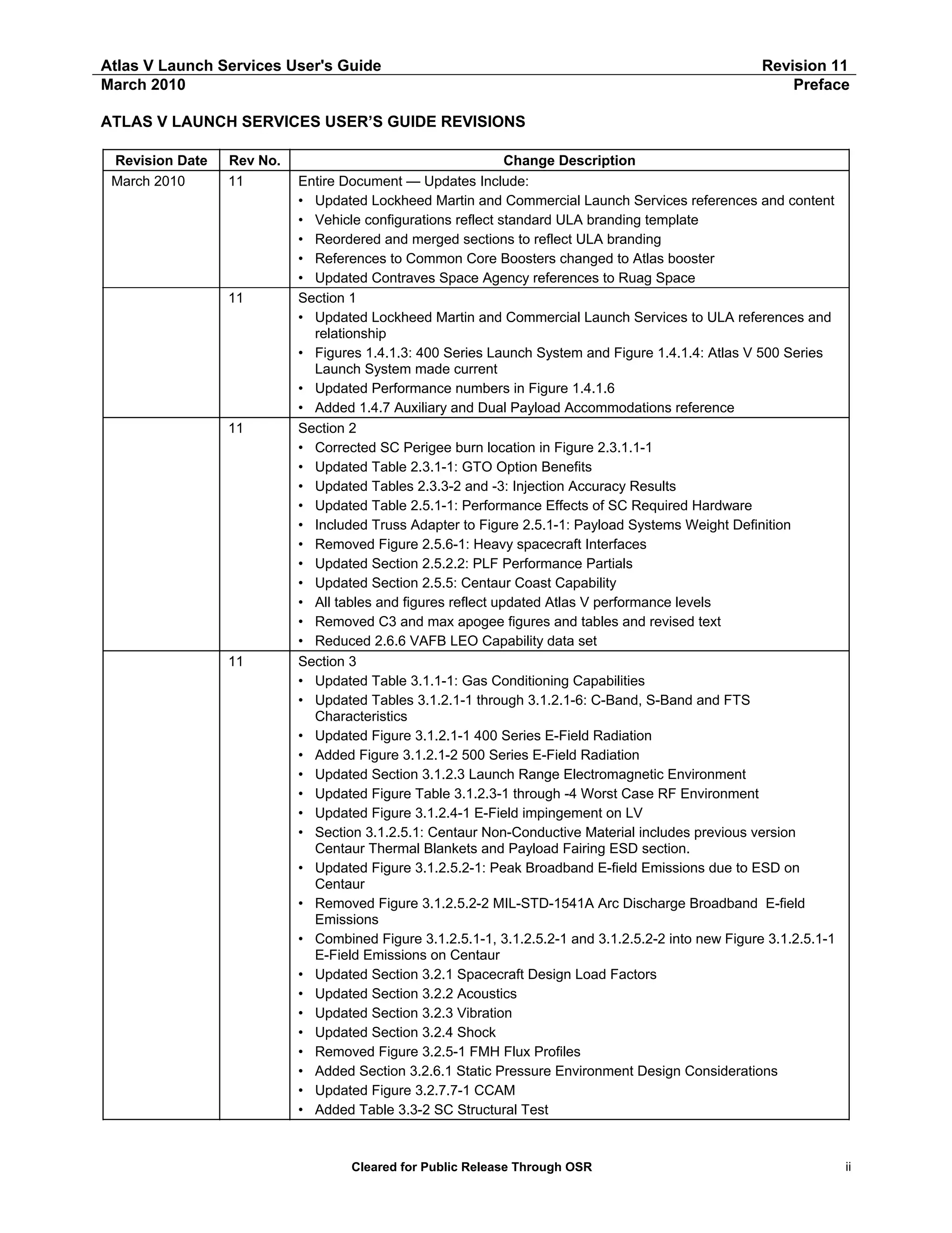
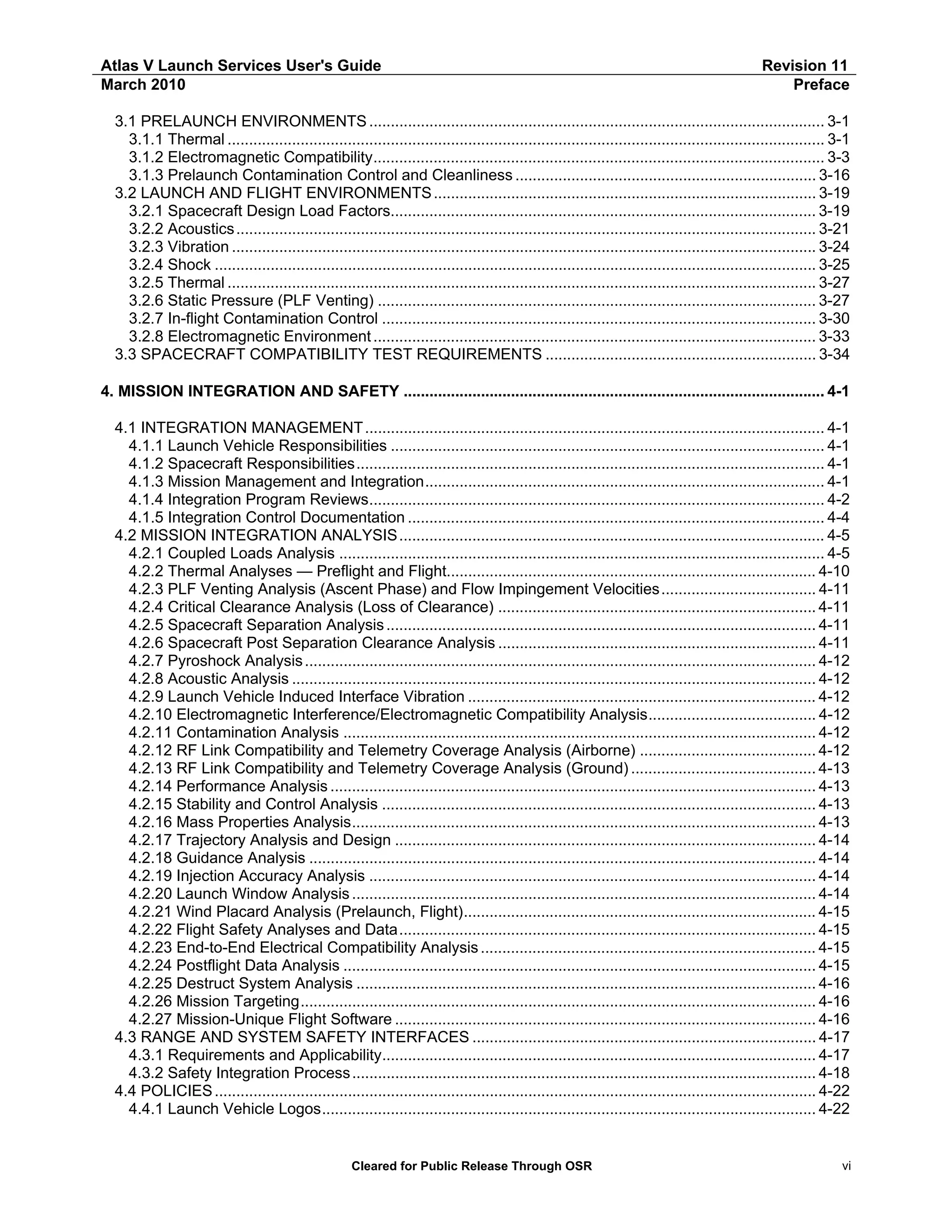
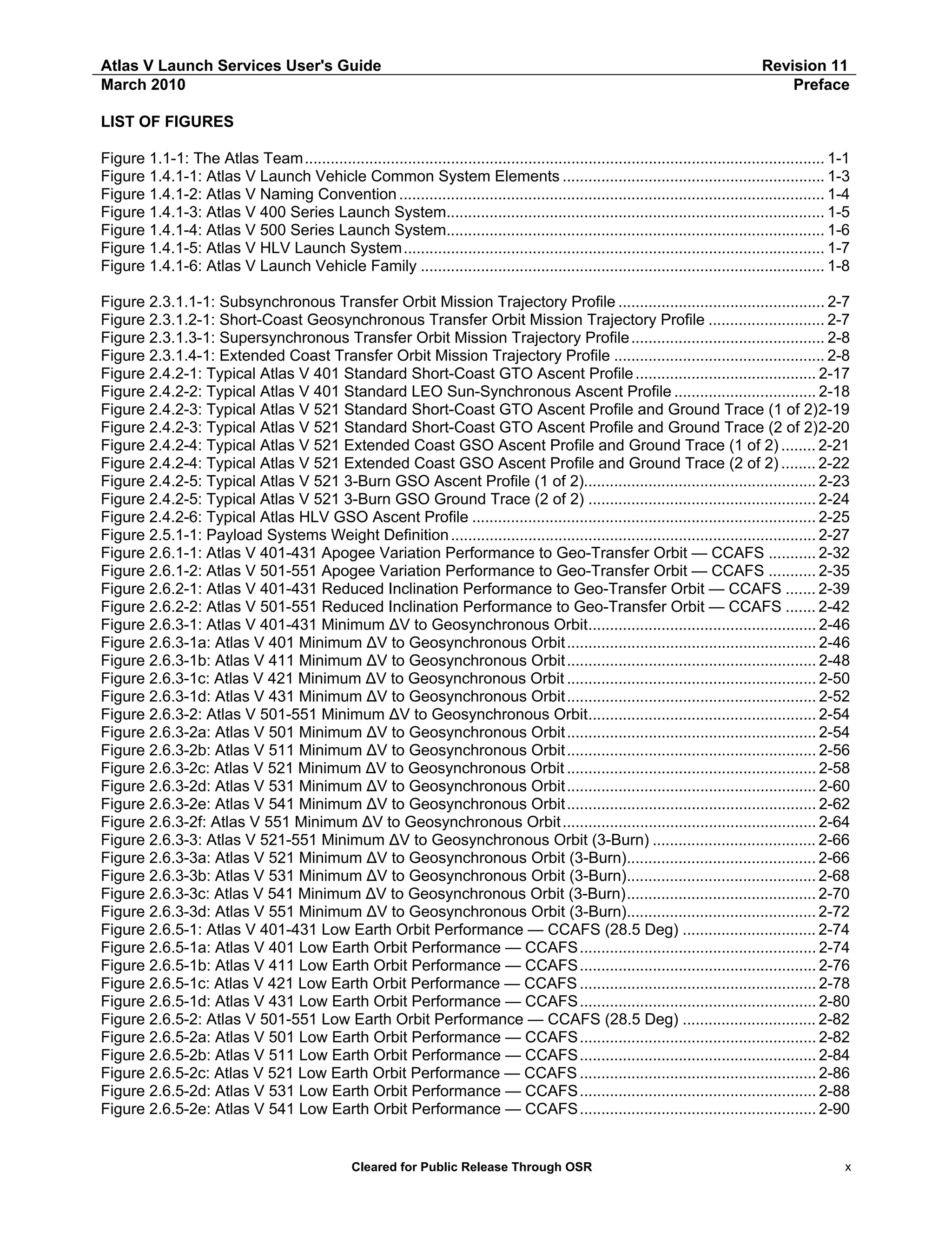
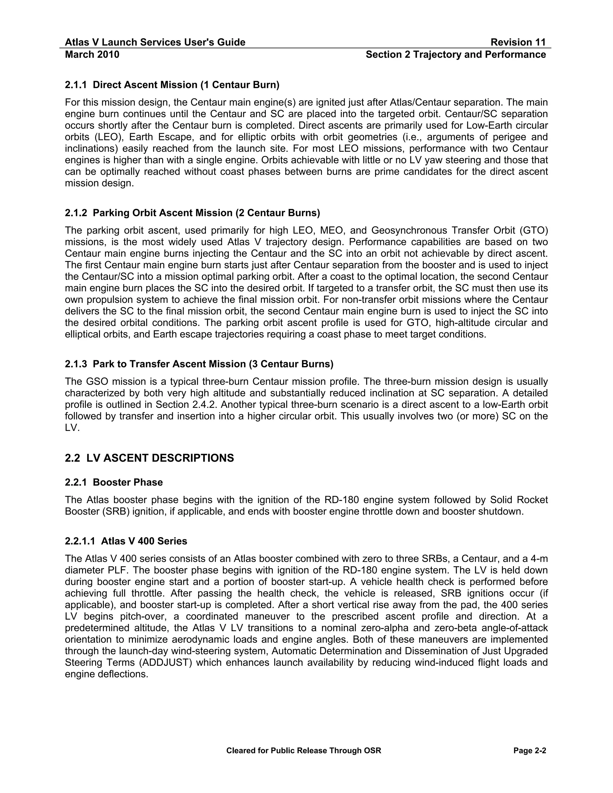
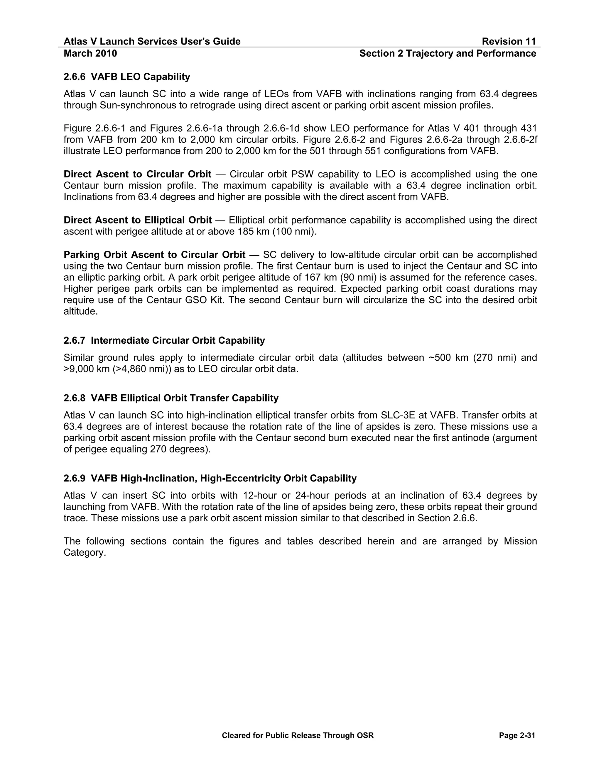
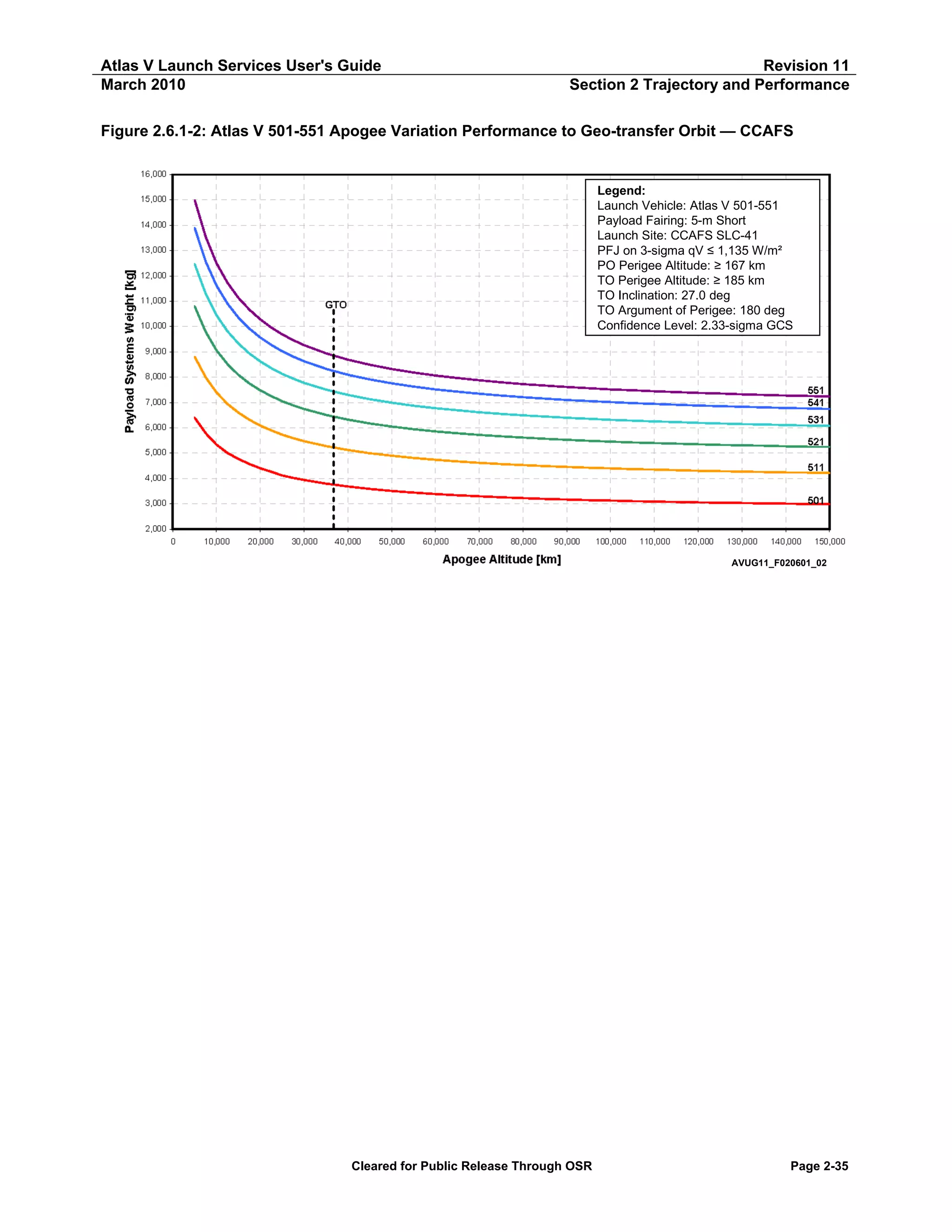
Table 2.6.1-2: Atlas V 501-551 Geo-transfer Orbit Performance — PSW vs Apogee Altitude (1 of 3)
Atlas V 501 GTO — PSW vs Apogee Altitude
Apogee Altitude
Payload Systems Weight
[km]
[nmi]
[kg]
[lb]
5,000
2,700
6,392
14,092
7,500
4,050
5,783
12,749
10,000
5,400
5,335
11,761
12,500
6,749
5,002
11,027
15,000
8,099
4,773
10,522
17,500
9,449
4,570
10,076
20,000
10,799
4,401
9,702
22,500
12,149
4,262
9,396
25,000
13,499
4,115
9,072
27,500
14,849
4,021
8,865
30,000
16,199
3,940
8,686
35,000
18,898
3,796
8,369
35,786
19,323
3,775
8,320
40,000
21,598
3,682
8,118
45,000
24,298
3,583
7,899
50,000
26,998
3,506
7,729
55,000
29,698
3,442
7,589
60,000
32,397
3,382
7,457
65,000
35,097
3,337
7,357
70,000
37,797
3,295
7,264
75,000
40,497
3,253
7,172
80,000
43,197
3,223
7,105
85,000
45,896
3,195
7,044
90,000
48,596
3,168
6,985
95,000
51,296
3,145
6,933
100,000
53,996
3,123
6,885
105,000
56,695
3,104
6,842
110,000
59,395
3,085
6,802
115,000
62,095
3,069
6,765
120,000
64,795
3,054
6,733
125,000
67,495
3,040
6,702
130,000
70,194
3,027
6,673
135,000
72,894
3,014
6,644
140,000
75,594
3,003
6,619
145,000
78,294
2,992
6,596
150,000
80,994
2,982
6,574
Notes:
Launch Site: CCAFS SLC-41
PLF Jettison at 3-sigma qV ≤ 1,135 W/m² (360 BTU/ft²-hr)
Park Orbit Perigee Altitude ≥ 167 km (90 nmi)
Transfer Orbit Perigee Altitude ≥ 185 km (100 nmi)
Transfer Orbit Inclination = 27.0 deg
Argument of Perigee = 180 deg
Confidence Level: 2.33 Sigma GCS
All parameters are at SC Separation except Apogee,
which is at 1st SC Apogee.
Only oblate Earth effects were taken into account when
st
propagating to 1 SC Apogee.
Atlas V 511 GTO — PSW vs Apogee Altitude
Apogee Altitude
Payload Systems Weight
[km]
[nmi]
[kg]
[lb]
5,000
2,700
8,807
19,416
7,500
4,050
7,988
17,611
10,000
5,400
7,394
16,301
12,500
6,749
6,944
15,310
15,000
8,099
6,594
14,536
17,500
9,449
6,313
13,918
20,000
10,799
6,083
13,411
22,500
12,149
5,893
12,991
25,000
13,499
5,731
12,635
27,500
14,849
5,593
12,331
30,000
16,199
5,473
12,066
35,000
18,898
5,277
11,634
35,786
19,323
5,250
11,570
40,000
21,598
5,123
11,294
45,000
24,298
4,998
11,018
50,000
26,998
4,895
10,791
55,000
29,698
4,809
10,601
60,000
32,397
4,735
10,439
65,000
35,097
4,672
10,300
70,000
37,797
4,617
10,179
75,000
40,497
4,569
10,072
80,000
43,197
4,526
9,978
85,000
45,896
4,488
9,894
90,000
48,596
4,454
9,819
95,000
51,296
4,423
9,752
100,000
53,996
4,395
9,690
105,000
56,695
4,370
9,634
110,000
59,395
4,347
9,583
115,000
62,095
4,326
9,536
120,000
64,795
4,306
9,493
125,000
67,495
4,288
9,453
130,000
70,194
4,271
9,416
135,000
72,894
4,255
9,382
140,000
75,594
4,241
9,350
145,000
78,294
4,227
9,320
150,000
80,994
4,215
9,292
Notes:
Launch Site: CCAFS SLC-41
PLF Jettison at 3-sigma qV ≤ 1,135 W/m² (360 BTU/ft²-hr)
Park Orbit Perigee Altitude ≥ 167 km (90 nmi)
Transfer Orbit Perigee Altitude ≥ 185 km (100 nmi)
Transfer Orbit Inclination = 27.0 deg
Argument of Perigee = 180 deg
Confidence Level: 2.33 Sigma GCS
All parameters are at SC Separation except Apogee,
which is at 1st SC Apogee.
Only oblate Earth effects were taken into account when
propagating to 1st SC Apogee
Cleared for Public Release Through OSR
Page 2-36](https://image.slidesharecdn.com/atlasvusersguide2010-140220084057-phpapp02/75/Atlas-v-usersguide2010-66-2048.jpg)
![Atlas V Launch Services User's Guide
March 2010
Revision 11
Section 2 Trajectory and Performance
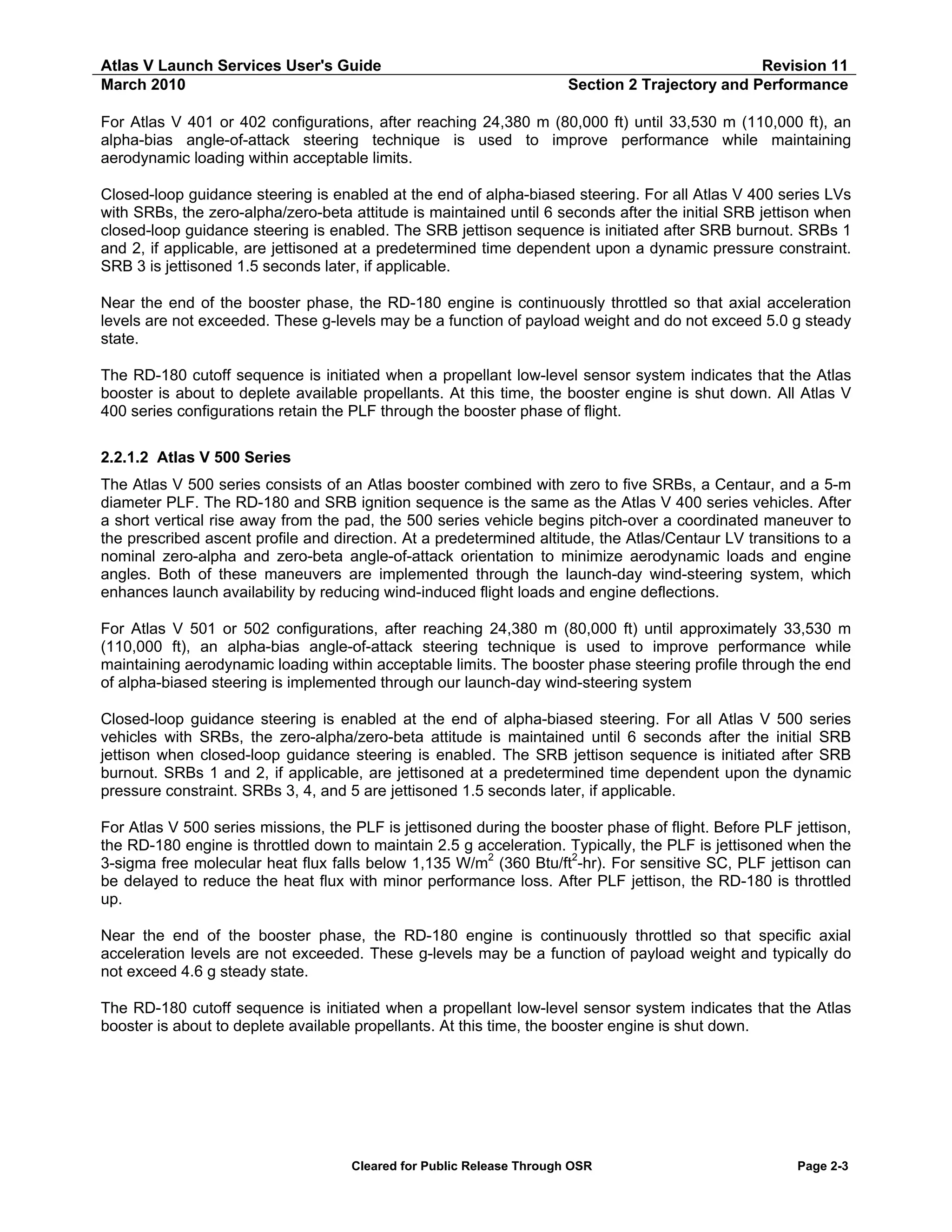
Table 2.6.1-2: Atlas V 501-551 Geo-transfer Orbit Performance — PSW vs Apogee Altitude (2 of 3)
Atlas V 521 GTO — PSW vs Apogee Altitude
Apogee Altitude
Payload Systems Weight
[km]
[nmi]
[kg]
[lb]
5,000
2,700
10,790
23,789
7,500
4,050
9,785
21,571
10,000
5,400
9,058
19,970
12,500
6,749
8,512
18,766
15,000
8,099
8,088
17,830
17,500
9,449
7,749
17,083
20,000
10,799
7,475
16,480
22,500
12,149
7,245
15,973
25,000
13,499
7,051
15,545
27,500
14,849
6,885
15,180
30,000
16,199
6,742
14,863
35,000
18,898
6,507
14,345
35,786
19,323
6,475
14,270
40,000
21,598
6,322
13,938
45,000
24,298
6,173
13,609
50,000
26,998
6,050
13,338
55,000
29,698
5,947
13,111
60,000
32,397
5,860
12,918
65,000
35,097
5,784
12,752
70,000
37,797
5,719
12,608
75,000
40,497
5,662
12,482
80,000
43,197
5,611
12,370
85,000
45,896
5,566
12,270
90,000
48,596
5,525
12,180
95,000
51,296
5,489
12,100
100,000
53,996
5,456
12,027
105,000
56,695
5,425
11,961
110,000
59,395
5,398
11,900
115,000
62,095
5,373
11,844
120,000
64,795
5,349
11,793
125,000
67,495
5,328
11,746
130,000
70,194
5,308
11,702
135,000
72,894
5,289
11,661
140,000
75,594
5,272
11,623
145,000
78,294
5,256
11,587
150,000
80,994
5,241
11,554
Notes:
Launch Site: CCAFS SLC-41
PLF Jettison at 3-sigma qV ≤ 1,135 W/m² (360 BTU/ft²-hr)
Park Orbit Perigee Altitude ≥ 167 km (90 nmi)
Transfer Orbit Perigee Altitude ≥ 185 km (100 nmi)
Transfer Orbit Inclination = 27.0 deg
Argument of Perigee = 180 deg
Confidence Level: 2.33 Sigma GCS
All parameters are at SC Separation except Apogee,
which is at 1st SC Apogee.
Only oblate Earth effects were taken into account when
propagating to 1st SC Apogee.
Atlas V 531 GTO — PSW vs Apogee Altitude
Apogee Altitude
Payload Systems Weight
[km]
[nmi]
[kg]
[lb]
5,000
2,700
12,455
27,458
7,500
4,050
11,288
24,885
10,000
5,400
10,446
23,029
12,500
6,749
9,806
21,619
15,000
8,099
9,323
20,554
17,500
9,449
8,933
19,694
20,000
10,799
8,614
18,990
22,500
12,149
8,350
18,409
25,000
13,499
8,129
17,922
27,500
14,849
7,940
17,505
30,000
16,199
7,776
17,143
35,000
18,898
7,508
16,552
35,786
19,323
7,475
16,470
40,000
21,598
7,301
16,095
45,000
24,298
7,131
15,722
50,000
26,998
6,991
15,414
55,000
29,698
6,875
15,156
60,000
32,397
6,775
14,937
65,000
35,097
6,690
14,749
70,000
37,797
6,616
14,585
75,000
40,497
6,551
14,442
80,000
43,197
6,493
14,315
85,000
45,896
6,442
14,202
90,000
48,596
6,396
14,100
95,000
51,296
6,354
14,009
100,000
53,996
6,317
13,926
105,000
56,695
6,283
13,851
110,000
59,395
6,252
13,782
115,000
62,095
6,223
13,719
120,000
64,795
6,197
13,661
125,000
67,495
6,172
13,607
130,000
70,194
6,150
13,558
135,000
72,894
6,129
13,512
140,000
75,594
6,109
13,469
145,000
78,294
6,091
13,428
150,000
80,994
6,074
13,390
Notes:
Launch Site: CCAFS SLC-41
PLF Jettison at 3-sigma qV ≤ 1,135 W/m² (360 BTU/ft²-hr)
Park Orbit Perigee Altitude ≥ 167 km (90 nmi)
Transfer Orbit Perigee Altitude ≥ 185 km (100 nmi)
Transfer Orbit Inclination = 27.0 deg
Argument of Perigee = 180 deg
Confidence Level: 2.33 Sigma GCS
All parameters are at SC Separation except Apogee,
which is at 1st SC Apogee.
Only oblate Earth effects were taken into account when
propagating to 1st SC Apogee
Cleared for Public Release Through OSR
Page 2-37](https://image.slidesharecdn.com/atlasvusersguide2010-140220084057-phpapp02/75/Atlas-v-usersguide2010-67-2048.jpg)
![Atlas V Launch Services User's Guide
March 2010
Revision 11
Section 2 Trajectory and Performance
Table 2.6.1-2: Atlas V 501-551 Geo-transfer Orbit Performance — PSW vs Apogee Altitude (3 of 3)
Atlas V 541 GTO — PSW vs Apogee Altitude
Apogee Altitude
Payload Systems Weight
[km]
[nmi]
[kg]
[lb]
5,000
2,700
13,885
30,611
7,500
4,050
12,561
27,692
10,000
5,400
11,610
25,596
12,500
6,749
10,901
24,032
15,000
8,099
10,345
22,807
17,500
9,449
9,913
21,854
20,000
10,799
9,562
21,080
22,500
12,149
9,268
20,432
25,000
13,499
9,021
19,888
27,500
14,849
8,810
19,424
30,000
16,199
8,627
19,020
35,000
18,898
8,330
18,365
35,786
19,323
8,290
18,270
40,000
21,598
8,096
17,850
45,000
24,298
7,909
17,435
50,000
26,998
7,754
17,094
55,000
29,698
7,624
16,809
60,000
32,397
7,514
16,566
65,000
35,097
7,424
16,367
70,000
37,797
7,342
16,186
75,000
40,497
7,270
16,027
80,000
43,197
7,206
15,887
85,000
45,896
7,150
15,762
90,000
48,596
7,099
15,650
95,000
51,296
7,053
15,550
100,000
53,996
7,012
15,458
105,000
56,695
6,974
15,376
110,000
59,395
6,940
15,300
115,000
62,095
6,908
15,230
120,000
64,795
6,879
15,166
125,000
67,495
6,852
15,107
130,000
70,194
6,827
15,052
135,000
72,894
6,804
15,001
140,000
75,594
6,783
14,953
145,000
78,294
6,763
14,909
150,000
80,994
6,744
14,868
Notes:
Launch Site: CCAFS SLC-41
PLF Jettison at 3-sigma qV ≤ 1,135 W/m² (360 BTU/ft²-hr)
Park Orbit Perigee Altitude ≥ 167 km (90 nmi)
Transfer Orbit Perigee Altitude ≥ 185 km (100 nmi)
Transfer Orbit Inclination = 27.0 deg
Argument of Perigee = 180 deg
Confidence Level: 2.33 Sigma GCS
All parameters are at SC Separation except Apogee,
which is at 1st SC Apogee.
Only oblate Earth effects were taken into account when
propagating to 1st SC Apogee.
Atlas V 551 GTO — PSW vs Apogee Altitude
Apogee Altitude
Payload Systems Weight
[km]
[nmi]
[kg]
[lb]
5,000
2,700
14,988
33,042
7,500
4,050
13,534
29,837
10,000
5,400
12,497
27,551
12,500
6,749
11,726
25,852
15,000
8,099
11,131
24,540
17,500
9,449
10,659
23,499
20,000
10,799
10,275
22,652
22,500
12,149
9,955
21,947
25,000
13,499
9,690
21,363
27,500
14,849
9,461
20,857
30,000
16,199
9,265
20,427
35,000
18,898
8,944
19,717
35,786
19,323
8,900
19,620
40,000
21,598
8,691
19,160
45,000
24,298
8,488
18,714
50,000
26,998
8,322
18,346
55,000
29,698
8,181
18,036
60,000
32,397
8,064
17,777
65,000
35,097
7,962
17,553
70,000
37,797
7,873
17,357
75,000
40,497
7,796
17,187
80,000
43,197
7,727
17,035
85,000
45,896
7,666
16,900
90,000
48,596
7,611
16,780
95,000
51,296
7,562
16,672
100,000
53,996
7,517
16,573
105,000
56,695
7,481
16,493
110,000
59,395
7,444
16,411
115,000
62,095
7,410
16,336
120,000
64,795
7,379
16,267
125,000
67,495
7,350
16,204
130,000
70,194
7,323
16,145
135,000
72,894
7,298
16,089
140,000
75,594
7,275
16,038
145,000
78,294
7,253
15,991
150,000
80,994
7,233
15,946
Notes:
Launch Site: CCAFS SLC-41
PLF Jettison at 3-sigma qV ≤ 1,135 W/m² (360 BTU/ft²-hr)
Park Orbit Perigee Altitude ≥ 167 km (90 nmi)
Transfer Orbit Perigee Altitude ≥ 185 km (100 nmi)
Transfer Orbit Inclination = 27.0 deg
Argument of Perigee = 180 deg
Confidence Level: 2.33 Sigma GCS
All parameters are at SC Separation except Apogee,
which is at 1st SC Apogee.
Only oblate Earth effects were taken into account when
propagating to 1st SC Apogee
Cleared for Public Release Through OSR
Page 2-38](https://image.slidesharecdn.com/atlasvusersguide2010-140220084057-phpapp02/75/Atlas-v-usersguide2010-68-2048.jpg)
![Atlas V Launch Services User's Guide
March 2010
Revision 11
Section 2 Trajectory and Performance
Figure 2.6.2-1: Atlas V 401-431 Reduced Inclination Performance to Geo-Transfer Orbit — CCAFS
Legend:
Launch Vehicle: Atlas V 401-431
Payload Fairing: EPF
Launch Site: CCAFS LC—41
PFJ on 3-sigma qV ≤ 1,135 W/m²
PO Perigee Altitude: ≥ 167 km
TO Perigee Altitude: ≥ 185 km
TO Apogee Altitude: 35,786 km
TO Argument of Perigee: 180 deg
Confidence Level: 2.33-sigma GCS
Transfer Orbit Inclination [degrees]
Cleared for Public Release Through OSR
AVUG11_F020602_01_b
Page 2-39](https://image.slidesharecdn.com/atlasvusersguide2010-140220084057-phpapp02/75/Atlas-v-usersguide2010-69-2048.jpg)
![Atlas V Launch Services User's Guide
March 2010
Revision 11
Section 2 Trajectory and Performance
Table 2.6.2-1: Atlas V 401-431 Geo-transfer Orbit Performance — PSW vs Orbit Inclination (1 of 2)
Atlas V 401 GTO — PSW vs Inclination
Inclination
Payload Systems Weight
[deg]
[kg]
[lb]
30.0
4,769
10,514
29.5
4,772
10,520
29.0
4,773
10,523
28.5
4,771
10,518
28.0
4,767
10,509
27.5
4,760
10,494
27.0
4,750
10,470
26.5
4,735
10,438
26.0
4,716
10,398
25.5
4,694
10,349
25.0
4,668
10,291
24.5
4,640
10,229
24.0
4,608
10,159
23.5
4,573
10,081
23.0
4,535
9,997
22.5
4,493
9,906
22.0
4,449
9,809
21.5
4,403
9,706
21.0
4,353
9,597
20.5
4,301
9,483
20.0
4,247
9,363
19.5
4,190
9,238
19.0
4,132
9,109
18.5
4,071
8,975
18.0
4,009
8,838
Atlas V 411 GTO — PSW vs Inclination
Inclination
Payload Systems Weight
[deg]
[kg]
[lb]
30.0
5,968
13,157
29.5
5,974
13,171
29.0
5,977
13,177
28.5
5,976
13,176
28.0
5,972
13,165
27.5
5,964
13,148
27.0
5,950
13,110
26.5
5,929
13,071
26.0
5,906
13,021
25.5
5,880
12,963
25.0
5,849
12,894
24.5
5,813
12,815
24.0
5,773
12,726
23.5
5,729
12,630
23.0
5,681
12,525
22.5
5,630
12,412
22.0
5,574
12,288
21.5
5,515
12,159
21.0
5,454
12,025
20.5
5,390
11,884
20.0
5,323
11,736
19.5
5,253
11,581
19.0
5,180
11,420
18.5
5,105
11,254
18.0
5,028
11,084
Notes:
Launch Site: CCAFS SLC-41
PLF Jettison at 3-sigma qV ≤ 1,135 W/m² (360 BTU/ft²-hr)
Park Orbit Perigee Altitude ≥ 167 km (90 nmi)
Transfer Orbit Perigee Altitude ≥ 185 km (100 nmi)
Transfer Orbit Apogee Altitude = 35,786 km (19,323 nmi)
Argument of Perigee = 180 deg
Confidence Level: 2.33 Sigma GCS
All parameters are at SC Separation except Apogee,
which is at 1st SC Apogee.
Only oblate Earth effects were taken into account when
propagating to 1st SC Apogee.
Cleared for Public Release Through OSR
Page 2-40](https://image.slidesharecdn.com/atlasvusersguide2010-140220084057-phpapp02/75/Atlas-v-usersguide2010-70-2048.jpg)
![Atlas V Launch Services User's Guide
March 2010
Revision 11
Section 2 Trajectory and Performance
Table 2.6.2-1: Atlas V 401-431 Geo-transfer Orbit Performance — PSW vs Orbit Inclination (2 of 2)
Atlas V 421 GTO — PSW vs Inclination
Inclination
Payload Systems Weight
[deg]
[kg]
[lb]
30.0
6,914
15,244
29.5
6,924
15,264
29.0
6,914
15,242
28.5
6,917
15,250
28.0
6,916
15,248
27.5
6,907
15,228
27.0
6,890
15,180
26.5
6,869
15,144
26.0
6,842
15,085
25.5
6,811
15,016
25.0
6,775
14,935
24.5
6,734
14,845
24.0
6,688
14,744
23.5
6,638
14,634
23.0
6,582
14,511
22.5
6,524
14,384
22.0
6,462
14,246
21.5
6,393
14,095
21.0
6,328
13,950
20.5
6,255
13,789
20.0
6,178
13,620
19.5
6,098
13,444
19.0
6,016
13,262
18.5
5,931
13,075
18.0
5,843
12,881
Atlas V 431 GTO — PSW vs Inclination
Inclination
Payload Systems Weight
[deg]
[kg]
[lb]
30.0
7,723
17,027
29.5
7,735
17,053
29.0
7,739
17,061
28.5
7,734
17,050
28.0
7,731
17,045
27.5
7,719
17,017
27.0
7,700
16,970
26.5
7,676
16,922
26.0
7,647
16,858
25.5
7,612
16,781
25.0
7,571
16,691
24.5
7,525
16,589
24.0
7,474
16,476
23.5
7,417
16,352
23.0
7,356
16,217
22.5
7,291
16,073
22.0
7,221
15,918
21.5
7,146
15,755
21.0
7,067
15,581
20.5
6,986
15,401
20.0
6,900
15,211
19.5
6,810
15,014
19.0
6,718
14,811
18.5
6,623
14,601
18.0
6,525
14,384
Notes:
Launch Site: CCAFS SLC-41
PLF Jettison at 3-sigma qV ≤ 1,135 W/m² (360 BTU/ft²-hr)
Park Orbit Perigee Altitude ≥ 167 km (90 nmi)
Transfer Orbit Perigee Altitude ≥ 185 km (100 nmi)
Transfer Orbit Apogee Altitude = 35,786 km (19,323 nmi)
Argument of Perigee = 180 deg
Confidence Level: 2.33 Sigma GCS
All parameters are at SC Separation except Apogee,
which is at 1st SC Apogee.
Only oblate Earth effects were taken into account when
propagating to 1st SC Apogee.
Cleared for Public Release Through OSR
Page 2-41](https://image.slidesharecdn.com/atlasvusersguide2010-140220084057-phpapp02/75/Atlas-v-usersguide2010-71-2048.jpg)
![Atlas V Launch Services User's Guide
March 2010
Revision 11
Section 2 Trajectory and Performance
Figure 2.6.2-2: Atlas V 501-551 Reduced Inclination Performance to Geo-transfer Orbit — CCAFS
Legend:
Launch Vehicle: Atlas V 501-551
Payload Fairing: 5-m Short
Launch Site: CCAFS SLC-41
PFJ on 3-sigma qV ≤ 1,135 W/m²
PO Perigee Altitude: ≥ 167 km
TO Perigee Altitude: ≥ 185 km
TO Apogee Altitude: 35,786 km
TO Argument of Perigee: 180 deg
Confidence Level: 2.33-sigma GCS
Transfer Orbit Inclination [deg]
Cleared for Public Release Through OSR
AVUG11_F020602_02
Page 2-42](https://image.slidesharecdn.com/atlasvusersguide2010-140220084057-phpapp02/75/Atlas-v-usersguide2010-72-2048.jpg)
![Atlas V Launch Services User's Guide
March 2010
Revision 11
Section 2 Trajectory and Performance
Table 2.6.2-2: Atlas V 501-551 Geo-transfer Orbit Performance — PSW vs Orbit Inclination (1 of 3)
Atlas V 501 GTO — PSW vs Inclination
Inclination
Payload Systems Weight
[deg]
[kg]
[lb]
30.0
3,793
8,361
29.5
3,796
8,369
29.0
3,795
8,366
28.5
3,794
8,365
28.0
3,791
8,358
27.5
3,784
8,343
27.0
3,775
8,320
26.5
3,761
8,292
26.0
3,746
8,258
25.5
3,727
8,218
25.0
3,701
8,159
24.5
3,678
8,108
24.0
3,651
8,049
23.5
3,620
7,982
23.0
3,589
7,912
22.5
3,554
7,836
22.0
3,488
7,691
21.5
3,451
7,608
21.0
3,412
7,522
20.5
3,370
7,431
20.0
3,327
7,334
19.5
3,280
7,232
19.0
3,233
7,128
18.5
3,181
7,013
18.0
3,130
6,901
Atlas V 511 GTO — PSW vs Inclination
Inclination
Payload Systems Weight
[deg]
[kg]
[lb]
30.0
5,275
11,628
29.5
5,277
11,634
29.0
5,278
11,636
28.5
5,276
11,632
28.0
5,272
11,622
27.5
5,263
11,603
27.0
5,250
11,570
26.5
5,233
11,536
26.0
5,211
11,489
25.5
5,187
11,434
25.0
5,157
11,370
24.5
5,124
11,297
24.0
5,088
11,217
23.5
5,048
11,128
23.0
5,004
11,032
22.5
4,957
10,929
22.0
4,907
10,818
21.5
4,854
10,700
21.0
4,797
10,576
20.5
4,738
10,446
20.0
4,676
10,310
19.5
4,612
10,168
19.0
4,546
10,021
18.5
4,477
9,870
18.0
4,406
9,713
Notes:
Launch Site: CCAFS SLC-41
PLF Jettison at 3-sigma qV ≤ 1,135 W/m² (360 BTU/ft²-hr)
Park Orbit Perigee Altitude ≥ 167 km (90 nmi)
Transfer Orbit Perigee Altitude ≥ 185 km (100 nmi)
Transfer Orbit Apogee Altitude = 35,786 km (19,323 nmi)
Argument of Perigee = 180 deg
Confidence Level: 2.33 Sigma GCS
All parameters are at SC Separation except Apogee,
which is at 1st SC Apogee.
Only oblate Earth effects were taken into account when
propagating to 1st SC Apogee.
Cleared for Public Release Through OSR
Page 2-43](https://image.slidesharecdn.com/atlasvusersguide2010-140220084057-phpapp02/75/Atlas-v-usersguide2010-73-2048.jpg)
![Atlas V Launch Services User's Guide
March 2010
Revision 11
Section 2 Trajectory and Performance
Table 2.6.2-2: Atlas V 501-551 Geo-transfer Orbit Performance — PSW vs Orbit Inclination (2 of 3)
Atlas V 521 GTO — PSW vs Inclination
Inclination
Payload Systems Weight
[deg]
[kg]
[lb]
30.0
6,498
14,326
29.5
6,505
14,341
29.0
6,508
14,347
28.5
6,507
14,346
28.0
6,501
14,333
27.5
6,491
14,310
27.0
6,475
14,270
26.5
6,454
14,229
26.0
6,428
14,172
25.5
6,398
14,104
25.0
6,363
14,027
24.5
6,323
13,939
24.0
6,278
13,842
23.5
6,230
13,734
23.0
6,177
13,618
22.5
6,120
13,492
22.0
6,060
13,359
21.5
5,995
13,217
21.0
5,927
13,067
20.5
5,856
12,911
20.0
5,782
12,747
19.5
5,705
12,578
19.0
5,625
12,402
18.5
5,543
12,221
18.0
5,457
12,031
Atlas V 531 GTO — PSW vs Inclination
Inclination
Payload Systems Weight
[deg]
[kg]
[lb]
30.0
7,497
16,528
29.5
7,506
16,548
29.0
7,510
16,557
28.5
7,509
16,555
28.0
7,503
16,540
27.5
7,490
16,512
27.0
7,475
16,470
26.5
7,451
16,426
26.0
7,421
16,361
25.5
7,386
16,283
25.0
7,345
16,194
24.5
7,300
16,093
24.0
7,248
15,980
23.5
7,192
15,856
23.0
7,132
15,723
22.5
7,066
15,579
22.0
6,997
15,425
21.5
6,923
15,262
21.0
6,845
15,090
20.5
6,764
14,911
20.0
6,678
14,723
19.5
6,590
14,529
19.0
6,499
14,328
18.5
6,405
14,121
18.0
6,308
13,908
Notes:
Launch Site: CCAFS SLC-41
PLF Jettison at 3-sigma qV ≤ 1,135 W/m² (360 BTU/ft²-hr)
Park Orbit Perigee Altitude ≥ 167 km (90 nmi)
Transfer Orbit Perigee Altitude ≥ 185 km (100 nmi)
Transfer Orbit Apogee Altitude = 35,786 km (19,323 nmi)
Argument of Perigee = 180 deg
Confidence Level: 2.33 Sigma GCS
All parameters are at SC Separation except Apogee,
which is at 1st SC Apogee.
Only oblate Earth effects were taken into account when
propagating to 1st SC Apogee.
Cleared for Public Release Through OSR
Page 2-44](https://image.slidesharecdn.com/atlasvusersguide2010-140220084057-phpapp02/75/Atlas-v-usersguide2010-74-2048.jpg)
![Atlas V Launch Services User's Guide
March 2010
Revision 11
Section 2 Trajectory and Performance
Table 2.6.2-2: Atlas V 501-551 Geo-transfer Orbit Performance — PSW vs Orbit Inclination (3 of 3)
Atlas V 541 GTO — PSW vs Inclination
Inclination
Payload Systems Weight
[deg]
[kg]
[lb]
30.0
8,317
18,337
29.5
8,327
18,358
29.0
8,332
18,368
28.5
8,332
18,368
28.0
8,325
18,353
27.5
8,311
18,322
27.0
8,290
18,270
26.5
8,262
18,215
26.0
8,230
18,143
25.5
8,190
18,056
25.0
8,144
17,955
24.5
8,093
17,841
24.0
8,035
17,714
23.5
7,972
17,576
23.0
7,904
17,425
22.5
7,831
17,264
22.0
7,752
17,091
21.5
7,670
16,909
21.0
7,583
16,717
20.5
7,491
16,516
20.0
7,400
16,315
19.5
7,302
16,098
19.0
7,200
15,873
18.5
7,095
15,642
18.0
6,988
15,406
Atlas V 551 GTO — PSW vs Inclination
Inclination
Payload Systems Weight
[deg]
[kg]
[lb]
30.0
8,947
19,725
29.5
8,944
19,719
29.0
8,941
19,712
28.5
8,939
19,708
28.0
8,928
19,682
27.5
8,921
19,669
27.0
8,900
19,620
26.5
8,871
19,558
26.0
8,835
19,479
25.5
8,793
19,384
25.0
8,741
19,272
24.5
8,686
19,148
24.0
8,622
19,008
23.5
8,554
18,859
23.0
8,479
18,693
22.5
8,400
18,520
22.0
8,315
18,332
21.5
8,225
18,133
21.0
8,130
17,924
20.5
8,031
17,706
20.0
7,928
17,479
19.5
7,821
17,242
19.0
7,711
17,000
18.5
7,597
16,749
18.0
7,485
16,502
Notes:
Launch Site: CCAFS SLC-41
PLF Jettison at 3-sigma qV ≤ 1,135 W/m² (360 BTU/ft²-hr)
Park Orbit Perigee Altitude ≥ 167 km (90 nmi)
Transfer Orbit Perigee Altitude ≥ 185 km (100 nmi)
Transfer Orbit Apogee Altitude = 35,786 km (19,323 nmi)
Argument of Perigee = 180 deg
Confidence Level: 2.33 Sigma GCS
All parameters are at SC Separation except Apogee,
which is at 1st SC Apogee.
Only oblate Earth effects were taken into account when
propagating to 1st SC Apogee.
Cleared for Public Release Through OSR
Page 2-45](https://image.slidesharecdn.com/atlasvusersguide2010-140220084057-phpapp02/75/Atlas-v-usersguide2010-75-2048.jpg)
![Atlas V Launch Services User's Guide
March 2010
Revision 11
Section 2 Trajectory and Performance
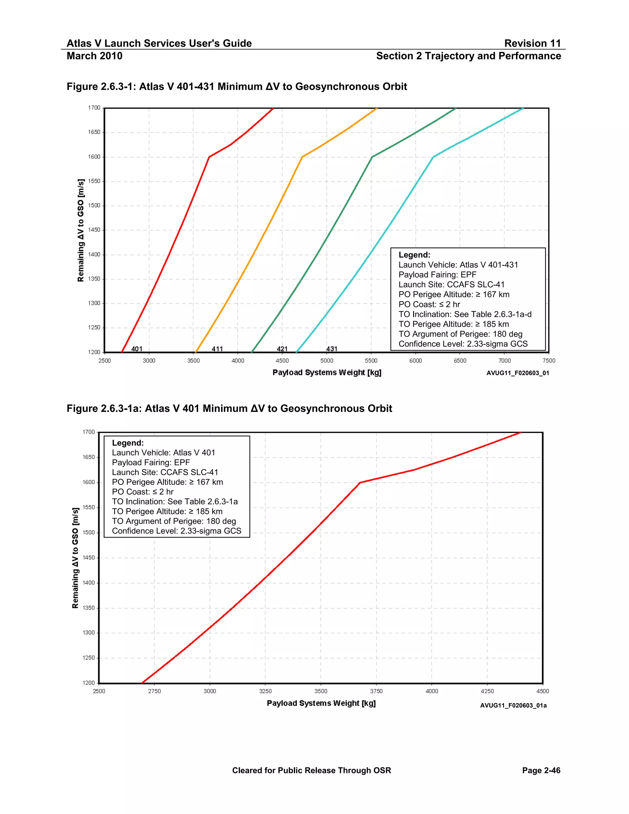
Table 2.6.3-1a: Atlas V 401 Minimum ΔV to Geosynchronous Orbit — Apogee Cap
ΔV to
GSO
[m/s]
1,700
1,675
1,650
1,625
1,600
1,575
1,550
1,525
1,500
1,475
1,450
1,425
1,400
1,375
1,350
1,325
1,300
1,275
1,250
1,225
1,200
Atlas V 401 GTO — ΔV to GSO at 35,786 km (19,323 nmi)
True
Payload Systems
Perigee
Inclination
Anomaly
Weight
[km]
[nmi]
[deg]
[deg]
[kg]
[lb]
236
128
22.1
28.1
4,444
9,797
242
131
20.8
28.2
4,249
9,368
306
165
19.6
30.6
4,092
9,021
520
281
19.2
37.7
3,919
8,639
3,759
2,029
26.2
134.2
3,678
8,108
4,074
2,200
25.8
133.6
3,624
7,989
4,400
2,376
25.4
132.9
3,570
7,870
4,694
2,534
24.9
131.7
3,515
7,750
4,978
2,688
24.4
130.5
3,460
7,620
5,306
2,865
24.0
129.2
3,402
7,501
5,632
3,041
23.5
127.8
3,344
7,373
5,947
3,211
23.1
126.4
3,285
7,243
6,264
3,382
22.6
125.1
3,225
7,110
6,582
3,554
22.2
123.6
3,164
6,975
6,938
3,746
21.7
122.0
3,101
6,837
7,254
3,917
21.3
120.6
3,037
6,695
7,563
4,083
20.8
119.2
2,971
6,550
7,896
4,264
20.3
117.6
2,904
6,402
8,194
4,424
19.8
116.1
2,835
6,250
8,498
4,588
19.3
114.5
2,765
6,095
8,792
4,747
18.9
113.0
2,692
5,935
Longitude
[deg]
19.9
20.3
22.4
28.1
90.2
90.3
90.3
90.6
90.8
90.8
91.0
91.1
91.3
91.5
91.7
91.9
92.1
92.3
92.6
92.8
93.0
Latitude
[deg]
-10.3
-9.7
-9.9
-11.7
-18.6
-18.5
-18.4
-18.5
-18.4
-18.5
-18.5
-18.5
-18.5
-18.4
-18.4
-18.3
-18.2
-18.1
-17.9
-17.7
-17.4
Notes:
Launch Site: CCAFS SLC-41
Park Orbit Perigee Altitude ≥ 167 km (90 nmi)
Park Orbit Coast ≤ 2 Hours
Transfer Orbit Perigee Altitude ≥ 185 km (100 nmi)
Transfer Orbit Argument of Perigee = 180 deg
Confidence Level: 2.33 Sigma GCS
Apogee is at 1st SC Apogee, Perigee and Inclination are at SC Separation, True Anomaly is at Injection
Latitude and East Longitude are taken at SC Separation
Only oblate Earth effects were taken into account when propagating to 1st SC Apogee
Cleared for Public Release Through OSR
Page 2-47](https://image.slidesharecdn.com/atlasvusersguide2010-140220084057-phpapp02/75/Atlas-v-usersguide2010-77-2048.jpg)
![Atlas V Launch Services User's Guide
March 2010
Revision 11
Section 2 Trajectory and Performance
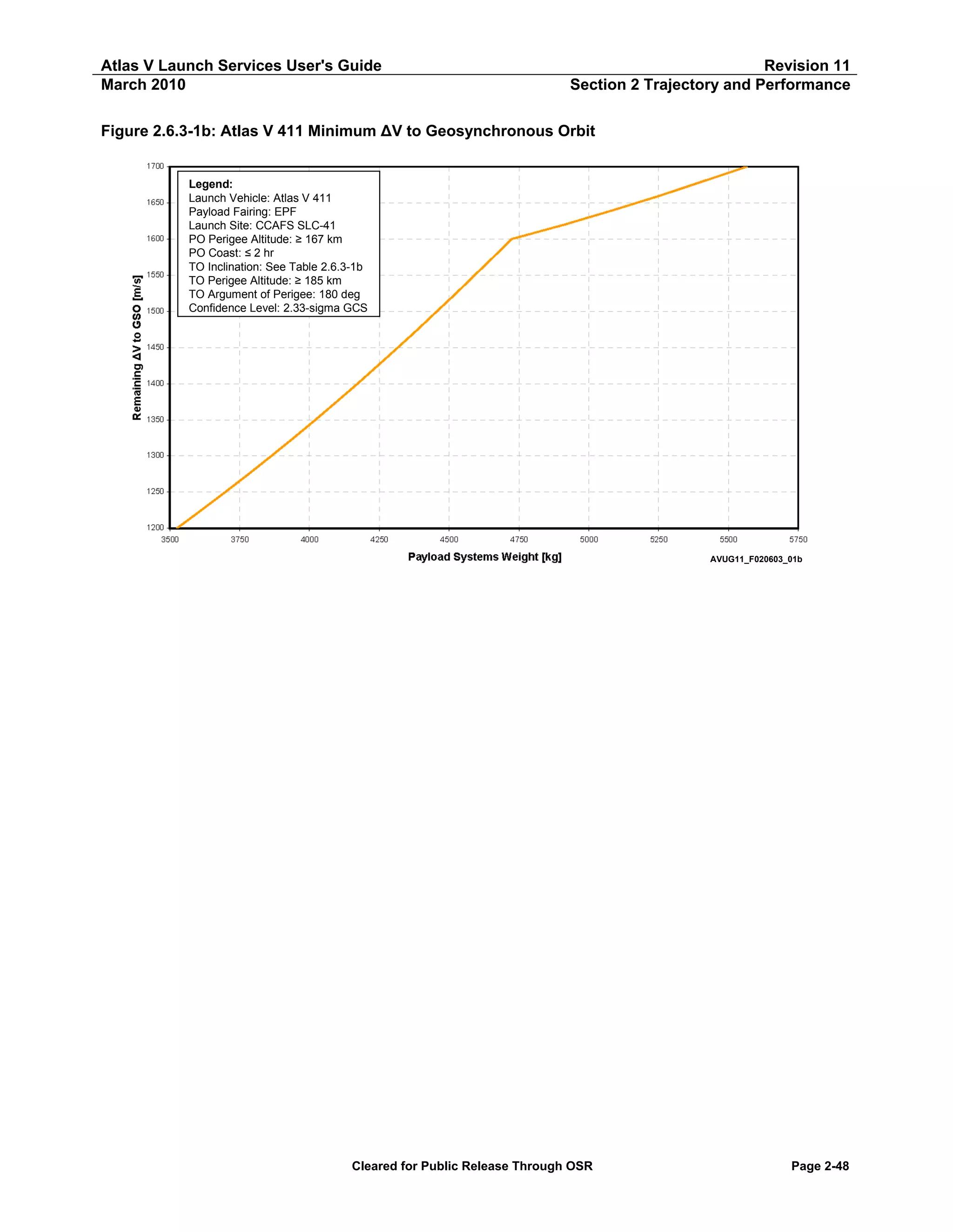
Table 2.6.3-1b: Atlas V 411 Minimum ΔV to Geosynchronous Orbit — Apogee Cap
ΔV to GSO
[m/s]
1,700
1,660
1,640
1,620
1,600
1,575
1,550
1,525
1,500
1,475
1,450
1,425
1,400
1,375
1,350
1,325
1,300
1,275
1,250
1,225
1,200
Atlas V 411 GTO — ΔV to GSO at 35,786 km (19,323 nmi)
True
Payload Systems
Perigee
Inclination
Anomaly
Weight
[km]
[nmi]
[deg]
[deg]
[kg]
[lb]
222
120
22.0
27.7
5,566
12,272
248
134
20.0
29.3
5,255
11,586
365
197
19.3
33.1
5,088
11,216
625
338
19.4
41.0
4,915
10,835
3,802
2,053
26.3
134.4
4,724
10,415
4,085
2,206
25.8
134.2
4,658
10,270
4,397
2,374
25.4
133.0
4,592
10,123
4,703
2,540
24.9
131.8
4,525
9,975
5,016
2,708
24.5
130.5
4,450
9,810
5,341
2,884
24.0
129.2
4,387
9,672
5,670
3,062
23.6
127.8
4,317
9,517
6,006
3,243
23.1
126.4
4,245
9,359
6,351
3,429
22.7
124.9
4,172
9,197
6,638
3,584
22.2
123.6
4,097
9,033
6,996
3,777
21.8
122.0
4,021
8,865
7,314
3,949
21.3
120.5
3,943
8,694
7,630
4,120
20.8
119.0
3,864
8,518
7,976
4,307
20.4
117.4
3,782
8,338
8,265
4,463
19.9
115.9
3,698
8,153
8,573
4,629
19.4
114.3
3,612
7,964
8,839
4,773
18.9
112.9
3,525
7,771
Longitude
[deg]
19.8
21.5
24.6
31.1
91.2
91.3
91.5
91.6
91.7
91.8
92.0
92.1
92.3
92.5
92.7
92.9
93.1
93.3
93.6
93.9
94.2
Latitude
[deg]
-10.1
-9.7
-10.5
-12.6
-18.6
-18.3
-18.4
-18.4
-18.5
-18.5
-18.5
-18.6
-18.6
-18.5
-18.5
-18.4
-18.2
-18.1
-17.9
-17.7
-17.5
Notes:
Launch Site: CCAFS SLC-41
Park Orbit Perigee Altitude ≥ 167 km (90 nmi)
Park Orbit Coast ≤ 2 Hours
Transfer Orbit Perigee Altitude ≥ 185 km (100 nmi)
Transfer Orbit Argument of Perigee = 180 deg
Confidence Level: 2.33 Sigma GCS
Apogee is at 1st SC Apogee, Perigee and Inclination are at SC Separation, True Anomaly is at Injection
Latitude and East Longitude are taken at SC Separation
Only oblate Earth effects were taken into account when propagating to 1st SC Apogee
Cleared for Public Release Through OSR
Page 2-49](https://image.slidesharecdn.com/atlasvusersguide2010-140220084057-phpapp02/75/Atlas-v-usersguide2010-79-2048.jpg)
![Atlas V Launch Services User's Guide
March 2010
Revision 11
Section 2 Trajectory and Performance
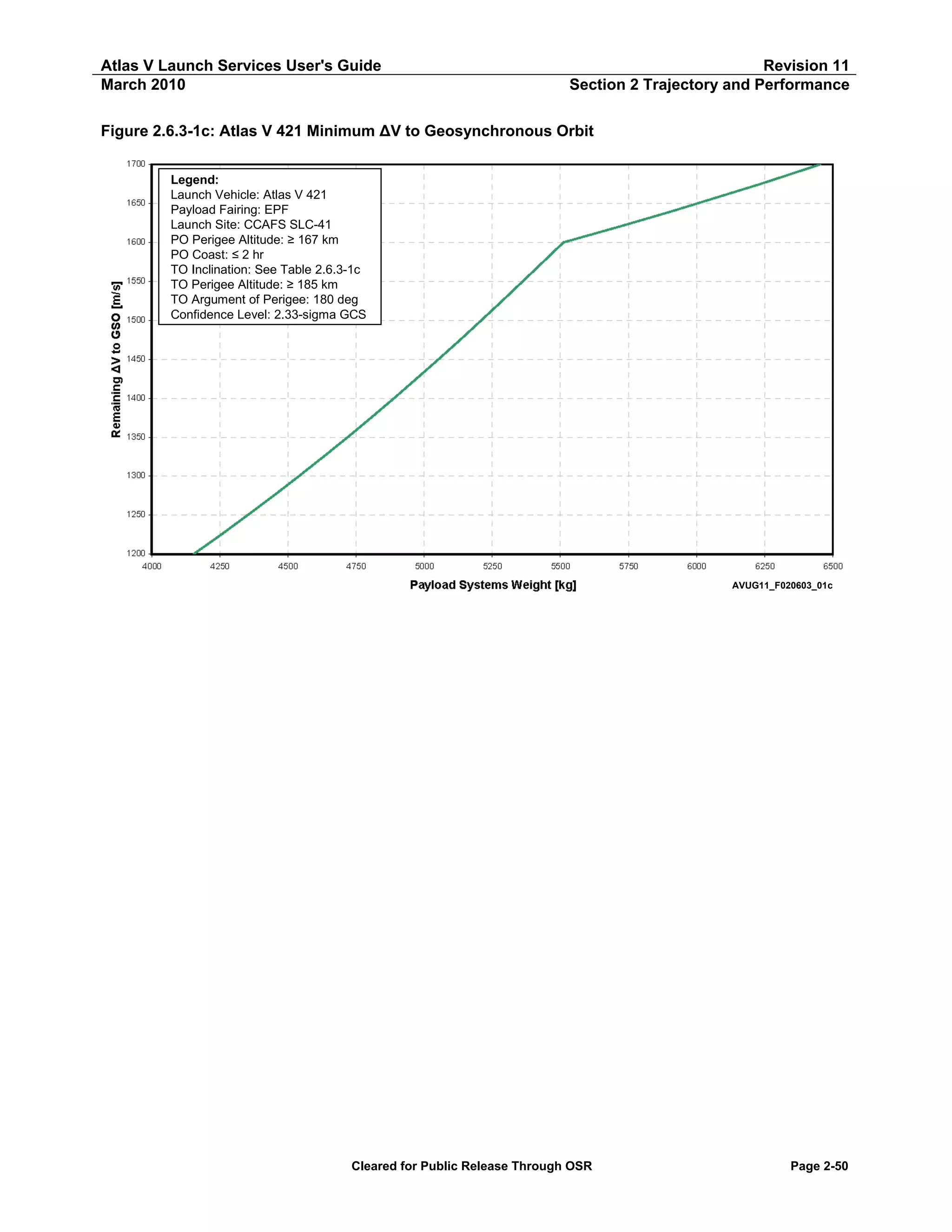
Table 2.6.3-1c: Atlas V 421 Minimum ΔV to Geosynchronous Orbit — Apogee Cap
ΔV to GSO
[m/s]
1,700
1,675
1,640
1,620
1,600
1,575
1,550
1,525
1,500
1,475
1,450
1,425
1,400
1,375
1,350
1,325
1,300
1,275
1,250
1,225
1,200
Atlas V 421 GTO — ΔV to GSO at 35,786 km (19,323 nmi)
True
Payload Systems
Perigee
Inclination
Anomaly
Weight
[km]
[nmi]
[deg]
[deg]
[kg]
[lb]
218
118
22.0
28.3
6,454
14,228
230
124
20.7
28.7
6,237
13,750
382
206
19.4
34.0
5,910
13,028
660
356
19.5
41.8
5,715
12,600
3,827
2,066
26.3
134.2
5,511
12,151
4,158
2,245
25.9
133.9
5,437
11,986
4,461
2,409
25.5
133.0
5,362
11,822
4,781
2,582
25.0
131.7
5,287
11,655
5,105
2,757
24.6
130.4
5,210
11,480
5,446
2,941
24.1
129.0
5,132
11,314
5,781
3,122
23.7
127.6
5,053
11,139
6,086
3,286
23.2
126.2
4,972
10,961
6,429
3,471
22.8
124.7
4,889
10,779
6,787
3,665
22.4
123.2
4,805
10,593
7,133
3,851
21.9
121.6
4,719
10,403
7,449
4,022
21.5
120.2
4,631
10,209
7,782
4,202
21.0
118.5
4,540
10,009
8,085
4,365
20.5
117.1
4,447
9,805
8,404
4,538
20.0
115.6
4,352
9,595
8,679
4,686
19.5
114.2
4,254
9,379
8,974
4,845
19.0
112.8
4,154
9,157
Longitude
[deg]
20.5
21.2
25.4
31.7
91.5
91.6
91.6
91.7
91.8
92.0
92.1
92.2
92.3
92.5
92.7
92.8
93.1
93.2
93.4
93.8
94.0
Latitude
[deg]
-10.3
-9.9
-10.8
-13.0
-18.7
-18.5
-18.4
-18.5
-18.6
-18.7
-18.7
-18.7
-18.7
-18.7
-18.7
-18.6
-18.5
-18.3
-18.1
-17.9
-17.6
Notes:
Launch Site: CCAFS SLC-41
Park Orbit Perigee Altitude ≥ 167 km (90 nmi)
Park Orbit Coast ≤ 2 Hours
Transfer Orbit Perigee Altitude ≥ 185 km (100 nmi)
Transfer Orbit Argument of Perigee = 180 deg
Confidence Level: 2.33 Sigma GCS
Apogee is at 1st SC Apogee, Perigee and Inclination are at SC Separation, True Anomaly is at Injection
Latitude and East Longitude are taken at SC Separation
Only oblate Earth effects were taken into account when propagating to 1st SC Apogee
Cleared for Public Release Through OSR
Page 2-51](https://image.slidesharecdn.com/atlasvusersguide2010-140220084057-phpapp02/75/Atlas-v-usersguide2010-81-2048.jpg)
![Atlas V Launch Services User's Guide
March 2010
Revision 11
Section 2 Trajectory and Performance
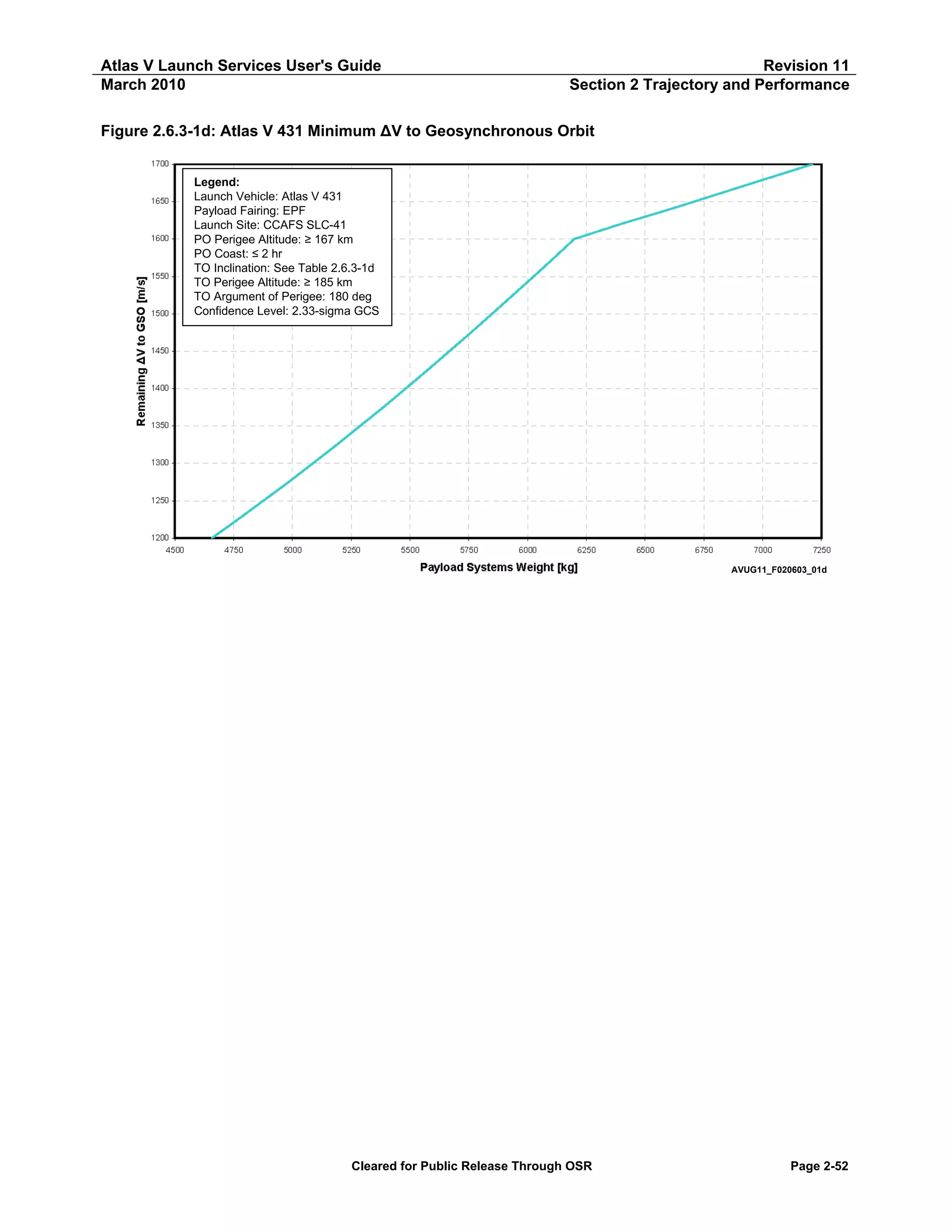
Table 2.6.3-1d: Atlas V 431 Minimum ΔV to Geosynchronous Orbit — Apogee Cap
ΔV to GSO
[m/s]
1,700
1,675
1,650
1,625
1,600
1,575
1,550
1,525
1,500
1,475
1,450
1,425
1,400
1,375
1,350
1,325
1,300
1,275
1,250
1,225
1,200
Atlas V 431 GTO — ΔV to GSO at 35,786 km (19,323 nmi)
True
Payload Systems
Perigee
Inclination
Anomaly
Weight
[km]
[nmi]
[deg]
[deg]
[kg]
[lb]
221
119
22.1
29.6
7,092
15,635
237
128
20.7
30.2
6,885
15,178
252
136
19.4
30.6
6,639
14,636
355
192
18.4
31.3
6,366
14,034
3,663
1,978
26.1
136.3
6,199
13,666
3,991
2,155
25.7
135.1
6,113
13,476
4,302
2,323
25.2
133.8
6,026
13,284
4,641
2,506
24.8
132.5
5,938
13,090
4,973
2,685
24.4
131.2
5,860
12,910
5,310
2,867
24.0
129.8
5,759
12,696
5,640
3,045
23.5
128.4
5,668
12,496
5,993
3,236
23.1
126.9
5,575
12,292
6,317
3,411
22.7
125.5
5,482
12,085
6,660
3,596
22.2
124.0
5,386
11,874
6,992
3,776
21.8
122.6
5,289
11,659
7,338
3,962
21.3
121.0
5,189
11,440
7,661
4,136
20.9
119.5
5,088
11,216
7,985
4,311
20.4
118.0
4,984
10,987
8,291
4,477
19.9
116.4
4,877
10,753
8,610
4,649
19.5
115.0
4,769
10,513
8,912
4,812
19.0
113.3
4,657
10,266
Longitude
[deg]
21.6
22.3
23.0
23.8
91.1
91.2
91.3
91.2
91.4
91.4
91.6
91.7
91.8
91.9
92.1
92.2
92.4
92.6
92.7
93.1
93.3
Latitude
[deg]
-10.8
-10.3
-9.8
-9.5
-17.8
-17.9
-18.0
-18.2
-18.2
-18.3
-18.4
-18.4
-18.4
-18.4
-18.3
-18.3
-18.2
-18.0
-17.9
-17.7
-17.5
Notes:
Launch Site: CCAFS SLC-41
Park Orbit Perigee Altitude ≥ 167 km (90 nmi)
Park Orbit Coast ≤ 2 Hours
Transfer Orbit Perigee Altitude ≥ 185 km (100 nmi)
Transfer Orbit Argument of Perigee = 180 deg
Confidence Level: 2.33 Sigma GCS
Apogee is at 1st SC Apogee, Perigee and Inclination are at SC Separation, True Anomaly is at Injection
Latitude and East Longitude are taken at SC Separation
Only oblate Earth effects were taken into account when propagating to 1st SC Apogee
Cleared for Public Release Through OSR
Page 2-53](https://image.slidesharecdn.com/atlasvusersguide2010-140220084057-phpapp02/75/Atlas-v-usersguide2010-83-2048.jpg)
![Atlas V Launch Services User's Guide
March 2010
Revision 11
Section 2 Trajectory and Performance
Figure 2.6.3-2: Atlas V 501-551 Minimum ΔV to Geosynchronous Orbit
1700
1650
Remaining ΔV to GSO [m/s]
1600
1550
1500
1450
1400
1350
1300
1250
50 1
1200
2000
511
2500
3000
52 1
3500
4000
53 1
4500
5000
54 1
5500
551
6000
Payload System s Weight [kg]
6500
7000
7500
8000
8500
AVUG11_F020603_02
Figure 2.6.3-2a: Atlas V 501 Minimum ΔV to Geosynchronous Orbit
Legend:
Launch Vehicle: Atlas V 501
Payload Fairing: 5-m Short
Launch Site: CCAFS SLC-41
PO Perigee Altitude: ≥ 167 km
PO Coast: ≤ 2 hr
TO Inclination: See Table 2.6.3-2a
TO Perigee Altitude: ≥ 185 km
TO Argument of Perigee: 180 deg
Confidence Level: 2.33-sigma GCS
AVUG11_F020603_02a
Cleared for Public Release Through OSR
Page 2-54](https://image.slidesharecdn.com/atlasvusersguide2010-140220084057-phpapp02/75/Atlas-v-usersguide2010-84-2048.jpg)
![Atlas V Launch Services User's Guide
March 2010
Revision 11
Section 2 Trajectory and Performance
Table 2.6.3-2a: Atlas V 501 Minimum ΔV to Geosynchronous Orbit — Apogee Cap
ΔV to GSO
[m/s]
1,700
1,675
1,650
1,625
1,600
1,575
1,550
1,525
1,500
1,475
1,450
1,425
1,400
1,375
1,350
1,325
1,300
1,275
1,250
1,225
1,200
Atlas V 501 GTO — ΔV to GSO at 35,786 km (19,323 nmi)
True
Payload Systems
Perigee
Inclination
Anomaly
Weight
[km]
[nmi]
[deg]
[deg]
[kg]
[lb]
250
135
22.1
27.7
3,392
7,478
277
149
20.9
28.7
3,282
7,236
303
164
19.6
29.4
3,143
6,929
370
200
18.5
31.1
2,982
6,573
3,580
1,933
26.0
135.7
2,869
6,326
3,840
2,073
25.5
134.6
2,823
6,224
4,135
2,233
25.0
133.5
2,776
6,120
4,547
2,455
24.7
131.7
2,723
6,003
4,816
2,601
24.2
130.6
2,690
5,930
5,086
2,746
23.7
129.5
2,635
5,808
5,417
2,925
23.3
128.1
2,586
5,700
5,744
3,101
22.8
126.6
2,531
5,580
6,062
3,273
22.4
125.2
2,472
5,449
6,307
3,406
21.8
124.1
2,409
5,312
6,649
3,590
21.4
122.7
2,361
5,204
6,953
3,754
20.9
121.2
2,302
5,074
7,245
3,912
20.4
120.0
2,252
4,964
7,560
4,082
20.0
118.1
2,185
4,818
7,961
4,298
19.6
116.5
2,131
4,699
8,246
4,452
19.1
115.1
2,075
4,575
8,480
4,579
18.5
113.8
2,018
4,449
Longitude
[deg]
26.2
28.3
28.6
31.5
91.5
91.7
92.0
91.9
92.3
92.5
92.7
92.4
93.4
93.5
93.8
93.3
93.6
94.6
94.6
94.8
95.0
Latitude
[deg]
-10.2
-9.9
-9.6
-9.5
-17.9
-17.9
-18.0
-18.3
-18.3
-18.2
-18.2
-18.3
-18.3
-18.1
-18.0
-17.9
-17.7
-17.7
-17.6
-17.3
-17.0
Notes:
Launch Site: CCAFS SLC-41
Park Orbit Perigee Altitude ≥ 167 km (90 nmi)
Park Orbit Coast ≤ 2 Hours
Transfer Orbit Perigee Altitude ≥ 185 km (100 nmi)
Transfer Orbit Argument of Perigee = 180 deg
Confidence Level: 2.33 Sigma GCS
Apogee is at 1st SC Apogee, Perigee and Inclination are at SC Separation, True Anomaly is at Injection
Latitude and East Longitude are taken at SC Separation
Only oblate Earth effects were taken into account when propagating to 1st SC Apogee
Cleared for Public Release Through OSR
Page 2-55](https://image.slidesharecdn.com/atlasvusersguide2010-140220084057-phpapp02/75/Atlas-v-usersguide2010-85-2048.jpg)
![Atlas V Launch Services User's Guide
March 2010
Revision 11
Section 2 Trajectory and Performance
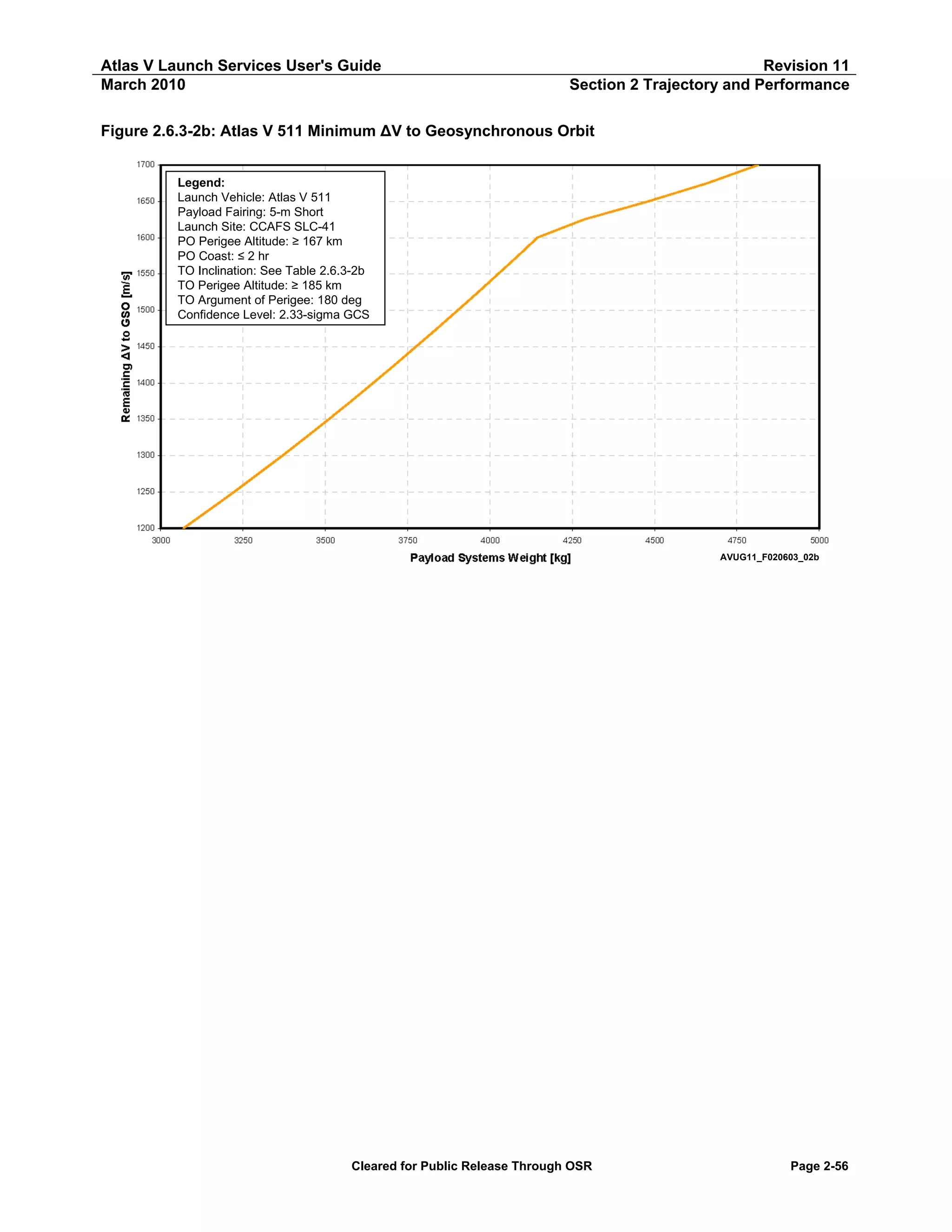
Table 2.6.3-2b: Atlas V 511 Minimum ΔV to Geosynchronous Orbit — Apogee Cap
ΔV to GSO
[m/s]
1,700
1,675
1,650
1,625
1,600
1,575
1,550
1,525
1,500
1,475
1,450
1,425
1,400
1,375
1,350
1,325
1,300
1,275
1,250
1,225
1,200
Atlas V 511 GTO — ΔV to GSO at 35,786 km (19,323 nmi)
True
Payload Systems
Perigee
Inclination
Anomaly
Weight
[km]
[nmi]
[deg]
[deg]
[kg]
[lb]
261
141
22.2
30.2
4,814
10,613
294
159
21.0
31.5
4,660
10,274
345
186
19.8
33.1
4,481
9,880
484
261
19.0
34.0
4,286
9,449
3,604
1,946
26.0
136.0
4,144
9,137
3,889
2,100
25.6
134.8
4,085
9,006
4,209
2,272
25.1
133.6
4,025
8,873
4,512
2,436
24.7
132.3
3,964
8,739
4,841
2,614
24.2
131.1
3,900
8,590
5,147
2,779
23.8
129.7
3,839
8,464
5,474
2,956
23.3
128.3
3,775
8,323
5,782
3,122
22.9
127.0
3,711
8,181
6,103
3,295
22.4
125.6
3,645
8,036
6,440
3,477
22.0
124.2
3,578
7,889
6,757
3,648
21.5
122.7
3,510
7,738
7,085
3,825
21.1
121.2
3,441
7,585
7,374
3,981
20.6
119.8
3,370
7,429
7,713
4,165
20.1
118.2
3,297
7,268
7,996
4,318
19.6
116.9
3,223
7,104
8,291
4,477
19.2
115.2
3,147
6,938
8,602
4,645
18.7
113.8
3,069
6,766
Longitude
[deg]
21.8
23.2
24.7
25.9
92.5
92.5
92.6
92.9
93.0
93.2
93.3
93.6
93.7
93.9
94.1
94.2
94.7
94.8
95.0
95.3
95.6
Latitude
[deg]
-11.0
-10.9
-10.8
-10.6
-17.9
-17.9
-18.0
-18.1
-18.1
-18.2
-18.2
-18.2
-18.2
-18.2
-18.1
-18.0
-17.9
-17.8
-17.6
-17.4
-17.1
Notes:
Launch Site: CCAFS SLC-41
Park Orbit Perigee Altitude ≥ 167 km (90 nmi)
Park Orbit Coast ≤ 2 Hours
Transfer Orbit Perigee Altitude ≥ 185 km (100 nmi)
Transfer Orbit Argument of Perigee = 180 deg
Confidence Level: 2.33 Sigma GCS
Apogee is at 1st SC Apogee, Perigee and Inclination are at SC Separation, True Anomaly is at Injection
Latitude and East Longitude are taken at SC Separation
Only oblate Earth effects were taken into account when propagating to 1st SC Apogee
Cleared for Public Release Through OSR
Page 2-57](https://image.slidesharecdn.com/atlasvusersguide2010-140220084057-phpapp02/75/Atlas-v-usersguide2010-87-2048.jpg)
![Atlas V Launch Services User's Guide
March 2010
Revision 11
Section 2 Trajectory and Performance
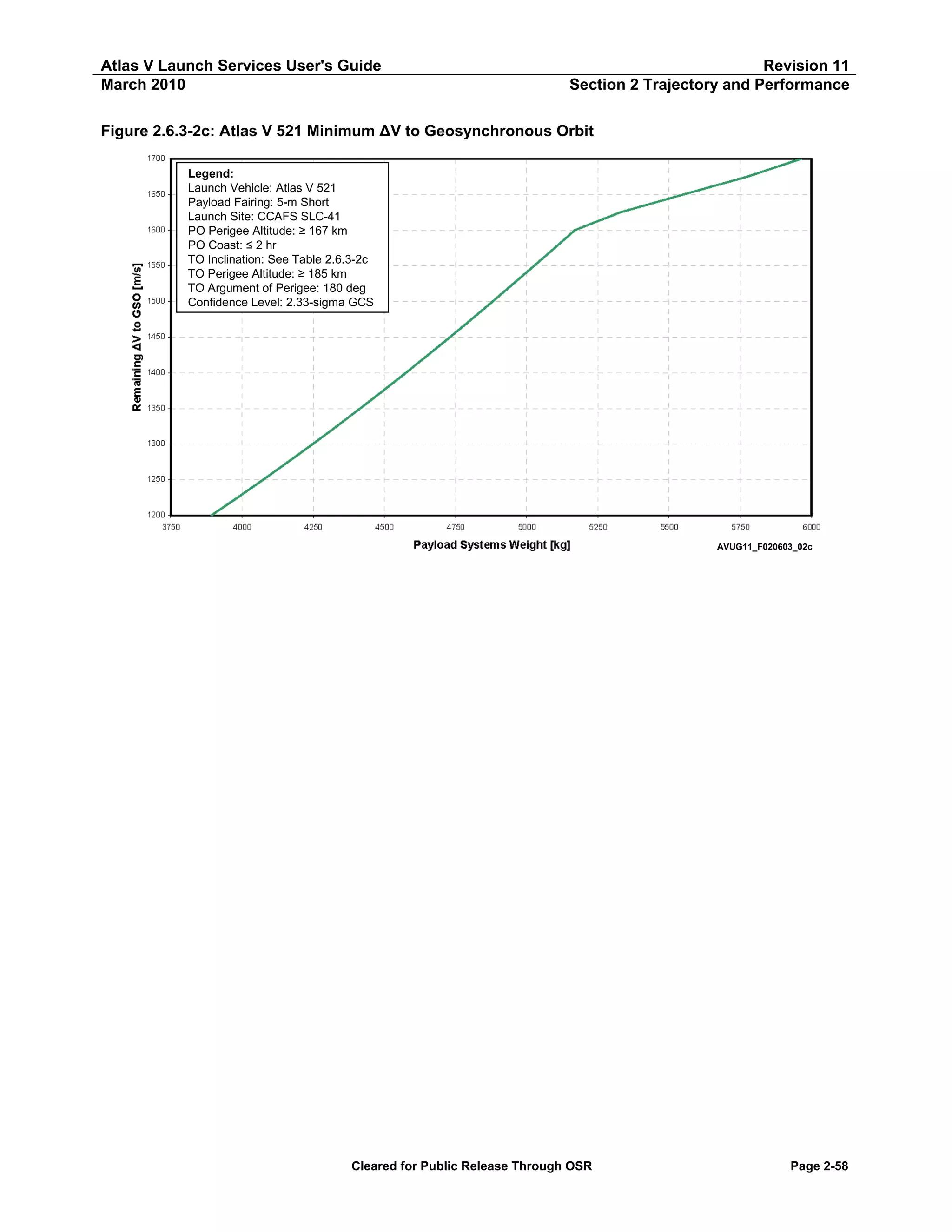
Table 2.6.3-2c: Atlas V 521 Minimum ΔV to Geosynchronous Orbit — Apogee Cap
ΔV to GSO
[m/s]
1,700
1,675
1,650
1,625
1,600
1,575
1,550
1,525
1,500
1,475
1,450
1,425
1,400
1,375
1,350
1,325
1,300
1,275
1,250
1,225
1,200
Atlas V 521 GTO — ΔV to GSO at 35,786 km (19,323 nmi)
True
Payload Systems
Perigee
Inclination
Anomaly
Weight
[km]
[nmi]
[deg]
[deg]
[kg]
[lb]
212
115
22.0
28.7
5,963
13,146
238
129
20.7
29.8
5,775
12,731
321
173
19.7
30.2
5,551
12,238
452
244
18.9
31.1
5,328
11,746
3,636
1,963
26.1
136.0
5,169
11,395
3,897
2,104
25.6
135.0
5,098
11,238
4,242
2,291
25.2
133.6
5,026
11,080
4,555
2,459
24.7
132.4
4,953
10,921
4,868
2,629
24.3
131.1
4,880
10,750
5,206
2,811
23.9
129.8
4,806
10,595
5,514
2,977
23.4
128.5
4,730
10,428
5,857
3,163
23.0
127.0
4,654
10,259
6,153
3,322
22.5
125.7
4,576
10,088
6,511
3,516
22.1
124.2
4,496
9,912
6,845
3,696
21.6
122.6
4,415
9,733
7,166
3,869
21.2
121.2
4,333
9,552
7,498
4,048
20.7
119.7
4,248
9,366
7,814
4,219
20.2
118.2
4,162
9,175
8,108
4,378
19.8
116.7
4,074
8,981
8,379
4,524
19.2
115.3
3,984
8,783
8,677
4,685
18.7
113.8
3,892
8,580
Longitude
[deg]
20.8
22.0
22.8
23.9
92.8
93.1
93.0
93.2
93.2
93.3
93.6
93.7
93.9
94.0
94.2
94.4
94.6
94.6
95.0
95.3
95.5
Latitude
[deg]
-10.4
-10.2
-9.8
-9.7
-17.9
-17.9
-18.0
-18.1
-18.2
-18.2
-18.2
-18.3
-18.2
-18.2
-18.2
-18.1
-18.0
-17.9
-17.7
-17.4
-17.2
Notes:
Launch Site: CCAFS SLC-41
Park Orbit Perigee Altitude ≥ 167 km (90 nmi)
Park Orbit Coast ≤ 2 Hours
Transfer Orbit Perigee Altitude ≥ 185 km (100 nmi)
Transfer Orbit Argument of Perigee = 180 deg
Confidence Level: 2.33 Sigma GCS
Apogee is at 1st SC Apogee, Perigee and Inclination are at SC Separation, True Anomaly is at Injection
Latitude and East Longitude are taken at SC Separation
Only oblate Earth effects were taken into account when propagating to 1st SC Apogee
Cleared for Public Release Through OSR
Page 2-59](https://image.slidesharecdn.com/atlasvusersguide2010-140220084057-phpapp02/75/Atlas-v-usersguide2010-89-2048.jpg)
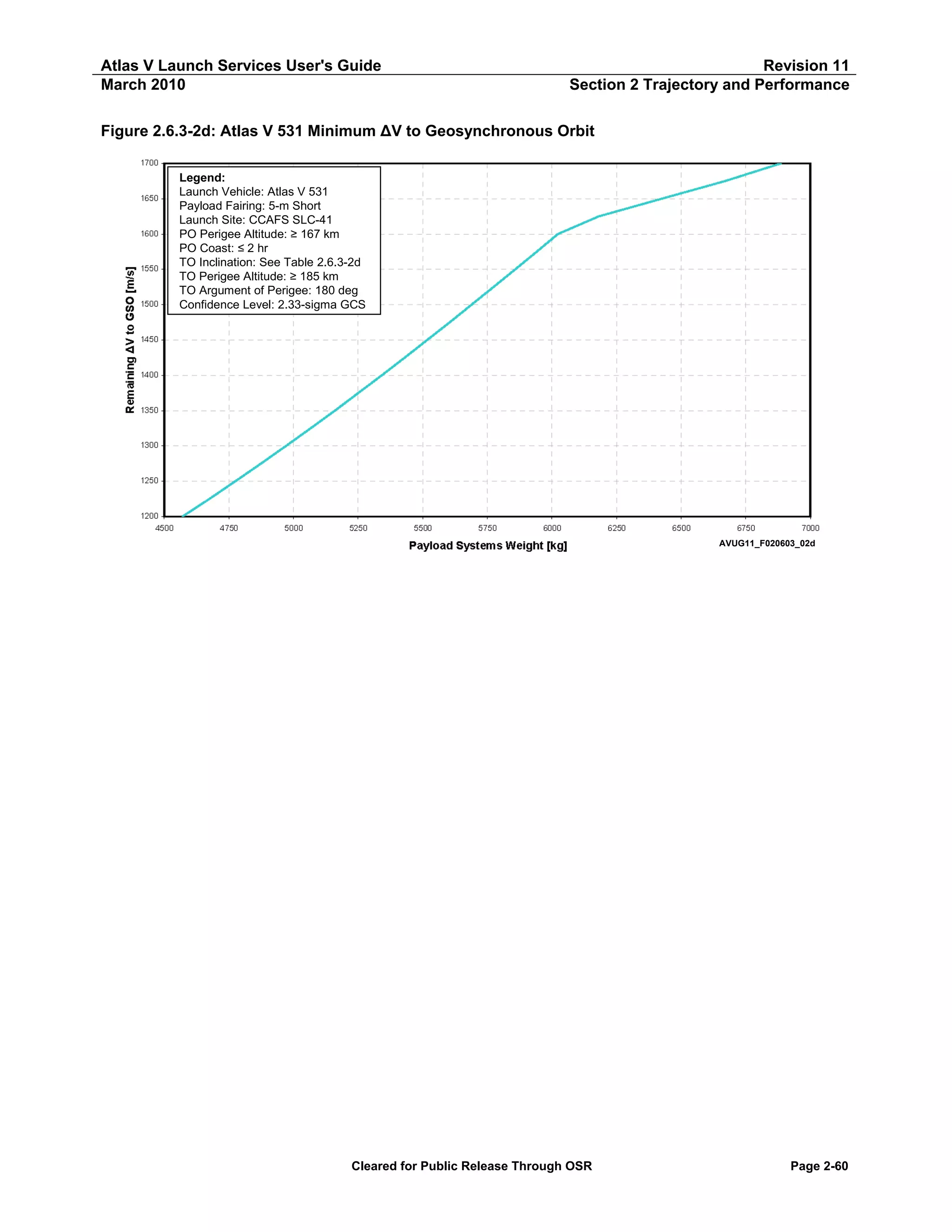
![Atlas V Launch Services User's Guide
March 2010
Revision 11
Section 2 Trajectory and Performance
Table 2.6.3-2d: Atlas V 531 Minimum ΔV to Geosynchronous Orbit — Apogee Cap
ΔV to
GSO
[m/s]
1,700
1,675
1,650
1,625
1,600
1,575
1,550
1,525
1,500
1,475
1,450
1,425
1,400
1,375
1,350
1,325
1,300
1,275
1,250
1,225
1,200
Atlas V 531 GTO — ΔV to GSO at 35,786 km (19,323 nmi)
True
Payload Systems
Perigee
Inclination
Anomaly
Weight
[km]
[nmi]
[deg]
[deg]
[kg]
[lb]
242
131
22.1
30.7
6,886
15,180
267
144
20.9
31.4
6,671
14,706
368
199
19.9
32.1
6,426
14,167
531
287
19.2
32.5
6,180
13,626
3,517
1,899
25.9
136.7
6,023
13,278
3,821
2,063
25.5
135.5
5,941
13,097
4,150
2,241
25.0
134.2
5,858
12,914
4,458
2,407
24.6
133.0
5,774
12,730
4,769
2,575
24.1
131.8
5,690
12,540
5,102
2,755
23.7
130.4
5,604
12,355
5,425
2,929
23.3
129.1
5,518
12,166
5,746
3,103
22.8
127.8
5,430
11,972
6,086
3,286
22.4
126.3
5,342
11,777
6,401
3,456
22.0
124.9
5,252
11,578
6,738
3,638
21.5
123.5
5,160
11,376
7,080
3,823
21.1
122.0
5,067
11,170
7,396
3,993
20.6
120.5
4,971
10,960
7,715
4,166
20.1
119.0
4,875
10,747
8,016
4,328
19.7
117.5
4,776
10,529
8,324
4,494
19.2
116.1
4,675
10,306
8,589
4,637
18.7
114.6
4,570
10,075
Longitude
[deg]
22.5
23.4
24.4
25.1
92.5
92.6
92.7
92.8
92.8
93.0
93.1
93.3
93.4
93.5
93.7
93.9
94.1
94.2
94.5
94.6
95.0
Latitude
[deg]
-11.2
-10.8
-10.5
-10.3
-17.5
-17.6
-17.8
-17.8
-17.9
-17.9
-18.0
-18.0
-18.0
-18.0
-17.9
-17.9
-17.8
-17.6
-17.5
-17.3
-17.0
Notes:
Launch Site: CCAFS SLC-41
Park Orbit Perigee Altitude ≥ 167 km (90 nmi)
Park Orbit Coast ≤ 2 Hours
Transfer Orbit Perigee Altitude ≥ 185 km (100 nmi)
Transfer Orbit Argument of Perigee = 180 deg
Confidence Level: 2.33 Sigma GCS
Apogee is at 1st SC Apogee, Perigee and Inclination are at SC Separation, True Anomaly is at Injection
Latitude and East Longitude are taken at SC Separation
Only oblate Earth effects were taken into account when propagating to 1st SC Apogee
Cleared for Public Release Through OSR
Page 2-61](https://image.slidesharecdn.com/atlasvusersguide2010-140220084057-phpapp02/75/Atlas-v-usersguide2010-91-2048.jpg)
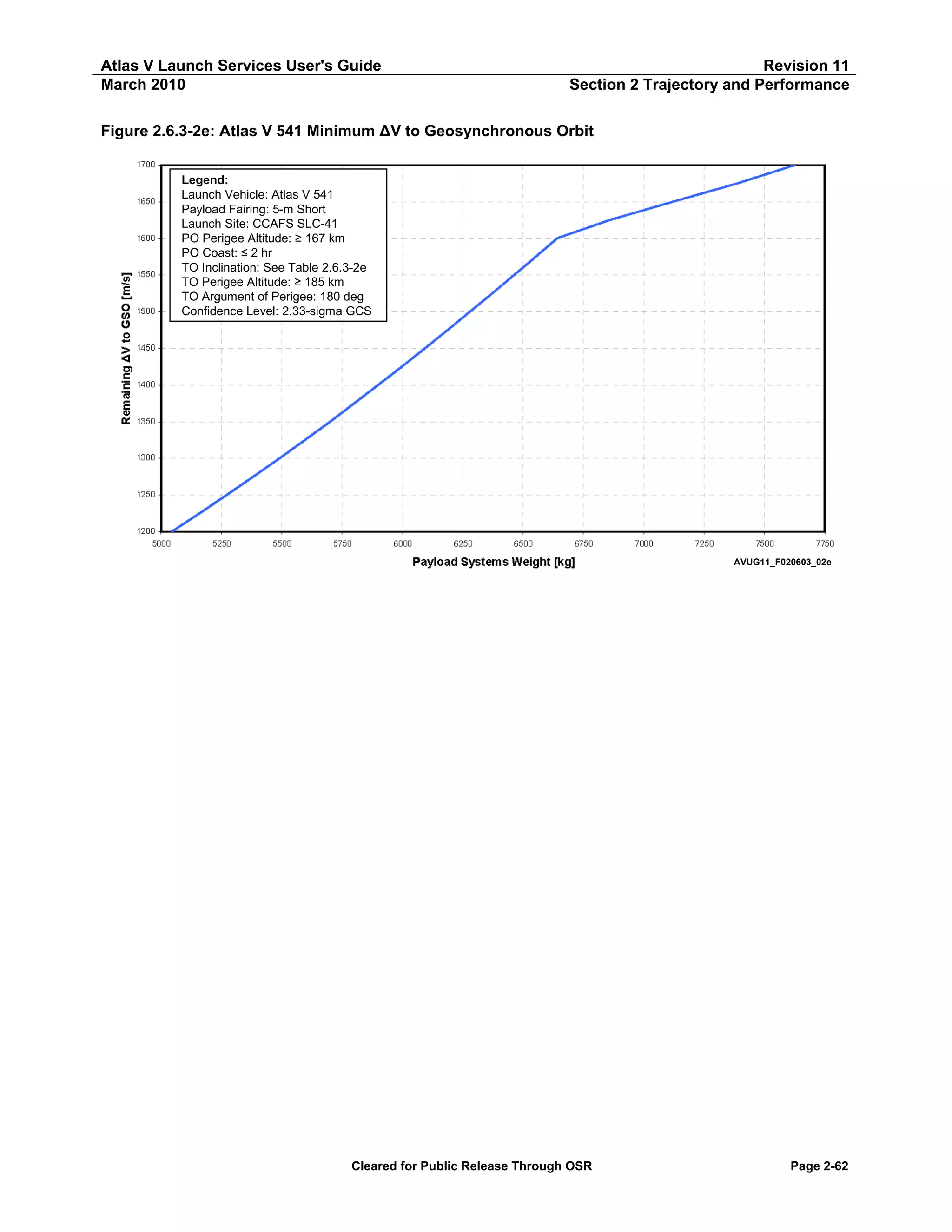
![Atlas V Launch Services User's Guide
March 2010
Revision 11
Section 2 Trajectory and Performance
Table 2.6.3-2e: Atlas V 541 Minimum ΔV to Geosynchronous Orbit — Apogee Cap
ΔV to
GSO
[m/s]
1,700
1,675
1,650
1,625
1,600
1,575
1,550
1,525
1,500
1,475
1,450
1,425
1,400
1,375
1,350
1,325
1,300
1,275
1,250
1,225
1,200
Atlas V 541 GTO — ΔV to GSO at 35,786 km (19,323 nmi)
True
Payload Systems
Perigee
Inclination
Anomaly
Weight
[km]
[nmi]
[deg]
[deg]
[kg]
[lb]
229
124
22.1
31.0
7,624
16,809
259
140
20.8
31.7
7,387
16,286
407
220
20.1
32.2
7,121
15,700
561
303
19.4
32.8
6,859
15,121
3,706
2,001
26.2
135.7
6,641
14,641
4,042
2,183
25.8
134.7
6,552
14,445
4,347
2,347
25.3
133.6
6,462
14,247
4,688
2,532
24.9
132.2
6,372
14,048
4,982
2,690
24.4
131.0
6,280
13,840
5,361
2,895
24.0
129.5
6,187
13,640
5,664
3,058
23.6
128.2
6,093
13,432
6,007
3,243
23.1
126.7
5,997
13,221
6,357
3,433
22.7
125.3
5,899
13,006
6,676
3,605
22.3
123.8
5,800
12,787
7,005
3,782
21.8
122.4
5,699
12,565
7,344
3,965
21.4
120.9
5,596
12,338
7,654
4,133
20.9
119.4
5,490
12,104
7,980
4,309
20.4
117.8
5,383
11,866
8,267
4,464
19.9
116.5
5,272
11,622
8,577
4,631
19.4
114.9
5,159
11,374
8,818
4,761
18.9
113.7
5,043
11,118
Longitude
[deg]
22.8
23.7
24.7
25.4
92.8
92.8
92.9
93.0
93.0
93.0
93.3
93.4
93.4
93.6
93.8
93.9
94.1
94.3
94.5
94.8
95.0
Latitude
[deg]
-11.2
-10.8
-10.6
-10.4
-18.0
-18.1
-18.2
-18.3
-18.3
-18.4
-18.4
-18.5
-18.5
-18.5
-18.4
-18.3
-18.2
-18.1
-17.9
-17.7
-17.3
Notes:
Launch Site: CCAFS SLC-41
Park Orbit Perigee Altitude ≥ 167 km (90 nmi)
Park Orbit Coast ≤ 2 Hours
Transfer Orbit Perigee Altitude ≥ 185 km (100 nmi)
Transfer Orbit Argument of Perigee = 180 deg
Confidence Level: 2.33 Sigma GCS
Apogee is at 1st SC Apogee, Perigee and Inclination are at SC Separation, True Anomaly is at Injection
Latitude and East Longitude are taken at SC Separation
Only oblate Earth effects were taken into account when propagating to 1st SC Apogee
Cleared for Public Release Through OSR
Page 2-63](https://image.slidesharecdn.com/atlasvusersguide2010-140220084057-phpapp02/75/Atlas-v-usersguide2010-93-2048.jpg)
![Atlas V Launch Services User's Guide
March 2010
Revision 11
Section 2 Trajectory and Performance
Figure 2.6.3-2f: Atlas V 551 Minimum ΔV to Geosynchronous Orbit
1700
1650
1600
Remaining ΔV GSO [m/s]
1550
1500
Legend:
Leg end :
Launch Vehicle: At las V 551 551
Launch Vehicle: Atlas V
Payload Fairing: 5-m Short
Payload Fairing: 5-m Short
Launch SitSite: CCAFS SLC-41
Launch e: CCAFS SLC-41
PO Perigee AltAltitude: ≥ 167 km
PO Perigee it ude: ≥ 167 km
PO Coast : ≤ 2 hr hr
PO Coast: ≤ 2
TO Inclinat ion: See Table 2.6.3-2f
TO Inclination: See Table 2.6.3-2f
TO Perigee Alt it ude: ≥ 185 km
TO Perigee Altitude: ≥ 185 km
TO Argument of Perigee: 180 deg
TO Argument of Perigee: 180 deg
Conf idence Level: 2.33-sigma GCS
Confidence Level: 2.33-sigma GCS
1450
1400
1350
1300
1250
1200
5500
5750
6000
6250
6500
6750
7000
7250
P aPayloadS ys t e m sWeight [kg]k g]
ylo a d Systems We ight [
Cleared for Public Release Through OSR
7500
7750
8000
8250
8500
AVUG11_F020603_02f
Page 2-64](https://image.slidesharecdn.com/atlasvusersguide2010-140220084057-phpapp02/75/Atlas-v-usersguide2010-94-2048.jpg)
![Atlas V Launch Services User's Guide
March 2010
Revision 11
Section 2 Trajectory and Performance
Table 2.6.3-2f: Atlas V 551 Minimum ΔV to Geosynchronous Orbit — Apogee Cap
ΔV to
GSO
[m/s]
1,700
1,675
1,650
1,625
1,600
1,575
1,550
1,525
1,500
1,475
1,450
1,425
1,400
1,375
1,350
1,325
1,300
1,275
1,250
1,225
1,200
Atlas V 551 GTO — ΔV to GSO at 35,786 km (19,323 nmi)
True
Payload Systems
Perigee
Inclination
Anomaly
Weight
[km]
[nmi]
[deg]
[deg]
[kg]
[lb]
206
111
22.0
30.3
8,366
18,445
280
151
20.9
32.9
8,084
17,822
433
234
20.2
33.5
7,798
17,193
599
323
19.5
33.8
7,517
16,572
3,532
1,907
25.9
136.9
7,266
16,020
3,844
2,075
25.5
135.7
7,166
15,798
4,167
2,250
25.1
134.5
7,065
15,575
4,493
2,426
24.6
133.2
6,963
15,350
4,824
2,605
24.2
131.9
6,860
15,120
5,152
2,782
23.8
130.5
6,756
14,895
5,477
2,958
23.4
129.2
6,652
14,665
5,834
3,150
22.9
127.8
6,545
14,430
6,171
3,332
22.5
126.3
6,438
14,193
6,476
3,497
22.0
125.0
6,329
13,952
6,892
3,721
21.7
123.1
6,217
13,707
7,189
3,882
21.2
121.9
6,105
13,458
7,499
4,049
20.7
120.4
5,990
13,205
7,819
4,222
20.2
118.8
5,872
12,946
8,105
4,376
19.7
117.4
5,752
12,682
8,436
4,555
19.3
115.7
5,629
12,410
8,716
4,706
18.8
114.5
5,505
12,137
Longitude
[deg]
22.3
24.6
25.6
26.1
92.3
92.4
92.5
92.5
92.6
92.7
92.8
92.9
93.0
93.2
93.3
93.4
93.6
93.8
94.0
94.4
94.4
Latitude
[deg]
-10.9
-11.3
-11.1
-10.8
-17.5
-17.6
-17.7
-17.8
-17.9
-18.0
-18.0
-18.1
-18.1
-18.0
-18.1
-18.0
-17.9
-17.8
-17.6
-17.4
-17.1
Notes:
Launch Site: CCAFS SLC-41
Park Orbit Perigee Altitude ≥ 167 km (90 nmi)
Park Orbit Coast ≤ 2 Hours
Transfer Orbit Perigee Altitude ≥ 185 km (100 nmi)
Transfer Orbit Argument of Perigee = 180 deg
Confidence Level: 2.33 Sigma GCS
Apogee is at 1st SC Apogee, Perigee and Inclination are at SC Separation, True Anomaly is at Injection
Latitude and East Longitude are taken at SC Separation
Only oblate Earth effects were taken into account when propagating to 1st SC Apogee
Cleared for Public Release Through OSR
Page 2-65](https://image.slidesharecdn.com/atlasvusersguide2010-140220084057-phpapp02/75/Atlas-v-usersguide2010-95-2048.jpg)
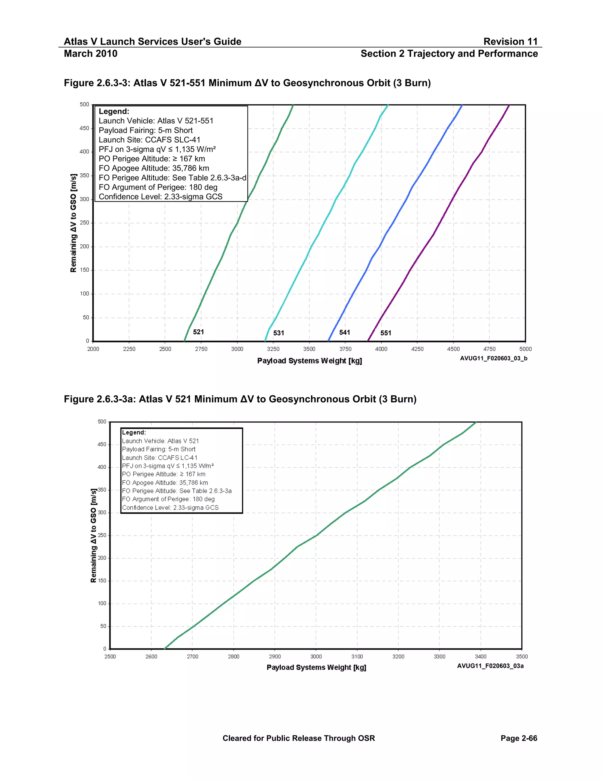
![Atlas V Launch Services User's Guide
March 2010
Revision 11
Section 2 Trajectory and Performance
Table 2.6.3-3a: Atlas V 521 Minimum ΔV to Geosynchronous Orbit (3 Burn) — Apogee Cap
ΔV to
GSO
[m/s]
500
475
450
425
400
375
350
325
300
275
250
225
200
175
150
125
100
75
50
25
0
Atlas V 521 GTO — ΔV to GSO at 35,786 km (19,323 nmi)
True
Payload Systems
Perigee
Inclination
Anomaly
Weight
[km]
[nmi]
[deg]
[deg]
[kg]
[lb]
17,722
9,569
4.3
-178.7
3,389
7,472
18,403
9,937
4.1
-179.0
3,355
7,397
19,076
10,300
3.9
-179.2
3,310
7,297
19,752
10,665
3.6
-178.5
3,276
7,222
20,321
10,972
3.2
-176.6
3,229
7,118
21,147
11,418
3.1
-178.8
3,196
7,045
22,006
11,882
2.9
-178.7
3,152
6,950
22,735
12,276
2.7
-179.1
3,118
6,874
23,340
12,602
2.2
176.3
3,072
6,772
24,198
13,066
2.0
179.9
3,035
6,691
25,251
13,635
2.0
-178.8
3,001
6,617
26,280
14,190
1.9
-179.3
2,955
6,514
27,079
14,621
1.6
-179.2
2,924
6,446
27,861
15,044
1.2
178.2
2,890
6,372
29,011
15,665
1.1
177.5
2,849
6,281
30,068
16,235
1.0
-178.2
2,813
6,202
31,186
16,839
0.8
-179.3
2,775
6,118
32,242
17,409
0.6
-178.9
2,740
6,040
33,382
18,025
0.4
-179.2
2,703
5,960
34,678
18,725
0.3
175.4
2,663
5,871
35,786
19,323
0.0
Undefined
2,632
5,802
Longitude
[deg]
95.2
95.5
95.2
95.4
95.4
95.4
95.2
95.4
95.0
95.4
95.5
95.4
95.7
95.3
95.4
95.4
95.5
95.6
95.6
95.4
95.5
Latitude
[deg]
0.1
0.1
0.1
0.1
0.2
0.1
0.1
0.0
-0.1
0.0
0.0
0.0
0.0
0.0
-0.1
0.0
0.0
0.0
0.0
0.0
0.0
Notes:
Launch Site: CCAFS SLC-41
Park Orbit Perigee Altitude ≥ 167 km (90 nmi)
Park Orbit Coast ≤ 2 Hours
Transfer Orbit Perigee Altitude ≥ 185 km (100 nmi)
Transfer Orbit Argument of Perigee = 180 deg
Confidence Level: 2.33 Sigma GCS
Apogee is at 1st SC Apogee, Perigee and Inclination are at SC Separation, True Anomaly is at Injection
Latitude and East Longitude are taken at SC Separation
Only oblate Earth effects were taken into account when propagating to 1st SC Apogee
Cleared for Public Release Through OSR
Page 2-67](https://image.slidesharecdn.com/atlasvusersguide2010-140220084057-phpapp02/75/Atlas-v-usersguide2010-97-2048.jpg)
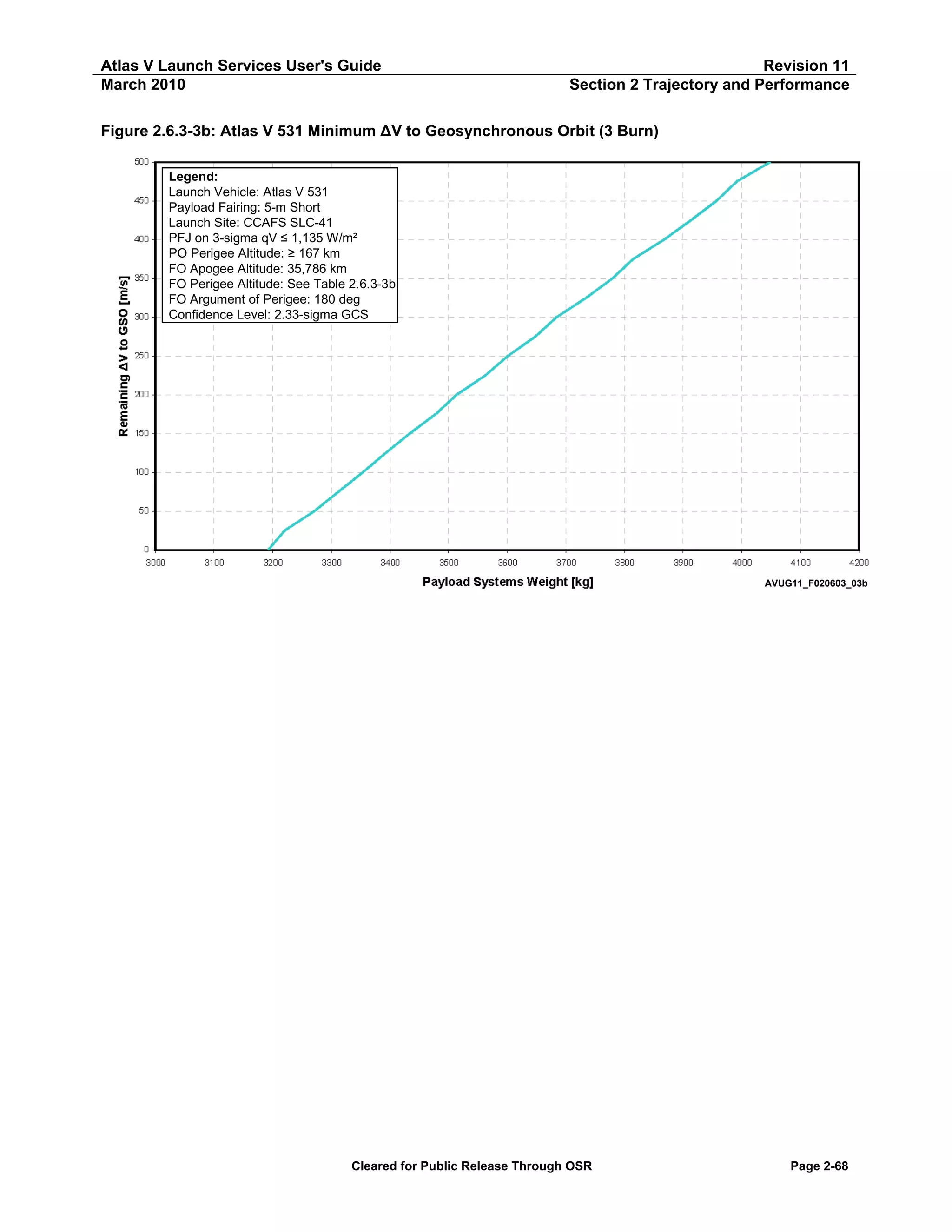
![Atlas V Launch Services User's Guide
March 2010
Revision 11
Section 2 Trajectory and Performance
Table 2.6.3-3b: Atlas V 531 Minimum ΔV to Geosynchronous Orbit (3 Burn) — Apogee Cap
ΔV to
GSO
[m/s]
500
475
450
425
400
375
350
325
300
275
250
225
200
175
150
125
100
75
50
25
0
Atlas V 531 GTO — ΔV to GSO at 35,786 km (19,323 nmi)
True
Payload Systems
Perigee
Inclination
Anomaly
Weight
[km]
[nmi]
[deg]
[deg]
[kg]
[lb]
17,772
9,596
4.4
-179.2
4,048
8,923
18,545
10,014
4.3
-179.4
3,991
8,799
19,073
10,299
3.8
-178.7
3,956
8,722
19,905
10,748
3.8
-178.7
3,913
8,626
20,466
11,051
3.4
-179.0
3,867
8,525
21,370
11,539
3.3
-179.5
3,815
8,410
21,977
11,867
2.9
-178.8
3,779
8,331
22,794
12,308
2.7
-179.2
3,735
8,234
23,510
12,694
2.4
-179.0
3,684
8,121
24,402
13,176
2.2
-178.9
3,648
8,042
25,171
13,591
1.9
-175.9
3,600
7,938
26,126
14,107
1.8
-178.5
3,562
7,854
26,974
14,565
1.5
-176.0
3,513
7,745
27,985
15,111
1.3
-178.0
3,478
7,667
29,041
15,681
1.2
-177.8
3,433
7,568
30,102
16,254
1.0
-178.4
3,392
7,479
31,089
16,787
0.7
179.7
3,354
7,393
32,252
17,415
0.6
-178.7
3,312
7,302
33,395
18,032
0.4
-178.9
3,271
7,211
35,014
18,906
0.4
163.0
3,220
7,100
35,786
19,323
0.0
Undefined
3,192
7,037
Longitude
[deg]
95.6
95.2
95.6
95.3
95.5
95.1
95.4
95.5
95.2
95.4
95.4
95.4
95.4
95.5
95.5
95.4
95.4
95.4
95.4
94.8
95.5
Latitude
[deg]
0.1
0.0
0.1
0.1
0.1
0.0
0.1
0.0
0.0
0.0
0.1
0.0
0.1
0.0
0.0
0.0
0.0
0.0
0.0
-0.1
0.0
Notes:
Launch Site: CCAFS SLC-41
Park Orbit Perigee Altitude ≥ 167 km (90 nmi)
Park Orbit Coast ≤ 2 Hours
Transfer Orbit Perigee Altitude ≥ 185 km (100 nmi)
Transfer Orbit Argument of Perigee = 180 deg
Confidence Level: 2.33 Sigma GCS
Apogee is at 1st SC Apogee, Perigee and Inclination are at SC Separation, True Anomaly is at Injection
Latitude and East Longitude are taken at SC Separation
Only oblate Earth effects were taken into account when propagating to 1st SC Apogee
Cleared for Public Release Through OSR
Page 2-69](https://image.slidesharecdn.com/atlasvusersguide2010-140220084057-phpapp02/75/Atlas-v-usersguide2010-99-2048.jpg)
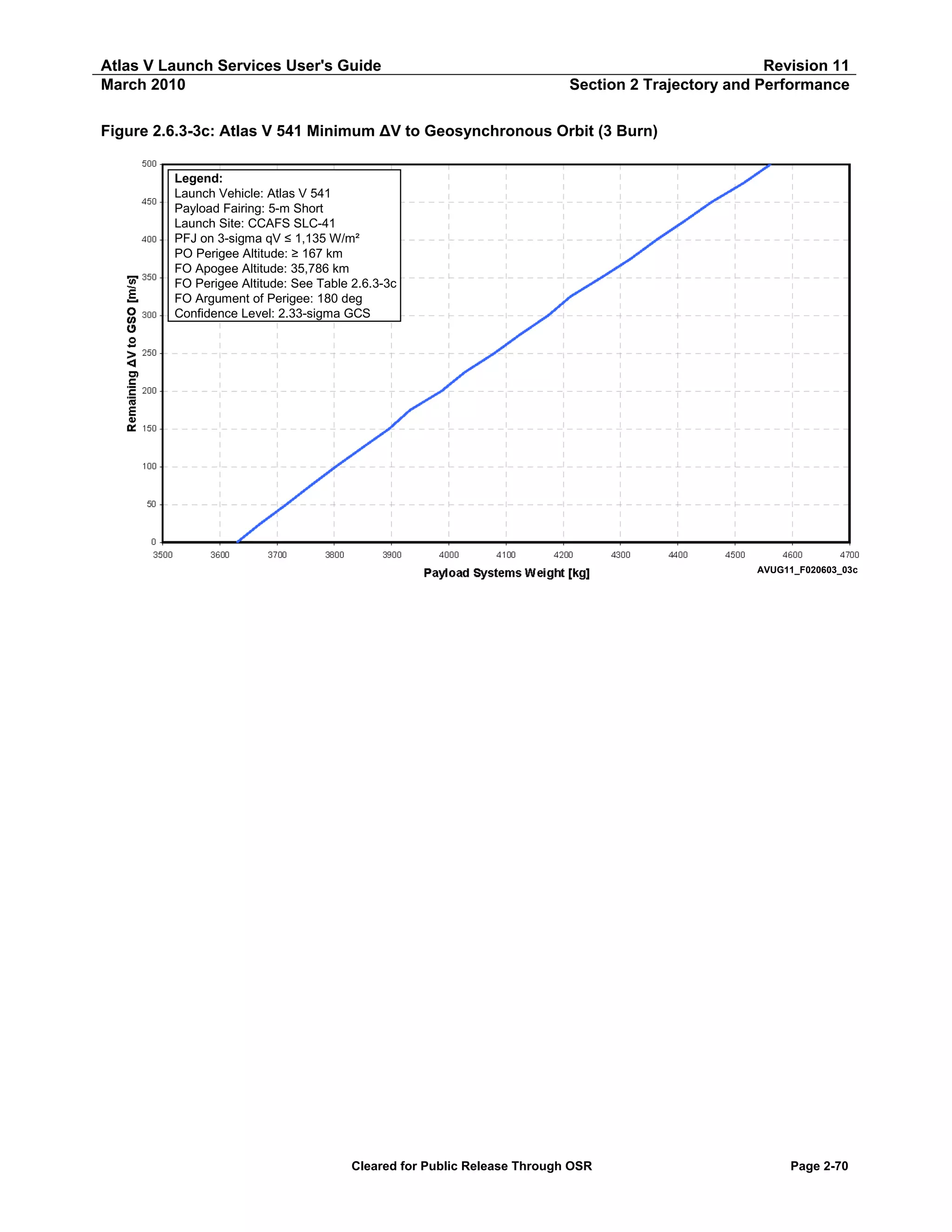
![Atlas V Launch Services User's Guide
March 2010
Revision 11
Section 2 Trajectory and Performance
Table 2.6.3-3c: Atlas V 541 Minimum ΔV to Geosynchronous Orbit (3 Burn) — Apogee Cap
ΔV to
GSO
[m/s]
500
475
450
425
400
375
350
325
300
275
250
225
200
175
150
125
100
75
50
25
0
Atlas V 541 GTO — ΔV to GSO at 35,786 km (19,323 nmi)
True
Payload Systems
Perigee
Inclination
Anomaly
Weight
[km]
[nmi]
[deg]
[deg]
[kg]
[lb]
17,791
9,607
4.4
-179.4
4,562
10,057
18,374
9,921
4.1
-179.1
4,514
9,952
19,080
10,302
3.9
-178.6
4,459
9,831
19,786
10,684
3.6
-179.2
4,412
9,726
20,562
11,103
3.5
-178.8
4,363
9,619
21,212
11,454
3.1
-179.0
4,317
9,518
21,991
11,874
2.9
-179.5
4,266
9,405
22,622
12,215
2.5
-176.2
4,212
9,287
23,521
12,700
2.4
-178.7
4,174
9,201
24,398
13,174
2.2
-178.9
4,125
9,093
25,265
13,642
2.0
-178.8
4,080
8,994
26,232
14,164
1.9
-179.0
4,028
8,879
27,096
14,631
1.6
-178.7
3,987
8,790
27,952
15,093
1.3
179.7
3,932
8,669
29,022
15,671
1.2
-179.0
3,895
8,588
30,056
16,229
1.0
-179.7
3,849
8,485
31,124
16,806
0.8
179.9
3,803
8,384
32,216
17,395
0.6
-178.6
3,759
8,287
33,360
18,013
0.4
-177.4
3,716
8,192
34,569
18,666
0.2
172.2
3,671
8,094
35,786
19,323
0.0
Undefined
3,630
8,003
Longitude
[deg]
95.2
95.3
95.2
95.5
95.4
95.5
95.5
95.5
95.5
95.5
95.5
95.3
95.5
95.2
95.5
95.5
95.6
95.6
95.6
95.5
95.6
Latitude
[deg]
0.0
0.1
0.1
0.1
0.1
0.1
0.0
0.2
0.1
0.0
0.0
0.0
0.0
0.0
0.0
0.0
0.0
0.0
0.0
0.0
0.0
Notes:
Launch Site: CCAFS SLC-41
Park Orbit Perigee Altitude ≥ 167 km (90 nmi)
Park Orbit Coast ≤ 2 Hours
Transfer Orbit Perigee Altitude ≥ 185 km (100 nmi)
Transfer Orbit Argument of Perigee = 180 deg
Confidence Level: 2.33 Sigma GCS
Apogee is at 1st SC Apogee, Perigee and Inclination are at SC Separation, True Anomaly is at Injection
Latitude and East Longitude are taken at SC Separation
Only oblate Earth effects were taken into account when propagating to 1st SC Apogee
Cleared for Public Release Through OSR
Page 2-71](https://image.slidesharecdn.com/atlasvusersguide2010-140220084057-phpapp02/75/Atlas-v-usersguide2010-101-2048.jpg)
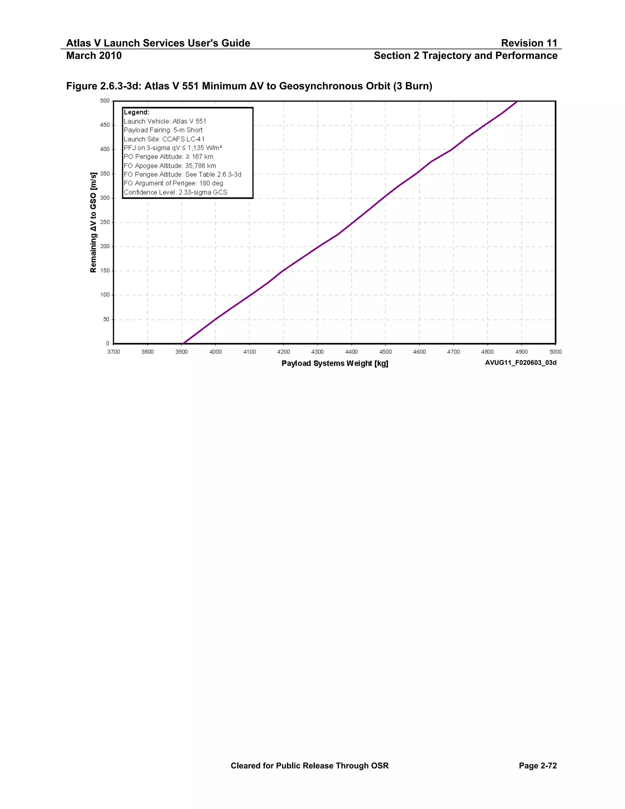
![Atlas V Launch Services User's Guide
March 2010
Revision 11
Section 2 Trajectory and Performance
Table 2.6.3-3d: Atlas V 551 Minimum ΔV to Geosynchronous Orbit (3 Burn) — Apogee Cap
ΔV to
GSO
[m/s]
500
475
450
425
400
375
350
325
300
275
250
225
200
175
150
125
100
75
50
25
0
Atlas V 551 GTO — ΔV to GSO at 35,786 km (19,323 nmi)
True
Payload Systems
Perigee
Inclination
Anomaly
Weight
[km]
[nmi]
[deg]
[deg]
[kg]
[lb]
17,281
9,331
3.6
-178.0
4,889
10,778
17,772
9,596
3.0
-178.0
4,842
10,676
19,133
10,331
3.9
-179.5
4,791
10,562
19,904
10,747
3.8
-179.5
4,740
10,450
20,573
11,109
3.5
-179.5
4,695
10,350
21,290
11,496
3.2
-179.0
4,634
10,217
21,967
11,861
2.9
-178.8
4,590
10,118
21,957
11,856
1.3
-178.0
4,538
10,005
22,981
12,409
1.6
-178.0
4,492
9,904
24,459
13,207
2.3
-178.6
4,449
9,807
25,203
13,608
1.9
-178.8
4,405
9,711
26,152
14,121
1.8
-178.8
4,360
9,612
27,078
14,621
1.6
-179.1
4,304
9,488
28,036
15,138
1.4
-178.4
4,250
9,370
28,982
15,649
1.1
-178.9
4,198
9,254
30,042
16,221
1.0
-178.4
4,153
9,156
31,127
16,807
0.8
-179.2
4,103
9,045
32,038
17,299
0.4
-178.0
4,051
8,930
33,347
18,006
0.4
-179.5
3,999
8,817
34,556
18,659
0.2
-178.8
3,952
8,712
35,786
19,323
0.0
Undefined
3,904
8,608
Longitude
[deg]
95.0
93.6
95.4
95.6
95.3
95.4
95.4
90.3
93.1
95.3
95.3
95.5
95.3
95.3
95.4
95.5
95.4
95.4
95.5
95.5
95.5
Latitude
[deg]
0.1
0.1
0.0
0.0
0.0
0.1
0.1
0.0
0.1
0.1
0.0
0.0
0.0
0.0
0.0
0.0
0.0
0.0
0.0
0.0
0.0
Notes:
Launch Site: CCAFS SLC-41
Park Orbit Perigee Altitude ≥ 167 km (90 nmi)
Park Orbit Coast ≤ 2 Hours
Transfer Orbit Perigee Altitude ≥ 185 km (100 nmi)
Transfer Orbit Argument of Perigee = 180 deg
Confidence Level: 2.33 Sigma GCS
Apogee is at 1st SC Apogee, Perigee and Inclination are at SC Separation, True Anomaly is at Injection
Latitude and East Longitude are taken at SC Separation
Only oblate Earth effects were taken into account when propagating to 1st SC Apogee
Cleared for Public Release Through OSR
Page 2-73](https://image.slidesharecdn.com/atlasvusersguide2010-140220084057-phpapp02/75/Atlas-v-usersguide2010-103-2048.jpg)
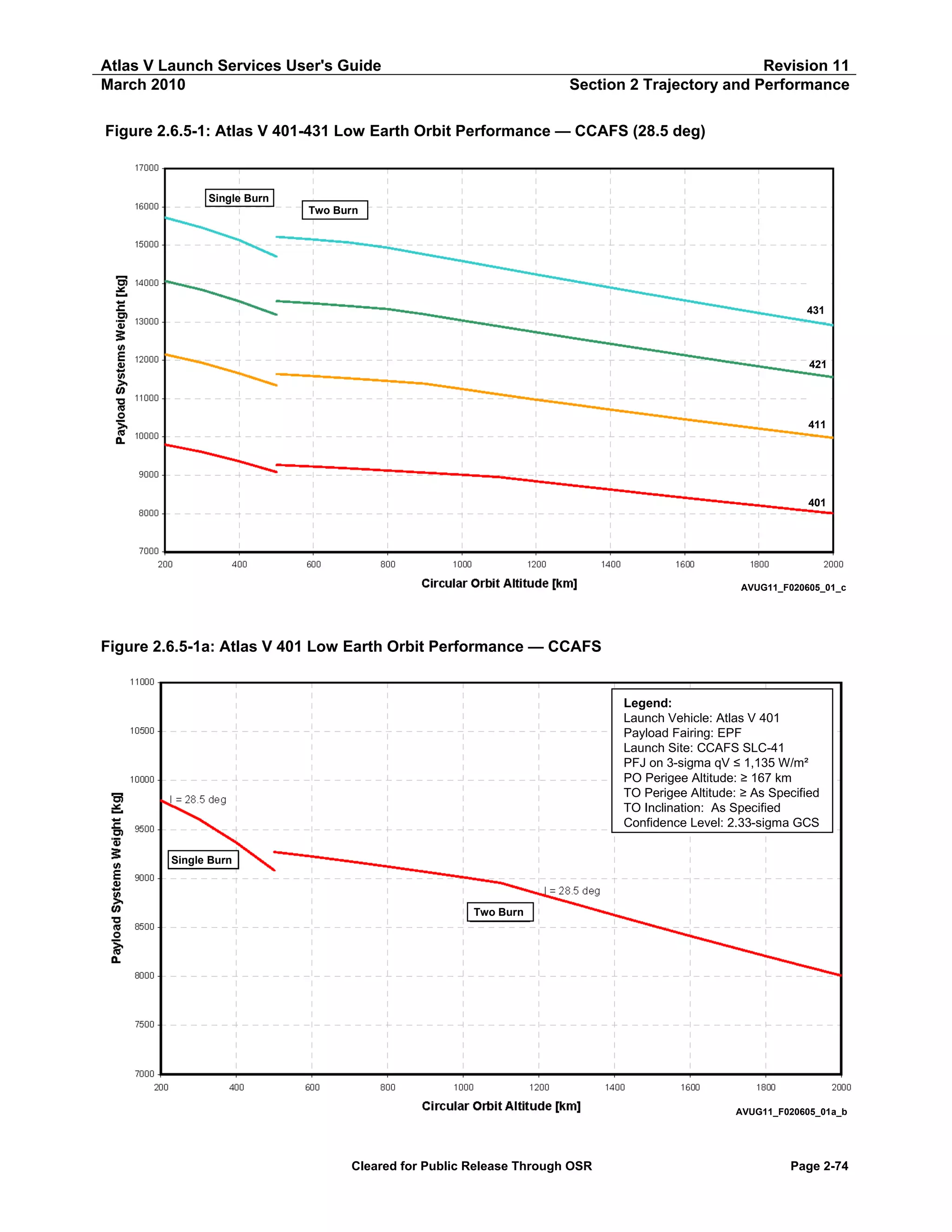
![Atlas V Launch Services User's Guide
March 2010
Revision 11
Section 2 Trajectory and Performance
Table 2.6.5-1a: Atlas V 401 Low Earth Orbit Performance — PSW vs Altitude
Atlas V 401 LEO — CCAFS
Circular Orbit
Altitude
[km]
[nmi]
2,000
1,900
1,800
1,700
1,600
1,500
1,400
1,300
1,200
1,100
1,000
900
800
700
600
500
1,080
1,026
972
918
864
810
756
702
648
594
540
486
432
378
324
270
500
400
300
200
270
216
162
108
Payload Systems Weight
I = 28.5 deg
[kg]
[lb]
Two Burn
8,008
8,107
8,207
8,309
8,413
8,518
8,625
8,733
8,842
8,952
9,011
9,067
9,122
9,174
9,224
9,269
17,655
17,873
18,094
18,318
18,546
18,779
19,016
19,253
19,494
19,736
19,867
19,990
20,110
20,226
20,335
20,435
9,083
9,365
9,607
9,797
20,024
20,645
21,180
21,598
Single Burn
Notes:
Launch Site: CCAFS SLC-41
Payload Fairing: EPF
PFJ at 3-sigma qV ≤ 1,135 W/m² (360 BTU/ft²-hr)
Park Orbit Perigee Altitude ≥ 167 km (90 nmi)
Confidence Level: 2.33 Sigma GCS
Cleared for Public Release Through OSR
Page 2-75](https://image.slidesharecdn.com/atlasvusersguide2010-140220084057-phpapp02/75/Atlas-v-usersguide2010-105-2048.jpg)
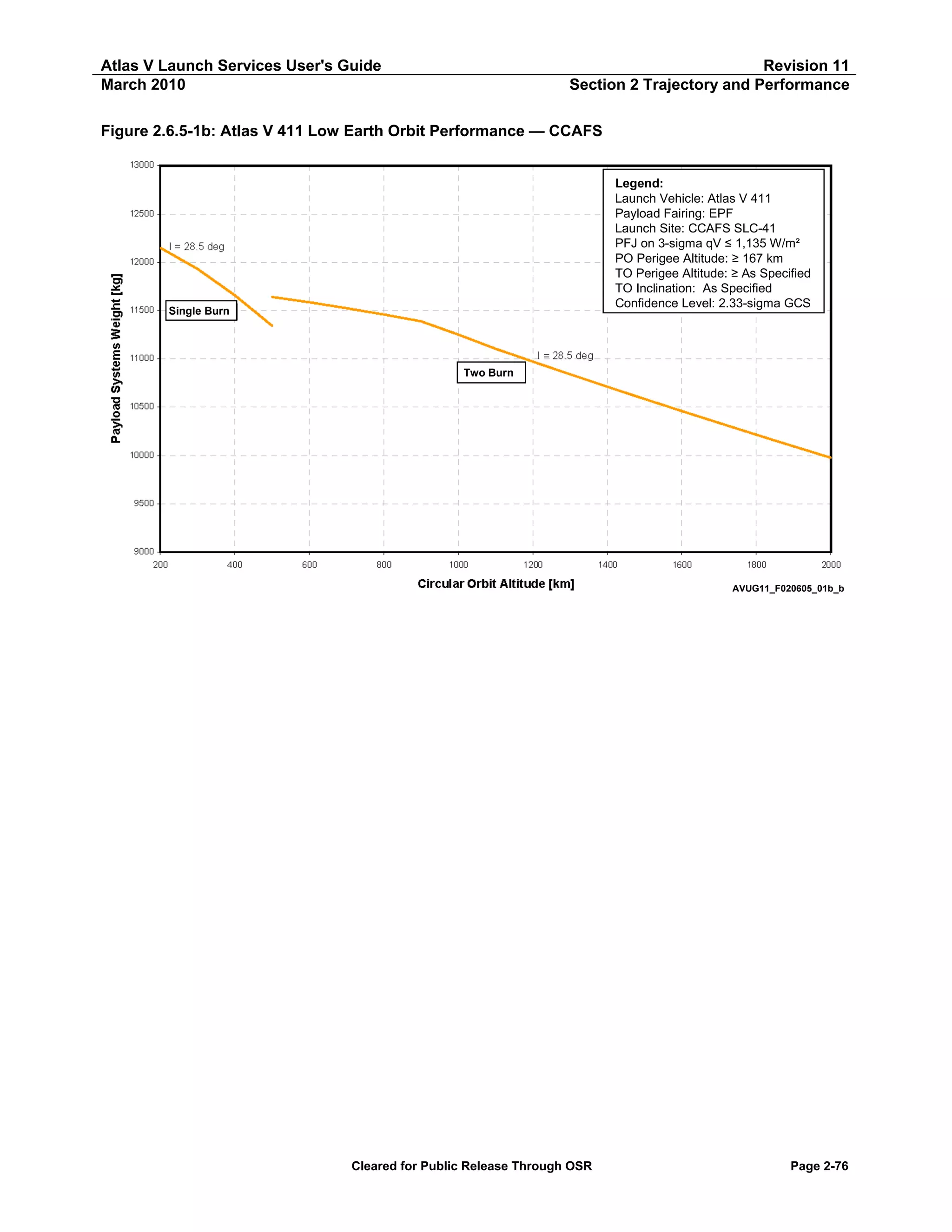
![Atlas V Launch Services User's Guide
March 2010
Revision 11
Section 2 Trajectory and Performance
Table 2.6.5-1b: Atlas V 411 Low Earth Orbit Performance — PSW vs Altitude
Atlas V 411 LEO — CCAFS
Circular Orbit
Altitude
[km]
[nmi]
2,000
1,900
1,800
1,700
1,600
1,500
1,400
1,300
1,200
1,100
1,000
900
800
700
600
500
1,080
1,026
972
918
864
810
756
702
648
594
540
486
432
378
324
270
500
400
300
200
270
216
162
108
Payload Systems Weight
I = 28.5 deg
[kg]
[lb]
Two Burn
9,976
10,094
10,214
10,335
10,459
10,584
10,711
10,840
10,971
11,104
11,251
11,388
11,459
11,524
11,585
11,641
21,994
22,254
22,518
22,786
23,057
23,333
23,614
23,899
24,187
24,480
24,804
25,106
25,262
25,406
25,540
25,663
11,342
11,656
11,931
12,150
25,005
25,698
26,303
26,787
Single Burn
Notes:
Launch Site: CCAFS SLC-41
Payload Fairing: EPF
PFJ at 3-sigma qV ≤ 1,135 W/m² (360 BTU/ft²-hr)
Park Orbit Perigee Altitude ≥ 167 km (90 nmi)
Confidence Level: 2.33 Sigma GCS
Cleared for Public Release Through OSR
Page 2-77](https://image.slidesharecdn.com/atlasvusersguide2010-140220084057-phpapp02/75/Atlas-v-usersguide2010-107-2048.jpg)
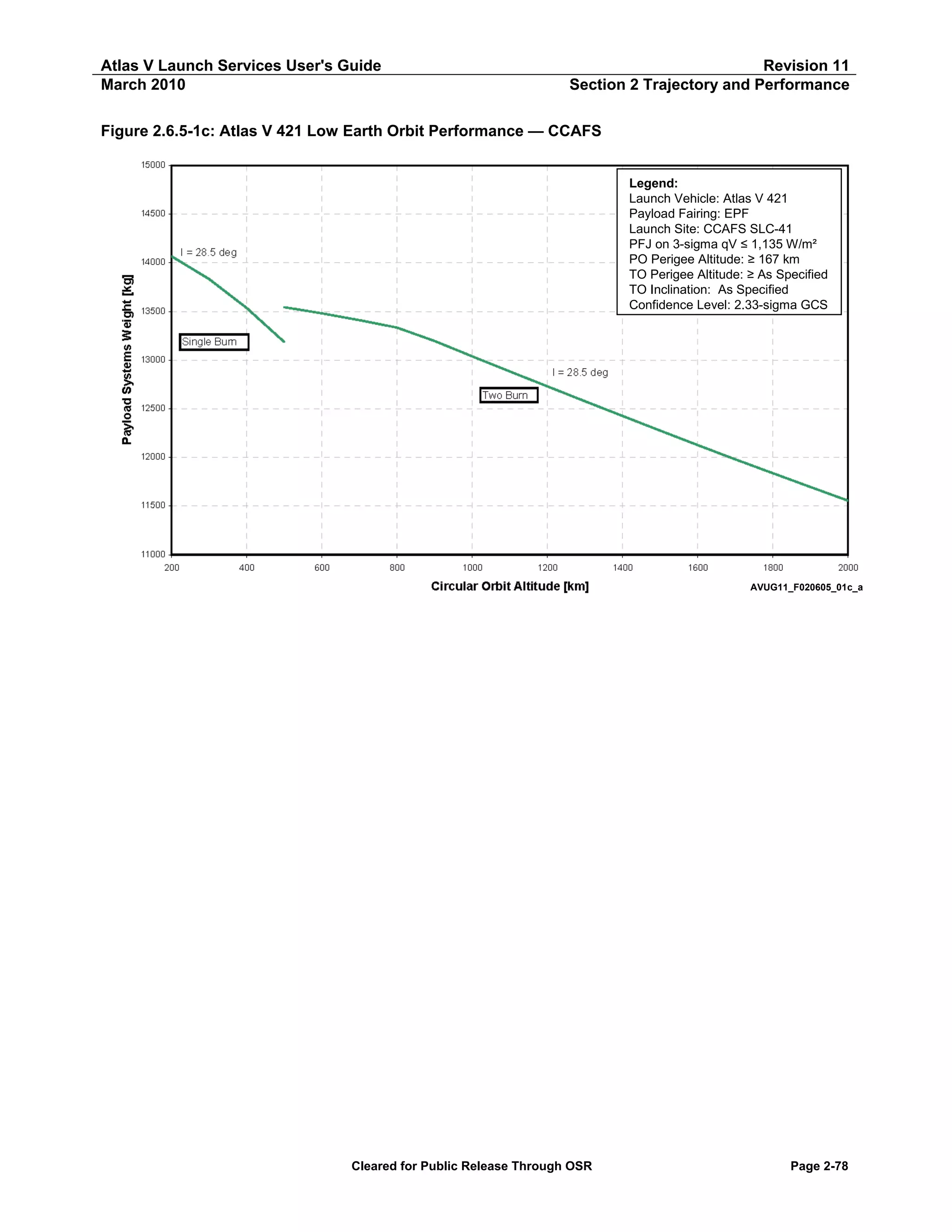
![Atlas V Launch Services User's Guide
March 2010
Revision 11
Section 2 Trajectory and Performance
Table 2.6.5-1c: Atlas V 421 Low Earth Orbit Performance — PSW vs Altitude
Atlas V 421 LEO — CCAFS
Circular Orbit
Altitude
[km]
[nmi]
2,000
1,900
1,800
1,700
1,600
1,500
1,400
1,300
1,200
1,100
1,000
900
800
700
600
500
1,080
1,026
972
918
864
810
756
702
648
594
540
486
432
378
324
270
500
400
300
200
270
216
162
108
Payload Systems Weight
I = 28.5 deg
[kg]
[lb]
Two Burn
11,555
11,695
11,837
11,981
12,127
12,275
12,425
12,576
12,729
12,883
13,038
13,196
13,333
13,409
13,480
13,544
25,474
25,782
26,095
26,413
26,735
27,062
27,393
27,726
28,063
28,403
28,744
29,093
29,394
29,562
29,719
29,859
13,185
13,535
13,832
14,067
29,069
29,839
30,495
31,012
Single Burn
Notes:
Launch Site: CCAFS SLC-41
Payload Fairing: EPF
PFJ at 3-sigma qV ≤ 1,135 W/m² (360 BTU/ft²-hr)
Park Orbit Perigee Altitude ≥ 167 km (90 nmi)
Confidence Level: 2.33 Sigma GCS
Cleared for Public Release Through OSR
Page 2-79](https://image.slidesharecdn.com/atlasvusersguide2010-140220084057-phpapp02/75/Atlas-v-usersguide2010-109-2048.jpg)
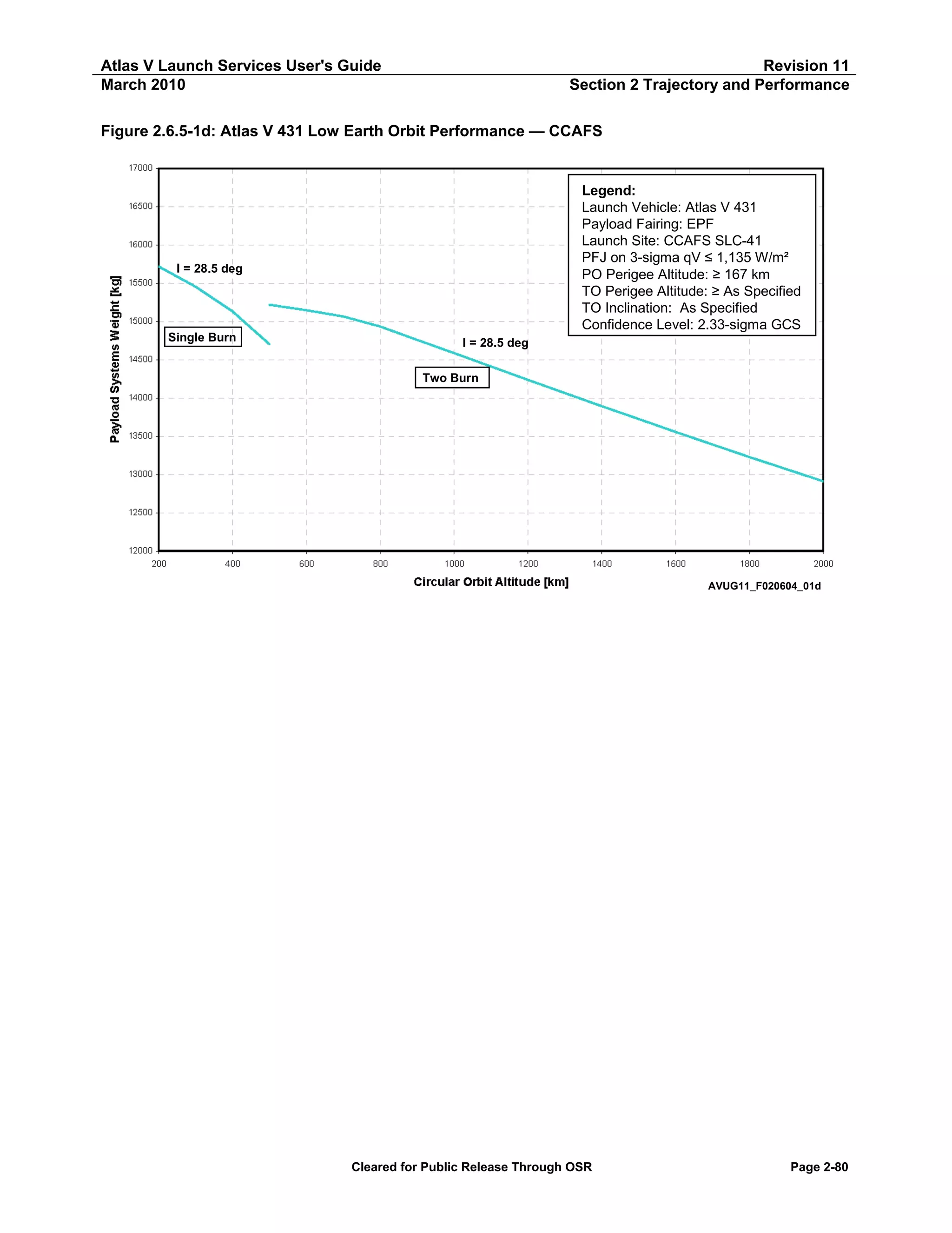
![Atlas V Launch Services User's Guide
March 2010
Revision 11
Section 2 Trajectory and Performance
Table 2.6.5-1d: Atlas V 431 Low Earth Orbit Performance — PSW vs Altitude
Atlas V 431 LEO — CCAFS
Circular Orbit
Altitude
[km]
[nmi]
2,000
1,900
1,800
1,700
1,600
1,500
1,400
1,300
1,200
1,100
1,000
900
800
700
600
500
1,080
1,026
972
918
864
810
756
702
648
594
540
486
432
378
324
270
500
400
300
200
270
216
162
108
Payload Systems Weight
I = 28.5 deg
[kg]
[lb]
Two Burn
12,911
13,069
13,229
13,391
13,556
13,724
13,893
14,064
14,237
14,411
14,585
14,759
14,933
15,066
15,146
15,218
28,463
28,812
29,164
29,522
29,886
30,255
30,629
31,007
31,386
31,770
32,154
32,538
32,922
33,214
33,392
33,550
14,700
15,130
15,453
15,718
32,409
33,356
34,067
34,653
Single Burn
Notes:
Launch Site: CCAFS SLC-41
Payload Fairing: EPF
PFJ at 3-sigma qV ≤ 1,135 W/m² (360 BTU/ft²-hr)
Park Orbit Perigee Altitude ≥ 167 km (90 nmi)
Confidence Level: 2.33 Sigma GCS
Cleared for Public Release Through OSR
Page 2-81](https://image.slidesharecdn.com/atlasvusersguide2010-140220084057-phpapp02/75/Atlas-v-usersguide2010-111-2048.jpg)
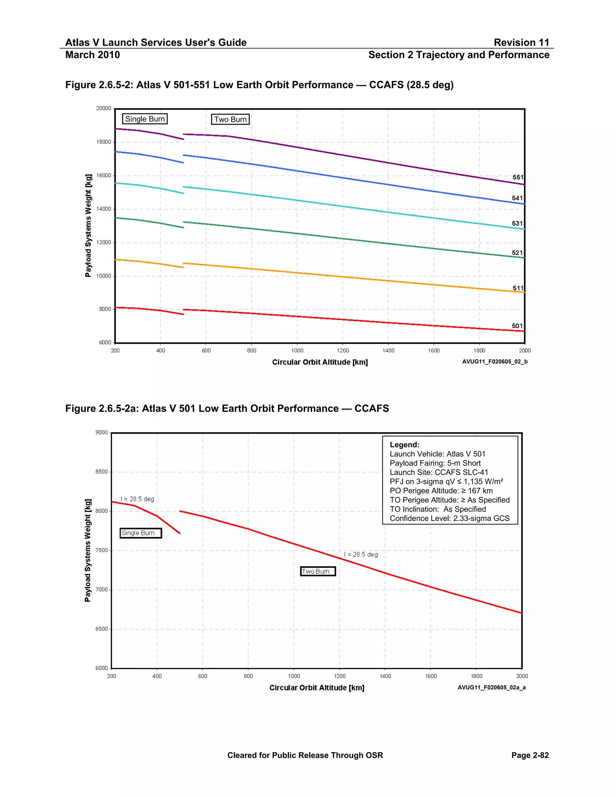
![Atlas V Launch Services User's Guide
March 2010
Revision 11
Section 2 Trajectory and Performance
Table 2.6.5-2a: Atlas V 501 Low Earth Orbit Performance — PSW vs Altitude
Atlas V 501 LEO — CCAFS
Circular Orbit
Altitude
[km]
[nmi]
2,000
1,900
1,800
1,700
1,600
1,500
1,400
1,300
1,200
1,100
1,000
900
800
700
600
500
1,080
1,026
972
918
864
810
756
702
648
594
540
486
432
378
324
270
500
400
300
200
270
216
162
108
Payload Systems Weight
I = 28.5 deg
[kg]
[lb]
Two Burn
6,704
6,786
6,869
6,953
7,039
7,126
7,214
7,311
7,403
7,496
7,588
7,680
7,777
7,856
7,939
8,005
14,780
14,961
15,144
15,330
15,518
15,710
15,905
16,118
16,322
16,525
16,729
16,930
17,144
17,320
17,502
17,647
7,721
7,941
8,075
8,123
17,021
17,507
17,802
17,908
Single Burn
Notes:
Launch Site: CCAFS SLC-41
Payload Fairing: 5-m Short
PFJ at 3-sigma qV ≤ 1,135 W/m² (360 BTU/ft²-hr)
Park Orbit Perigee Altitude ≥ 167 km (90 nmi)
Confidence Level: 2.33 Sigma GCS
Cleared for Public Release Through OSR
Page 2-83](https://image.slidesharecdn.com/atlasvusersguide2010-140220084057-phpapp02/75/Atlas-v-usersguide2010-113-2048.jpg)
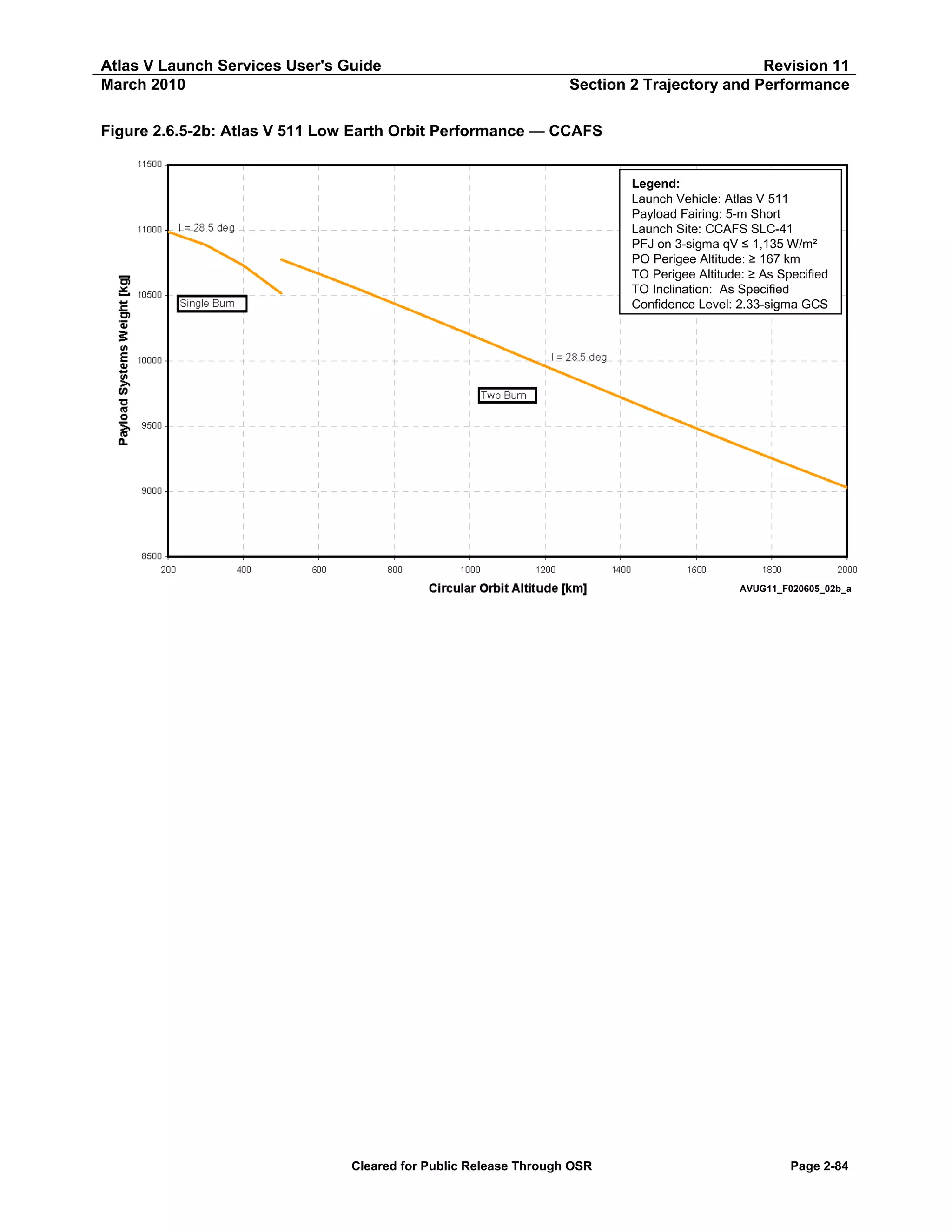
![Atlas V Launch Services User's Guide
March 2010
Revision 11
Section 2 Trajectory and Performance
Table 2.6.5-2b: Atlas V 511 Low Earth Orbit Performance — PSW vs Altitude
Atlas V 511 LEO — CCAFS
Circular Orbit
Altitude
[km]
[nmi]
2,000
1,900
1,800
1,700
1,600
1,500
1,400
1,300
1,200
1,100
1,000
900
800
700
600
500
1,080
1,026
972
918
864
810
756
702
648
594
540
486
432
378
324
270
500
400
300
200
270
216
162
108
Payload Systems Weight
I = 28.5 deg
[kg]
[lb]
Two Burn
9,030
9,141
9,253
9,367
9,483
9,600
9,719
9,839
9,959
10,080
10,200
10,320
10,438
10,553
10,666
10,774
19,907
20,151
20,399
20,651
20,906
21,165
21,427
21,691
21,956
22,222
22,488
22,752
23,011
23,266
23,514
23,752
10,516
10,728
10,887
10,986
23,184
23,652
24,001
24,221
Single Burn
Notes:
Launch Site: CCAFS SLC-41
Payload Fairing: 5-m Short
PFJ at 3-sigma qV ≤ 1,135 W/m² (360 BTU/ft²-hr)
Park Orbit Perigee Altitude ≥ 167 km (90 nmi)
Confidence Level: 2.33 Sigma GCS
Cleared for Public Release Through OSR
Page 2-85](https://image.slidesharecdn.com/atlasvusersguide2010-140220084057-phpapp02/75/Atlas-v-usersguide2010-115-2048.jpg)
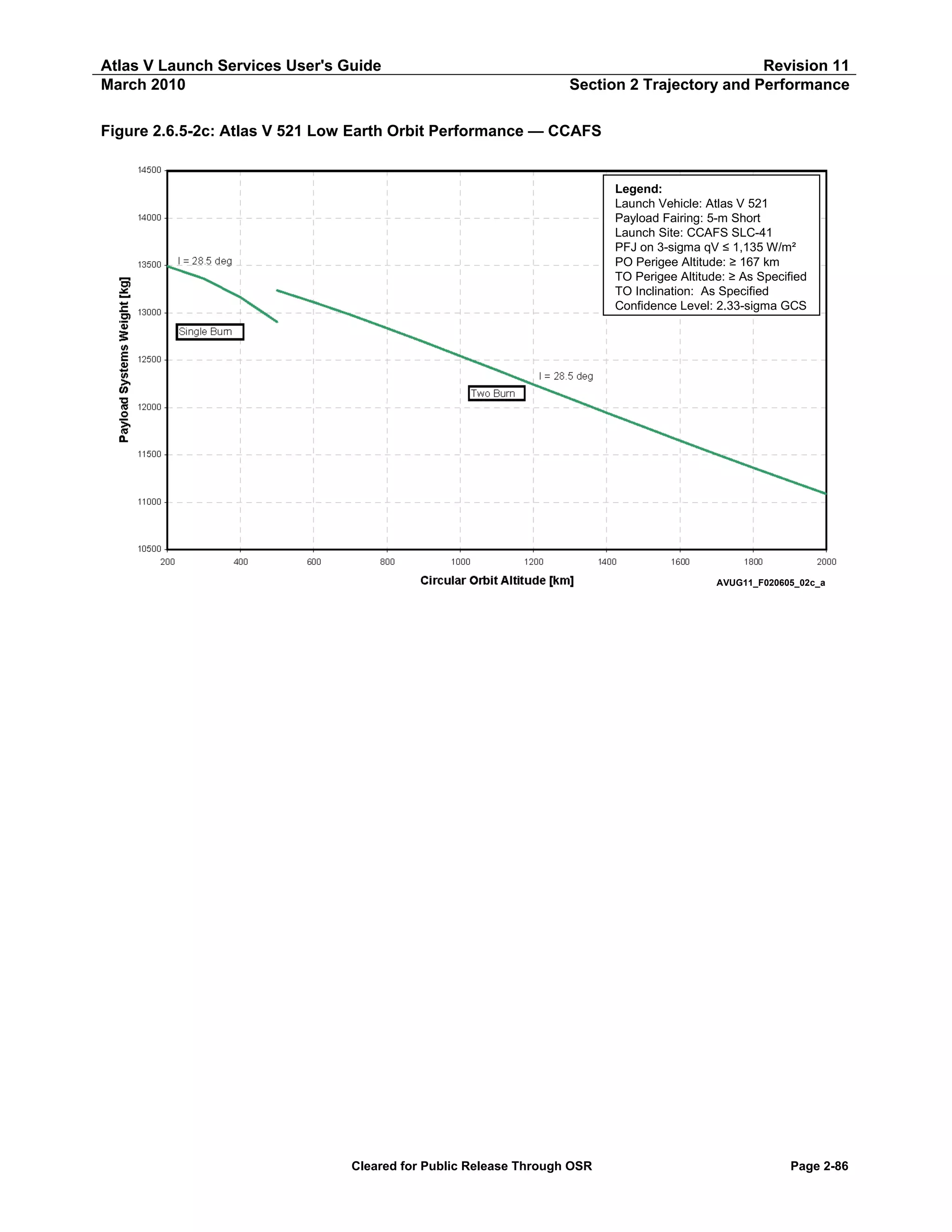
![Atlas V Launch Services User's Guide
March 2010
Revision 11
Section 2 Trajectory and Performance
Table 2.6.5-2c: Atlas V 521 Low Earth Orbit Performance — PSW vs Altitude
Atlas V 521 LEO — CCAFS
Circular Orbit
Altitude
[km]
[nmi]
2,000
1,900
1,800
1,700
1,600
1,500
1,400
1,300
1,200
1,100
1,000
900
800
700
600
500
1,080
1,026
972
918
864
810
756
702
648
594
540
486
432
378
324
270
500
400
300
200
270
216
162
108
Payload Systems Weight
I = 28.5 deg
[kg]
[lb]
Two Burn
11,087
11,225
11,364
11,506
11,650
11,796
11,943
12,093
12,243
12,393
12,544
12,692
12,838
12,978
13,112
13,235
24,443
24,746
25,053
25,366
25,683
26,006
26,330
26,660
26,991
27,322
27,654
27,981
28,302
28,612
28,907
29,179
12,903
13,163
13,360
13,490
28,446
29,019
29,453
29,741
Single Burn
Notes:
Launch Site: CCAFS SLC-41
Payload Fairing: 5-m Short
PFJ at 3-sigma qV ≤ 1,135 W/m² (360 BTU/ft²-hr)
Park Orbit Perigee Altitude ≥ 167 km (90 nmi)
Confidence Level: 2.33 Sigma GCS
Cleared for Public Release Through OSR
Page 2-87](https://image.slidesharecdn.com/atlasvusersguide2010-140220084057-phpapp02/75/Atlas-v-usersguide2010-117-2048.jpg)
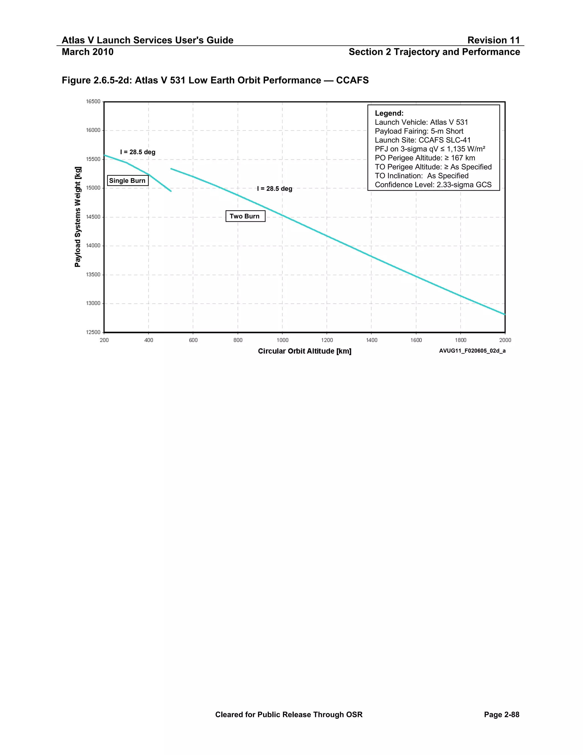
![Atlas V Launch Services User's Guide
March 2010
Revision 11
Section 2 Trajectory and Performance
Table 2.6.5-2d: Atlas V 531 Low Earth Orbit Performance — PSW vs Altitude
Atlas V 531 LEO — CCAFS
Circular Orbit
Altitude
[km]
[nmi]
2,000
1,900
1,800
1,700
1,600
1,500
1,400
1,300
1,200
1,100
1,000
900
800
700
600
500
1,080
1,026
972
918
864
810
756
702
648
594
540
486
432
378
324
270
500
400
300
200
270
216
162
108
Payload Systems Weight
I = 28.5 deg
[kg]
[lb]
Two Burn
12,809
12,970
13,135
13,302
13,472
13,645
13,820
13,996
14,173
14,353
14,531
14,708
14,881
15,046
15,201
15,340
28,238
28,594
28,958
29,326
29,701
30,082
30,467
30,857
31,247
31,643
32,036
32,427
32,806
33,171
33,513
33,819
14,950
15,237
15,445
15,575
32,959
33,593
34,051
34,337
Single Burn
Notes:
Launch Site: CCAFS SLC-41
Payload Fairing: 5-m Short
PFJ at 3-sigma qV ≤ 1,135 W/m² (360 BTU/ft²-hr)
Park Orbit Perigee Altitude ≥ 167 km (90 nmi)
Confidence Level: 2.33 Sigma GCS
Cleared for Public Release Through OSR
Page 2-89](https://image.slidesharecdn.com/atlasvusersguide2010-140220084057-phpapp02/75/Atlas-v-usersguide2010-119-2048.jpg)
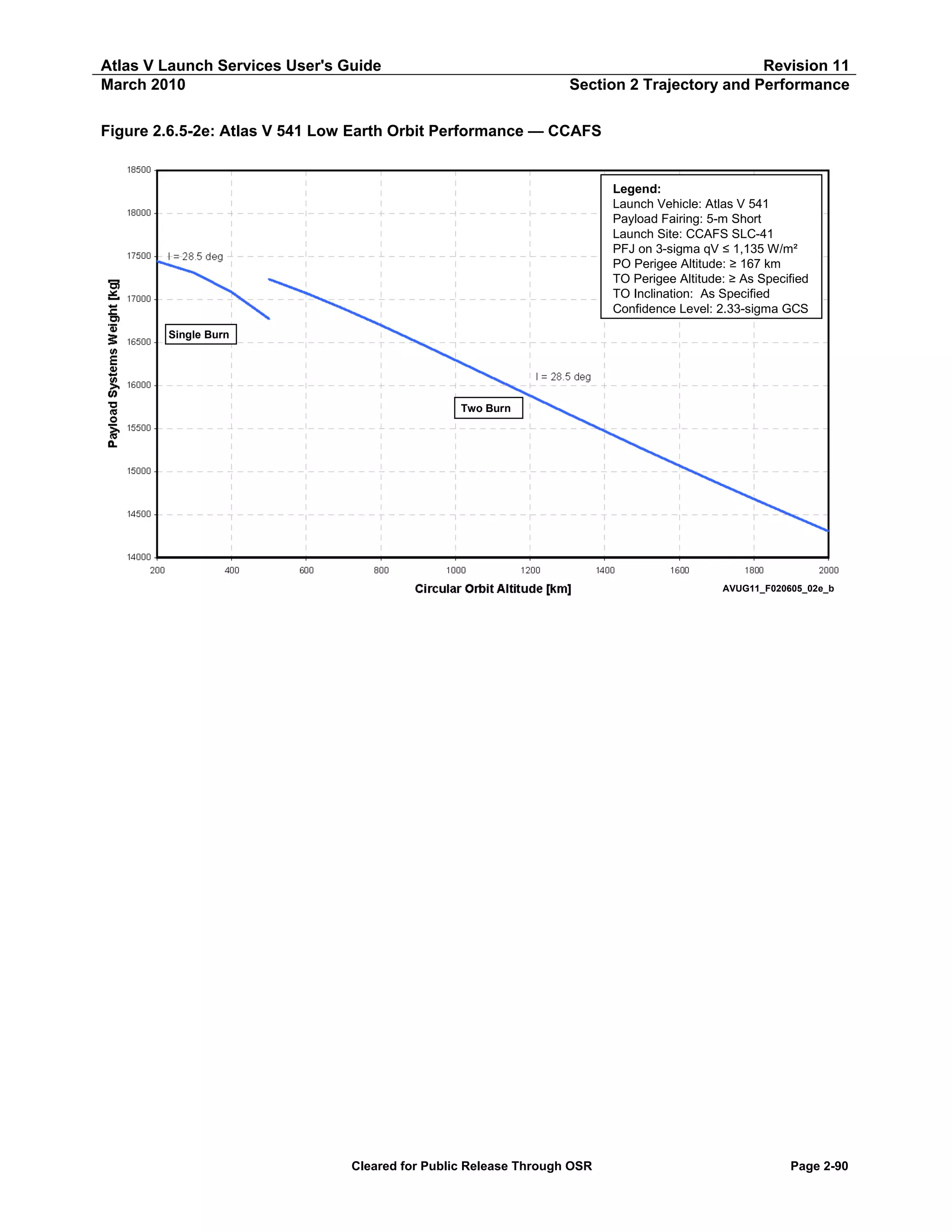
![Atlas V Launch Services User's Guide
March 2010
Revision 11
Section 2 Trajectory and Performance
Table 2.6.5-2e: Atlas V 541 Low Earth Orbit Performance — PSW vs Altitude
Atlas V 541 LEO — CCAFS
Circular Orbit
Altitude
[km]
[nmi]
2,000
1,900
1,800
1,700
1,600
1,500
1,400
1,300
1,200
1,100
1,000
900
800
700
600
500
1,080
1,026
972
918
864
810
756
702
648
594
540
486
432
378
324
270
500
400
300
200
270
216
162
108
Payload Systems Weight
I = 28.5 deg
[kg]
[lb]
Two Burn
14,304
14,490
14,678
14,871
15,067
15,266
15,469
15,673
15,880
16,087
16,294
16,499
16,700
16,892
17,073
17,234
31,536
31,944
32,361
32,785
33,217
33,656
34,103
34,553
35,009
35,466
35,922
36,374
36,816
37,240
37,640
37,995
16,773
17,083
17,308
17,443
36,978
37,662
38,158
38,456
Single Burn
Notes:
Launch Site: CCAFS SLC-41
Payload Fairing: 5-m Short
PFJ at 3-sigma qV ≤ 1,135 W/m² (360 BTU/ft²-hr)
Park Orbit Perigee Altitude ≥ 167 km (90 nmi)
Confidence Level: 2.33 Sigma GCS
Cleared for Public Release Through OSR
Page 2-91](https://image.slidesharecdn.com/atlasvusersguide2010-140220084057-phpapp02/75/Atlas-v-usersguide2010-121-2048.jpg)
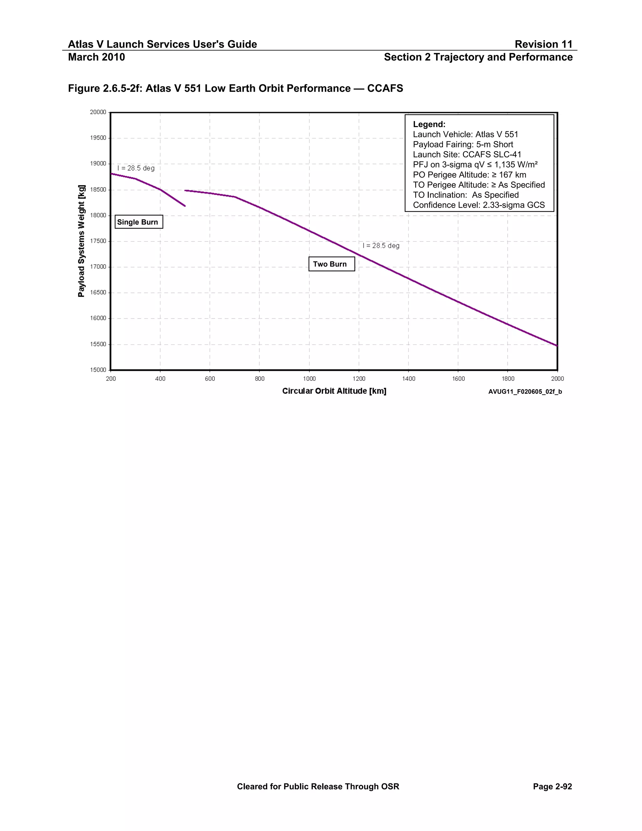
![Atlas V Launch Services User's Guide
March 2010
Revision 11
Section 2 Trajectory and Performance
Table 2.6.5-2f: Atlas V 551 Low Earth Orbit Performance — PSW vs Altitude
Atlas V 551 LEO — CCAFS
Circular Orbit
Altitude
[km]
[nmi]
2,000
1,900
1,800
1,700
1,600
1,500
1,400
1,300
1,200
1,100
1,000
900
800
700
600
500
1,080
1,026
972
918
864
810
756
702
648
594
540
486
432
378
324
270
500
400
300
200
270
216
162
108
Payload Systems Weight
I = 28.5 deg
[kg]
[lb]
Two Burn
15,469
15,675
15,888
16,104
16,324
16,548
16,775
17,005
17,237
17,470
17,703
17,934
18,159
18,363
18,434
18,487
34,103
34,557
35,027
35,503
35,988
36,482
36,983
37,490
38,002
38,515
39,028
39,537
40,034
40,483
40,640
40,756
18,182
18,505
18,713
18,814
40,083
40,796
41,256
41,478
Single Burn
Notes:
Launch Site: CCAFS SLC-41
Payload Fairing: 5-m Short
PFJ at 3-sigma qV ≤ 1,135 W/m² (360 BTU/ft²-hr)
Park Orbit Perigee Altitude ≥ 167 km (90 nmi)
Confidence Level: 2.33 Sigma GCS
Cleared for Public Release Through OSR
Page 2-93](https://image.slidesharecdn.com/atlasvusersguide2010-140220084057-phpapp02/75/Atlas-v-usersguide2010-123-2048.jpg)
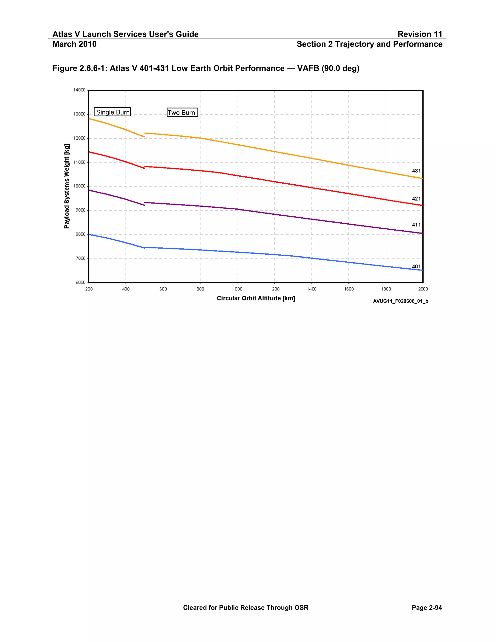
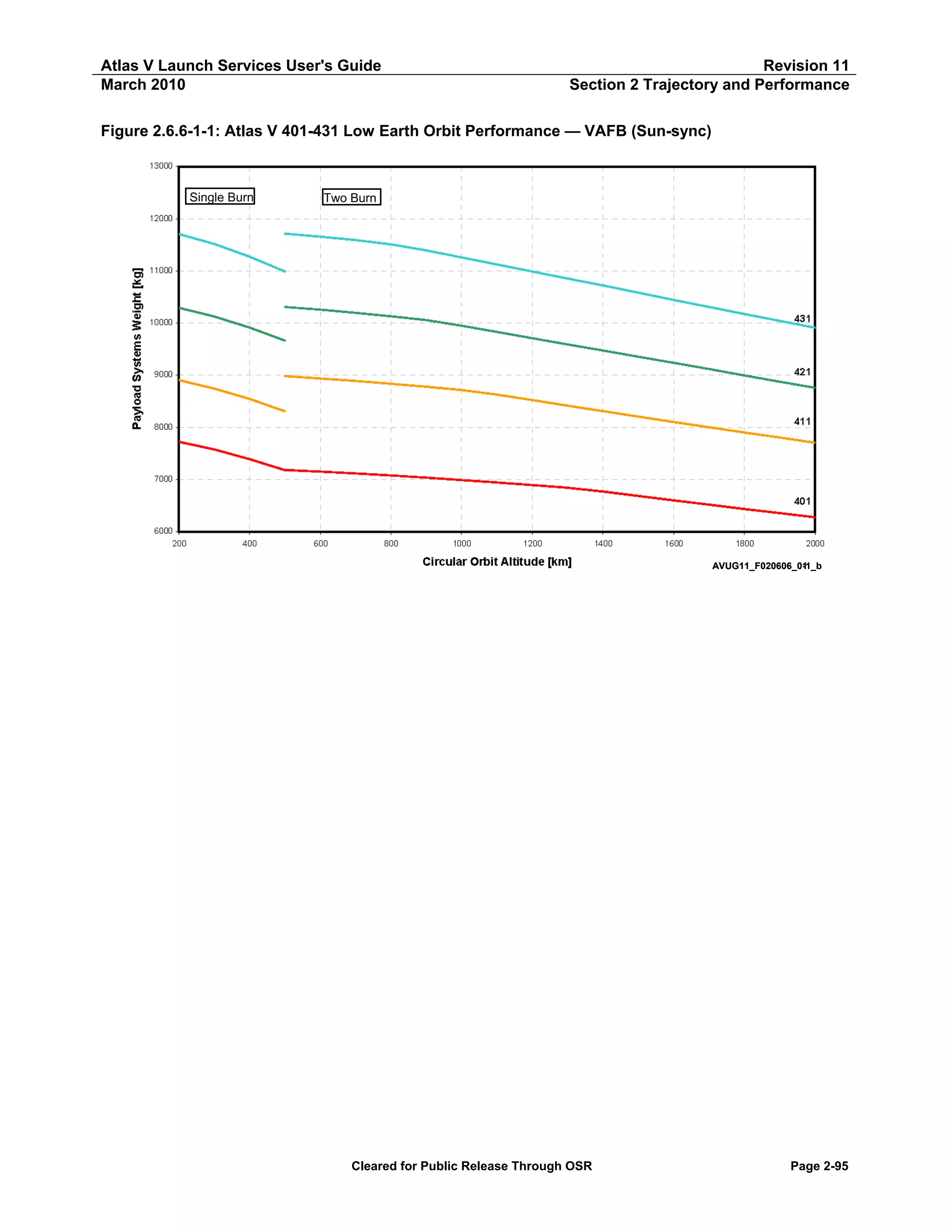
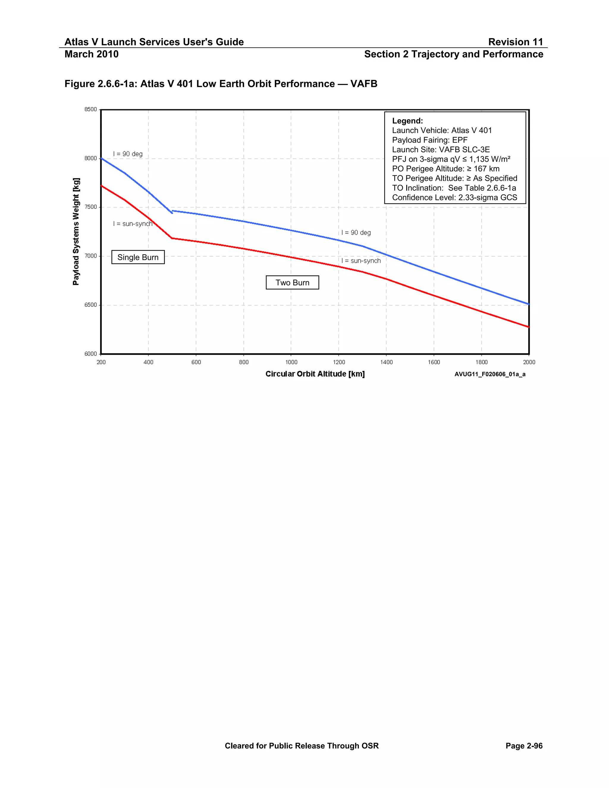
![Atlas V Launch Services User's Guide
March 2010
Revision 11
Section 2 Trajectory and Performance
Table 2.6.6-1a: Atlas V 401 Low Earth Orbit Performance — PSW vs Altitude (VAFB)
Atlas V 401 LEO — VAFB
Payload Systems Weight
I = 90 deg
Sun-Synch
[kg]
[lb]
[kg]
[lb]
Two Burn
6,509
14,351
6,276
13,836
6,591
14,530
6,355
14,009
6,673
14,712
6,435
14,186
6,757
14,897
6,516
14,365
6,842
15,085
6,599
14,547
6,929
15,276
6,682
14,732
7,017
15,469
6,767
14,920
7,104
15,662
6,840
15,081
7,164
15,794
6,894
15,198
7,216
15,909
6,943
15,307
7,266
16,018
6,990
15,411
7,312
16,120
7,035
15,510
7,356
16,218
7,077
15,603
7,397
16,308
7,117
15,689
7,434
16,390
7,152
15,768
7,467
16,461
7,184
15,837
Single Burn
7,438
16,399
7,180
15,828
7,658
16,883
7,392
16,297
7,851
17,308
7,575
16,700
8,005
17,647
7,724
17,028
Circular Orbit
Altitude
[km]
[nmi]
2,000
1,900
1,800
1,700
1,600
1,500
1,400
1,300
1,200
1,100
1,000
900
800
700
600
500
1,080
1,026
972
918
864
810
756
702
648
594
540
486
432
378
324
270
500
400
300
200
270
216
162
108
Notes:
Launch Site: VAFB SLC-3E
Payload Fairing: EPF
PFJ at 3-sigma qV ≤ 1,135 W/m² (360 BTU/ft²-hr)
Park Orbit Perigee Altitude ≥ 167 km (90 nmi)
Confidence Level: 2.33 Sigma GCS
Cleared for Public Release Through OSR
Page 2-97](https://image.slidesharecdn.com/atlasvusersguide2010-140220084057-phpapp02/75/Atlas-v-usersguide2010-127-2048.jpg)
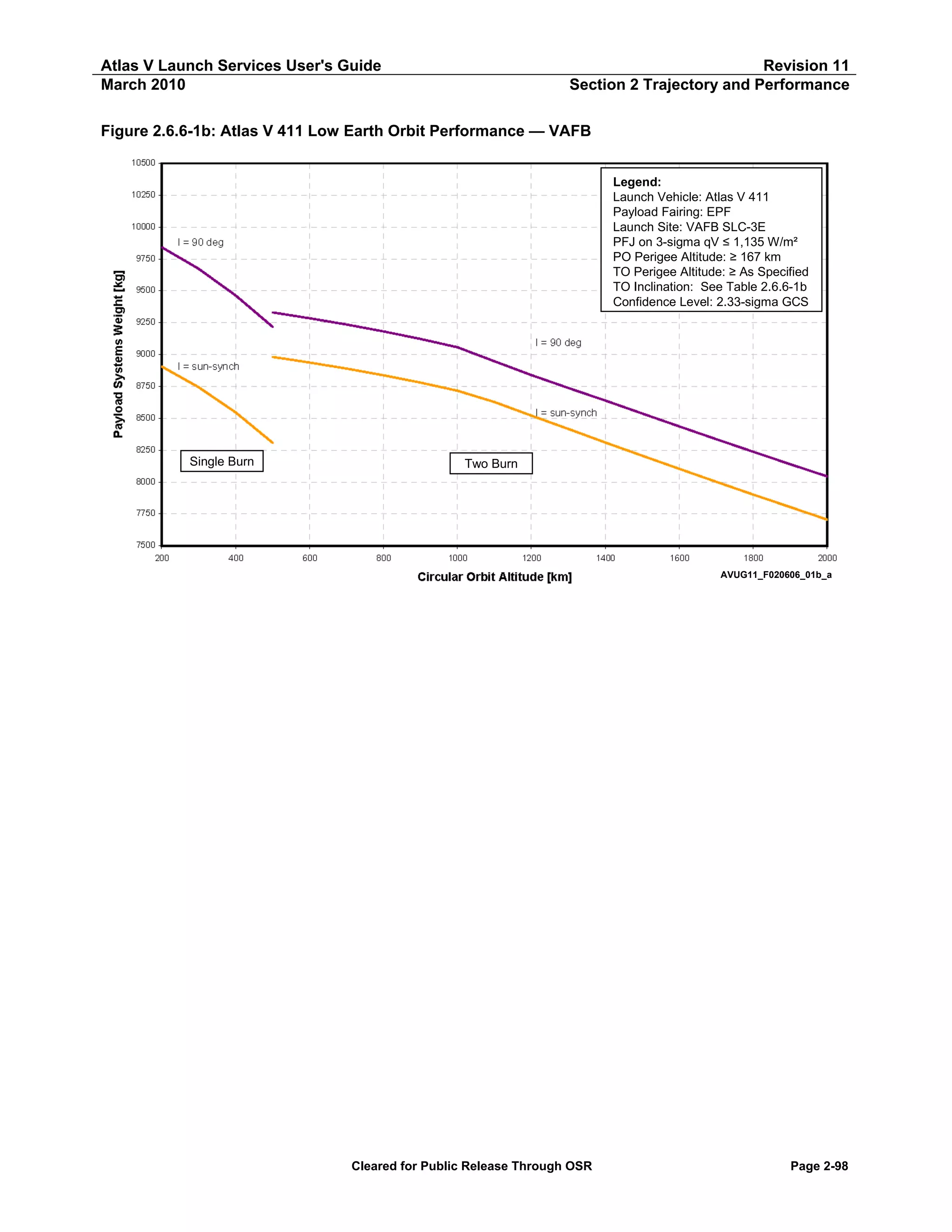
![Atlas V Launch Services User's Guide
March 2010
Revision 11
Section 2 Trajectory and Performance
Table 2.6.6-1b: Atlas V 411 Low Earth Orbit Performance — PSW vs Altitude (VAFB)
Atlas V 411 LEO — VAFB
Payload Systems Weight
I = 90 deg
Sun-Synch
[kg]
[lb]
[kg]
[lb]
Two Burn
8,043
17,732
7,704
16,985
8,139
17,944
7,803
17,202
8,237
18,159
7,902
17,420
8,336
18,377
8,001
17,640
8,436
18,597
8,103
17,864
8,537
18,820
8,206
18,091
8,639
19,046
8,310
18,320
8,738
19,263
8,415
18,552
8,838
19,485
8,521
18,786
8,947
19,725
8,627
19,020
9,056
19,965
8,716
19,215
9,122
20,111
8,779
19,354
9,181
20,241
8,836
19,481
9,235
20,360
8,889
19,597
9,285
20,470
8,938
19,704
9,330
20,569
8,982
19,801
Single Burn
9,218
20,322
8,308
18,316
9,463
20,863
8,545
18,838
9,672
21,324
8,744
19,278
9,842
21,698
8,905
19,633
Circular Orbit
Altitude
[km]
[nmi]
2,000
1,900
1,800
1,700
1,600
1,500
1,400
1,300
1,200
1,100
1,000
900
800
700
600
500
1,080
1,026
972
918
864
810
756
702
648
594
540
486
432
378
324
270
500
400
300
200
270
216
162
108
Notes:
Launch Site: VAFB SLC-3E
Payload Fairing: EPF
PFJ at 3-sigma qV ≤ 1,135 W/m² (360 BTU/ft²-hr)
Park Orbit Perigee Altitude ≥ 167 km (90 nmi)
Confidence Level: 2.33 Sigma GCS
Cleared for Public Release Through OSR
Page 2-99](https://image.slidesharecdn.com/atlasvusersguide2010-140220084057-phpapp02/75/Atlas-v-usersguide2010-129-2048.jpg)

![Atlas V Launch Services User's Guide
March 2010
Revision 11
Section 2 Trajectory and Performance
Table 2.6.6-1c: Atlas V 421 Low Earth Orbit Performance — PSW vs Altitude (VAFB)
Atlas V 421 LEO — VAFB
Payload Systems Weight
I = 90 deg
Sun-Synch
[kg]
[lb]
[kg]
[lb]
Two Burn
9,203
20,290
8,759
19,311
9,324
20,557
8,876
19,568
9,448
20,829
8,995
19,830
9,573
21,105
9,116
20,097
9,700
21,384
9,237
20,365
9,826
21,663
9,354
20,622
9,949
21,934
9,471
20,880
10,074
22,208
9,589
21,141
10,199
22,484
9,709
21,404
10,324
22,761
9,829
21,669
10,450
23,039
9,949
21,933
10,574
23,312
10,056
22,170
10,653
23,486
10,132
22,336
10,719
23,632
10,197
22,479
10,778
23,762
10,255
22,610
10,831
23,878
10,309
22,727
Single Burn
10,752
23,705
9,663
21,302
11,024
24,303
9,915
21,859
11,253
24,808
10,127
22,326
11,437
25,215
10,290
22,687
Circular Orbit
Altitude
[km]
[nmi]
2,000
1,900
1,800
1,700
1,600
1,500
1,400
1,300
1,200
1,100
1,000
900
800
700
600
500
1,080
1,026
972
918
864
810
756
702
648
594
540
486
432
378
324
270
500
400
300
200
270
216
162
108
Notes:
Launch Site: VAFB SLC-3E
Payload Fairing: EPF
PFJ at 3-sigma qV ≤ 1,135 W/m² (360 BTU/ft²-hr)
Park Orbit Perigee Altitude ≥ 167 km (90 nmi)
Confidence Level: 2.33 Sigma GCS
Cleared for Public Release Through OSR
Page 2-101](https://image.slidesharecdn.com/atlasvusersguide2010-140220084057-phpapp02/75/Atlas-v-usersguide2010-131-2048.jpg)
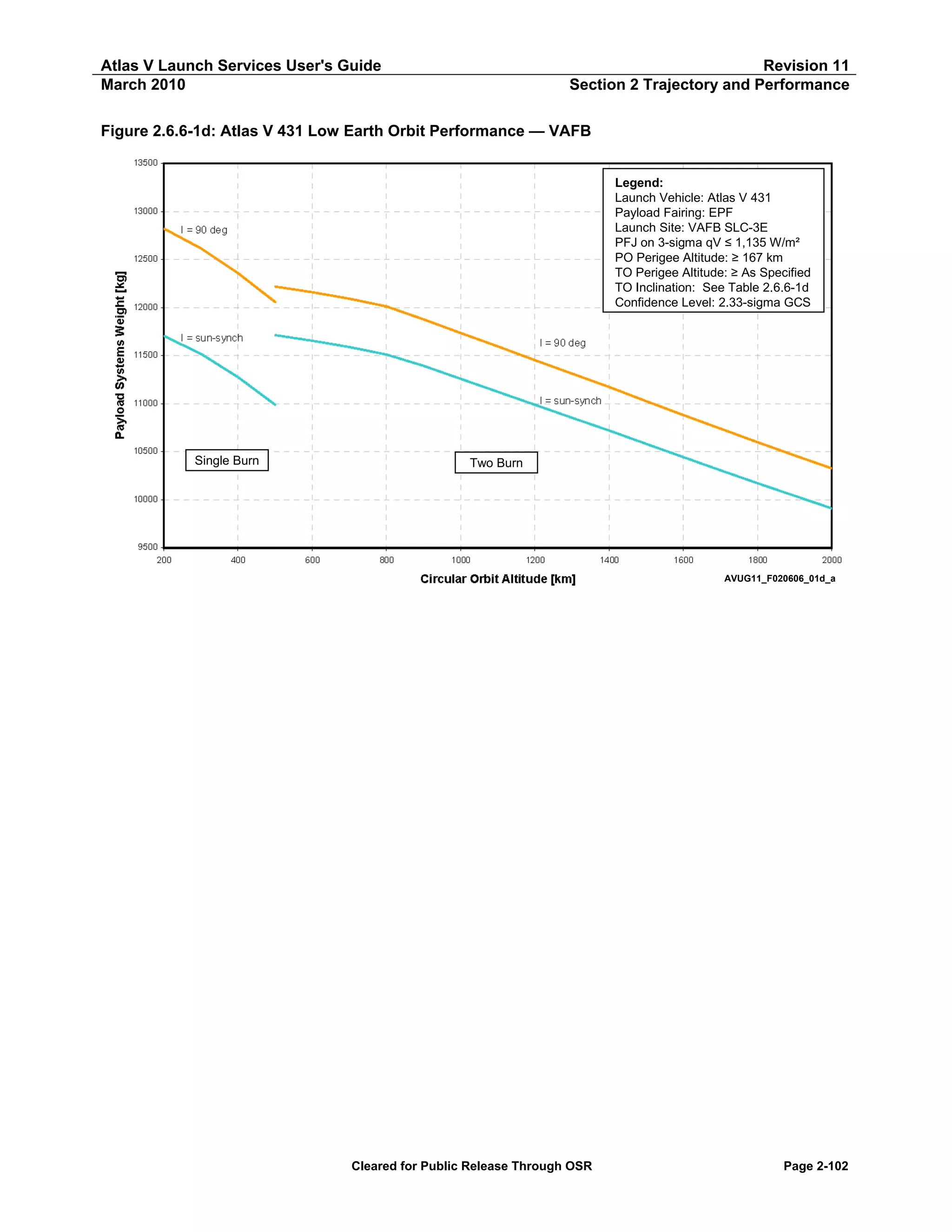
![Atlas V Launch Services User's Guide
March 2010
Revision 11
Section 2 Trajectory and Performance
Table 2.6.6-1d: Atlas V 431 Low Earth Orbit Performance — PSW vs Altitude (VAFB)
Atlas V 431 LEO — VAFB
Payload Systems Weight
I = 90 deg
Sun-Synch
[kg]
[lb]
[kg]
[lb]
Two Burn
10,325
22,763
9,909
21,847
10,461
23,062
10,039
22,133
10,598
23,366
10,172
22,425
10,739
23,675
10,306
22,721
10,881
23,988
10,443
23,022
11,025
24,307
10,581
23,327
11,171
24,629
10,719
23,631
11,312
24,939
10,853
23,926
11,452
25,247
10,987
24,222
11,594
25,560
11,122
24,520
11,735
25,871
11,257
24,818
11,876
26,183
11,391
25,114
12,011
26,480
11,511
25,376
12,092
26,658
11,588
25,547
12,159
26,807
11,654
25,694
12,218
26,937
11,713
25,823
Single Burn
12,056
26,579
10,987
24,222
12,358
27,244
11,274
24,854
12,613
27,808
11,516
25,388
12,820
28,263
11,704
25,803
Circular Orbit
Altitude
[km]
[nmi]
2,000
1,900
1,800
1,700
1,600
1,500
1,400
1,300
1,200
1,100
1,000
900
800
700
600
500
1,080
1,026
972
918
864
810
756
702
648
594
540
486
432
378
324
270
500
400
300
200
270
216
162
108
Notes:
Launch Site: VAFB SLC-3E
Payload Fairing: EPF
PFJ at 3-sigma qV ≤ 1,135 W/m² (360 BTU/ft²-hr)
Park Orbit Perigee Altitude ≥ 167 km (90 nmi)
Confidence Level: 2.33 Sigma GCS
Cleared for Public Release Through OSR
Page 2-103](https://image.slidesharecdn.com/atlasvusersguide2010-140220084057-phpapp02/75/Atlas-v-usersguide2010-133-2048.jpg)
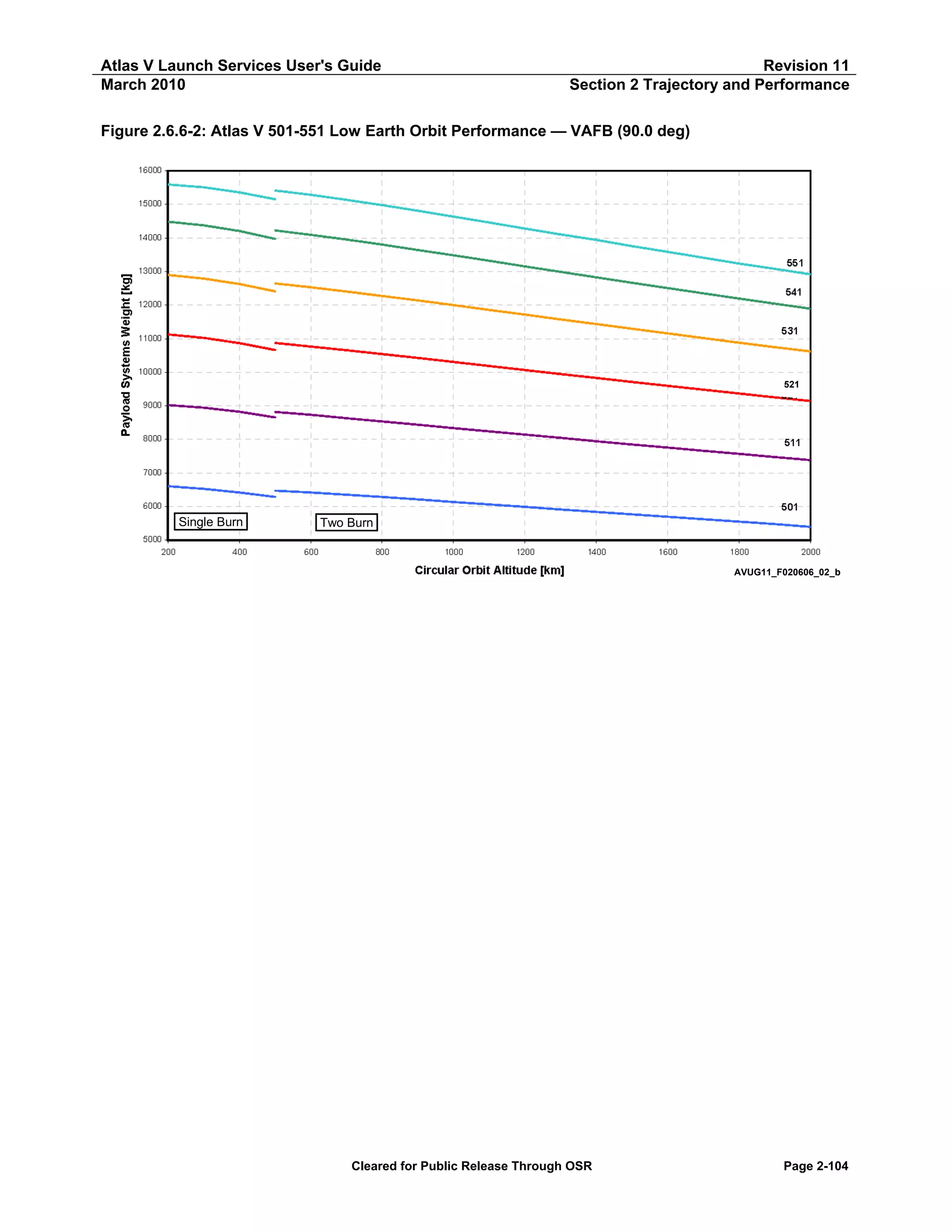
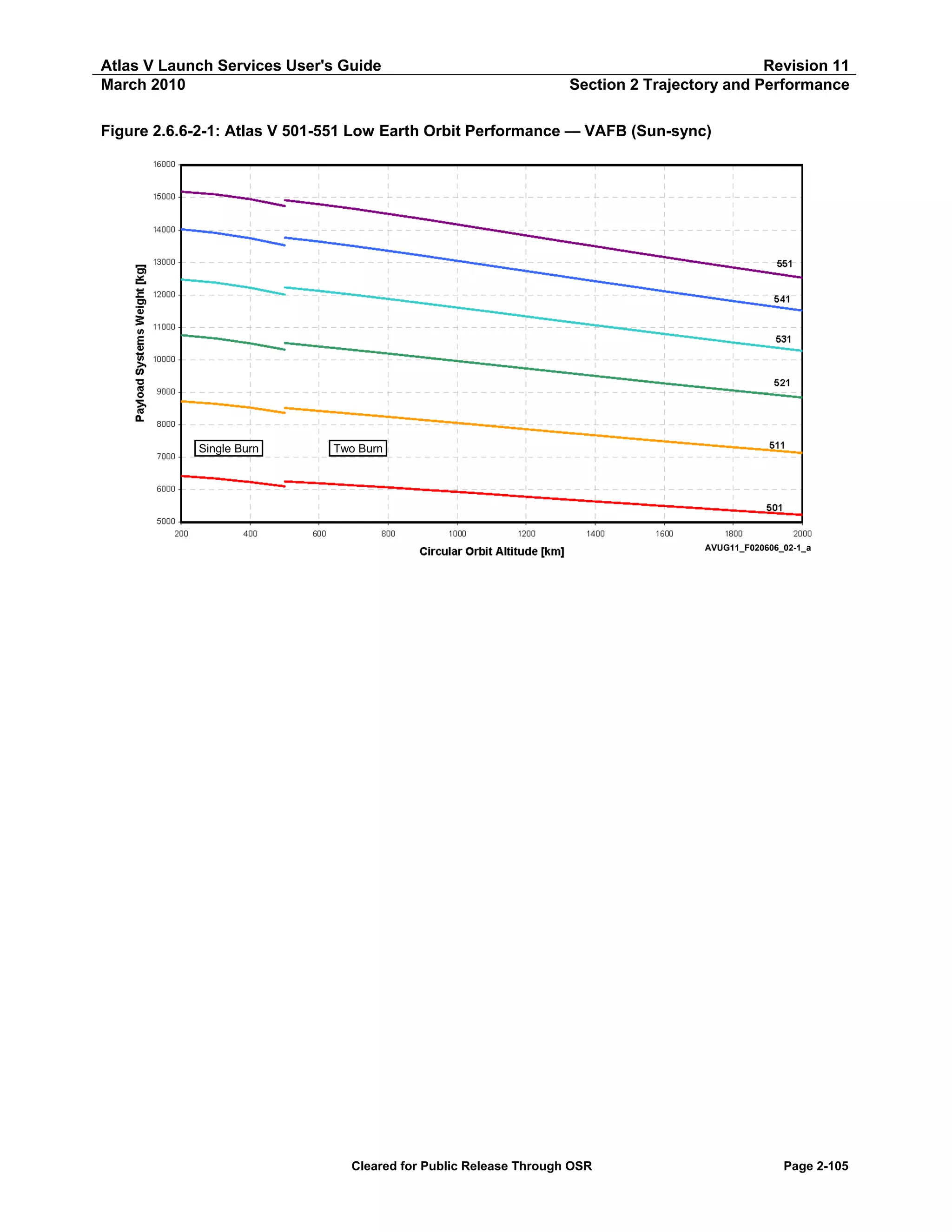
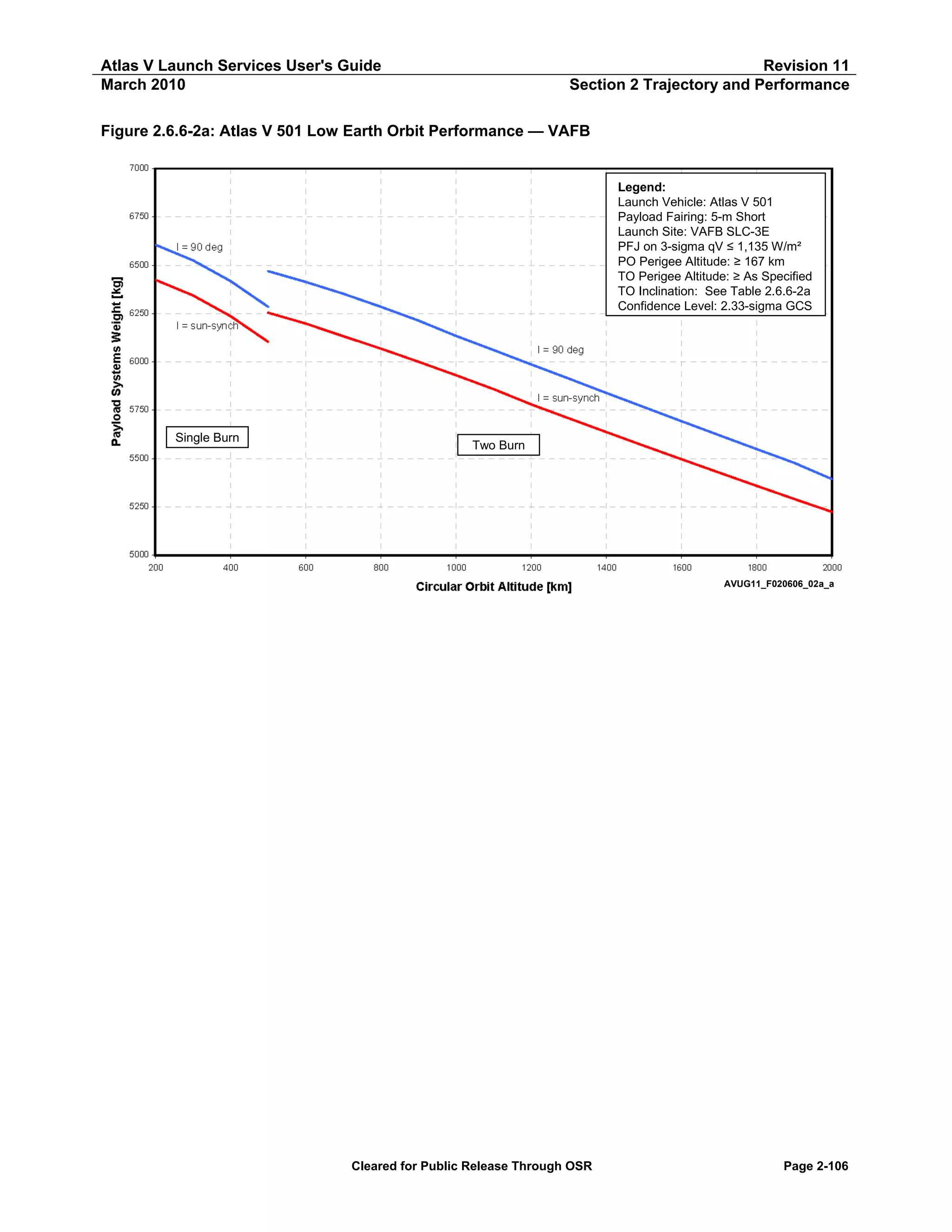
![Atlas V Launch Services User's Guide
March 2010
Revision 11
Section 2 Trajectory and Performance
Table 2.6.6-2a: Atlas V 501 Low Earth Orbit Performance — PSW vs Altitude
Atlas V 501 LEO — VAFB
Payload Systems Weight
I = 90 deg
Sun-Synch
[kg]
[lb]
[kg]
[lb]
Two Burn
5,393
11,890
5,224
11,517
5,477
12,076
5,291
11,664
5,549
12,232
5,358
11,813
5,620
12,390
5,427
11,964
5,693
12,550
5,496
12,117
5,765
12,710
5,566
12,271
5,839
12,872
5,637
12,427
5,913
13,035
5,708
12,584
5,987
13,199
5,780
12,742
6,060
13,361
5,859
12,916
6,133
13,522
5,930
13,074
6,213
13,698
6,001
13,229
6,285
13,856
6,068
13,378
6,352
14,004
6,132
13,519
6,414
14,140
6,198
13,665
6,469
14,263
6,253
13,786
Single Burn
6,285
13,855
6,103
13,455
6,418
14,149
6,236
13,749
6,524
14,384
6,343
13,984
6,606
14,563
6,424
14,163
Circular Orbit
Altitude
[km]
[nmi]
2,000
1,900
1,800
1,700
1,600
1,500
1,400
1,300
1,200
1,100
1,000
900
800
700
600
500
1,080
1,026
972
918
864
810
756
702
648
594
540
486
432
378
324
270
500
400
300
200
270
216
162
108
Notes:
Launch Site: VAFB SLC-3E
Payload Fairing: 5-m Short
PFJ at 3-sigma qV ≤ 1,135 W/m² (360 BTU/ft²-hr)
Park Orbit Perigee Altitude ≥ 167 km (90 nmi)
Confidence Level: 2.33 Sigma GCS
Cleared for Public Release Through OSR
Page 2-107](https://image.slidesharecdn.com/atlasvusersguide2010-140220084057-phpapp02/75/Atlas-v-usersguide2010-137-2048.jpg)
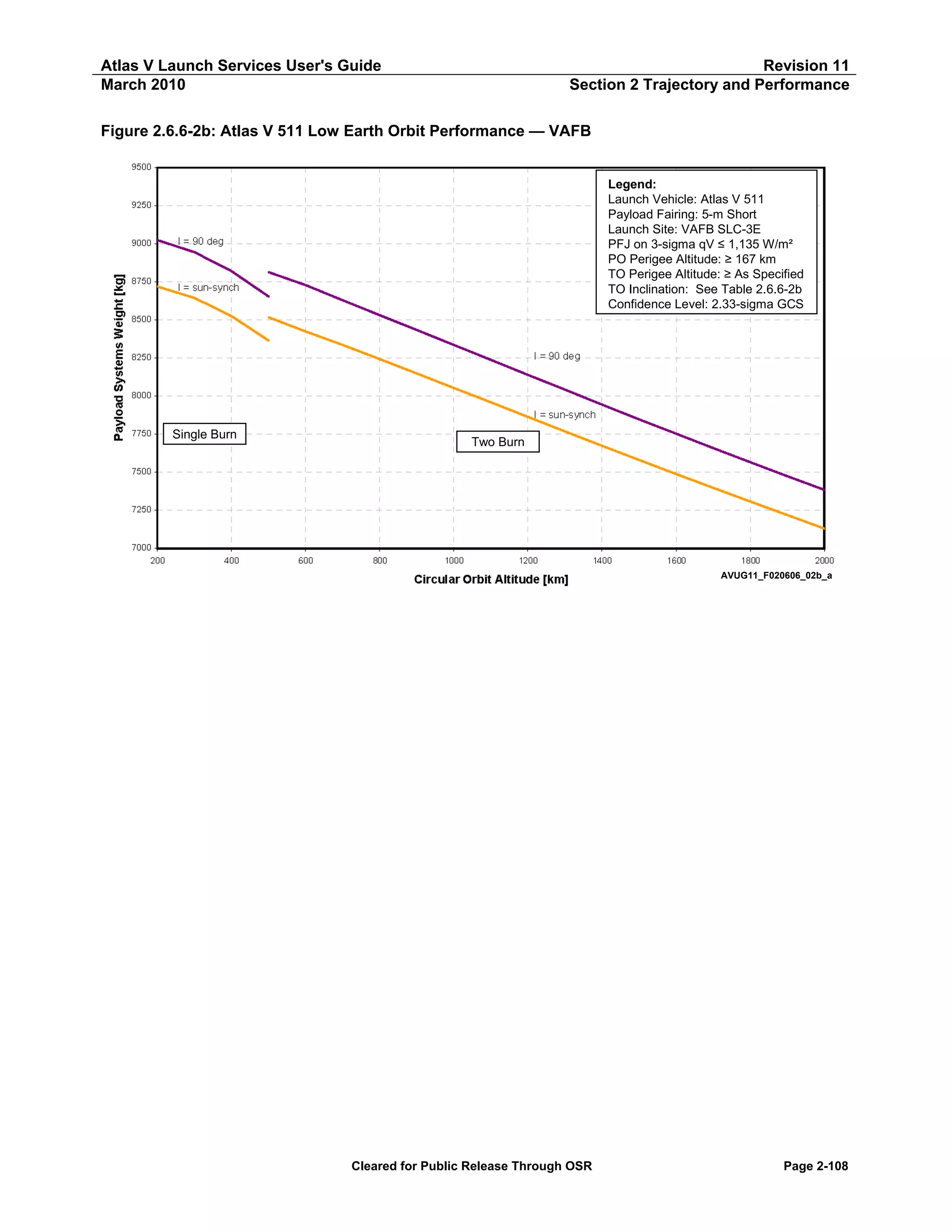
![Atlas V Launch Services User's Guide
March 2010
Revision 11
Section 2 Trajectory and Performance
Table 2.6.6-2b: Atlas V 511 Low Earth Orbit Performance — PSW vs Altitude
Atlas V 511 LEO — VAFB
Payload Systems Weight
I = 90 deg
Sun-Synch
[kg]
[lb]
[kg]
[lb]
Two Burn
7,383
16,278
7,130
15,720
7,474
16,476
7,218
15,913
7,565
16,677
7,307
16,108
7,658
16,882
7,397
16,307
7,752
17,090
7,487
16,507
7,847
17,300
7,580
16,710
7,944
17,513
7,673
16,917
8,041
17,728
7,768
17,125
8,139
17,944
7,862
17,334
8,238
18,161
7,958
17,544
8,336
18,377
8,053
17,754
8,433
18,593
8,148
17,963
8,531
18,807
8,242
18,171
8,629
19,023
8,335
18,376
8,728
19,243
8,424
18,572
8,814
19,431
8,517
18,776
Single Burn
8,653
19,078
8,364
18,440
8,821
19,446
8,526
18,796
8,944
19,718
8,644
19,056
9,023
19,892
8,719
19,223
Circular Orbit
Altitude
[km]
[nmi]
2,000
1,900
1,800
1,700
1,600
1,500
1,400
1,300
1,200
1,100
1,000
900
800
700
600
500
1,080
1,026
972
918
864
810
756
702
648
594
540
486
432
378
324
270
500
400
300
200
270
216
162
108
Notes:
Launch Site: VAFB SLC-3E
Payload Fairing: 5-m Short
PFJ at 3-sigma qV ≤ 1,135 W/m² (360 BTU/ft²-hr)
Park Orbit Perigee Altitude ≥ 167 km (90 nmi)
Confidence Level: 2.33 Sigma GCS
Cleared for Public Release Through OSR
Page 2-109](https://image.slidesharecdn.com/atlasvusersguide2010-140220084057-phpapp02/75/Atlas-v-usersguide2010-139-2048.jpg)
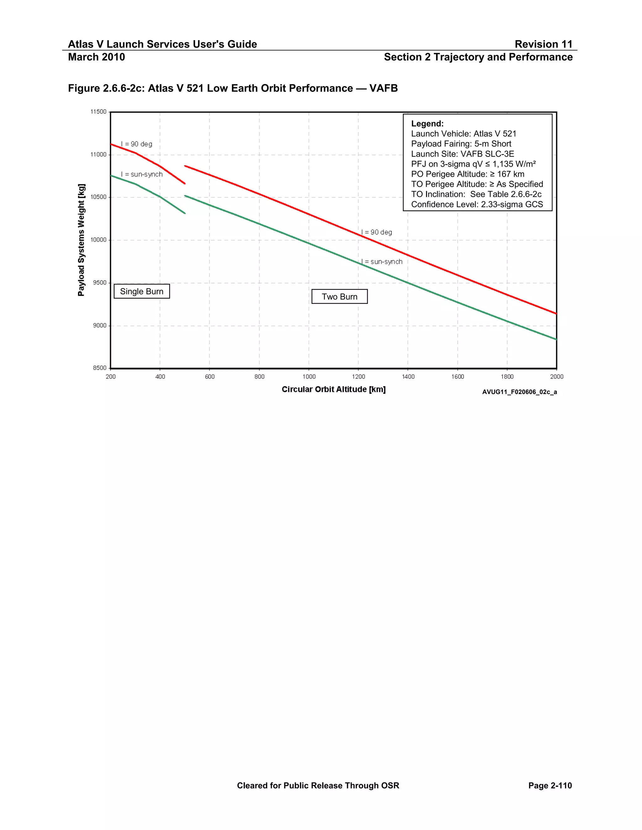
![Atlas V Launch Services User's Guide
March 2010
Revision 11
Section 2 Trajectory and Performance
Table 2.6.6-2c: Atlas V 521 Low Earth Orbit Performance — PSW vs Altitude
Atlas V 521 LEO — VAFB
Payload Systems Weight
I = 90 deg
Sun-Synch
[kg]
[lb]
[kg]
[lb]
Two Burn
9,139
20,147
8,837
19,482
9,250
20,392
8,944
19,718
9,362
20,640
9,052
19,957
9,476
20,891
9,162
20,200
9,591
21,145
9,274
20,445
9,708
21,403
9,387
20,695
9,826
21,662
9,501
20,946
9,945
21,925
9,616
21,200
10,065
22,189
9,732
21,454
10,185
22,453
9,848
21,710
10,304
22,717
9,963
21,965
10,423
22,979
10,078
22,218
10,540
23,236
10,191
22,467
10,655
23,489
10,303
22,713
10,765
23,733
10,410
22,950
10,870
23,965
10,521
23,195
Single Burn
10,661
23,505
10,313
22,737
10,865
23,953
10,508
23,166
11,021
24,297
10,658
23,496
11,125
24,527
10,758
23,717
Circular Orbit
Altitude
[km]
[nmi]
2,000
1,900
1,800
1,700
1,600
1,500
1,400
1,300
1,200
1,100
1,000
900
800
700
600
500
1,080
1,026
972
918
864
810
756
702
648
594
540
486
432
378
324
270
500
400
300
200
270
216
162
108
Notes:
Launch Site: VAFB SLC-3E
Payload Fairing: 5-m Short
PFJ at 3-sigma qV ≤ 1,135 W/m² (360 BTU/ft²-hr)
Park Orbit Perigee Altitude ≥ 167 km (90 nmi)
Confidence Level: 2.33 Sigma GCS
Cleared for Public Release Through OSR
Page 2-111](https://image.slidesharecdn.com/atlasvusersguide2010-140220084057-phpapp02/75/Atlas-v-usersguide2010-141-2048.jpg)
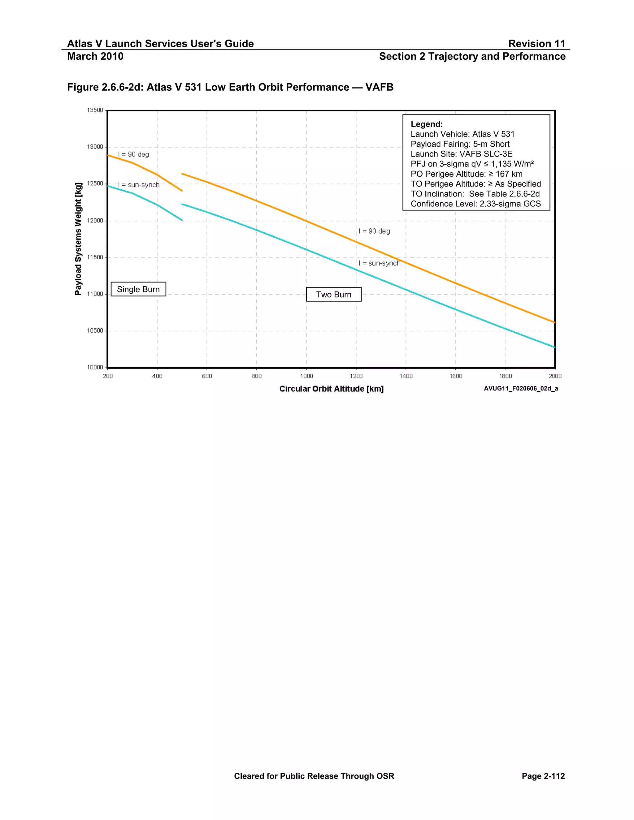
![Atlas V Launch Services User's Guide
March 2010
Revision 11
Section 2 Trajectory and Performance
Table 2.6.6-2d: Atlas V 531 Low Earth Orbit Performance — PSW vs Altitude
Atlas V 531 LEO — VAFB
Payload Systems Weight
I = 90 deg
Sun-Synch
[kg]
[lb]
[kg]
[lb]
Two Burn
10,615
23,403
10,276
22,655
10,746
23,691
10,403
22,934
10,879
23,985
10,531
23,217
11,015
24,283
10,661
23,504
11,151
24,585
10,794
23,796
11,290
24,891
10,927
24,091
11,431
25,200
11,062
24,389
11,571
25,511
11,198
24,688
11,713
25,823
11,335
24,989
11,855
26,136
11,472
25,291
11,996
26,446
11,608
25,590
12,135
26,754
11,742
25,886
12,271
27,054
11,873
26,175
12,403
27,343
12,000
26,455
12,527
27,617
12,119
26,718
12,640
27,866
12,228
26,957
Single Burn
12,406
27,352
12,007
26,472
12,625
27,833
12,215
26,930
12,790
28,197
12,374
27,280
12,893
28,424
12,473
27,498
Circular Orbit
Altitude
[km]
[nmi]
2,000
1,900
1,800
1,700
1,600
1,500
1,400
1,300
1,200
1,100
1,000
900
800
700
600
500
1,080
1,026
972
918
864
810
756
702
648
594
540
486
432
378
324
270
500
400
300
200
270
216
162
108
Notes:
Launch Site: VAFB SLC-3E
Payload Fairing: 5-m Short
PFJ at 3-sigma qV ≤ 1,135 W/m² (360 BTU/ft²-hr)
Park Orbit Perigee Altitude ≥ 167 km (90 nmi)
Confidence Level: 2.33 Sigma GCS
Cleared for Public Release Through OSR
Page 2-113](https://image.slidesharecdn.com/atlasvusersguide2010-140220084057-phpapp02/75/Atlas-v-usersguide2010-143-2048.jpg)
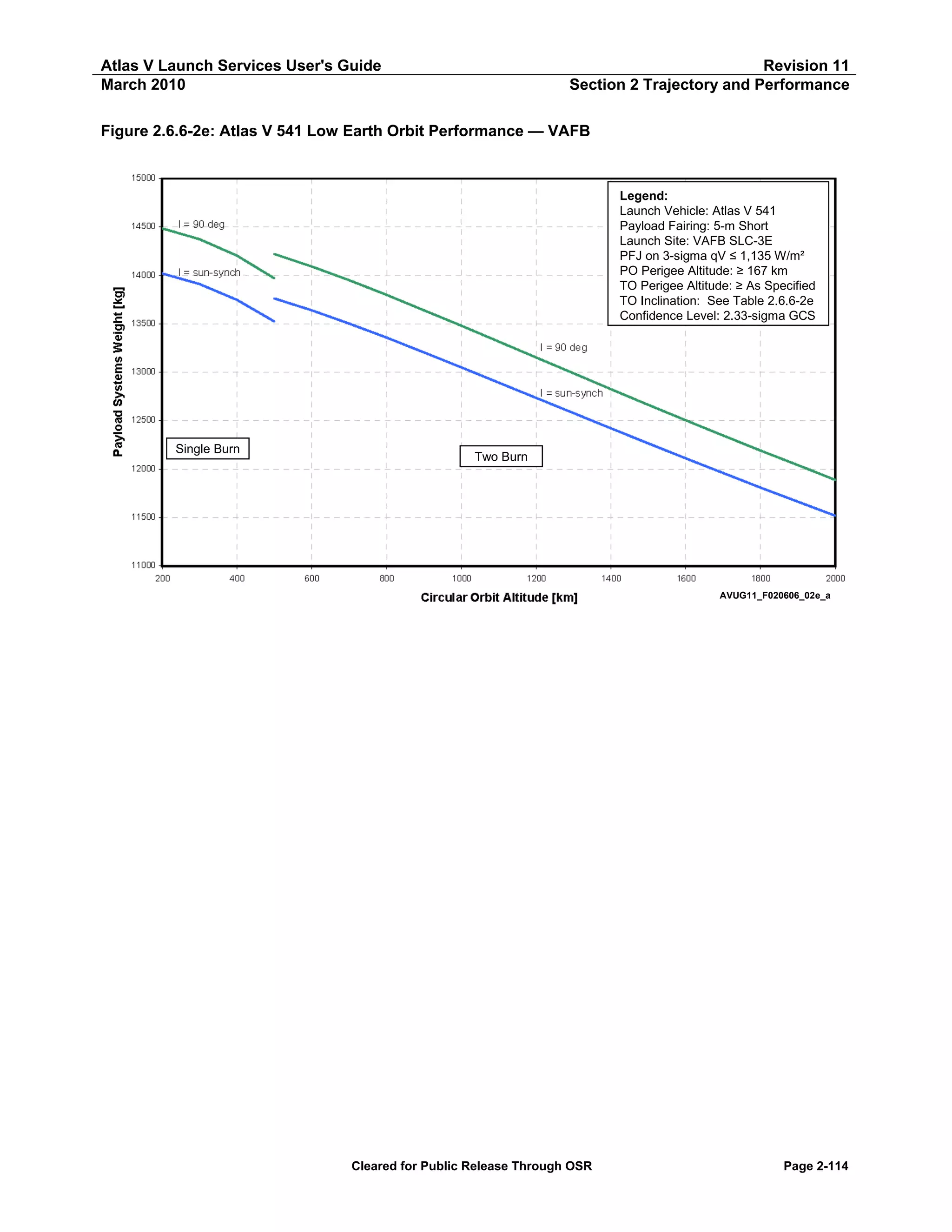
![Atlas V Launch Services User's Guide
March 2010
Revision 11
Section 2 Trajectory and Performance
Table 2.6.6-2e: Atlas V 541 Low Earth Orbit Performance — PSW vs Altitude
Atlas V 541 LEO — VAFB
Payload Systems Weight
I = 90 deg
Sun-Synch
[kg]
[lb]
[kg]
[lb]
Two Burn
11,888
26,209
11,517
25,390
12,039
26,542
11,662
25,710
12,191
26,877
11,809
26,034
12,346
27,219
11,958
26,364
12,503
27,564
12,110
26,698
12,663
27,916
12,264
27,038
12,825
28,273
12,420
27,381
12,988
28,633
12,577
27,727
13,152
28,994
12,734
28,074
13,315
29,355
12,892
28,422
13,479
29,716
13,049
28,769
13,640
30,071
13,205
29,111
13,798
30,419
13,356
29,445
13,949
30,753
13,502
29,766
14,092
31,067
13,638
30,067
14,220
31,350
13,761
30,338
Single Burn
13,969
30,797
13,524
29,816
14,203
31,312
13,746
30,304
14,372
31,685
13,909
30,665
14,484
31,932
14,019
30,908
Circular Orbit
Altitude
[km]
[nmi]
2,000
1,900
1,800
1,700
1,600
1,500
1,400
1,300
1,200
1,100
1,000
900
800
700
600
500
1,080
1,026
972
918
864
810
756
702
648
594
540
486
432
378
324
270
500
400
300
200
270
216
162
108
Notes:
Launch Site: VAFB SLC-3E
Payload Fairing: 5-m Short
PFJ at 3-sigma qV ≤ 1,135 W/m² (360 BTU/ft²-hr)
Park Orbit Perigee Altitude ≥ 167 km (90 nmi)
Confidence Level: 2.33 Sigma GCS
Cleared for Public Release Through OSR
Page 2-115](https://image.slidesharecdn.com/atlasvusersguide2010-140220084057-phpapp02/75/Atlas-v-usersguide2010-145-2048.jpg)
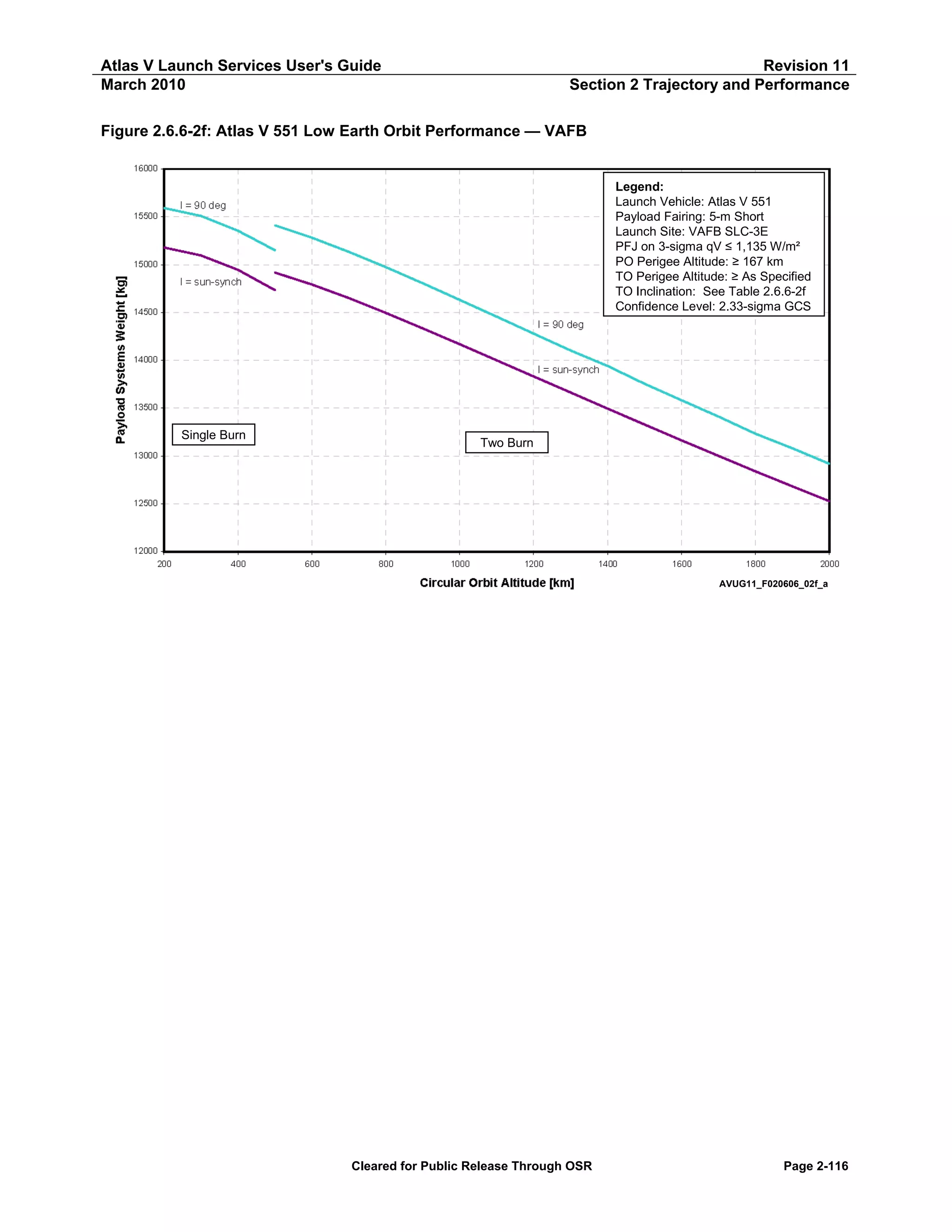
![Atlas V Launch Services User's Guide
March 2010
Revision 11
Section 2 Trajectory and Performance
Table 2.6.6-2f: Atlas V 551 Low Earth Orbit Performance — PSW vs Altitude
Atlas V 551 LEO — VAFB
Payload Systems Weight
I = 90 deg
Sun-Synch
[kg]
[lb]
[kg]
[lb]
Two Burn
12,917
28,477
12,526
27,614
13,079
28,833
12,681
27,958
13,231
29,170
12,839
28,306
13,411
29,566
13,000
28,659
13,581
29,941
13,162
29,018
13,753
30,321
13,327
29,382
13,940
30,731
13,494
29,749
14,102
31,090
13,661
30,118
14,279
31,480
13,830
30,490
14,456
31,869
14,000
30,864
14,631
32,256
14,168
31,235
14,804
32,637
14,334
31,601
14,972
33,009
14,495
31,956
15,133
33,363
14,649
32,296
15,282
33,691
14,792
32,611
15,410
33,972
14,917
32,887
Single Burn
15,151
33,403
14,734
32,482
15,352
33,846
14,945
32,949
15,508
34,189
15,095
33,279
15,591
34,373
15,179
33,464
Circular Orbit
Altitude
[km]
[nmi]
2,000
1,900
1,800
1,700
1,600
1,500
1,400
1,300
1,200
1,100
1,000
900
800
700
600
500
1,080
1,026
972
918
864
810
756
702
648
594
540
486
432
378
324
270
500
400
300
200
270
216
162
108
Notes:
Launch Site: VAFB SLC-3E
Payload Fairing: 5-m Short
PFJ at 3-sigma qV ≤ 1,135 W/m² (360 BTU/ft²-hr)
Park Orbit Perigee Altitude ≥ 167 km (90 nmi)
Confidence Level: 2.33 Sigma GCS
Cleared for Public Release Through OSR
Page 2-117](https://image.slidesharecdn.com/atlasvusersguide2010-140220084057-phpapp02/75/Atlas-v-usersguide2010-147-2048.jpg)
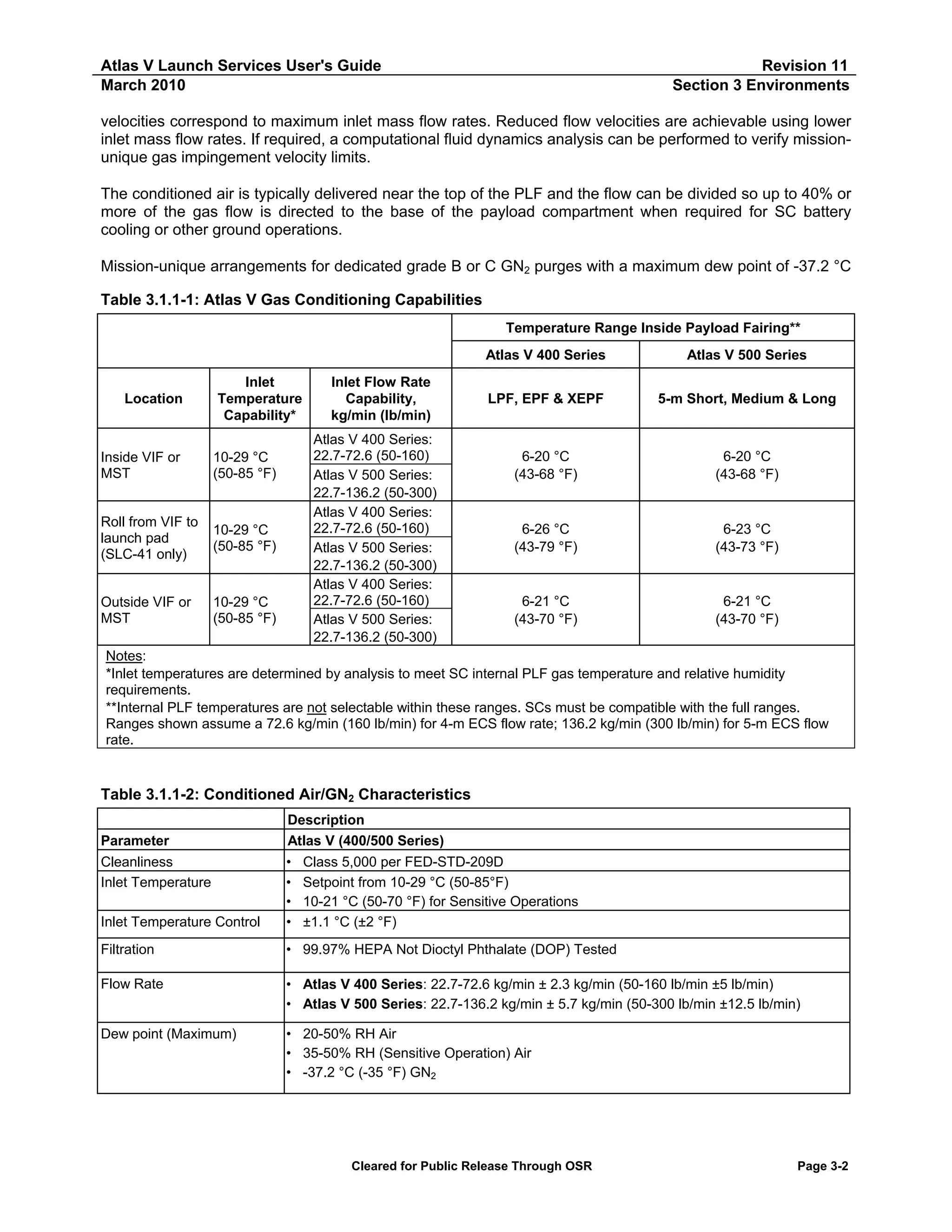

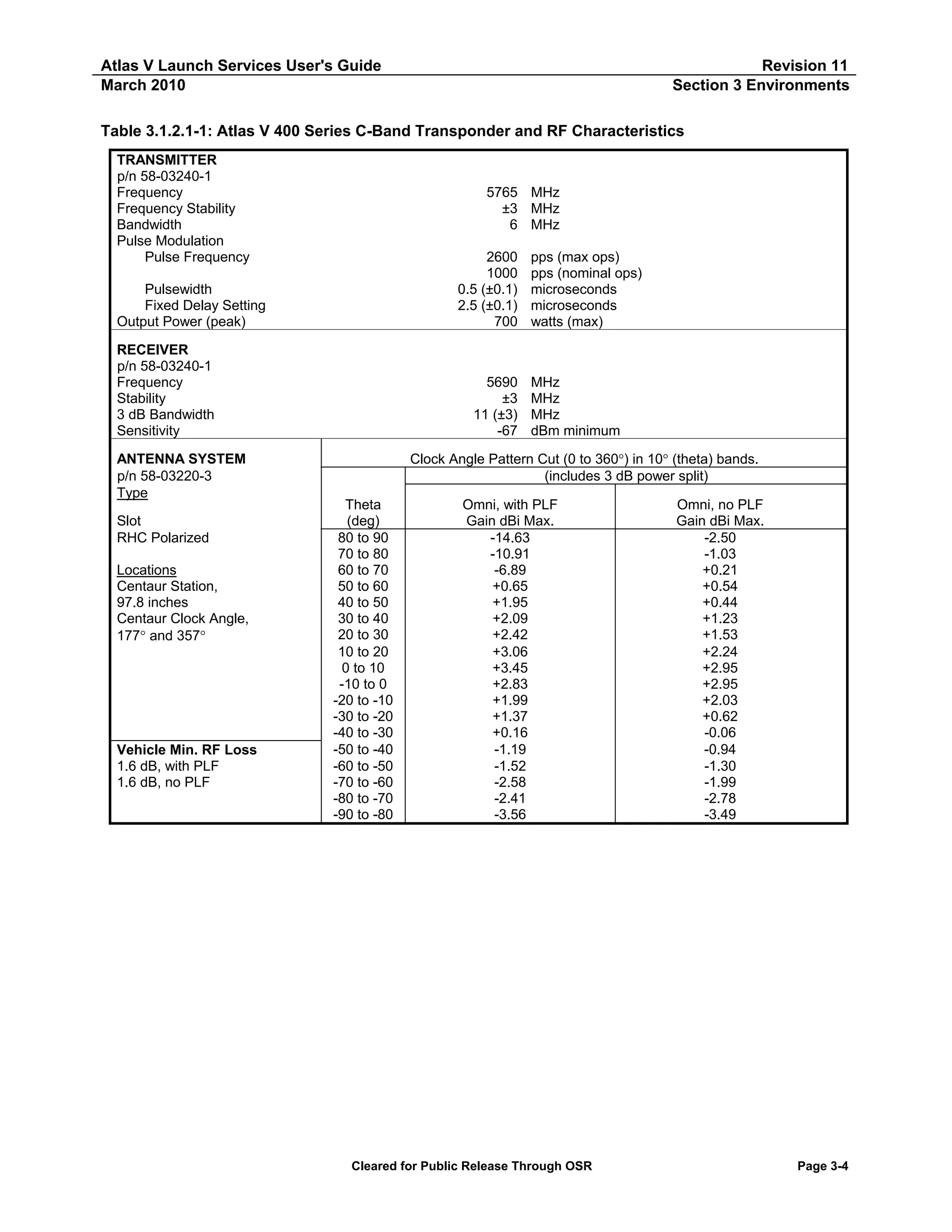
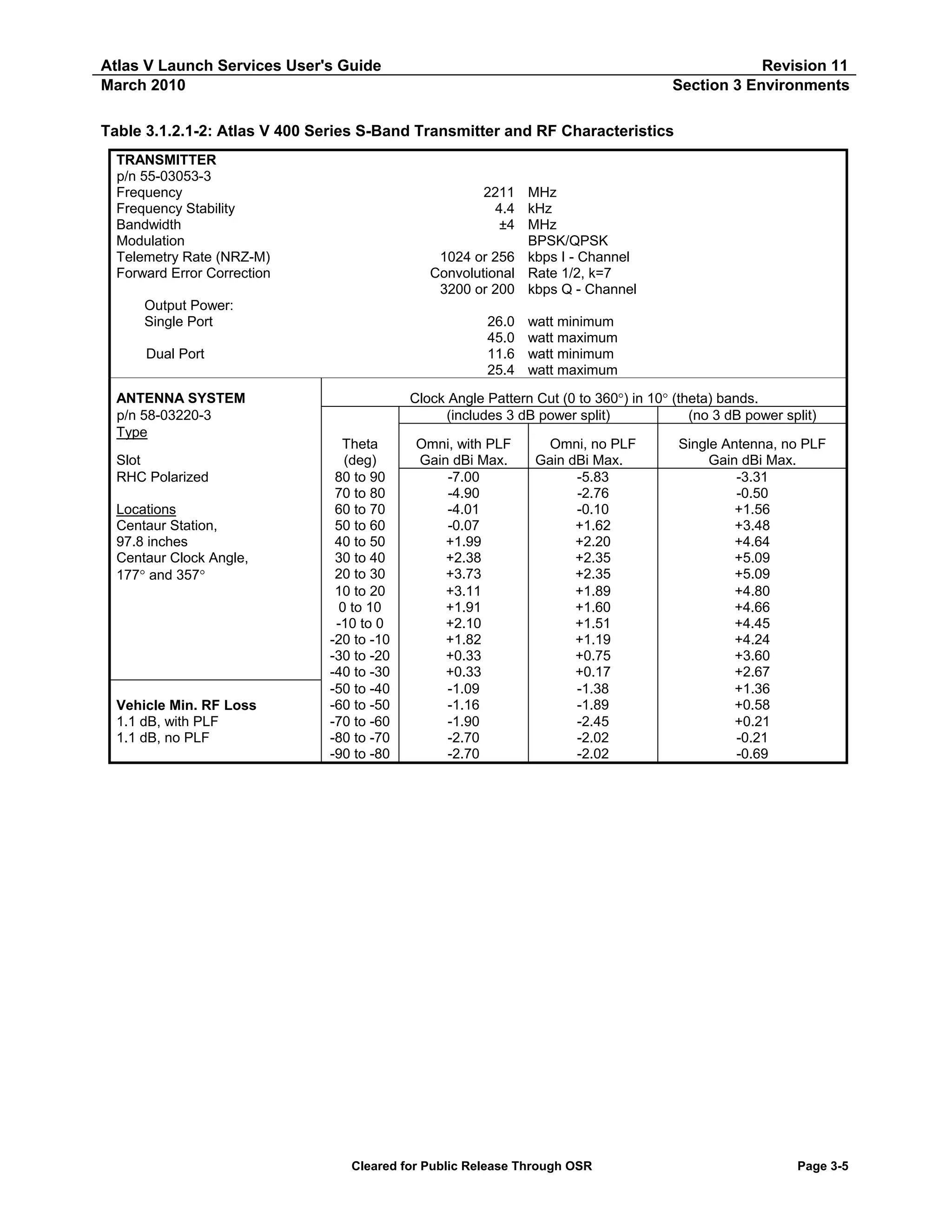
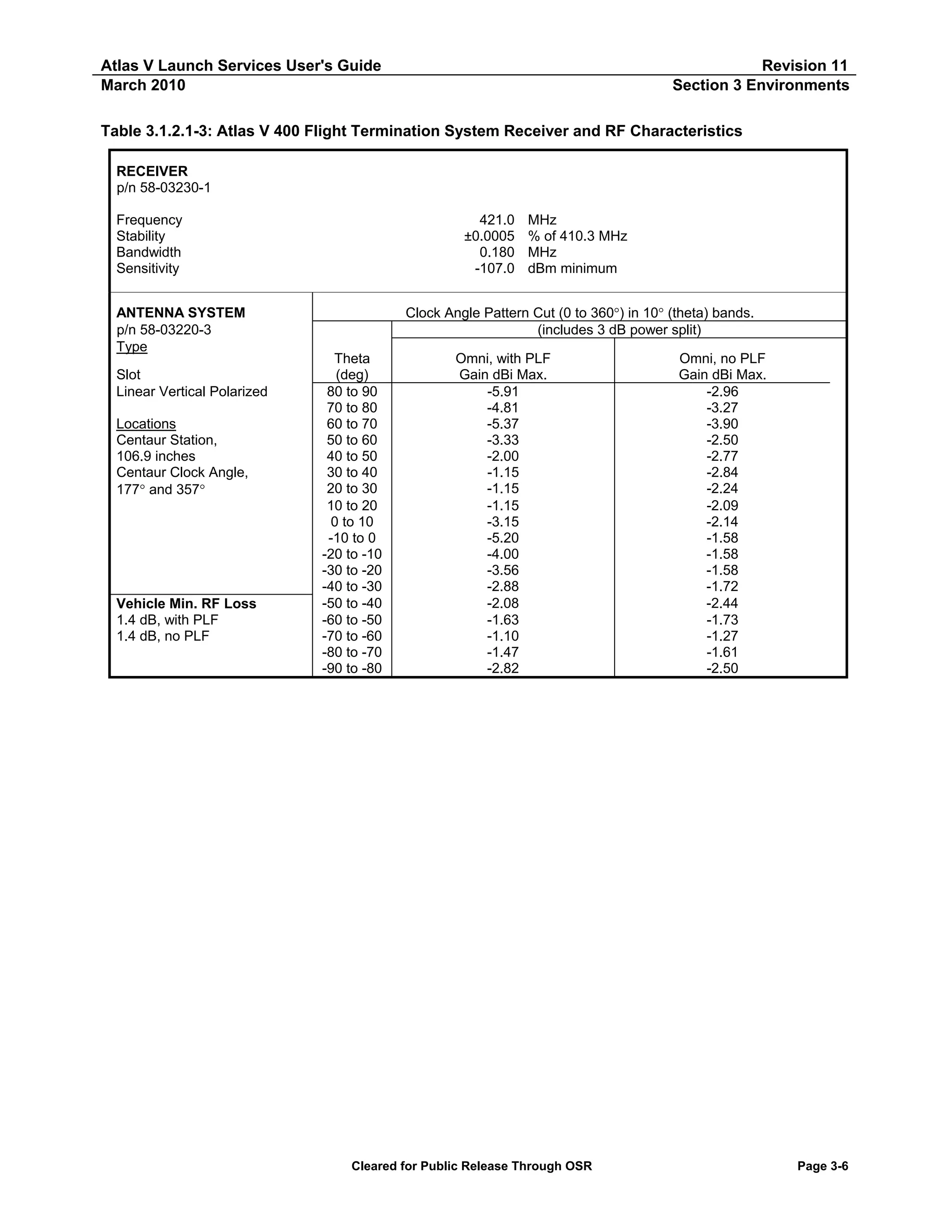
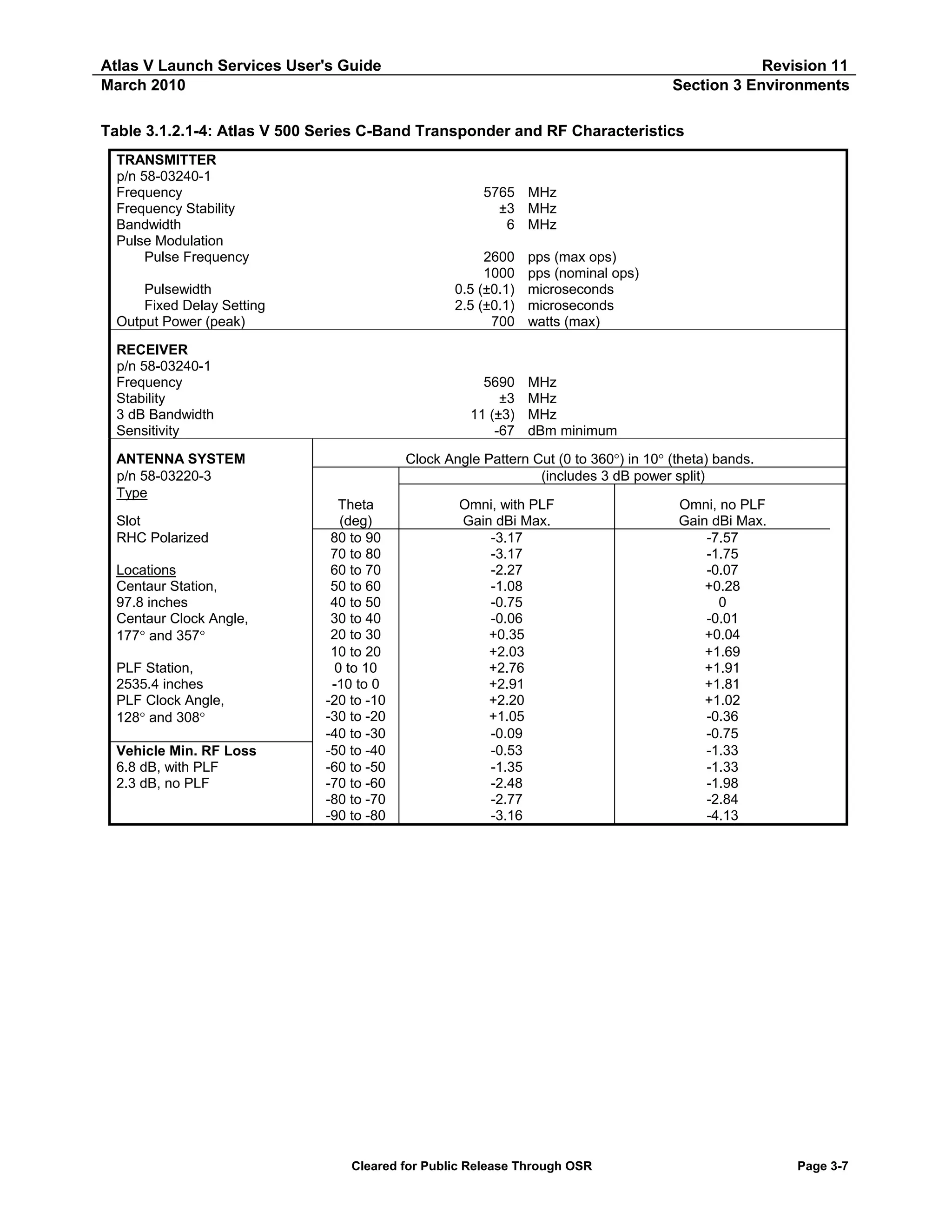
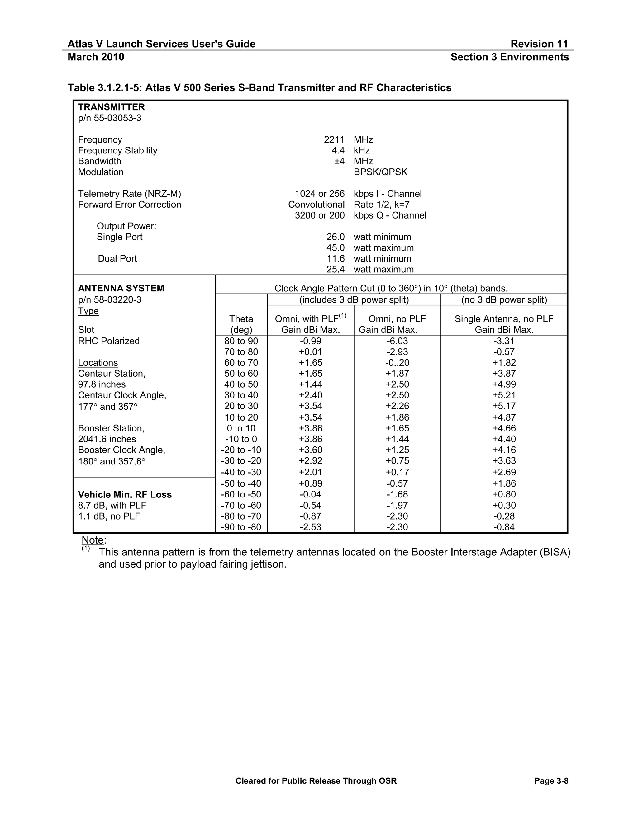
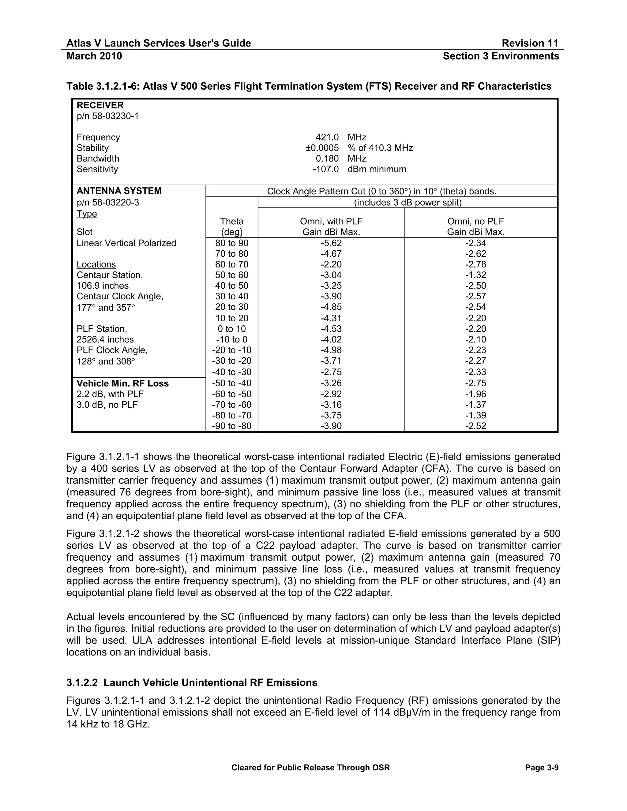
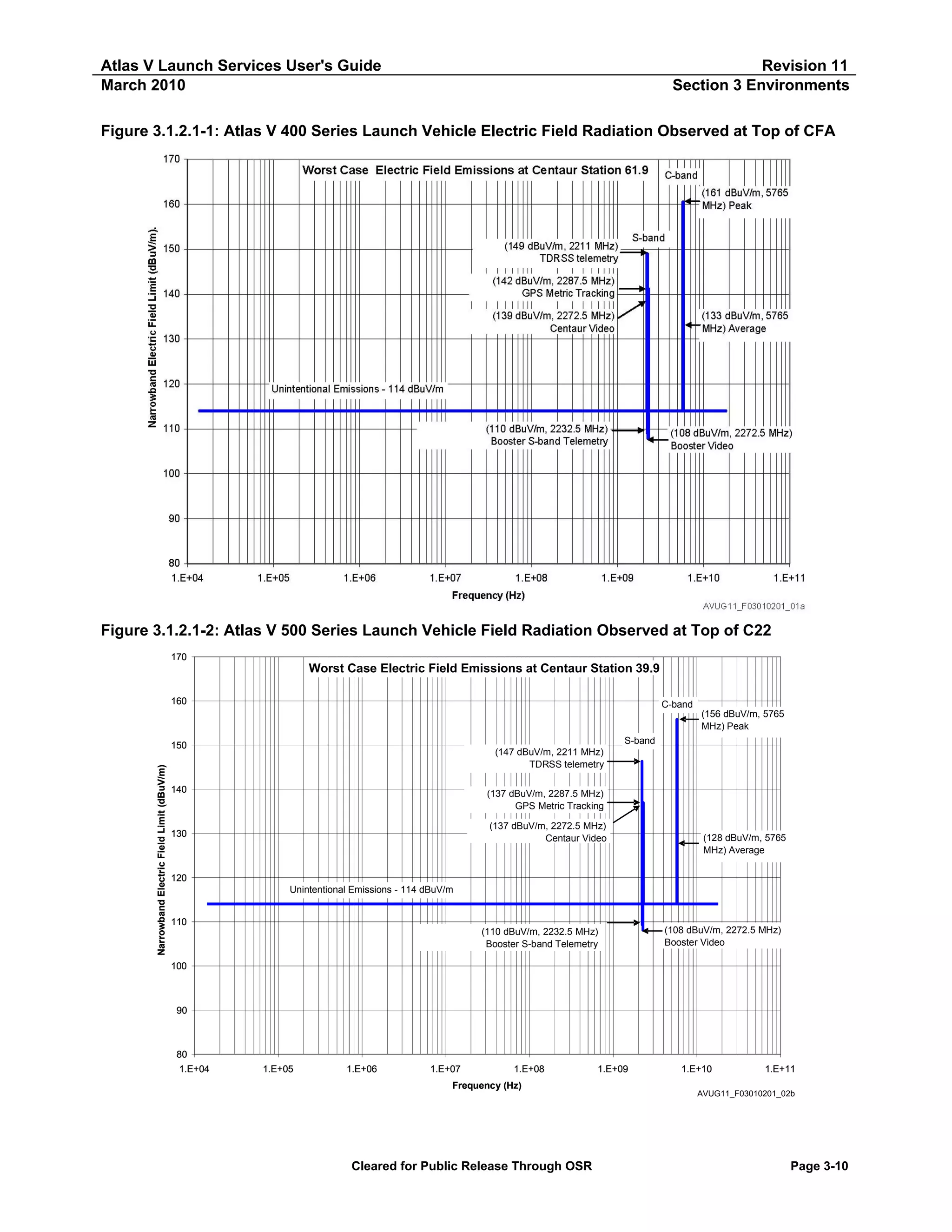
![Atlas V Launch Services User's Guide
March 2010
Revision 11
Section 3 Environments
Table 3.1.2.3-1: Worst-Case (Peak) RF Environment during Transport from Astrotech Spaceflight
Operations to SLC-41
Emitter Name
CSAS Orbit
Radar ARSR-4
Frequency
(1)
(MHz)
406.5/416.5/421
.0
1244.06,
1326.92
1784.74
2025 to 2110
2710
2702.6-2897.5
2750 & 2840
2865
3049.4
3049.4
3050
5550
5570
5625
5625
5640
5690
5690
5710
5690
5690
5690
5525
Theoretical Intensity
(1) (3)
(V/m)
(Peak)
0.33
Duty Cycle(1) (2)
Typical Mitigation(1)
1.0
None
1.54
0.0432
[Topography]
GPS Grnd Antenna
2.47
1.0
None
NASA STDN
6.39
1.0
None
Miscellaneous #1
6.58
0.0012
None
Miscellaneous #2
1.19
0.0008
None
Miscellaneous #3
6.13
0.0008
None
WSR-88D (NEXRAD)
14.57
0.006
None
SRB Retrieval Ship (S-Band)
4.49
0.00072
None
SRB Retrieval Ship (S-Band)(6)
276.12
0.00072
None
Miscellaneous #4
2.20
0.00072
None
Channel 9 Weather
17.38
0.010
None
[Topography]
Channel 2 Weather
6.47
0.0032
WSR-74C
12.62
0.0064
None
TDR 43-250 (Dec. 08)
22.19
0.0030
None
TDWR
[Topography]
14.36
0.010
Procedure Mask
Radar 0.14 (0.134)
83.97
0.0016
Radar 1.16
60.31
0.00064
PRD Action Required
Radar 19.39
83.09
0.005
PRD Action Required
Radar 19.14
182.78
0.0016
PRD Action Required
Radar 19.17
104.53
0.0008
PRD Action Required
Radar 28.14
[Topography]
15.82
0.0016
PRD Action Required
NDR (MCR) C-Band Pulse
204.31
0.004
5 Degree elevation
Doppler
SRB Retrieval Ship (X-Band)
9413.6
1.08
0.00072
None
SRB Retrieval Ship (X-Band)(6)
9413.6
66.64
0.00072
None
Miscellaneous #5
9410
3.37
0.00072
None
ET Barge Tug
9410
69.57
0.00072
None
Miscellaneous #6
9410
645.22
(70)
0.00072
Masking Measured
Miscellaneous #7
9410
2.40
0.00072
None
Miscellaneous #8(7)
9455
5.78
0.0024
None
Cruise Ships
9410
2.84
None
0.0012
NASA X-Band CW Hangar
10490, 10499
5.19
1.0
None
(Liberty)
NASA X-Band CW (LCU)
10490, 10499
1.73
1.0
None
NASA Avian Detector
9410
6.46
0.0005
None
(5)
Radar Test Bed
5690
30.03
0.0016
None
Note:
(1)
Majority data taken from Aerospace TOR-2005(1663)-3790, "Cape Canaveral Spaceport Radio Frequency
Environment," November 2005, Rev. G (UFOUO)
(2)
Avg. V/m = PkV/m*sqrt (Duty Cycle).
(3)
Non-shaded sources are without specific mechanical or software mitigation measures; bold sources have
masking/mechanical or topography and italicized sources indicate no masking or topography controls.
(4)
Measured E-fields indicated by ( ) – measurements performed during the WGS SC-1 transport.
(5)
Radar Test Bed is pointing up when not in use.
(6)
Results based on SRB Retrieval Ship being used as ET Barge tug vessel.
(7)
Radar is not yet installed.
Cleared for Public Release Through OSR
Page 3-12](https://image.slidesharecdn.com/atlasvusersguide2010-140220084057-phpapp02/75/Atlas-v-usersguide2010-160-2048.jpg)

2.25
0.93
4.46
1.06
1.0
1.0
.0012
0.0008
None
None
None
None
(2)
Miscellaneous #3
5.19
(2.18)
0.0008
None
Measured
WSR-88D (NEXRAD)
12.69
(0.10)
0.006
[Topography](5) Measured
SRB Retrieval Ship (S-Band)
3.58
0.00072
None
SRB Retrieval Ship (S-Band)(8)
16.91
0.00072
None
Miscellaneous #4
1.59
0.00072
None
Channel 9 Weather
9.930
0.010
None
Channel 2 Weather
4.66
0.0032
[Topography](5)
WSR-74C
10.58
(0.07)
0.0064
None
Measured
TDR 43-250 (Dec. 08)
10.39
0.0030
None
(5)
TDWR
9.97
0.010
[Topography]
(4)
Procedure Mask
Radar 0.14 (0.134)
71.7
0.0016
Procedure Mask
Radar 1.16
52.6(4)
0.00064
(4)
Procedure Mask
Radar 19.39
29.8
0.005
Procedure Mask
Radar 19.14
106.4(4)
0.0016
Procedure Mask
Radar 19.17
55.1(4)
0.0008
(5)
Radar 28.14
15.5
0.0016
Topography
(4)
5 Degree Elevation
NDR (MCR) C-Band Pulse
173.0
0.004
Doppler
SRB Retrieval Ship (X-Band)
9413.6
0.86
0.00072
None
SRB Retrieval Ship (X-Band)(8)
9413.6
4.08
0.00072
None
Miscellaneous #5 (X-Band)
9410
2.43
0.00072
None
Miscellaneous #6
9410
41.93
(0.13)
0.00072
Masking
Measured
Miscellaneous #7
9410
1.94
0.00072
None
ET Barge Tug
9410
4.17
0.0012
None
Miscellaneous #8(9)
9455
3.52
0.0024
None
Cruise Ships
9410
2.19
0.0012
None
NASA X-Band CW Hanger
10490, 10499
4.15
1.0
None
(Liberty)
NASA X-Band CW (LCU)
10490, 10499
1.73
1.0
None
NASA Avian Detector
9410
2.41
0.0005
None
(7)
Radar Test Bed
5690
25.52
0.0016
None
Majority data taken from Aerospace TOR-2005(1663)-3790, "Cape Canaveral Spaceport Radio Frequency
(1)
Environment," November 2005, Rev. G (UFOUO)
Avg. V/m = PkV/m*sqrt (Duty Cycle).
(2)
Non-shaded sources are without specific mechanical or software mitigation measures; bold sources have
(3)
masking/mechanical or topography and italicized sources indicate no masking or topography controls.
In-flight tracking levels for Tracking Radars (0.14, 1.16, 19.39, 19.14, 19.17 and NASA C-Band) are typically 20
(4)
V/m.
E-field levels are above the VIF/MLP – E-fields will be seen after launch.
(5)
Measured E-fields indicated by ( ) – in VIF at Level 6 – Test Report, BOEING-KSC-N120-53434-05 dated 9
(6)
February 2005.
Radar Test Bed is pointing up when not in use.
(7)
Results based on closest approach during ET Barge transit.
(8)
Cleared for Public Release Through OSR
Page 3-13](https://image.slidesharecdn.com/atlasvusersguide2010-140220084057-phpapp02/75/Atlas-v-usersguide2010-161-2048.jpg)
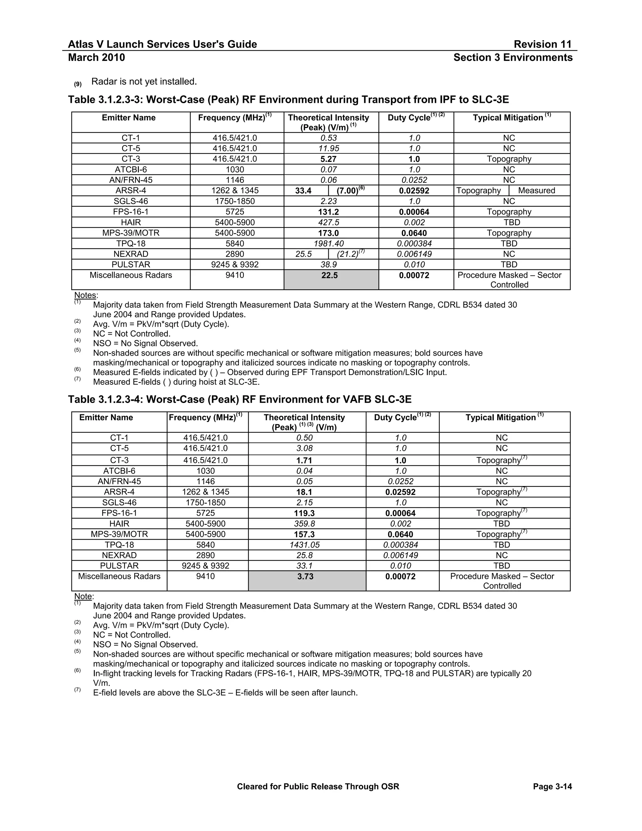
![Atlas V Launch Services User's Guide
March 2010
Revision 11
Section 3 Environments
3.1.2.4 Spacecraft-Generated EMC Environment Limitation
During ground and launch operation time frames through SC separation, any SC Electromagnetic
Interference (EMI) radiated emissions (including antenna radiation) should not exceed values depicted in
Figure 3.1.2.4-1. LV/SC external interfaces (EMI-conducted emissions) must be examined individually. SC
shall provide available unintentional radiated emissions data to the LV in the frequency ranges from 410 to
430 MHz, 1500 to 1650 MHz, and from 5660 to 5720 MHz.
Each SC will be treated on a mission-unique basis. Assurance of the LV/SC EMC with respect to payload
emissions will be a shared responsibility between ULA and the SC contractor.
Figure 3.1.2.4-1: Spacecraft Electric Field Radiation Impingement on Launch Vehicle
180
LV Radiated Susceptibility at Top of CFA
(1GHz, 160 dBuV/m)
(18GHz, 160 dBuV/m)
160
[140 dBuV/m
(350 MHz)]
Narrowband Electric Field (dBuV/m)
140
120
[114 dBuV/m
(14 kHz)]
Maximum Allowable Field Strength
100
80
73 dBuV/m
(5660-5720 MHz)
60
40
Note: Curve Includes 6 dB Safety Margin
20
0
1.E+04
37 dBuV/m
(410-430 MHz)
1.E+05
1.E+06
1.E+07
1.E+08
Frequency, Hz
[39 dBuV/m]
[1500-1650 MHz]
1.E+09
1.E+10
1.E+11
AVUG11_F03010204_01a
3.1.2.5 Electrostatic Discharge Events
3.1.2.5.1
Centaur Non-Conductive Materials
The Centaur vehicle, depending on the trajectory employed to deliver the SC to orbit, can fly through parts of
the Earth’s Magnetic L-shells. If the trajectory up through SC separation altitude and location (as determined
by ULA) indicates no passage beyond an L-shell value of 5.5, charging of the Centaur non-conductive
materials will not occur. However, if the trajectory indicates passage beyond an L-shell of 5.5, charging of the
Centaur non-conductive materials can occur resulting in an Electrostatic Discharge (ESD) event. Figure
3.1.2.5.1-1 displays the expected peak ESD broadband E-field emissions that would be present at various
SIP stations, starting at the top of the CFA (4m SIP station 0.0, 5m SIP station -22.0) and going forward.
Note that SIP stations are given for both Atlas V 400 and 500 series vehicles.
Cleared for Public Release Through OSR
Page 3-15](https://image.slidesharecdn.com/atlasvusersguide2010-140220084057-phpapp02/75/Atlas-v-usersguide2010-163-2048.jpg)
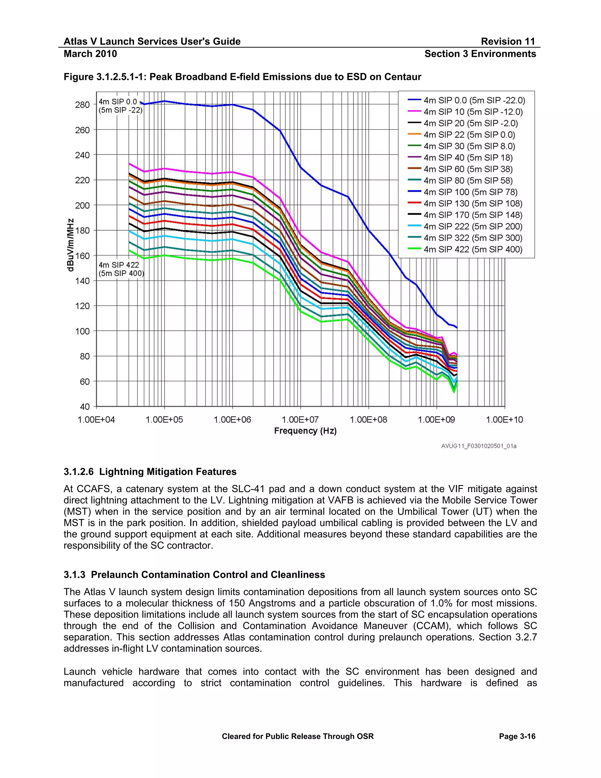
![Atlas V Launch Services User's Guide
March 2010
Revision 11
Section 3 Environments
“contamination critical.” Contamination critical surfaces include the Centaur forward adapter, PLF interior,
boattail interior, payload adapter, and for the 5-m PLFs, the top of the Centaur forward load reactor.
In addition, ground operations at the launch site have been designed to ensure a clean environment for the
SC. A comprehensive Contamination Control Plan has been written to identify these requirements and
procedures. A mission-unique appendix will be written to supplement the contamination control plan if the
mission-unique requirements identified in the ICD are more stringent than those baselined in the control
plan. Some guidelines and practices used in the plan are found in the following paragraphs. Analysis of LV
contamination of the SC is discussed in Section 4.2.11.
3.1.3.1 Contamination Control Before Launch Site Delivery
Design and Assembly — ULA implements contamination control principles in design and manufacturing
processes to limit the amount of contamination from LV components. Interior surfaces include maintainability
features to facilitate the removal of manufacturing contaminants. Contamination-critical hardware is entered
into a controlled production phase in which the hardware is cleaned and maintained clean to prevent
contaminants in difficult-to-clean places at the end of production. To support this effort, final assembly of
payload adapters, the PLF, and the Centaur vehicle is performed in a Class 100,000 facility to ensure that
hardware surfaces and, in particular, any entrapment areas are maintained at an acceptable level of
cleanliness before shipment to the launch site. Inspection points verify cleanliness throughout the assembly
process. Approved clean room wrapping protects critical surfaces during contaminant generating activities.
Materials Selection — In general, ULA selects materials for contamination-critical hardware inside the PLF
that will not become a source of contamination to the SC. Metallic or nonmetallic materials that are known to
chip, flake, or peel are prohibited. Materials that are cadmium-plated, zinc-plated, or made of unfused
electrodeposited tin are avoided inside the PLF volume. Corrosion-resistant materials are selected wherever
possible and dissimilar materials are avoided or protected according to MIL-STD-889B. Because most
nonmetallic materials are known to exhibit some out gassing, these materials are evaluated against criteria
that were developed using NASA SP-R-0022 as a starting point.
3.1.3.2 Contamination Control Before Spacecraft Encapsulation
Cleanliness Levels — Contamination-critical hardware surfaces are cleaned and inspected to Visibly Clean
Level 2. These checks confirm the absence of all particulate and molecular contaminants visible to the
2
unaided eye at a distance of 15.2-45.7 cm (6-18 in.) with a minimum illumination of 1,076 lumen/m
(100 foot-candles [fc]). Hardware cleaned to this criterion at the assembly plant is protected to maintain this
level of cleanliness through shipping and encapsulation.
Contingency cleaning may also be required to restore this level of cleanliness if the hardware becomes
contaminated. Contingency cleaning procedures outside of the encapsulation facility before encapsulation
are subject to Atlas V program engineering approval. The cognizant SC engineer must approve any required
cleaning of LV hardware in the vicinity of the SC.
Certain SC may require that contamination critical hardware surfaces be cleaned to a level of cleanliness
other than Visibly Clean Level 2. Because additional cleaning and verification may be necessary, these
requirements are implemented on a mission-unique basis.
PLF Cleaning Techniques — The Atlas V program recognizes that cleaning of large, interior PLF surfaces
depends on implementation of well-planned cleaning procedures. To achieve customer requirements, all
cleaning procedures are verified by test, reviewed and approved by Material and Processes Engineering.
Final PLF cleaning and encapsulation is performed in a Class 100,000 facility.
Cleanliness Verification — The Atlas V program visually inspects all contamination-critical hardware
surfaces to verify Visibly Clean Level 2 criteria as described above. For Atlas V, contamination critical
Cleared for Public Release Through OSR
Page 3-17](https://image.slidesharecdn.com/atlasvusersguide2010-140220084057-phpapp02/75/Atlas-v-usersguide2010-165-2048.jpg)
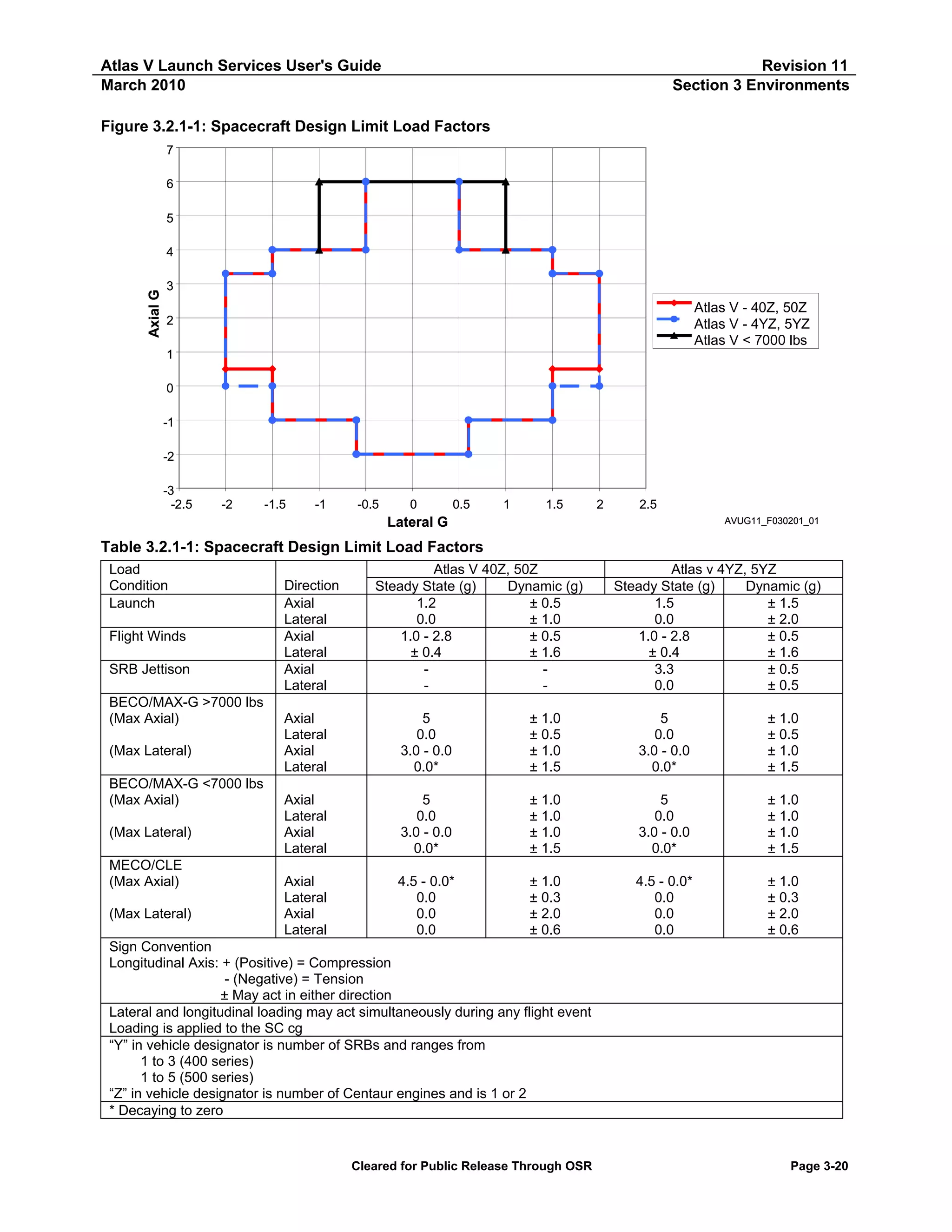
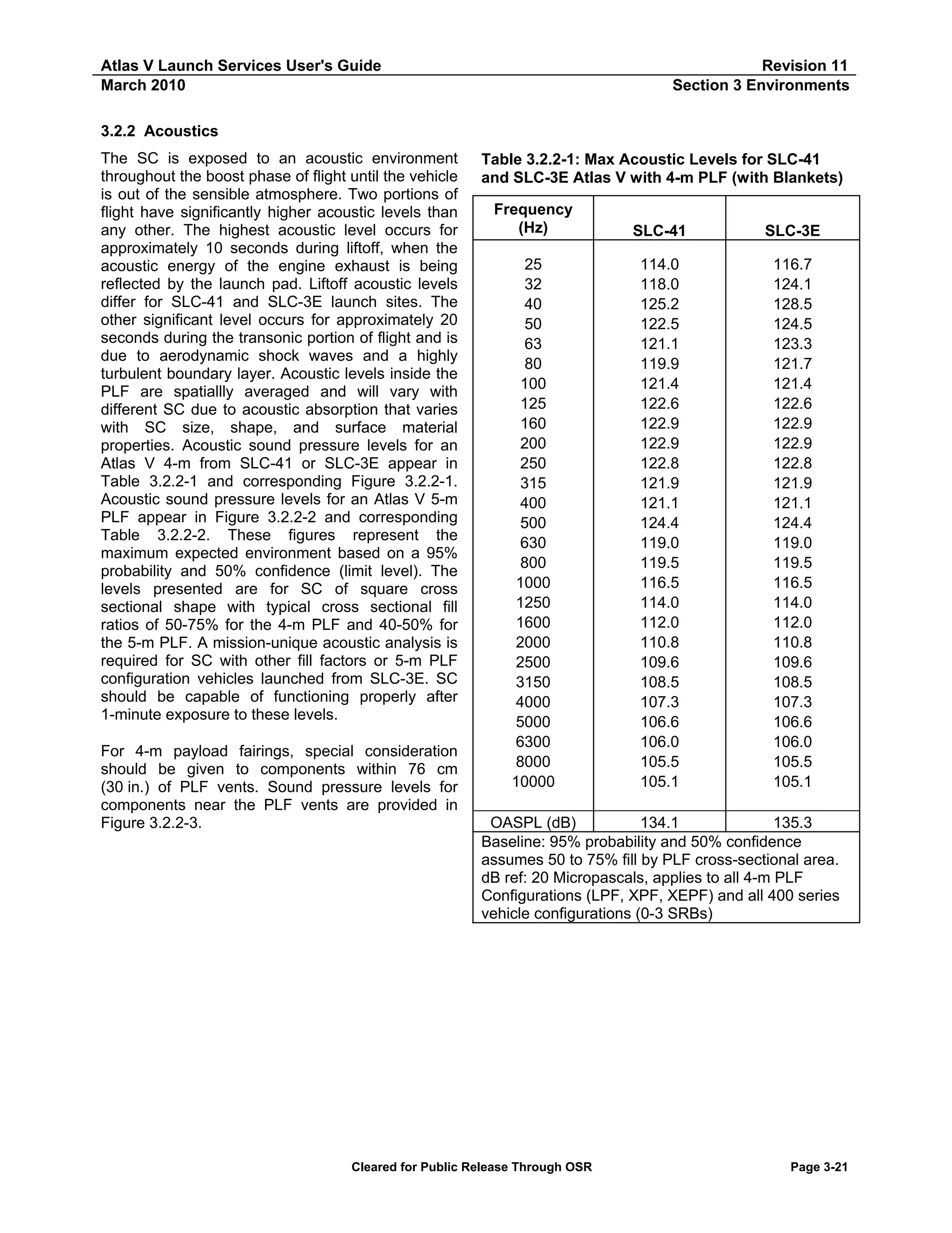
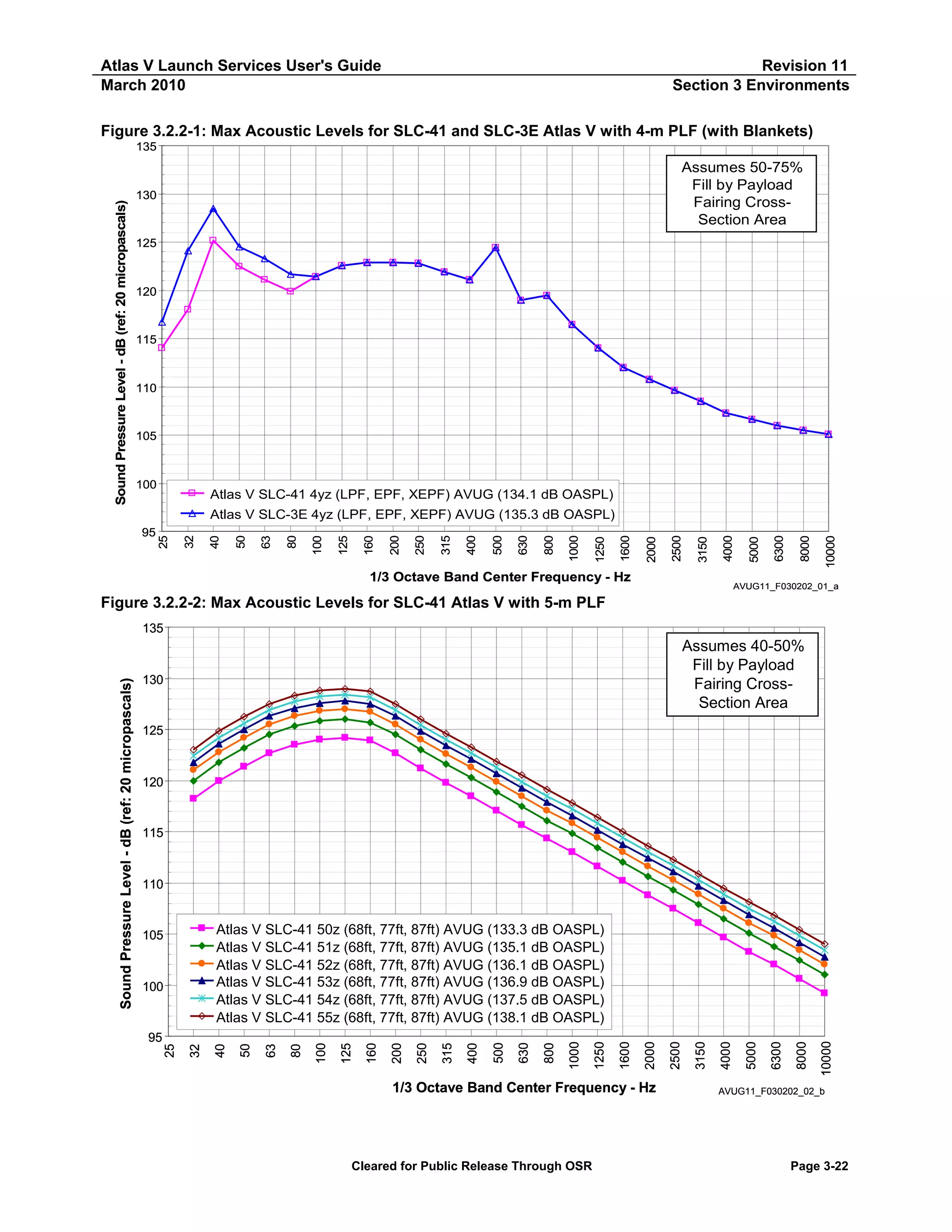
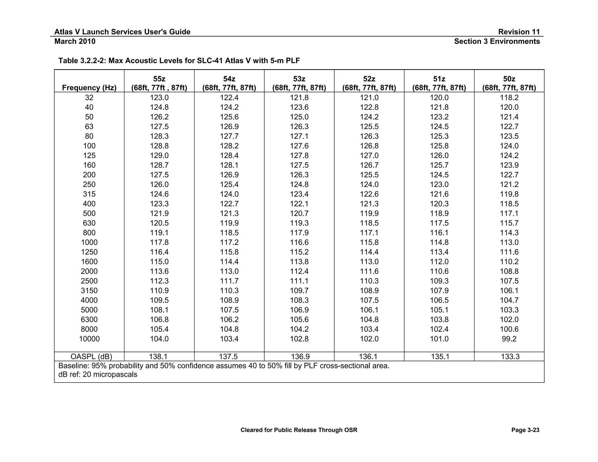
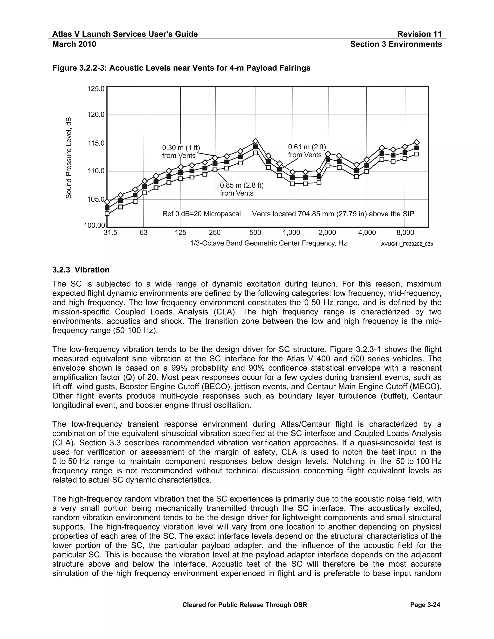
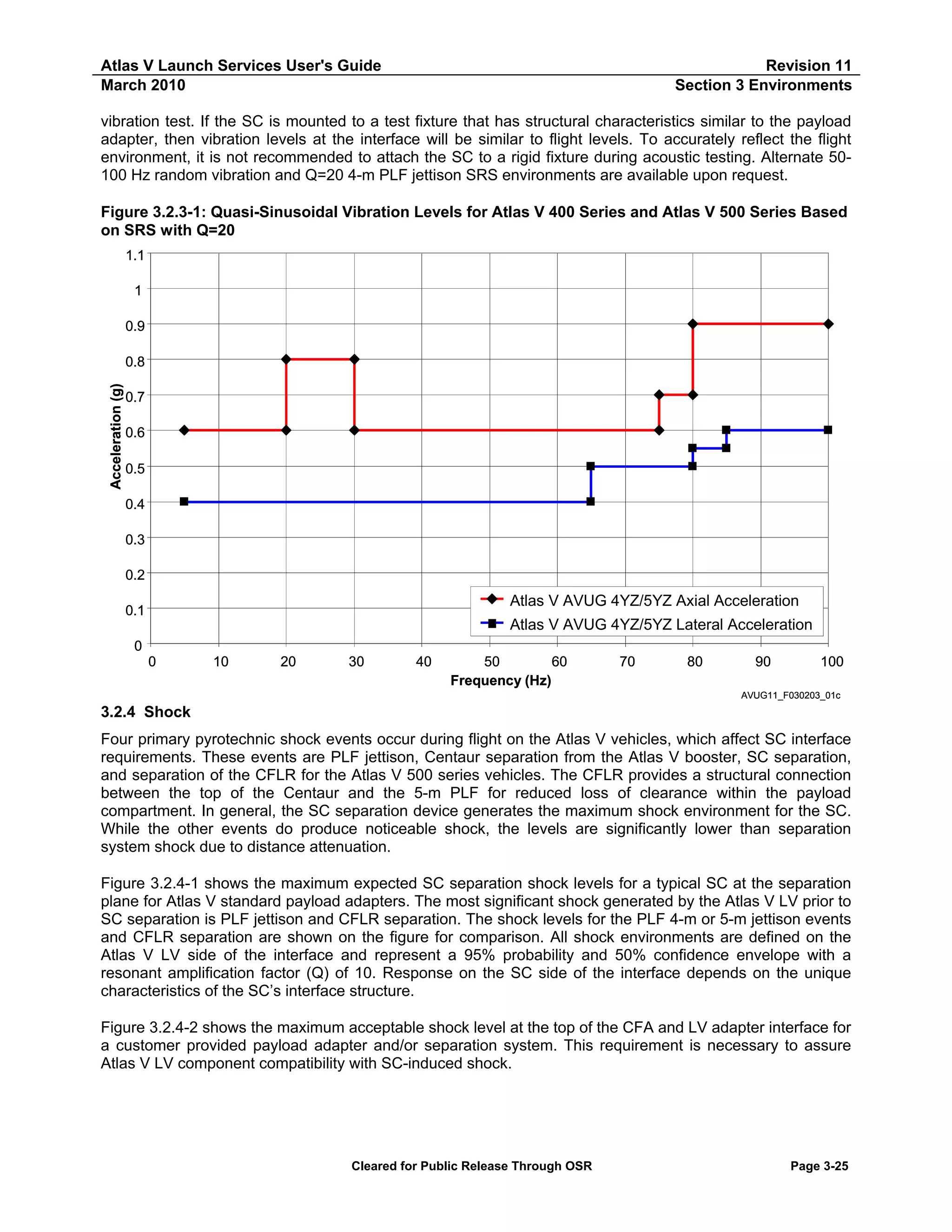
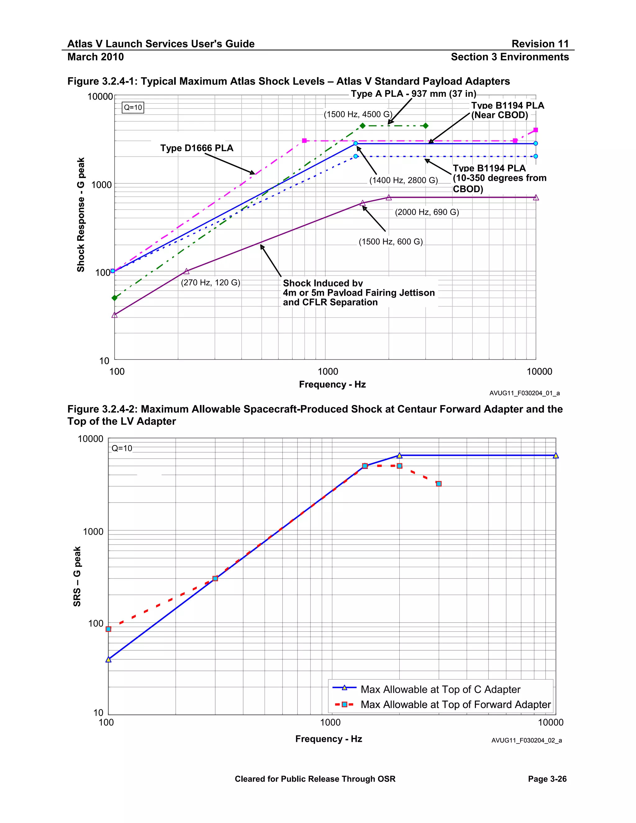
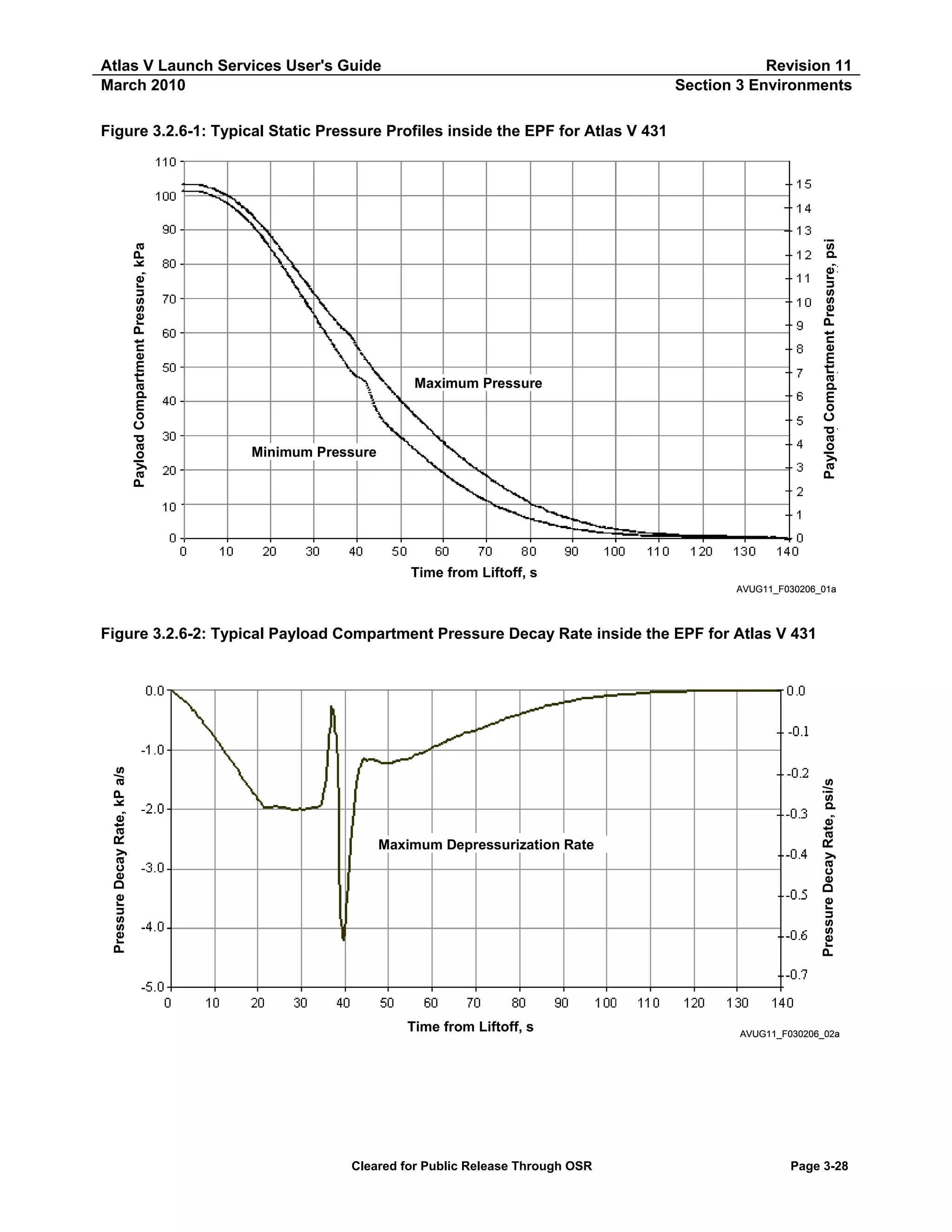
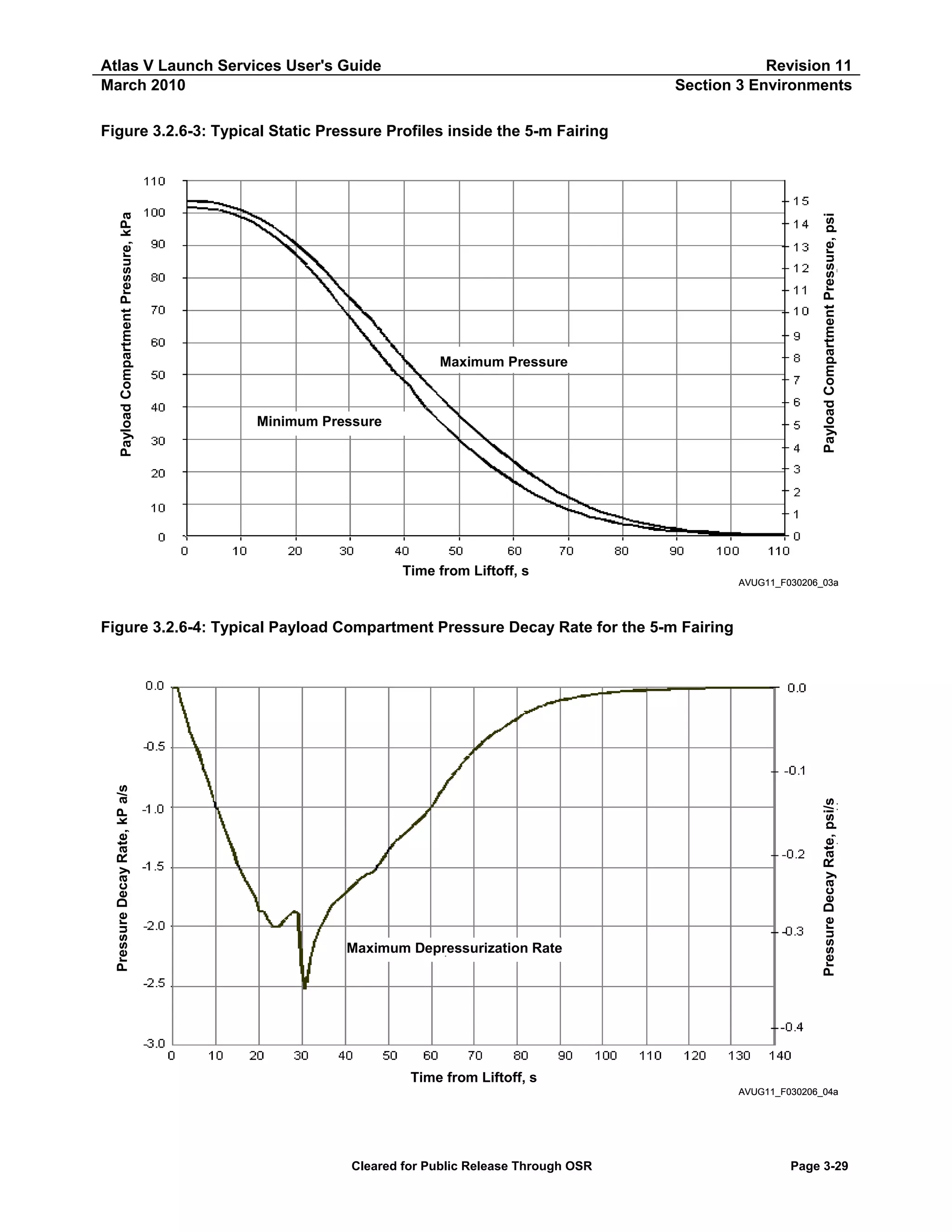
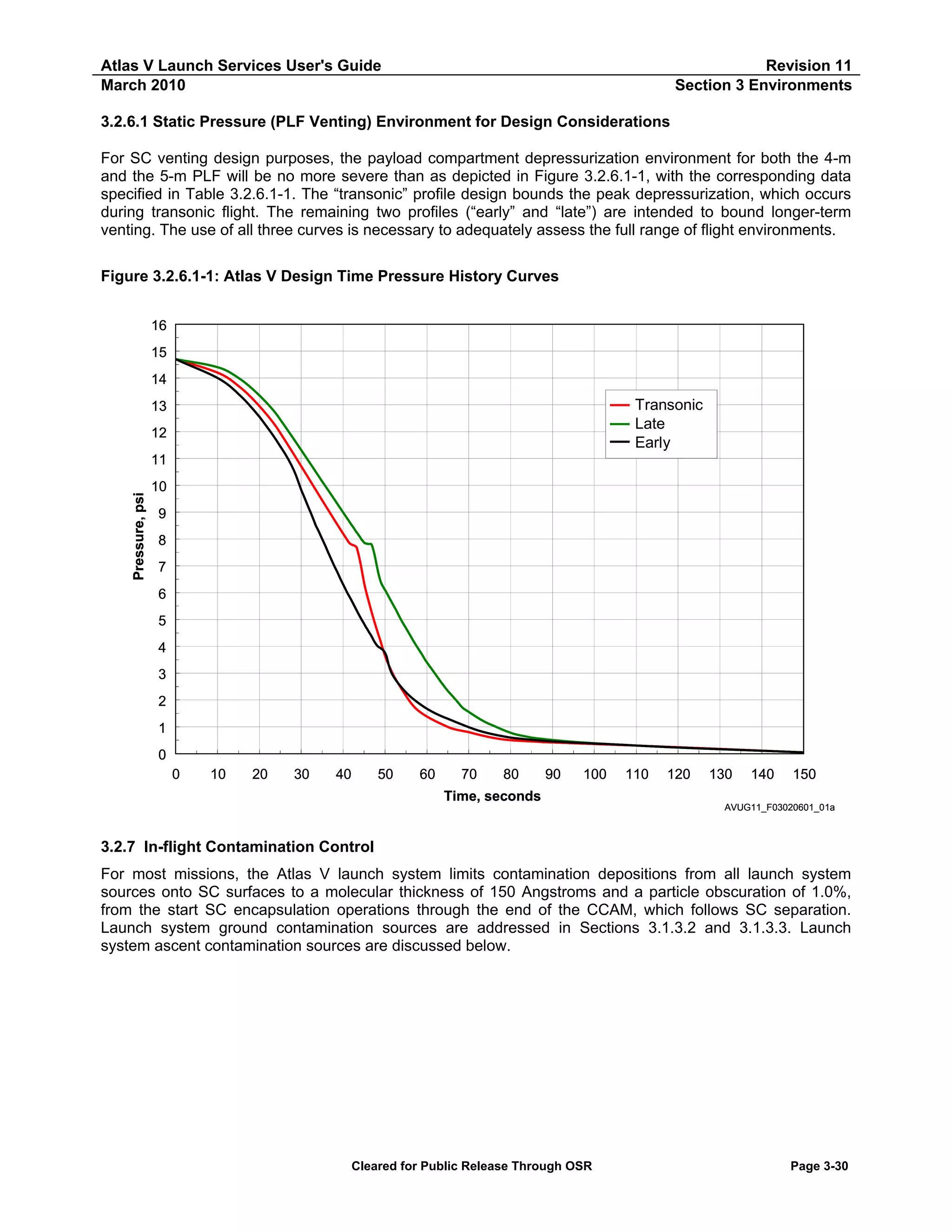
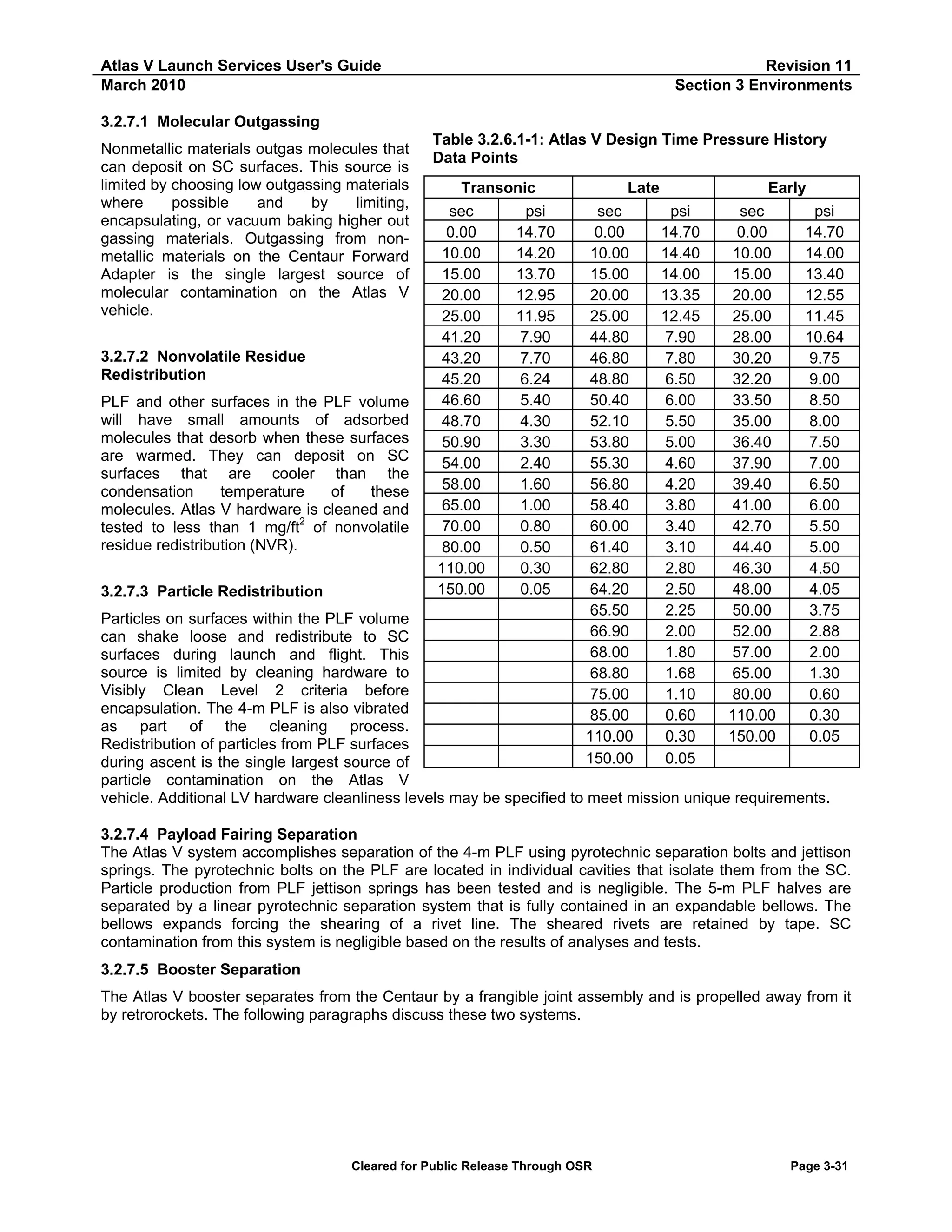
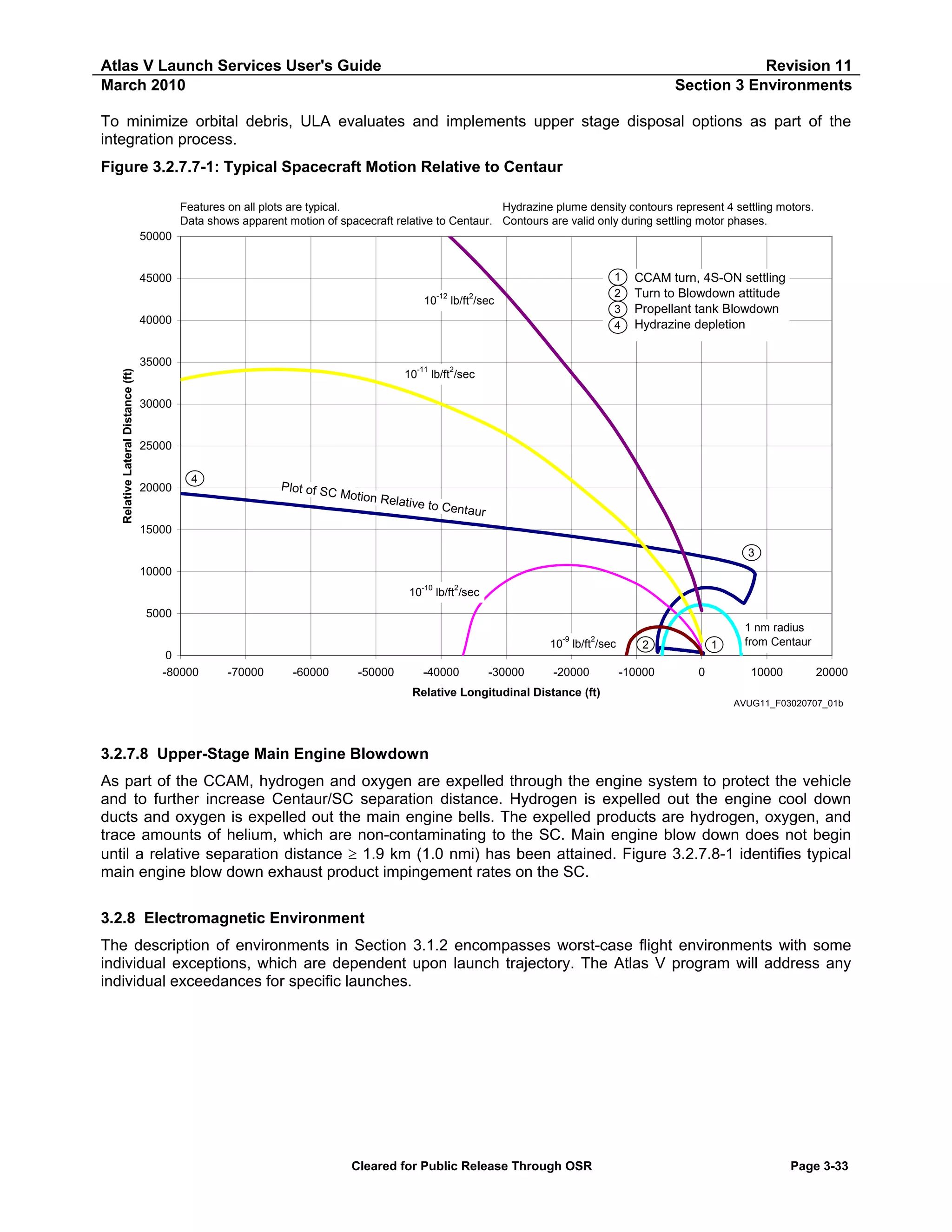
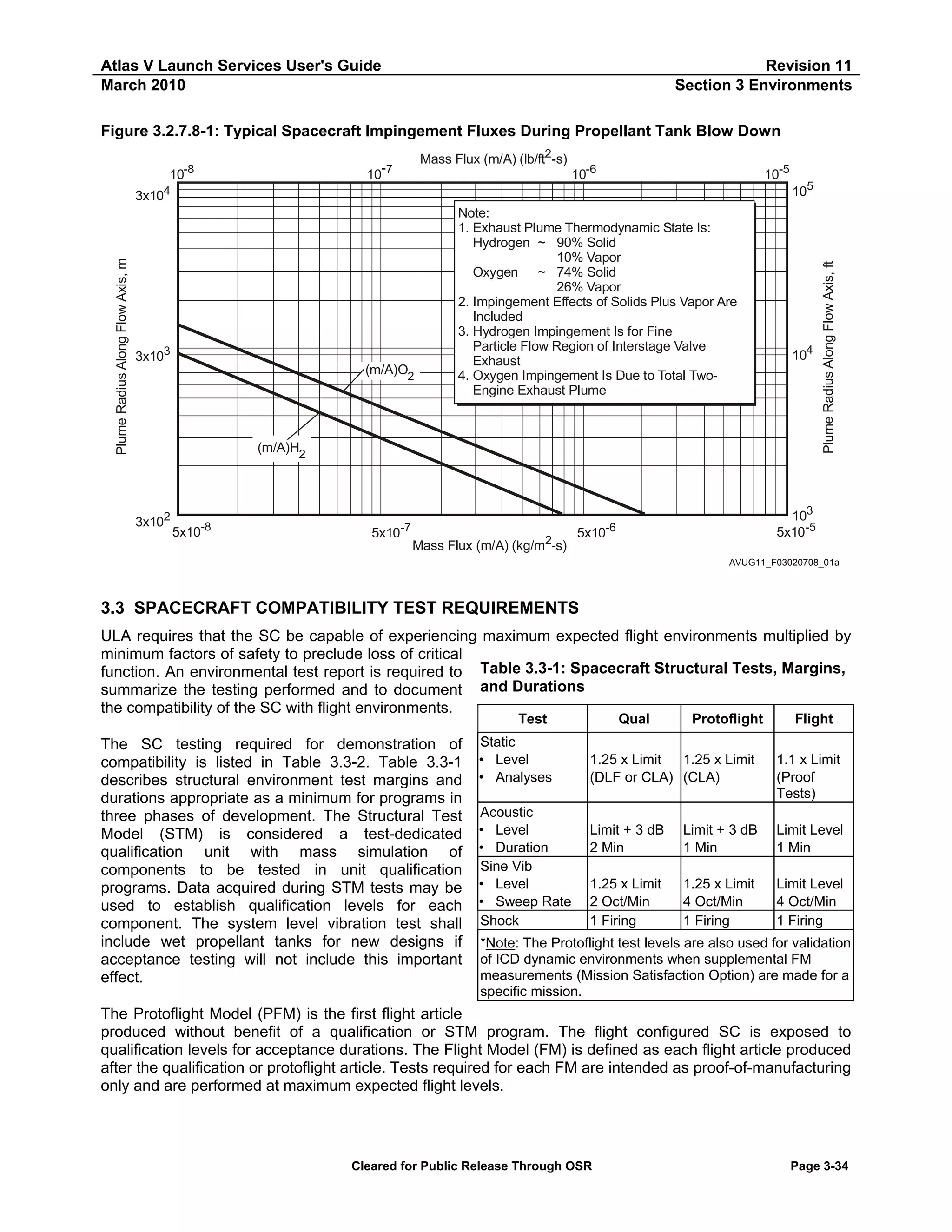
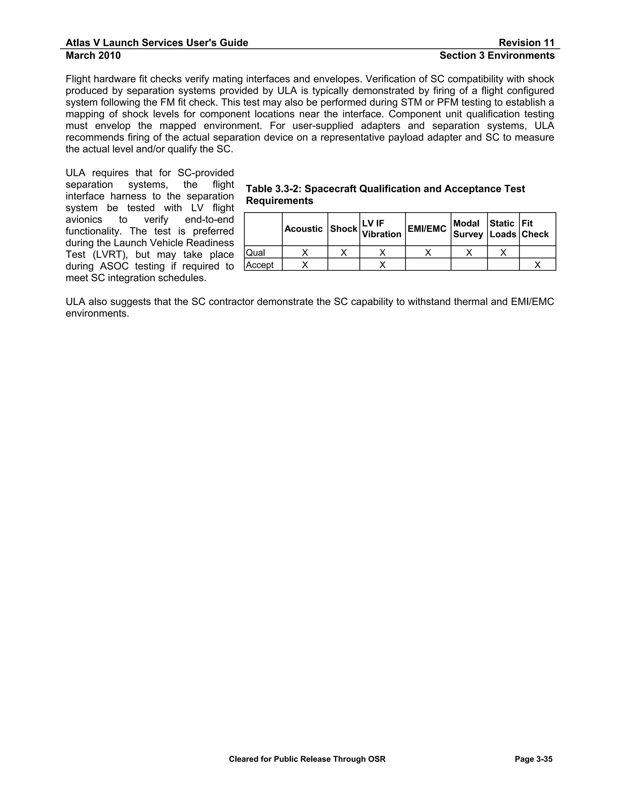
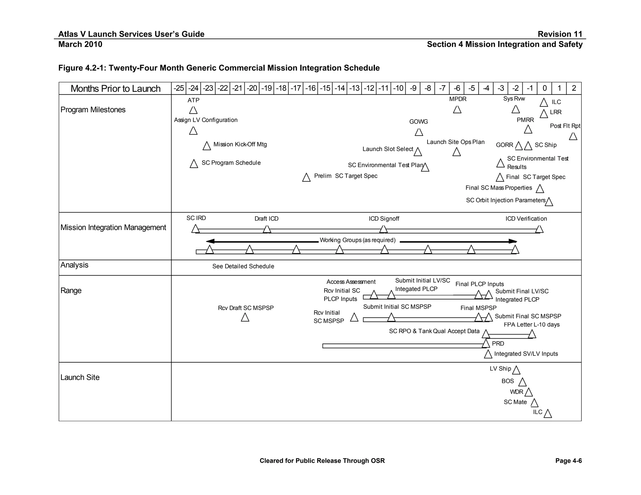
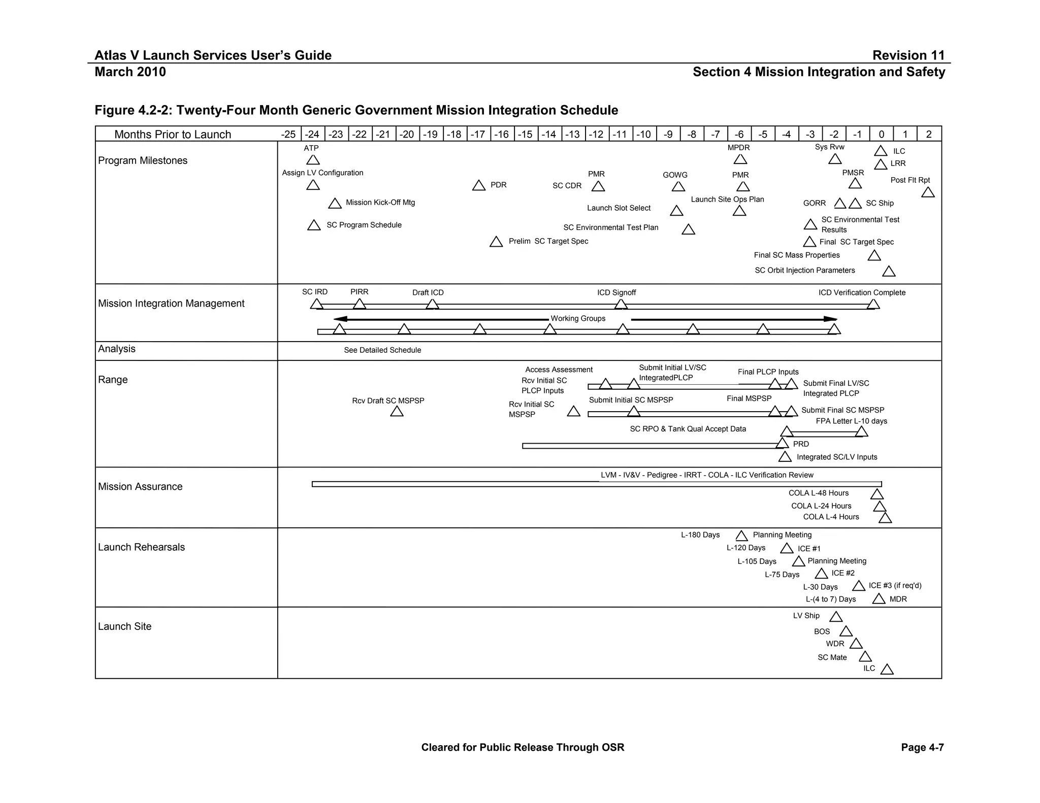
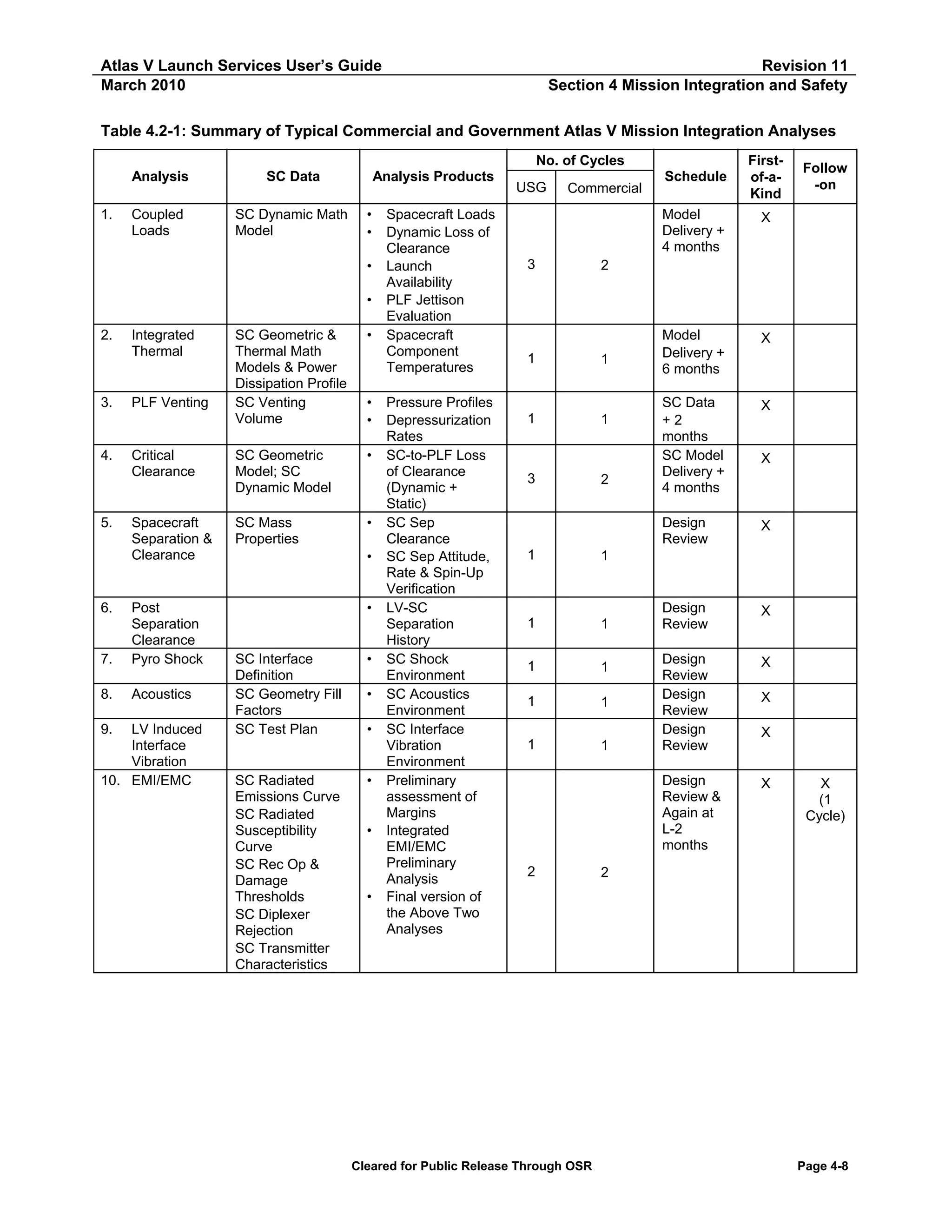
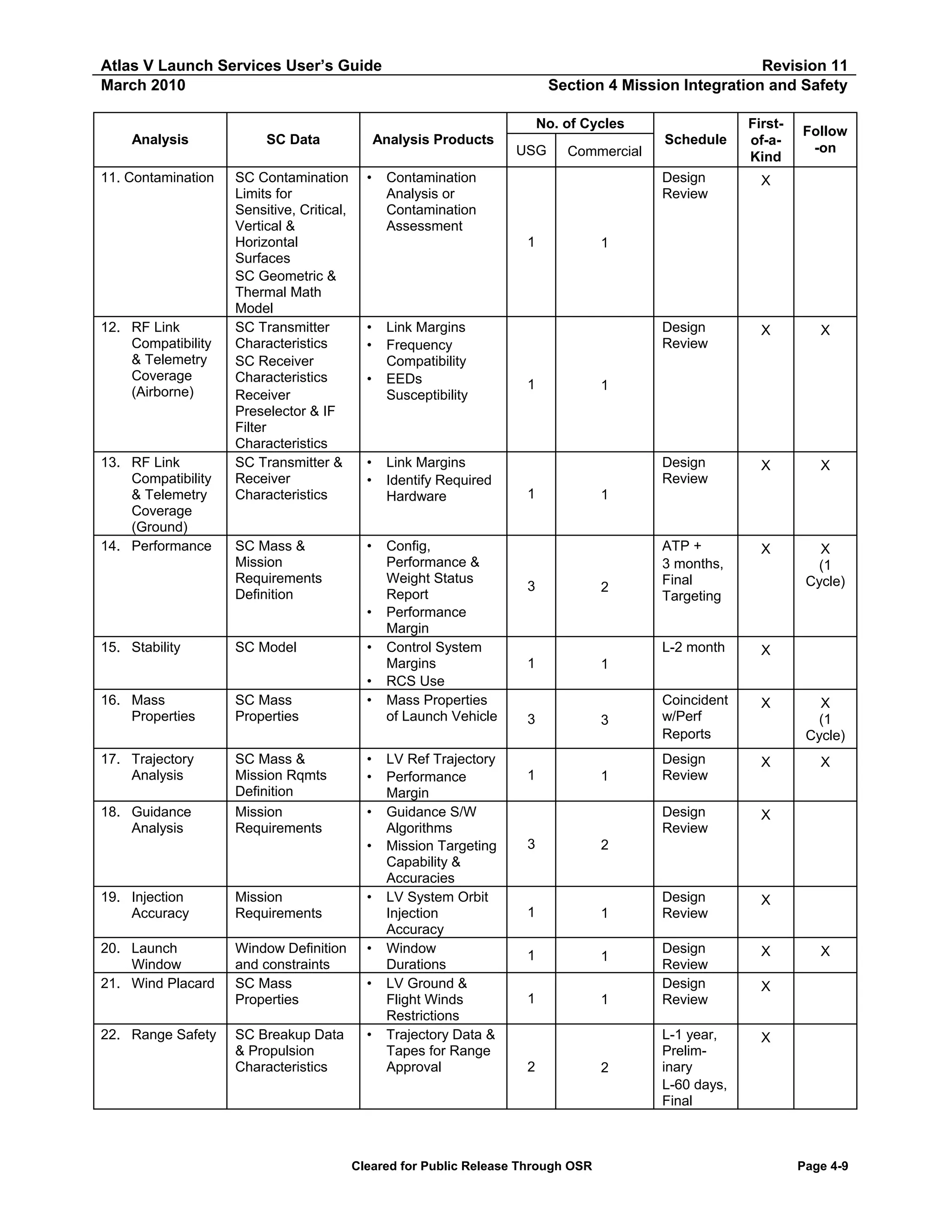
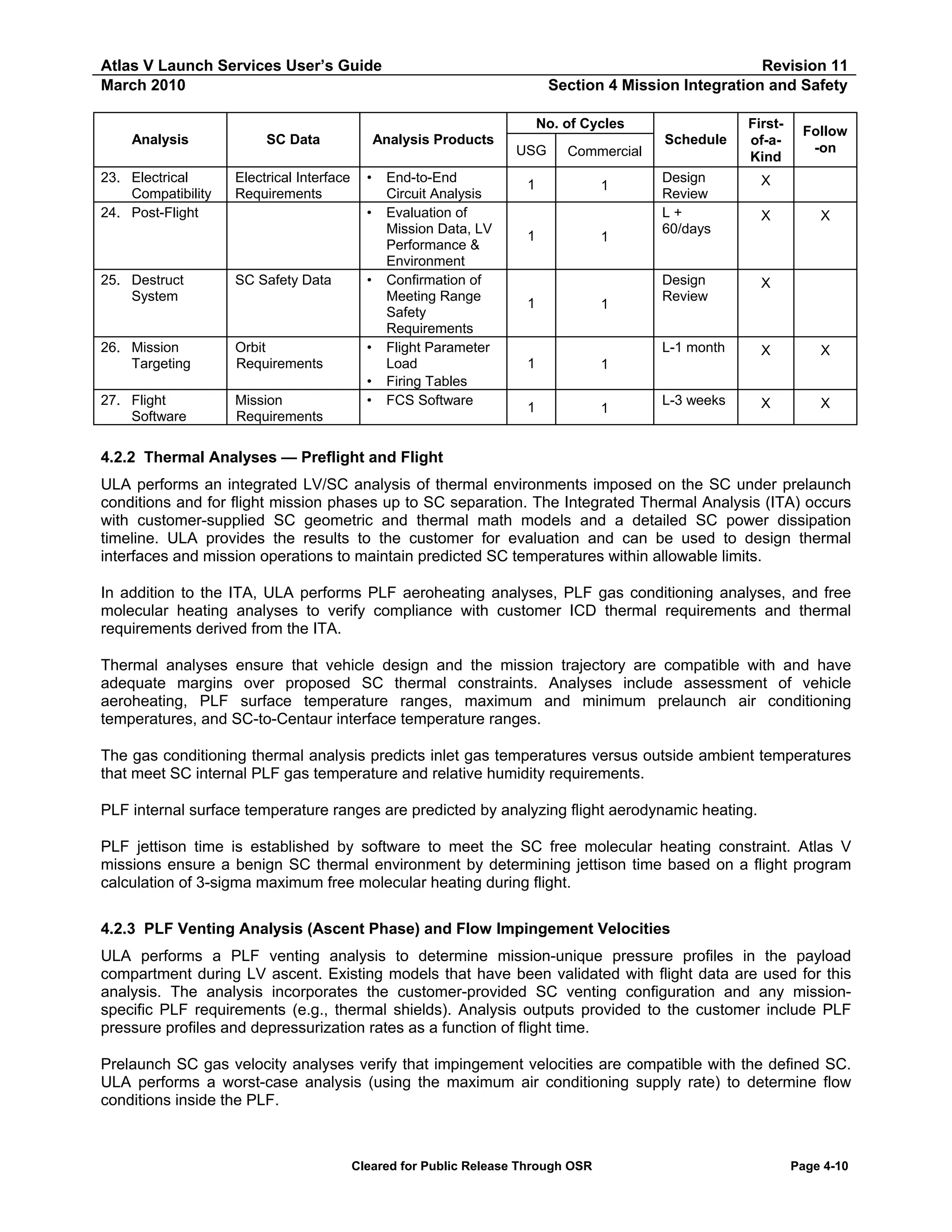
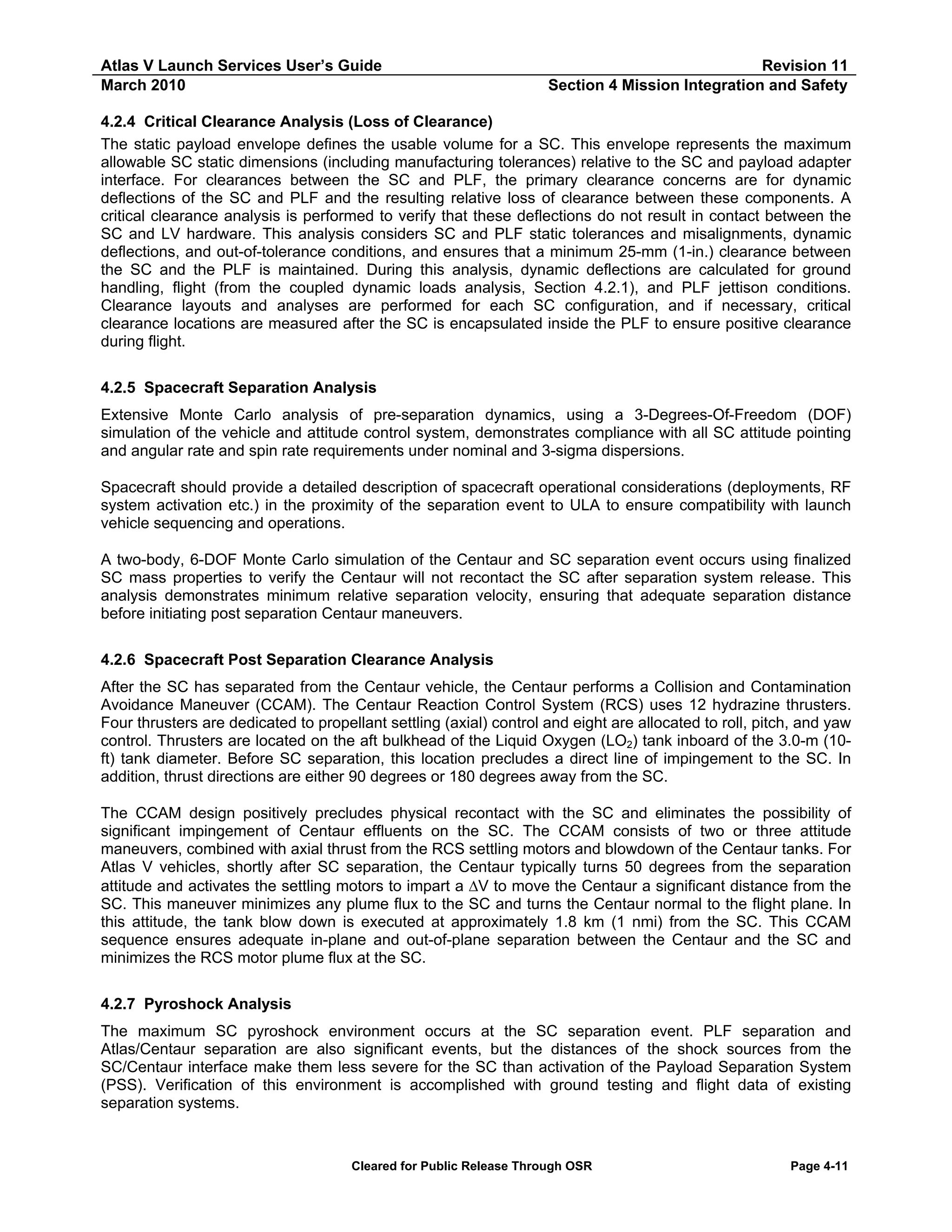
![Atlas V Launch Services User’s Guide
March 2010
Revision 11
Section 4 Mission Integration and Safety
4.3 RANGE AND SYSTEM SAFETY INTERFACES
4.3.1 Requirements and Applicability
To launch from either Cape Canaveral Air Force Station (CCAFS), FL, or Vandenberg Air Force Base
(VAFB), CA, LV/SC design and ground operations must comply with applicable launch site Range Safety
regulations, USAF requirements concerning explosives safety, and U.S. consensus safety standards. In
addition, compliance with applicable facility safety policies is also required when using SC processing
facilities operated by Spaceport Systems International (SSI), Astrotech Space Operations Inc. (ASO), NASA,
or the USAF.
CCAFS and VAFB Range Safety organizations have regularly updated their safety requirements documents.
Effective 1 July 2004, the single safety document for both CCAFS and VAFB (Eastern/Western Range
Regulation [EWR] 127-1) was replaced by AFSPCMAN 91-710. Existing LV and SC programs may not be
affected by the new AFSPCMAN 91-710 regulations unless required by the SC contracting agency. New
programs introduced after 1 July 2004 will negotiate applicable regulations with the Range Safety Office (45th
Space Wing for Eastern Range and 30th Space Wing for the Western Range). Earlier versions of Range
regulations may still apply to a given SC or mission, depending on when the SC bus was originally designed
and constructed and approved by the Eastern and/or Western Range Safety organizations.
Applicable safety compliance documents are determined during negotiations with Range Safety, ULA, and
the SC at the outset of the mission integration process.
Other safety documents that may also apply to the launch site safety interface are:
1. Radiation Protection Program, 45 Space Wing Instruction 40-201
2. Air Force Manual (AFM) 91-201, Explosives Safety Standard
3. Air Force Regulation (AFR) 127-12, Air Force Occupational Safety, Fire Prevention, and Health Program
4. MIL-STD 1522A, Standard General Requirements for Safe Design and Operation of Pressurized Missile
and Space Systems
5. MIL-STD 1576, Electro-explosive Subsystem Safety Requirements and Test Methods for Space
Systems
6. NASA KHB 1710.2, KSC Safety Practices Handbook (for SC processed at Kennedy Space Center
facilities)
7. Atlas Launch Site Safety Manual / Launch Complex Safety Plan
8. Payload Processing Facility (PPF) Safety Manual (ex., Astrotech Space Operations, Facility Safety
Manual (SHI-ASO-M008 or SHI-ASO-M0011))
At the start of the safety integration process (Section 4.3.2), Range Safety documents applicable to SC
design and ground processing operations will be determined. Safety requirements applicable to new designs
and ground processing operations will be reviewed and tailored for specific SC and mission applications.
ULA System Safety engineers will evaluate mission-specific SC designs and ground processing operations
and provide guidance for successful completion of the Range review and approval process. Should areas of
noncompliance be identified, ULA will evaluate each area and as appropriate, provide guidance for
resolution of specific noncompliance items while still meeting the intent of the applicable safety requirements.
For commercial programs, ULA as required, will act as the SC contractor’s liaison and facilitate interface
activities with the launch site Range Safety Office.
Cleared for Public Release Through OSR
Page 4-17](https://image.slidesharecdn.com/atlasvusersguide2010-140220084057-phpapp02/75/Atlas-v-usersguide2010-201-2048.jpg)
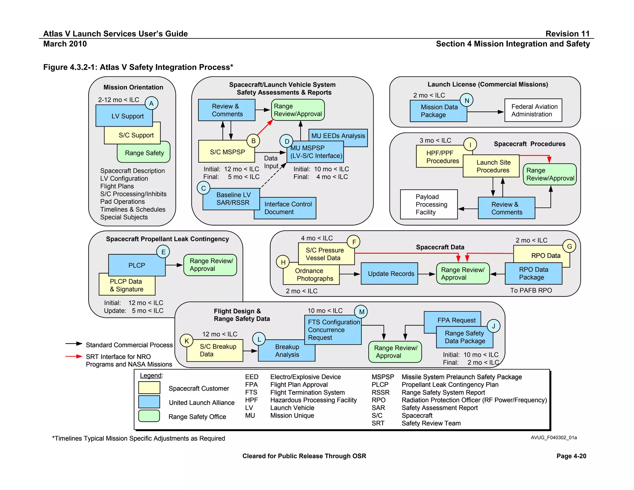
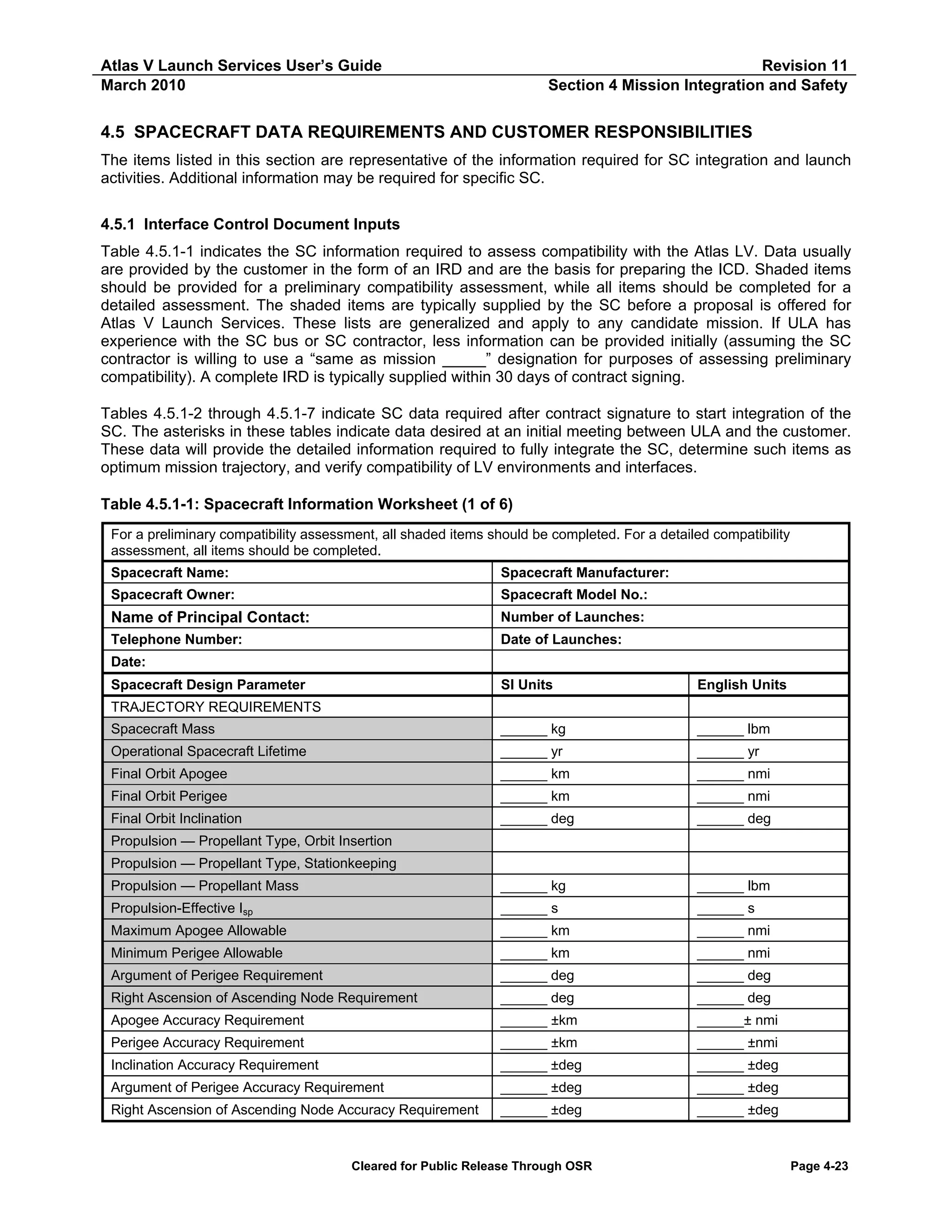
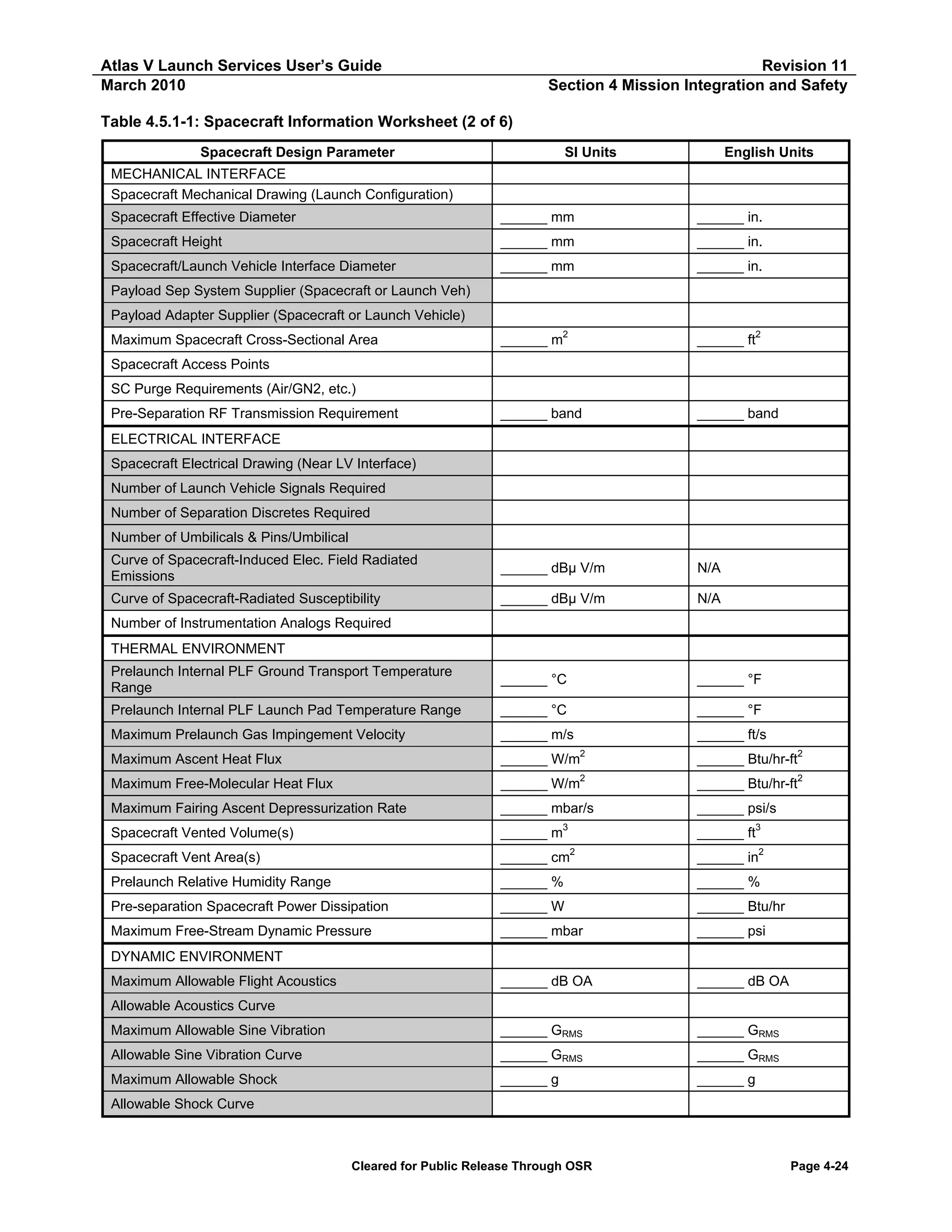
![Atlas V Launch Services User’s Guide
March 2010
Revision 11
Section 4 Mission Integration and Safety
Table 4.5.1-1: Spacecraft Information Worksheet (3 of 6)
Spacecraft Design Parameter
SI Units
English Units
DYNAMIC ENVIRONMENT CONTINUED
Maximum Acceleration (Static + Dynamic) Lateral
______ g
______ g
Maximum Acceleration (Static + Dynamic) Longitudinal
______ g
______ g
Fundamental Natural Frequency — Lateral
______ Hz
______ Hz
Fundamental Natural Frequency — Longitudinal
______ Hz
______ Hz
Cg—Thrust Axis (Origin at Separation Plane)
______ mm
______ in.
Cg — Y Axis
______ mm
______ in.
Cg — Z Axis
______ mm
______ in.
Cg Tolerance — Thrust Axis
______ ±mm
______ ±in.
Cg Tolerance — Y Axis
______ ±mm
______ ±in.
Cg Tolerance — Z Axis
______ ±mm
______ ±in.
Fundamental Natural Frequency — Longitudinal
______ Hz
______ Hz
Cg — Thrust Axis (Origin at Separation Plane)
______ mm
______ in.
PROPULSION SYSTEM 1
Propellant Type
Propellant Mass, nominal
______ kg
______ lbm
Propellant Fill Fraction
______ %
______ %
Propellant Density
______ kg/m3
______ lbm/ft3
______ mm
______ in
______ m3
______ ft3
3
______ ft3
Propellant Tank Material
Propellant Tank Location (SC Coordinates)
Station Azimuth
Diameter
Shape
Internal Volume
Capacity
______ m
Internal Description
Operating Pressure — Flight
______ kg/mm2
______lb/in2
Operating Pressure — Ground
______ kg/mm2
______lb/in2
Design Burst Pressure — Calculated
______ kg/mm2
______lb/in2
Proof Pressure — Test
______ kg/mm2
______lb/in2
Actual Burst Pressure — Test
______ kg/mm2
______lb/in2
Pressure When ULA Personnel are Exposed
______ kg/mm2
______lb/in2
______ kg
______ lbm
Factor of Safety (Design Burst/Ground Maximum Expected
Operating Pressure [MEOP])
Number of Vessels Used
PRESSURIZED TANK 1
Purpose
Vessel Contents
Tank Material
Capacity — Launch
Cleared for Public Release Through OSR
Page 4-25](https://image.slidesharecdn.com/atlasvusersguide2010-140220084057-phpapp02/75/Atlas-v-usersguide2010-209-2048.jpg)
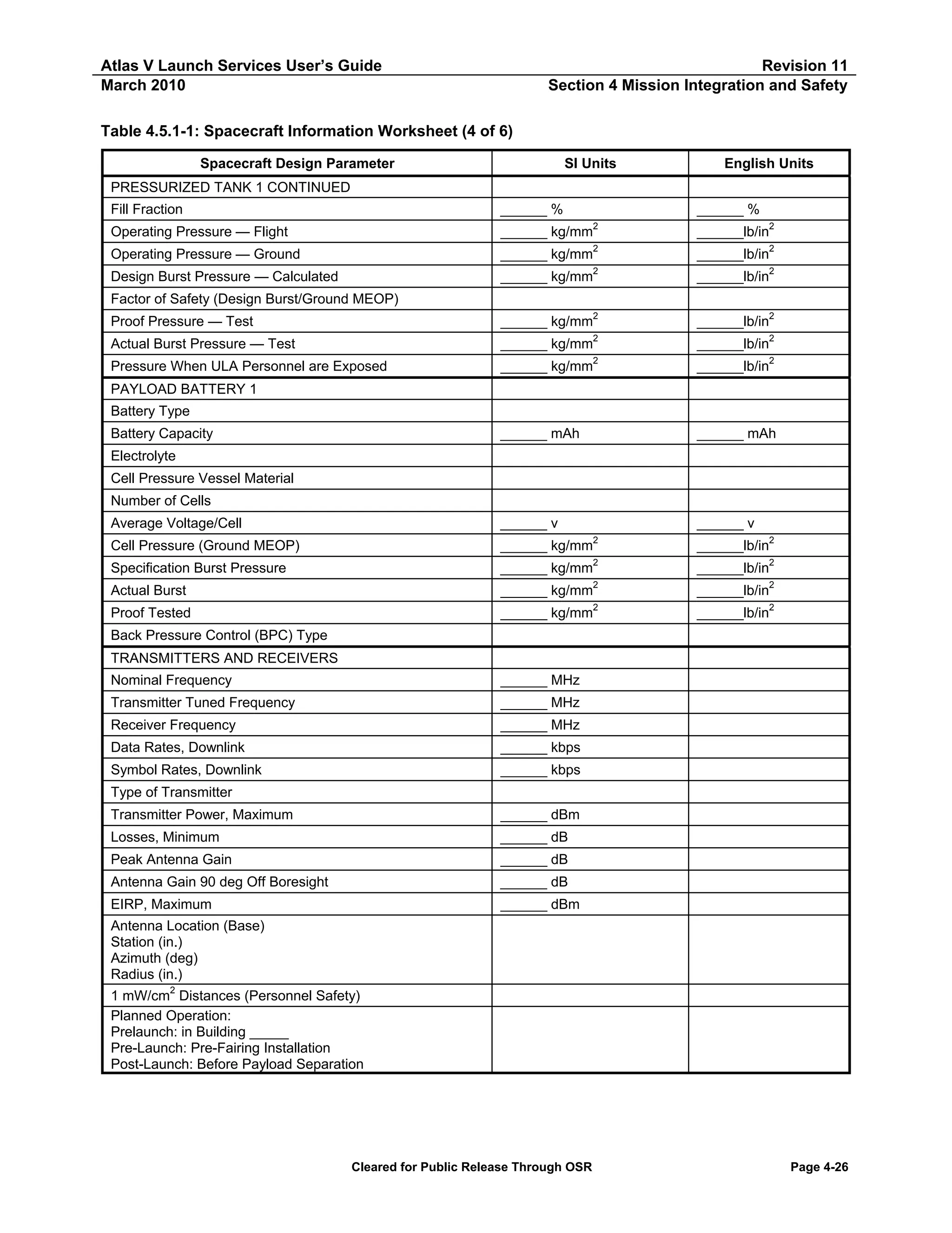
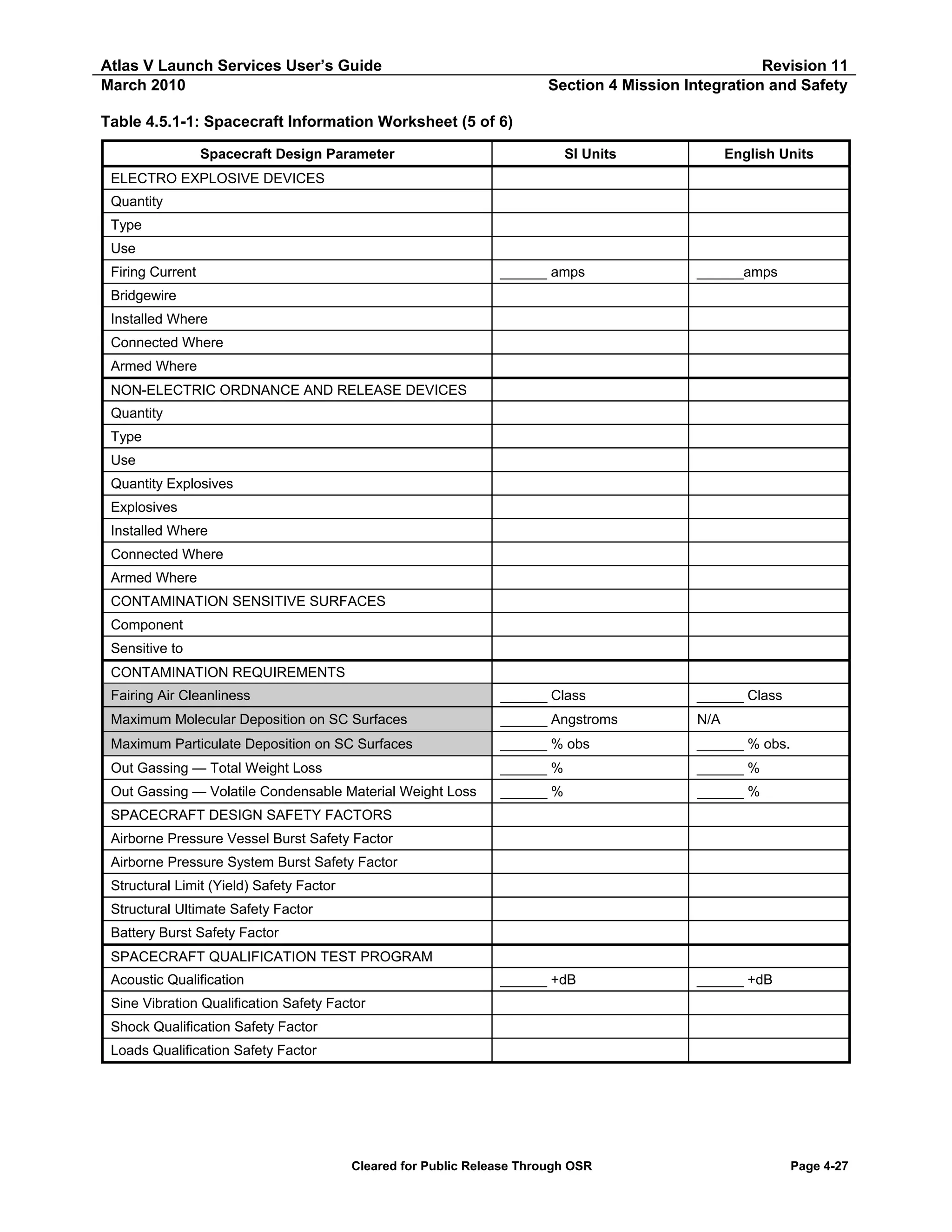
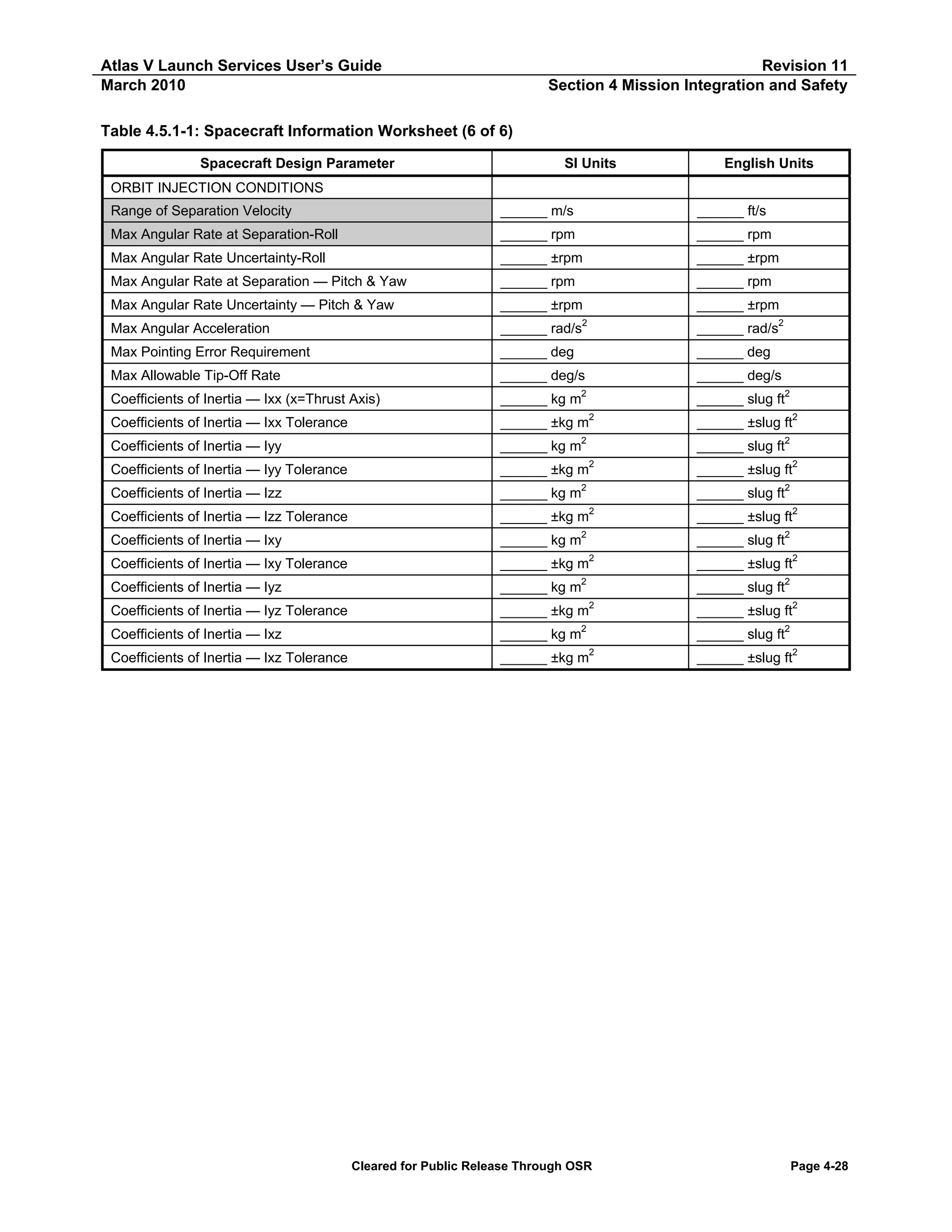
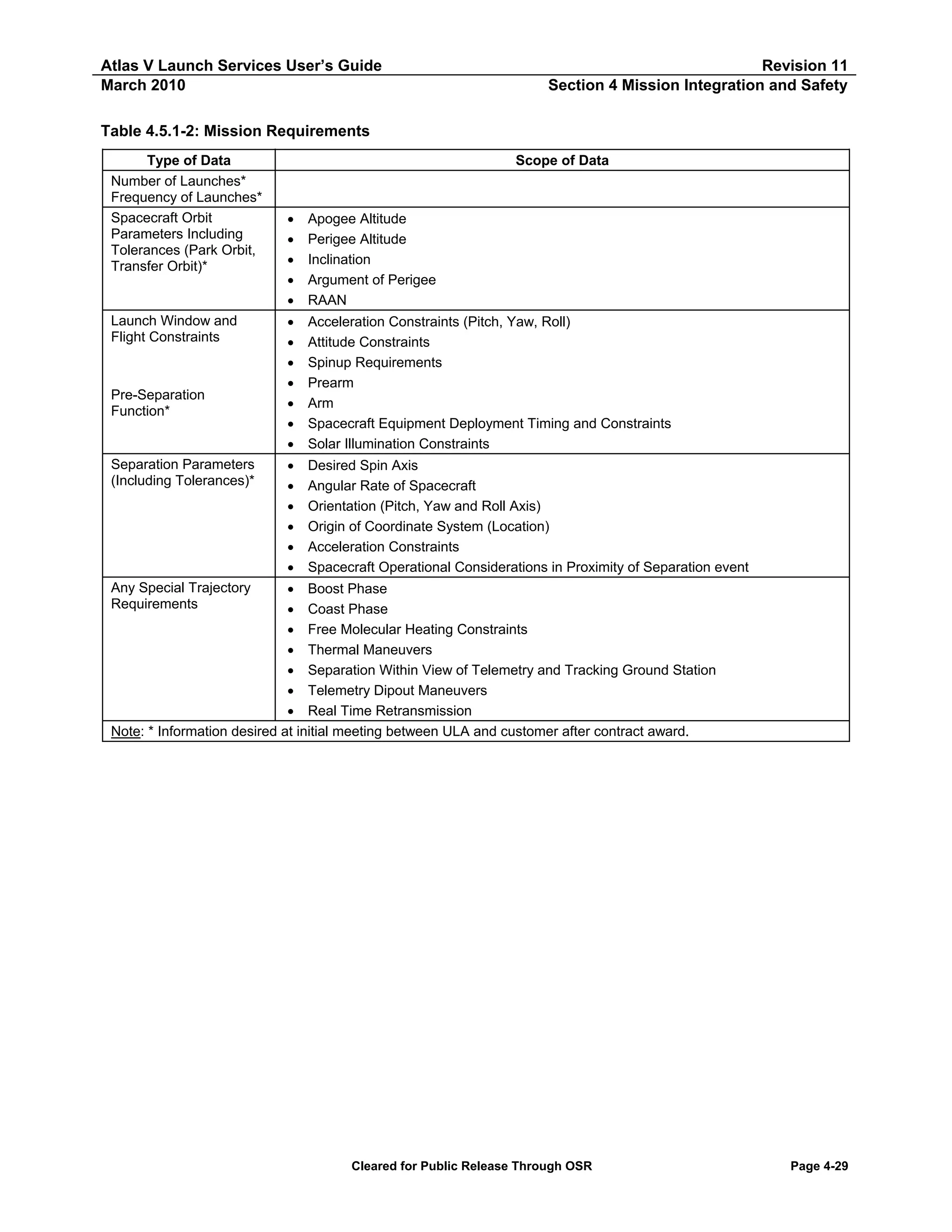
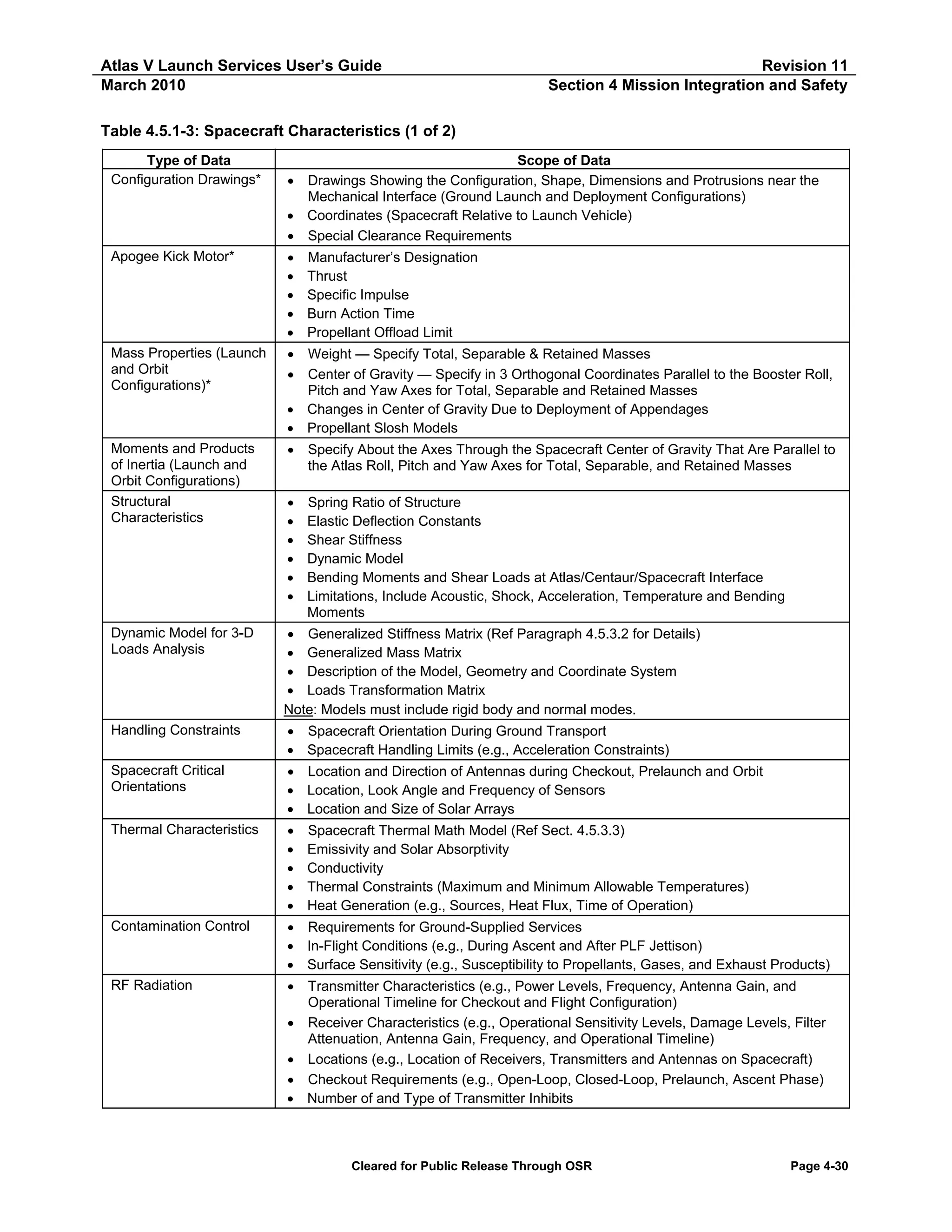
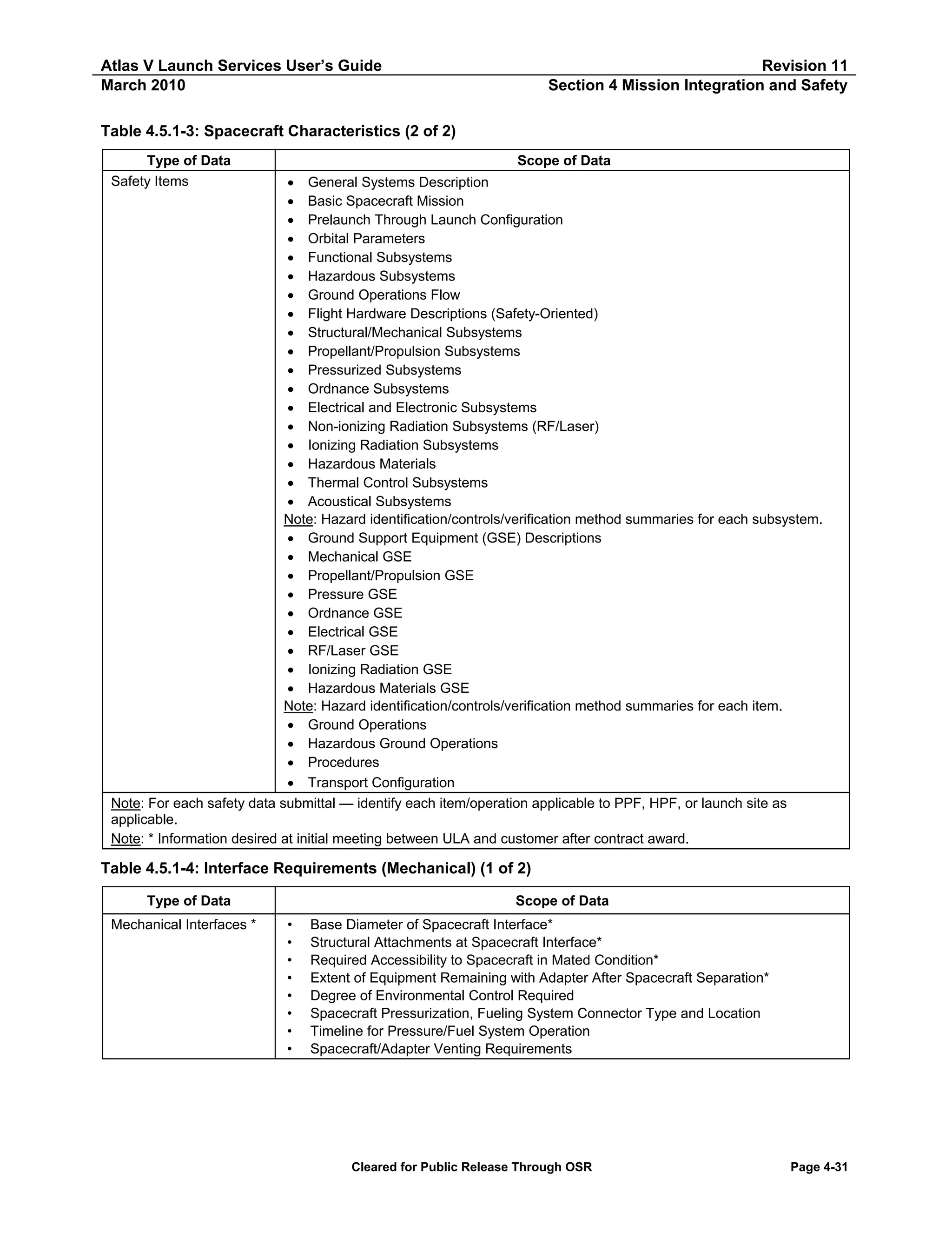
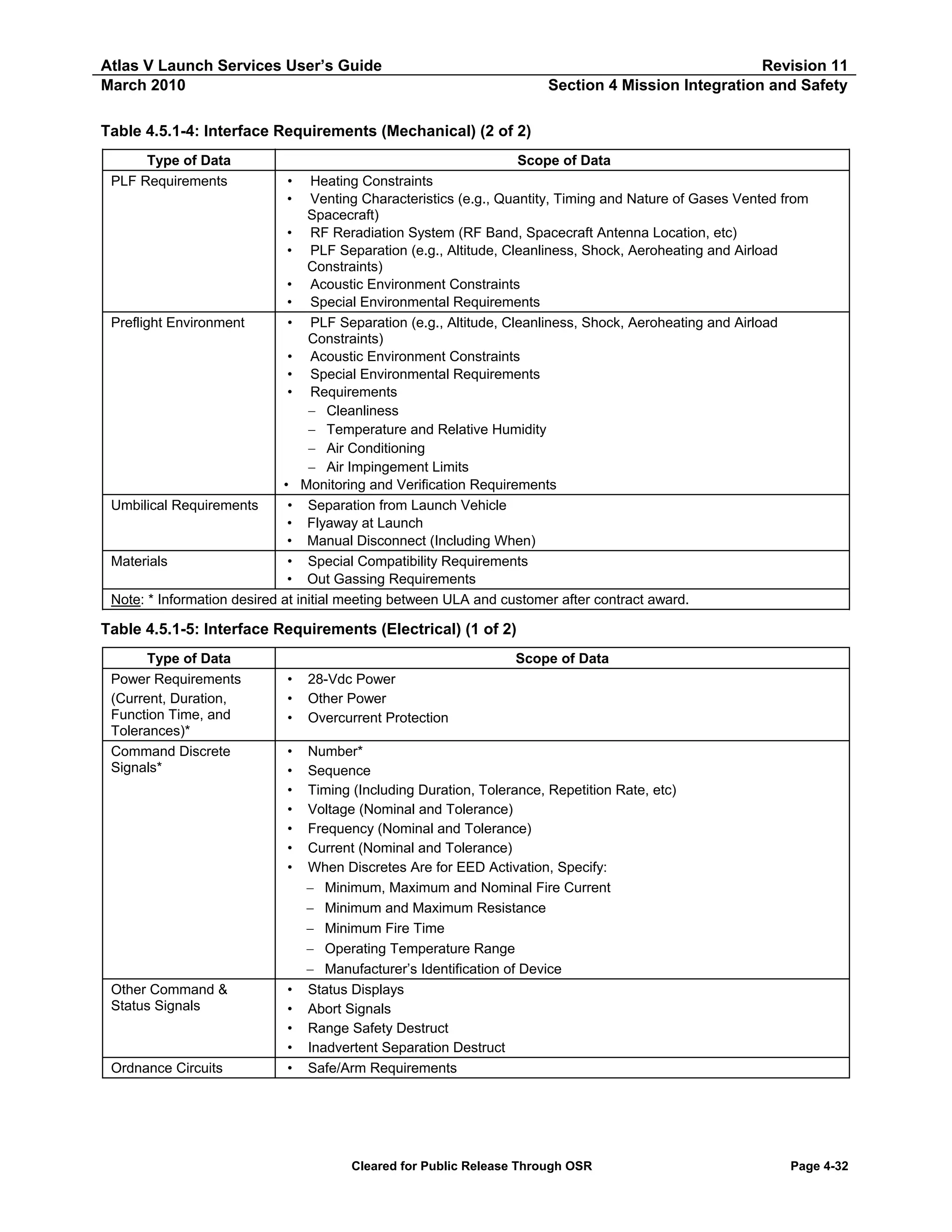
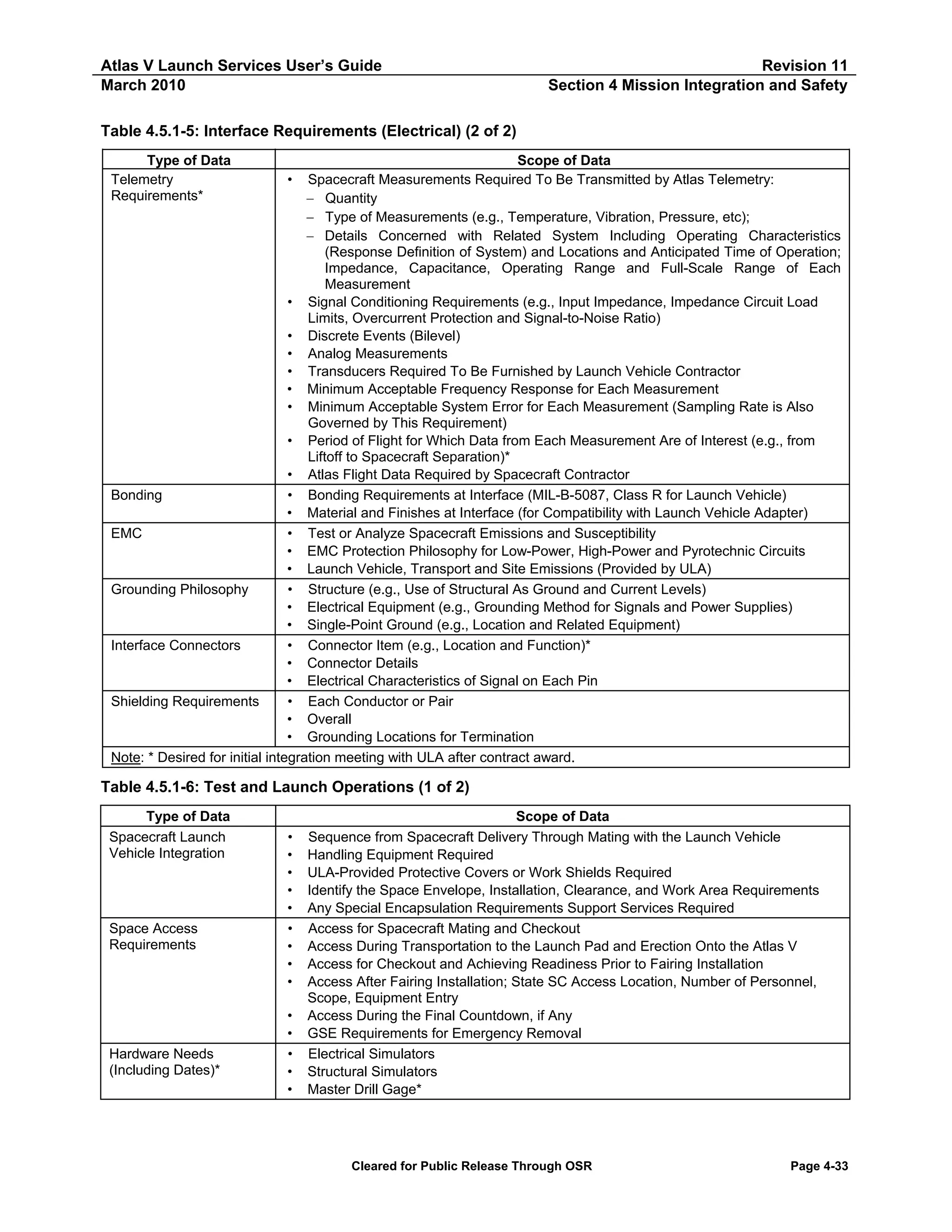
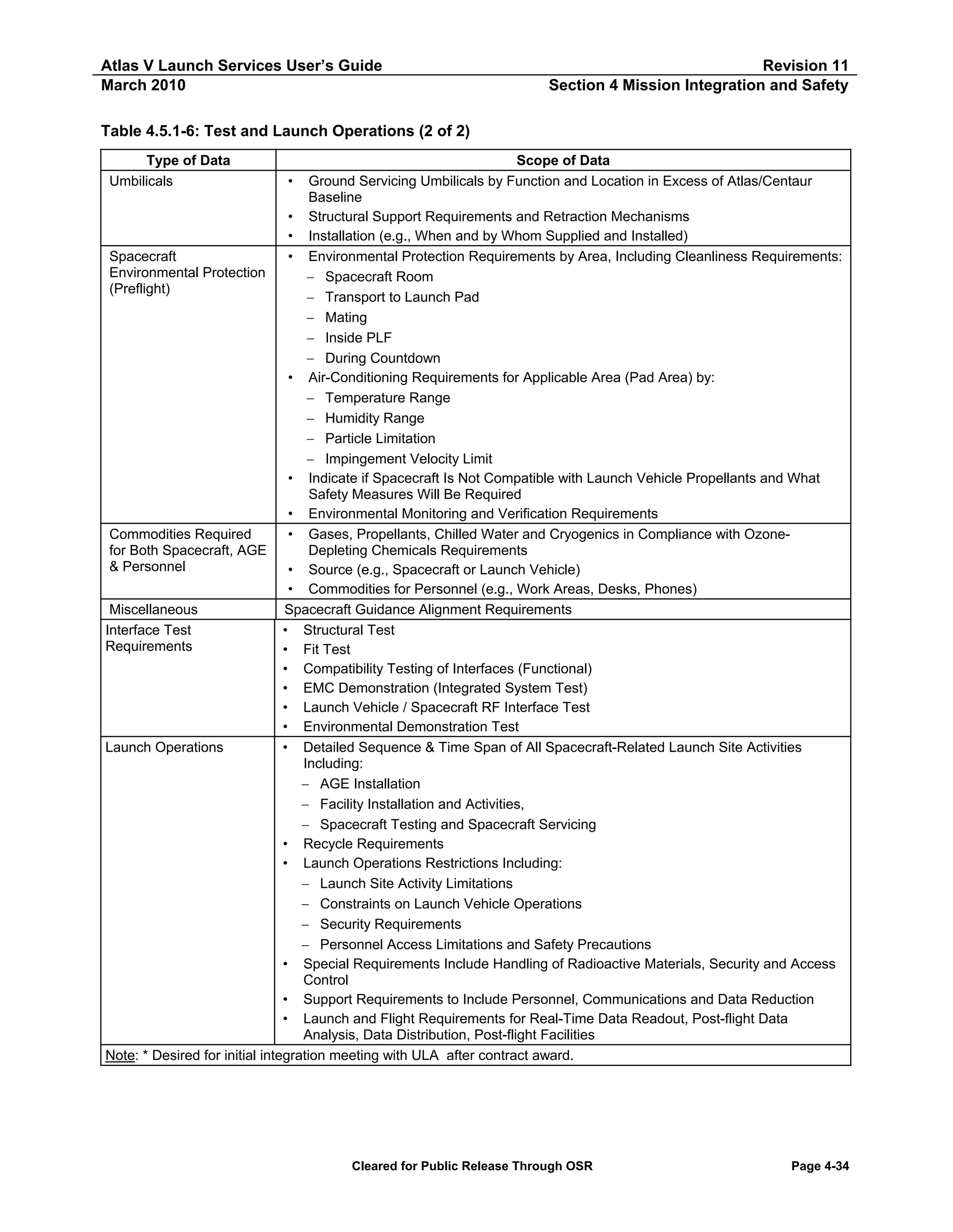
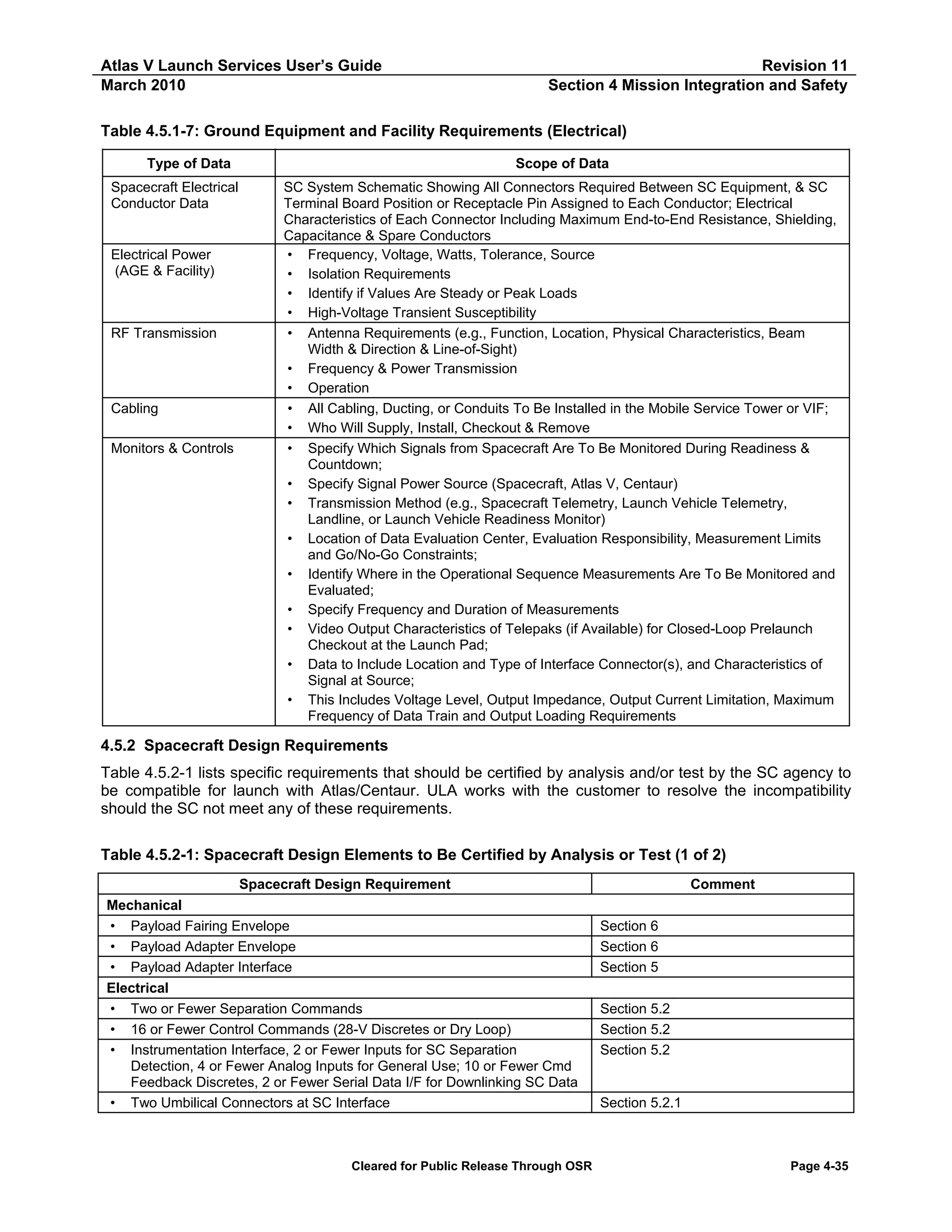
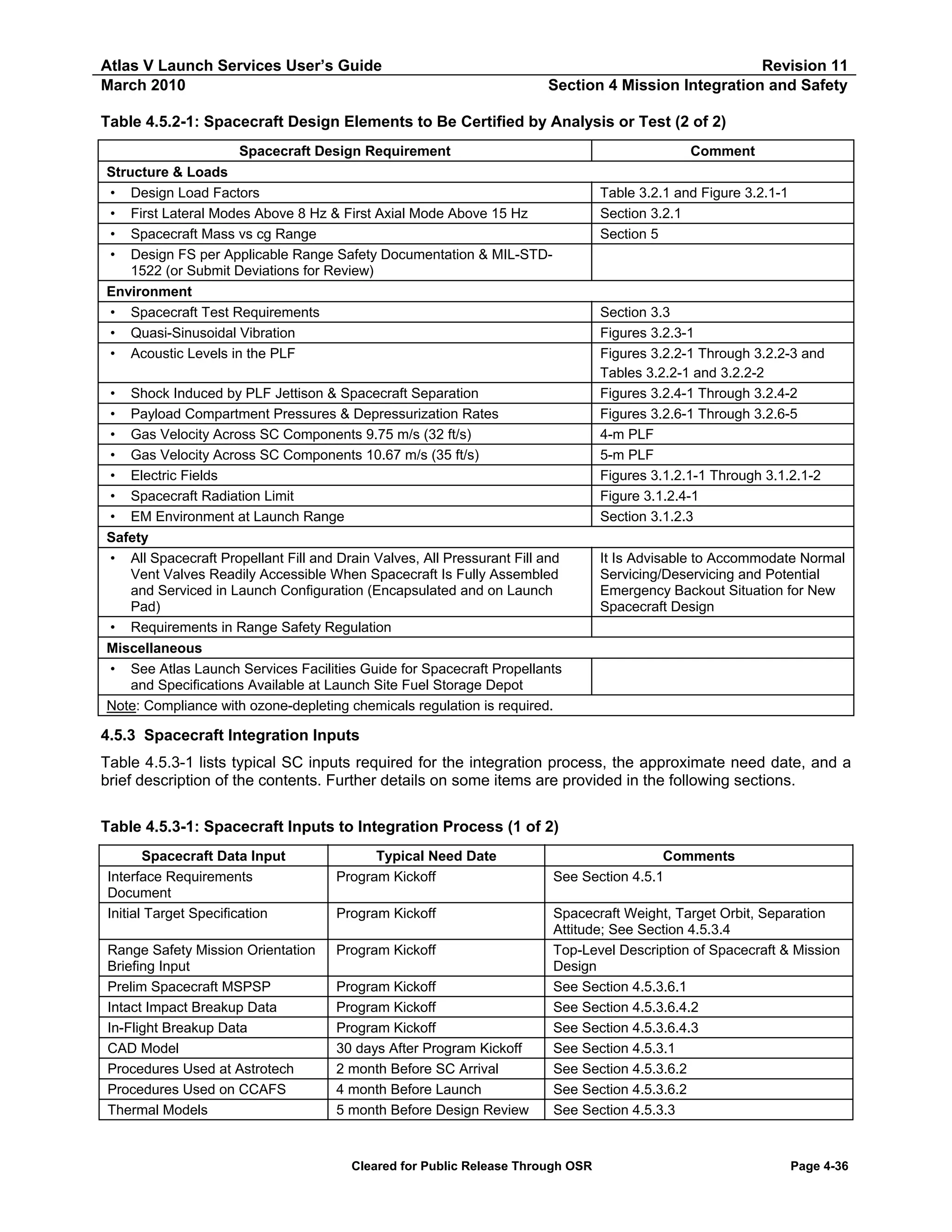
![Atlas V Launch Services User’s Guide
March 2010
Revision 11
Section 4 Mission Integration and Safety
Table 4.5.3-1: Spacecraft Inputs to Integration Process (2 of 2)
Spacecraft Data Input
Preliminary Launch Windows
Coupled Loads Model
Spacecraft EMI/EMC Cert Letter
Spacecraft EED Analysis
Final Target Specification
Typical Need Date
6 month Before Design Review
6 month Before Design Review
6 month Before Launch
6 month Before Launch
90 days Before Launch
Spacecraft Environment
Qualification Test Reports
As Available
Comments
Support Thermal Analysis; See Section 4.5.3.3
See Section 4.5.3.2
See Section 4.5.3.5
See Section 4.5.3.5
Date Depends on Mission Design;
See Section 4.5.3.4
See Table 4.5.2-1 for Environment
Qualification Requirements
4.5.3.1 Computer-Aided Design Data Transfer Requirements
The Atlas V program uses both the UNIX- and MS Windows-based operating systems and uses the
Parametric Technology Corporation (PTC) Pro-Engineer (Pro-E) CAD program. CAD data should be
provided according to this specified software format. When feasible, ULA prefers to receive solid or surface
model data translated through the Standard for the Exchange of Product Model Data (STEP) converter. An
alternative to this would be the equivalent in an Initial Graphics Exchange Specification (IGES) 4.0 or higher
file format. Wireframe geometry may be included with the solid or surface model transfer.
4.5.3.1.1
Prerequisites to Data Transfer
The following criteria should be met by the SC contractor before transferring CAD data:
1. Verify that the data files contain the desired results by reading them back onto the originating CAD
system from the source file before transmittal to ULA.
2. Provide entire representation of all external SC components for best integration to the Atlas LV. All
internal structures are not necessary and should be removed from model transfer files.
3. Write out the Pro-E, STEP, and/or IGES model files as assemblies and not as a single part file. Ensure
that the total SC model transfer does not exceed 150 MB in an uncompressed file size.
4. Remove all non-essential geometry such as points, axis lines, and lines-of-action before creating the
data.
5. Ensure ITAR license agreements are met.
If feasible, the entire directory should be compressed and transferred as a single file using (UNIX) Tar (tar
cvf/dev/rmt0 part name), or (Windows) “WinZip” or equivalent.
4.5.3.1.2
Data Transfer
Compact disk, DVD media, and/or a ULA-based electronic file server (i.e., iDM LiveLink or File Transfer
Protocol [FTP]) are the preferred transfer methods for all data files. An account can be established on a ULA
firewall server for electronic data transfers. An alternative method would involve the contractor providing
similar access to one of their systems via a temporary account. In either case, the transfer type should be set
to binary. If using an FTP server, proprietary or sensitive data should be encrypted using Pretty Good
Privacy (PGP) keys or equivalent. Because of security concerns, email transfers are not recommended at
this time. If CDROM, DVD or electronic transfer methods are not feasible, contact appropriate ULA
personnel listed in the Preface to provide a coordinated and acceptable method of data transfer.
The following information must be sent with the CAD data regardless of transfer method:
Cleared for Public Release Through OSR
Page 4-37](https://image.slidesharecdn.com/atlasvusersguide2010-140220084057-phpapp02/75/Atlas-v-usersguide2010-221-2048.jpg)
![Atlas V Launch Services User’s Guide
March 2010
Revision 11
Section 4 Mission Integration and Safety
1. SC models security status must be clearly marked and communicated (Proprietary Data, Third-Party
Proprietary, Non-public Space Vehicle Information [NPSVI], etc.)
2. Name and phone number of the contact person who is familiar with the model in case problems or
questions arise
3. SC axis and coordinate system
4. SC access requirements for structure not defined on CAD model (i.e. fill and drain valve locations)
5. Multiview plot or jpeg(s) file of model
6. Uudecode (UNIX-based) information, if applicable
4.5.3.2 Coupled-Loads Analysis Model Requirements
The customer-supplied dynamic mathematical model of the SC should consist of generalized mass and
stiffness matrices, and a recommended modal damping schedule. The desired format is Craig-Bampton,
constrained at the Centaur interface in terms of SC modal coordinates and discrete Centaur interface points.
The SC dynamic model should have an upper frequency cutoff of 90 to 100 Hz. The Output Transformation
Matrices (OTM) should be in the form that, when multiplied by the SC modal and interface generalized
coordinate responses, will recover the desired accelerations, displacements, or internal loads. One of the
OTMs should contain data that will allow calculation of loss of clearance between the payload fairing and
critical points on the SC. Typically, the size of the OTMs is 200 to 500 rows for accelerations, 50 to 200 rows
for displacements, and 300 to 1,000 rows for internal loads.
4.5.3.3 Spacecraft Thermal Analysis Input Requirements
SC geometric and thermal mathematical models are required to perform the integrated thermal analysis.
These models should be delivered electronically or on a computer diskette with printed listings of all the files.
The Geometric Mathematical Model (GMM) and Thermal Mathematical Model (TMM) size should be less
than 2,000 nodes/surfaces each.
The preferred GMM format is Thermal Desktop input format. Alternate formats are Thermal Radiation
Analysis System (TRASYS), TSS, or NEVADA input formats. The documentation of the GMM should include
illustrations of all surfaces at both the SC and component levels, descriptions of the surface optical
properties, and the correspondences between GMM and TMM nodes.
The preferred TMM format is System-Improved Numerical Differencing Analyzer (SINDA). The TMM
documentation should include illustrations of all thermal modeling; detailed component power dissipations for
prelaunch, ascent, and on-orbit mission phases; steady state and transient test case boundary conditions,
output to verify proper conversion of the input format to ULA analysis codes; maximum and minimum
allowable component temperature limits; and internal SC convection and radiation modeling.
In addition to the TMM and GMM, launch window open and close times for the entire year are required
inputs to the integrated thermal analysis.
4.5.3.4 Target Specifications
Target specifications normally include the final mission transfer orbit (apogee and perigee radii, argument of
perigee, and inclination), SC mass, and launch windows. The final target specification is due to ULA 90 days
before launch for missions incorporating Minimum Residual Shutdown (MRS) or In-Flight Retargeting (IFR),
and 60 days before launch for guidance commanded-shutdown GCS missions.
Cleared for Public Release Through OSR
Page 4-38](https://image.slidesharecdn.com/atlasvusersguide2010-140220084057-phpapp02/75/Atlas-v-usersguide2010-222-2048.jpg)
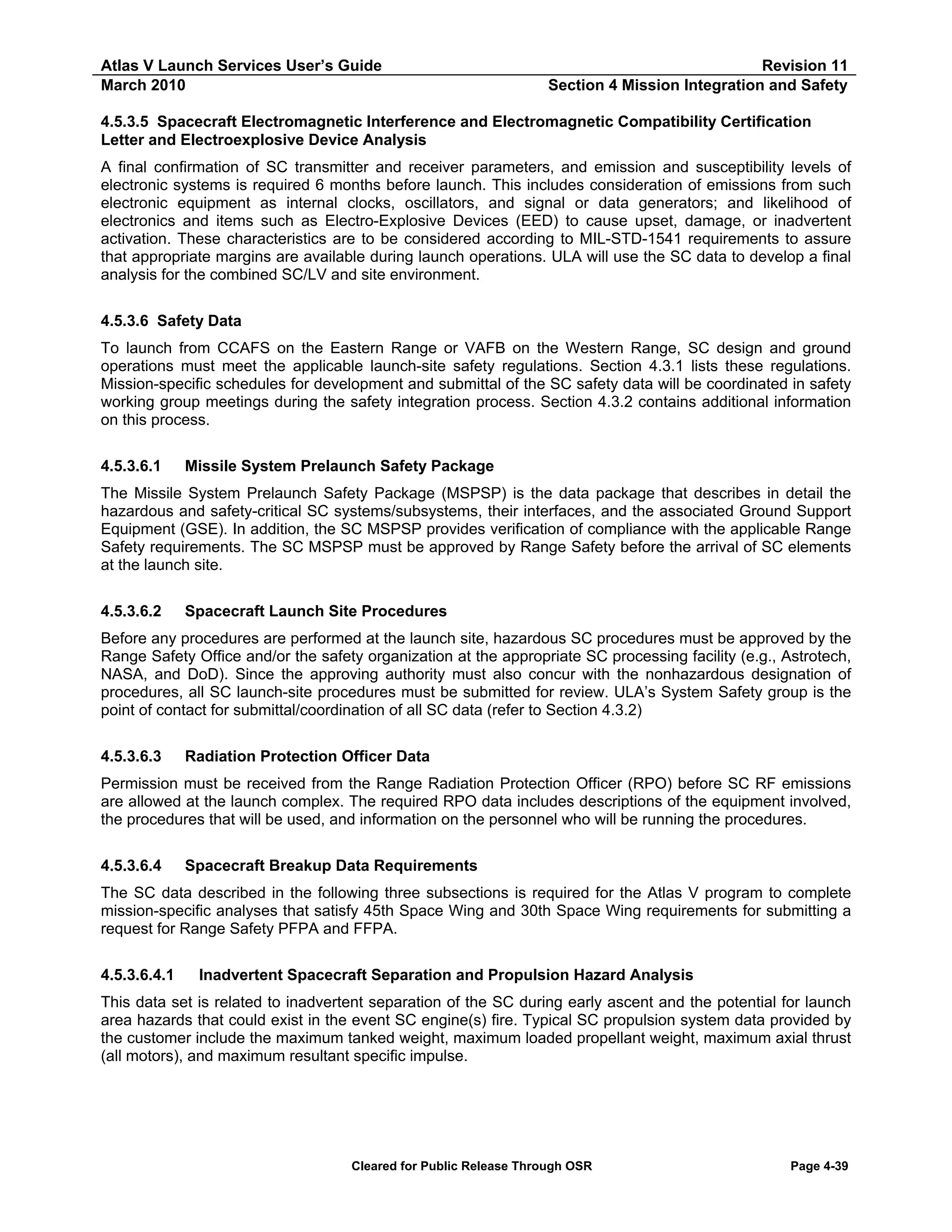
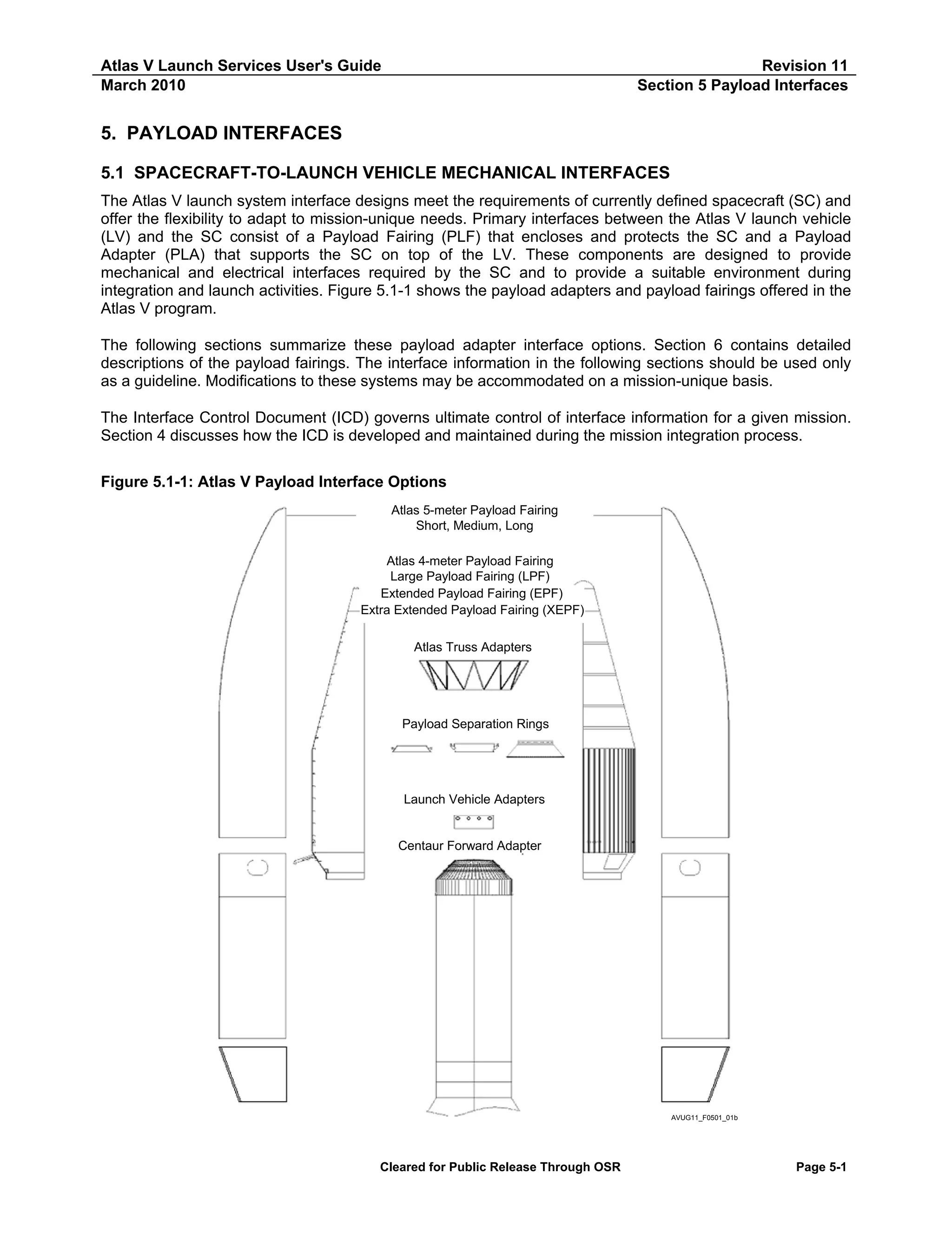
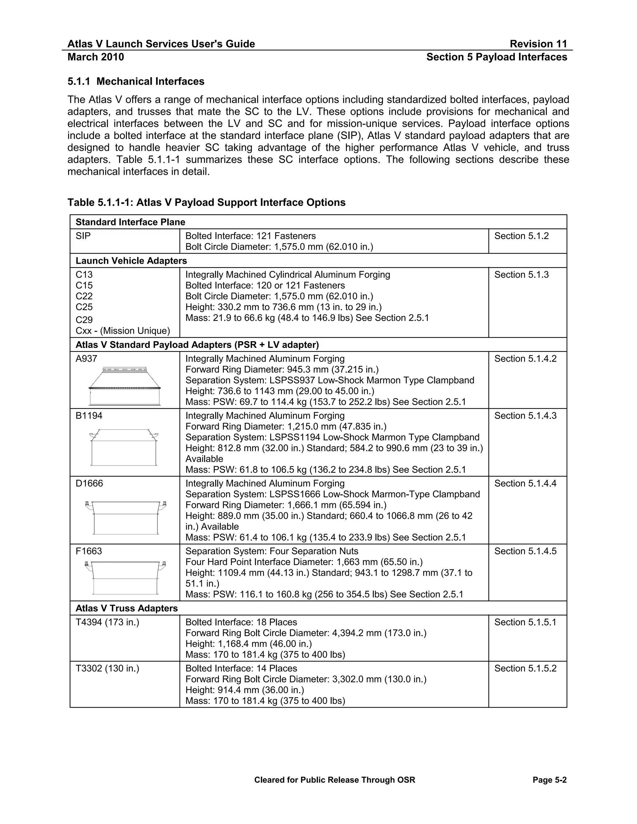
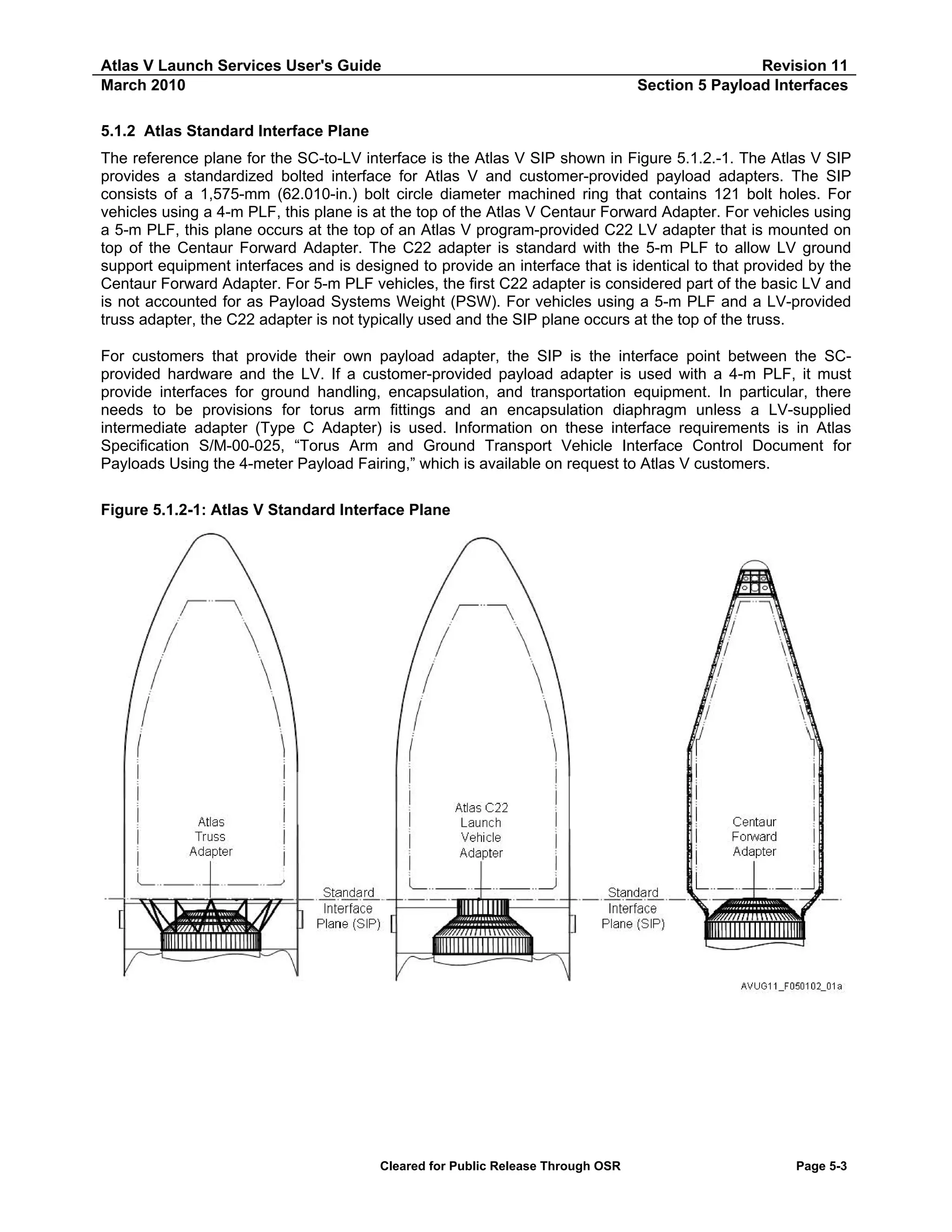
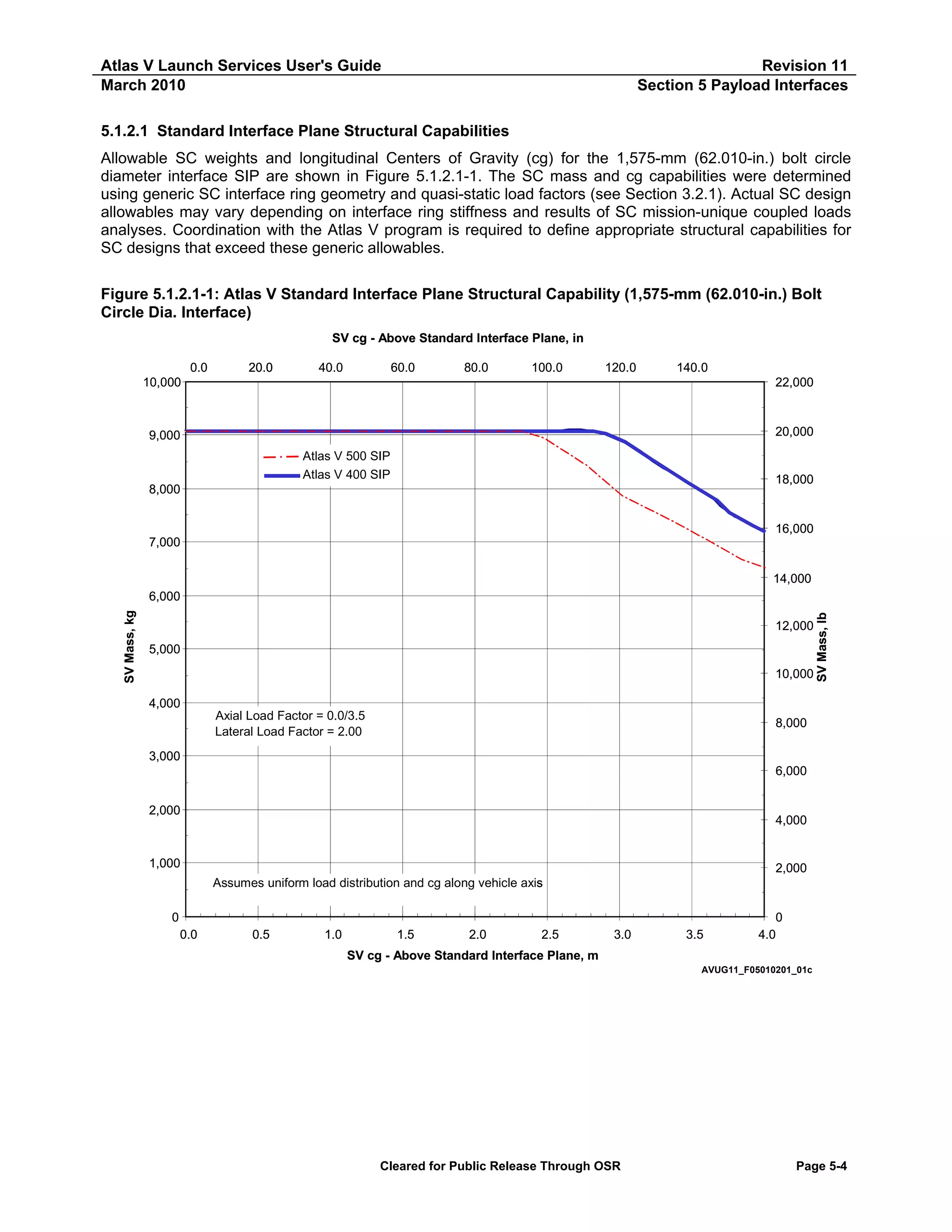
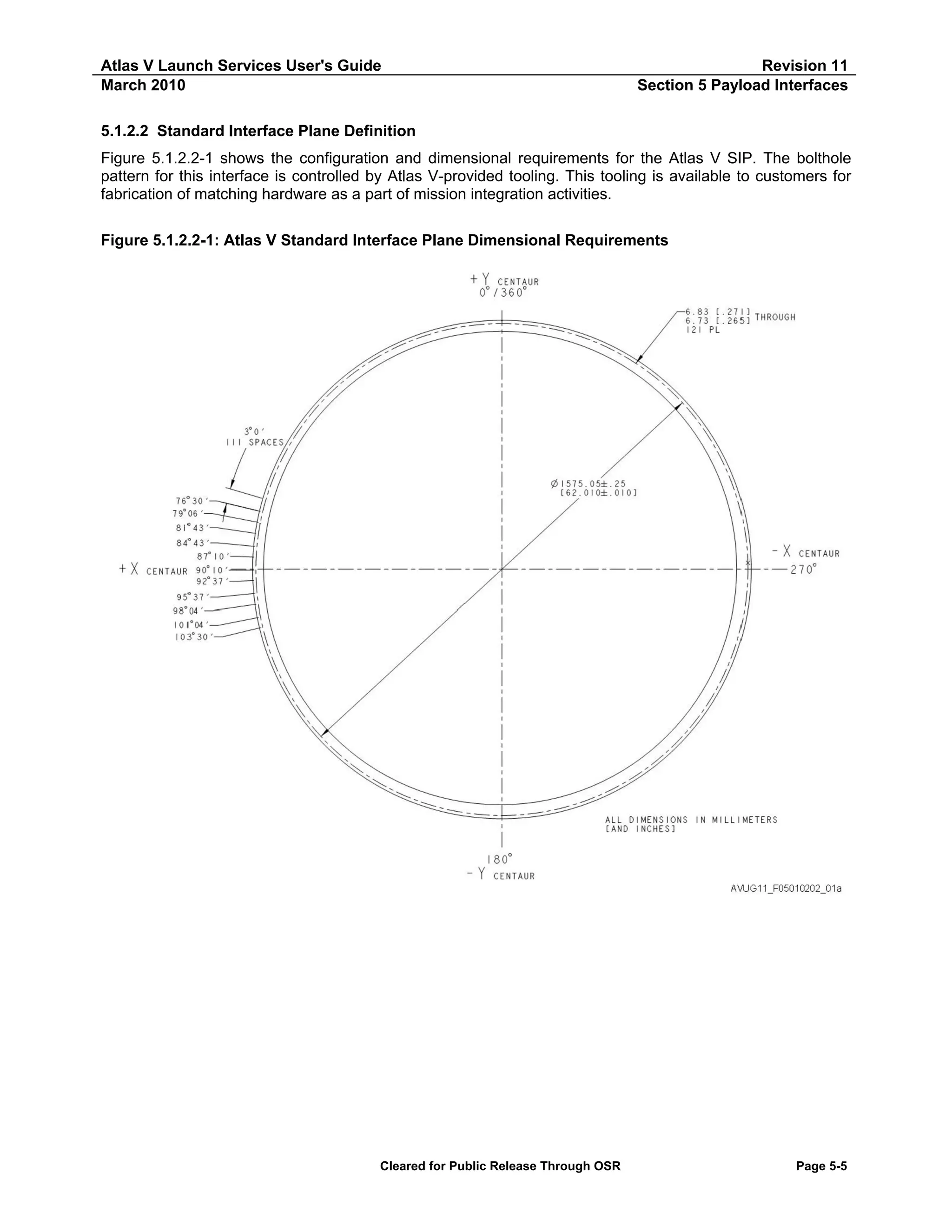
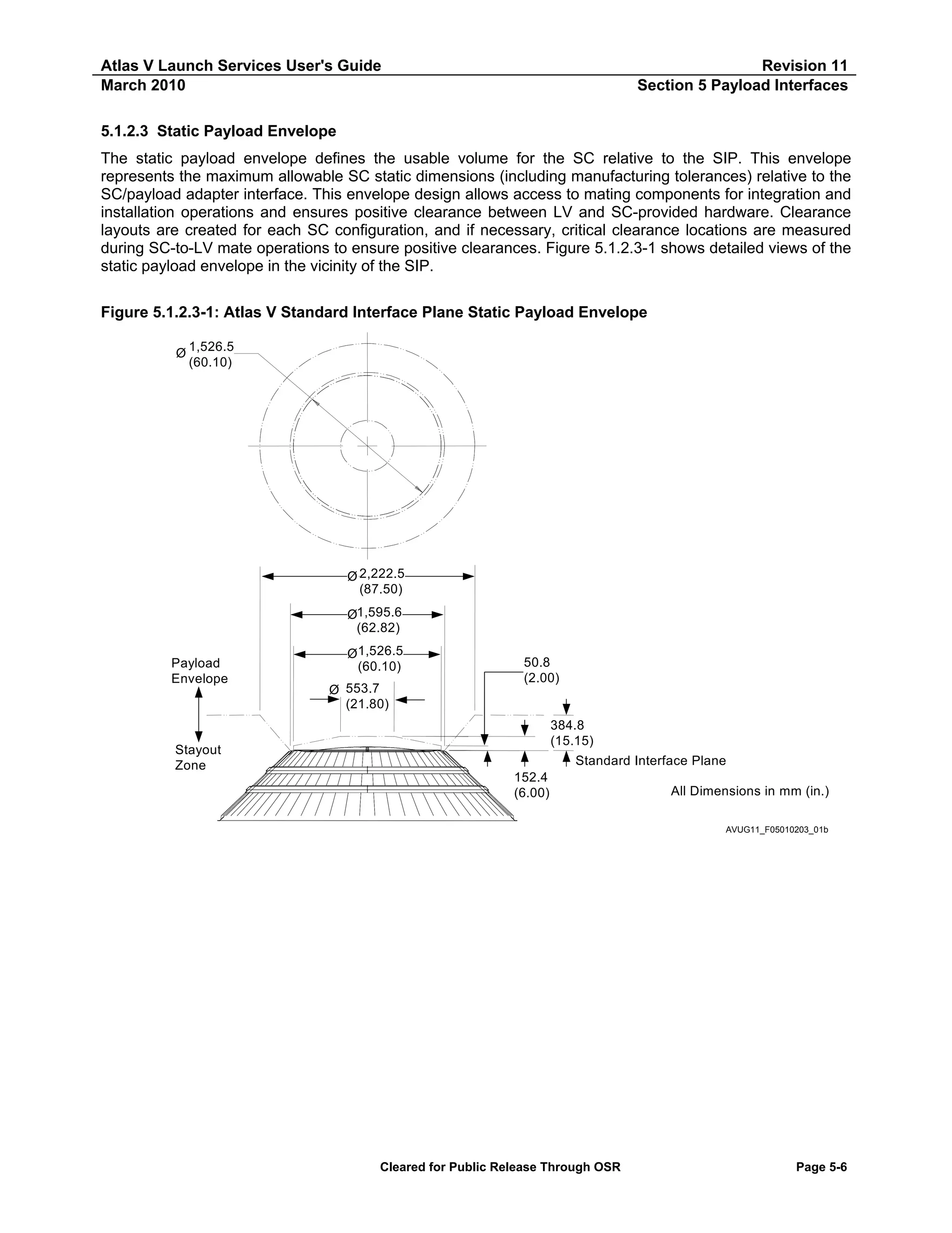
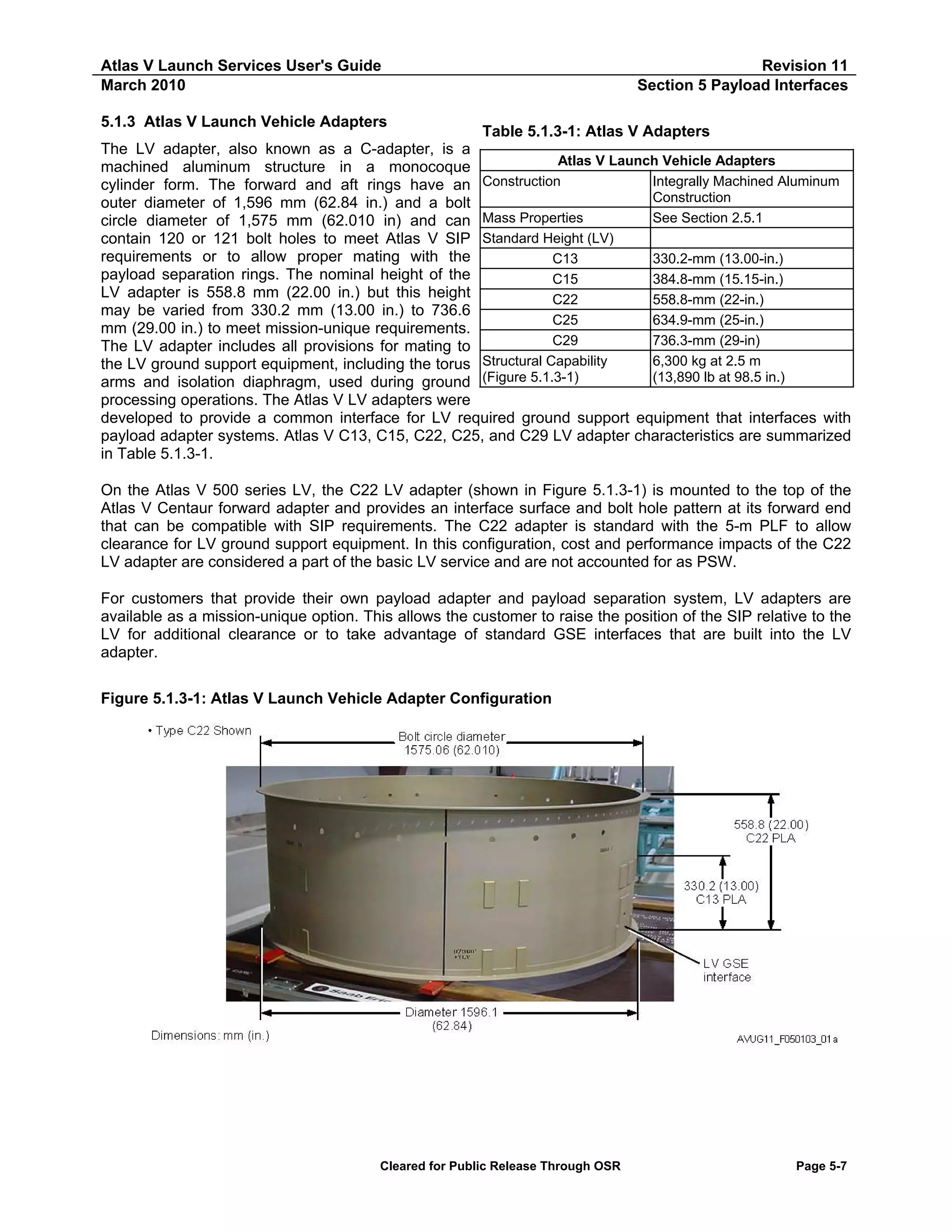
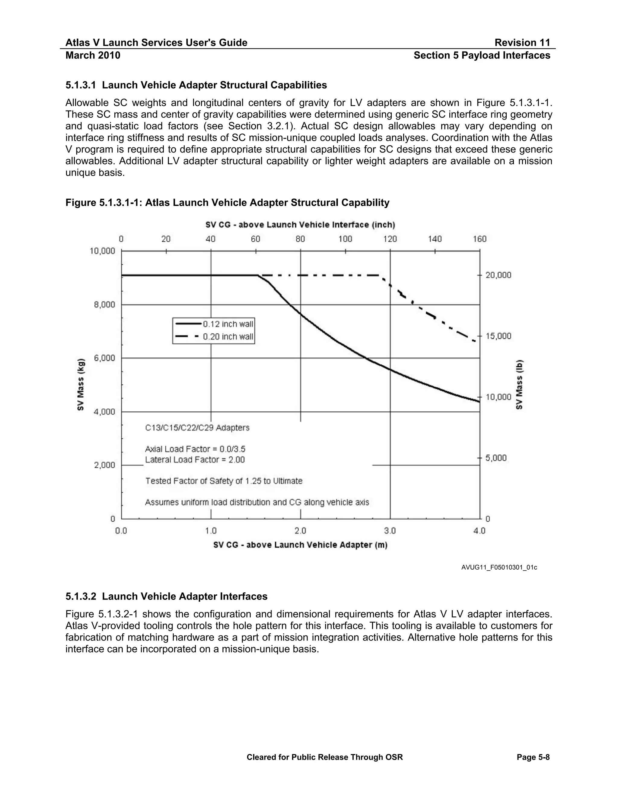
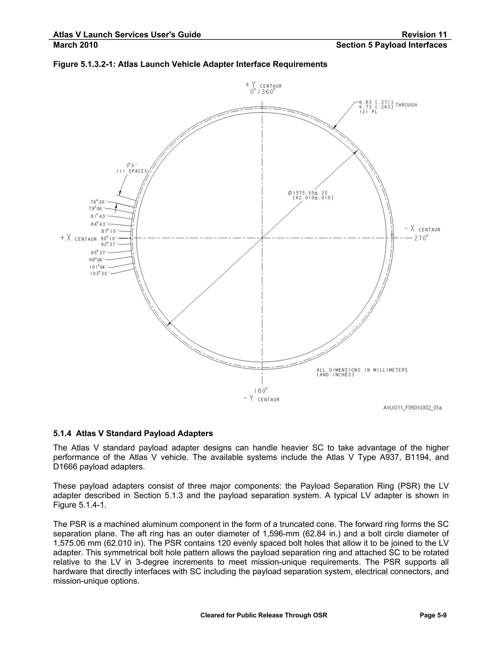
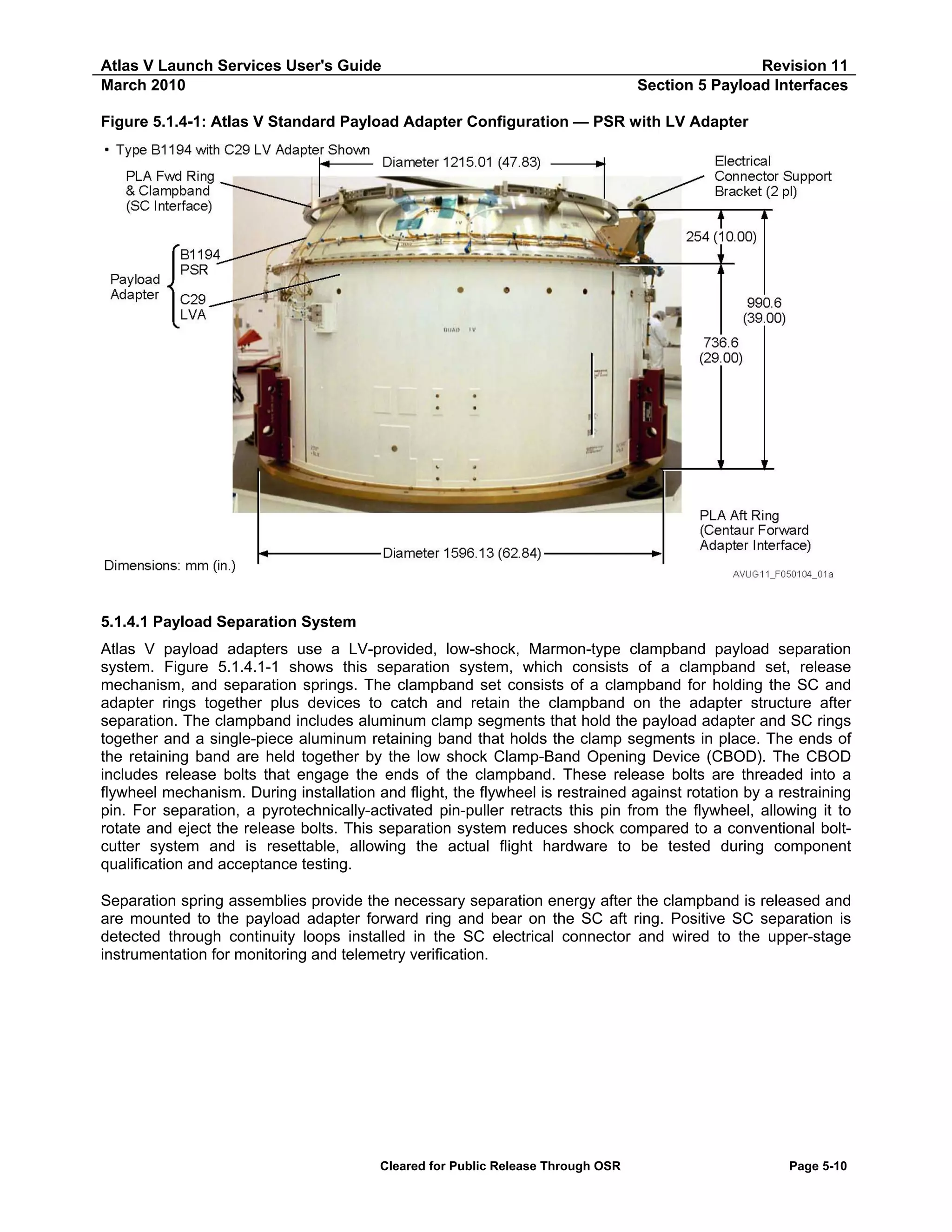
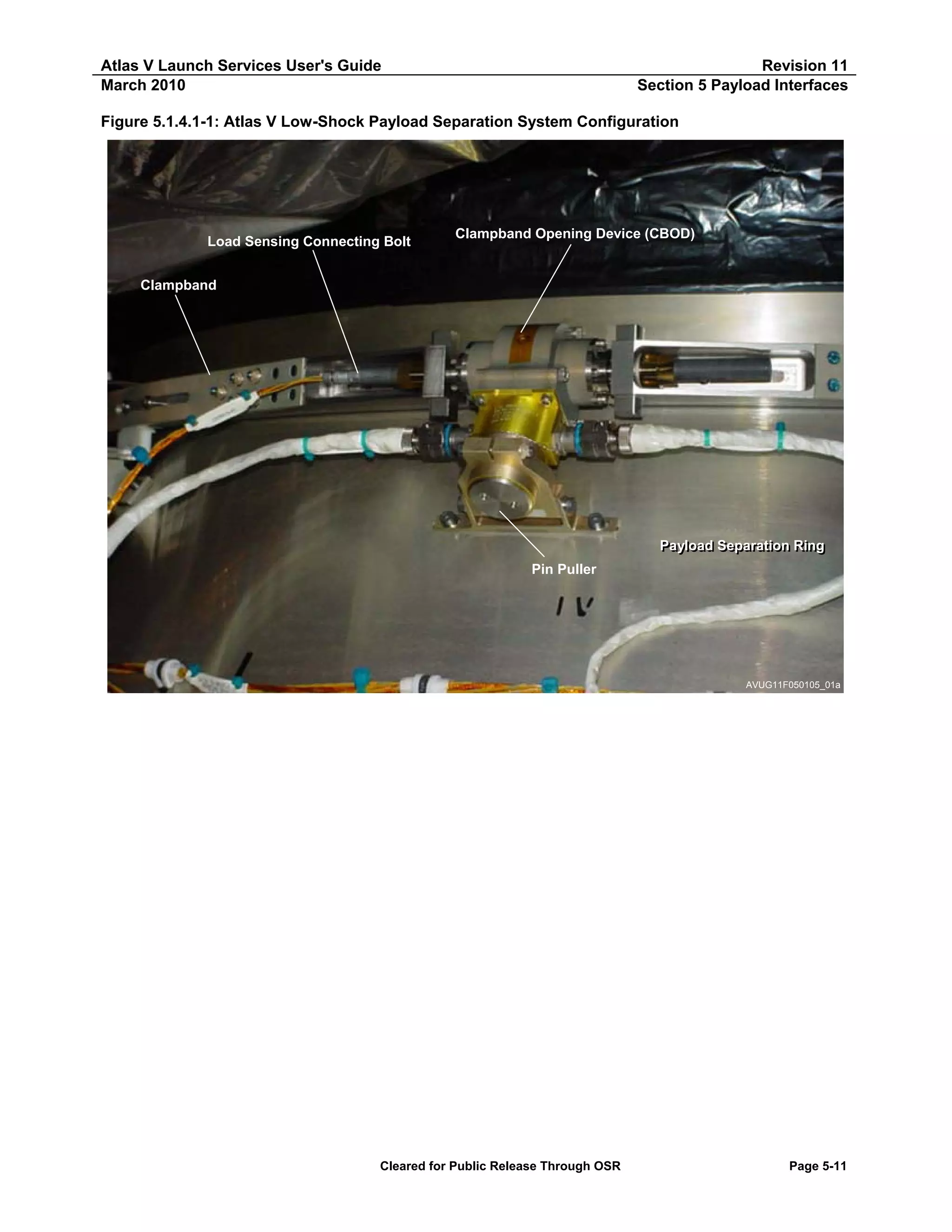
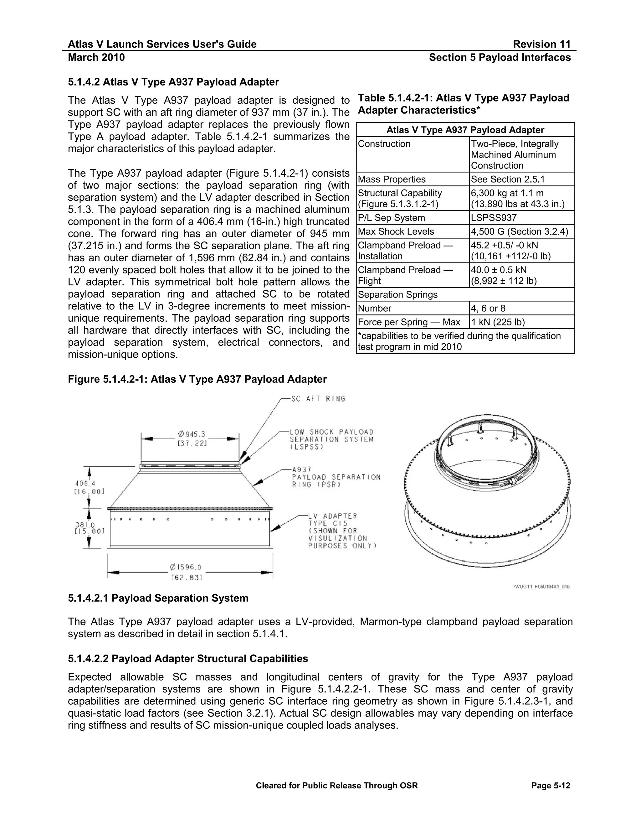
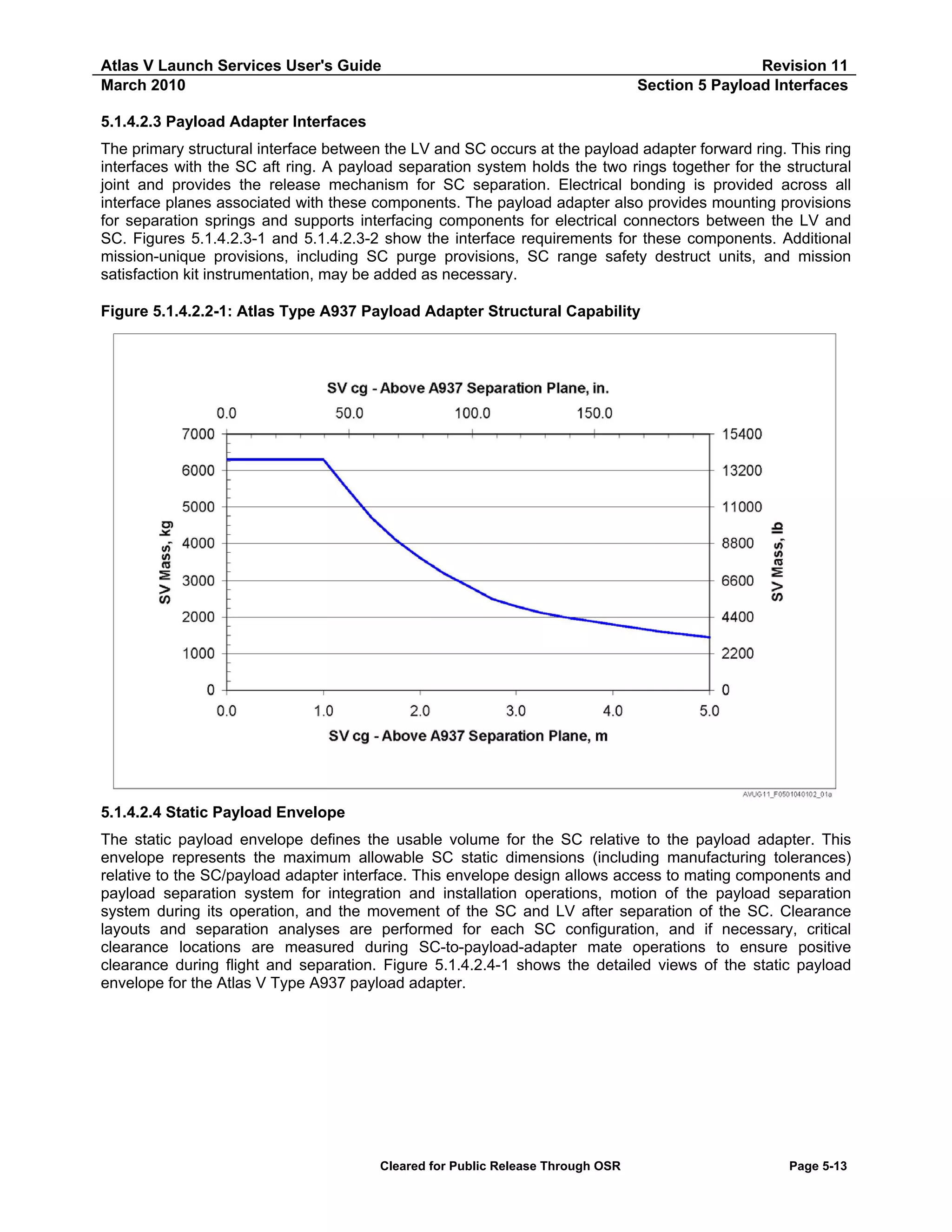
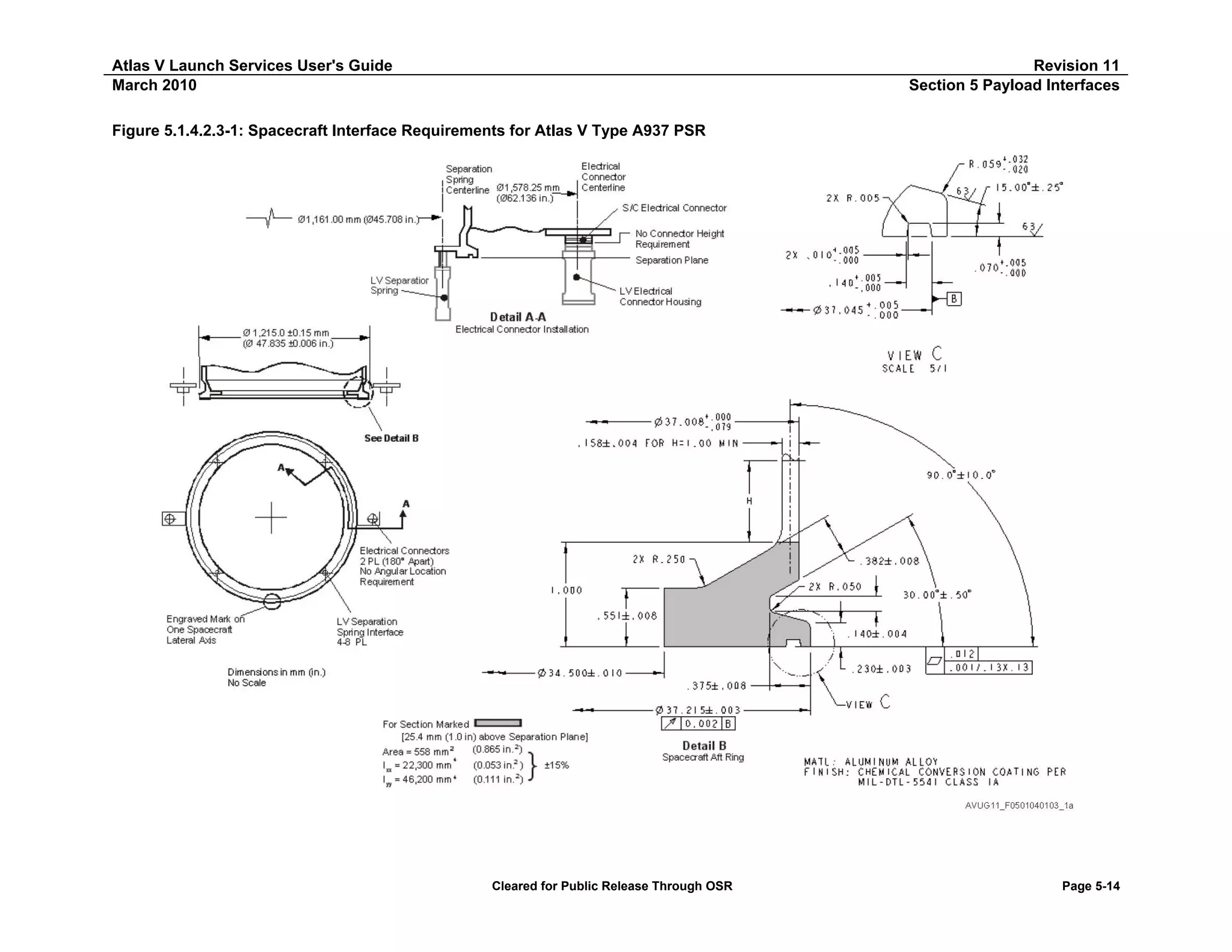
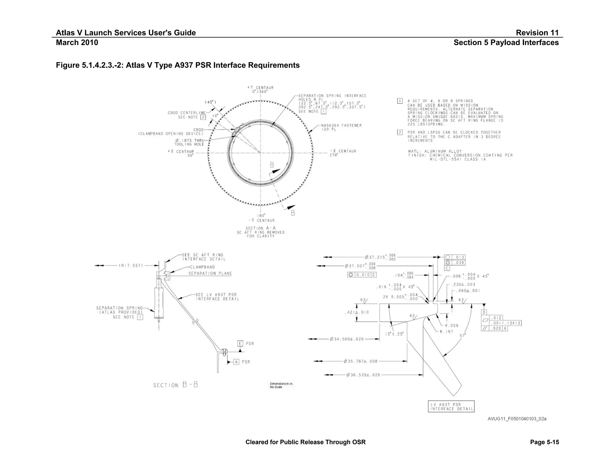
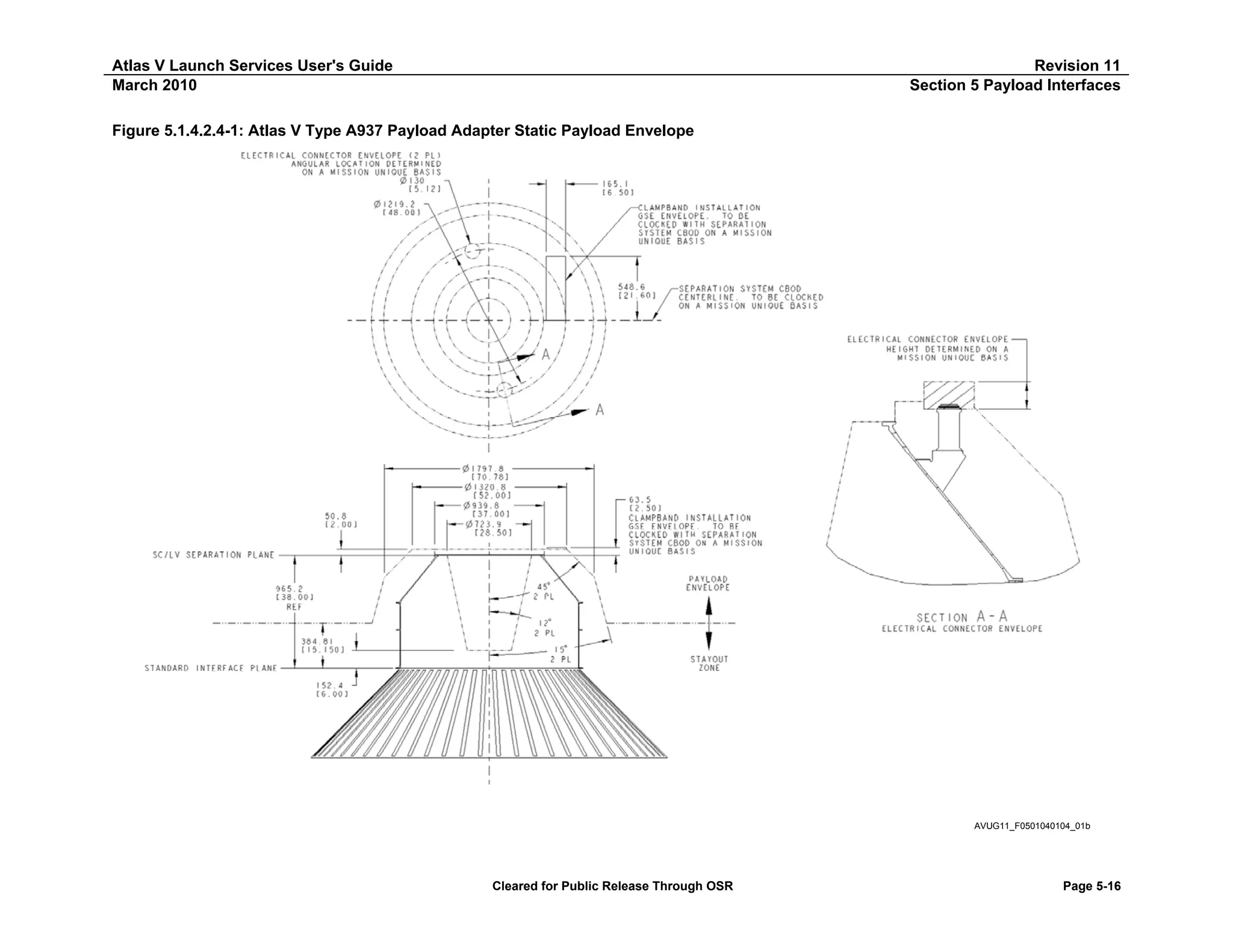
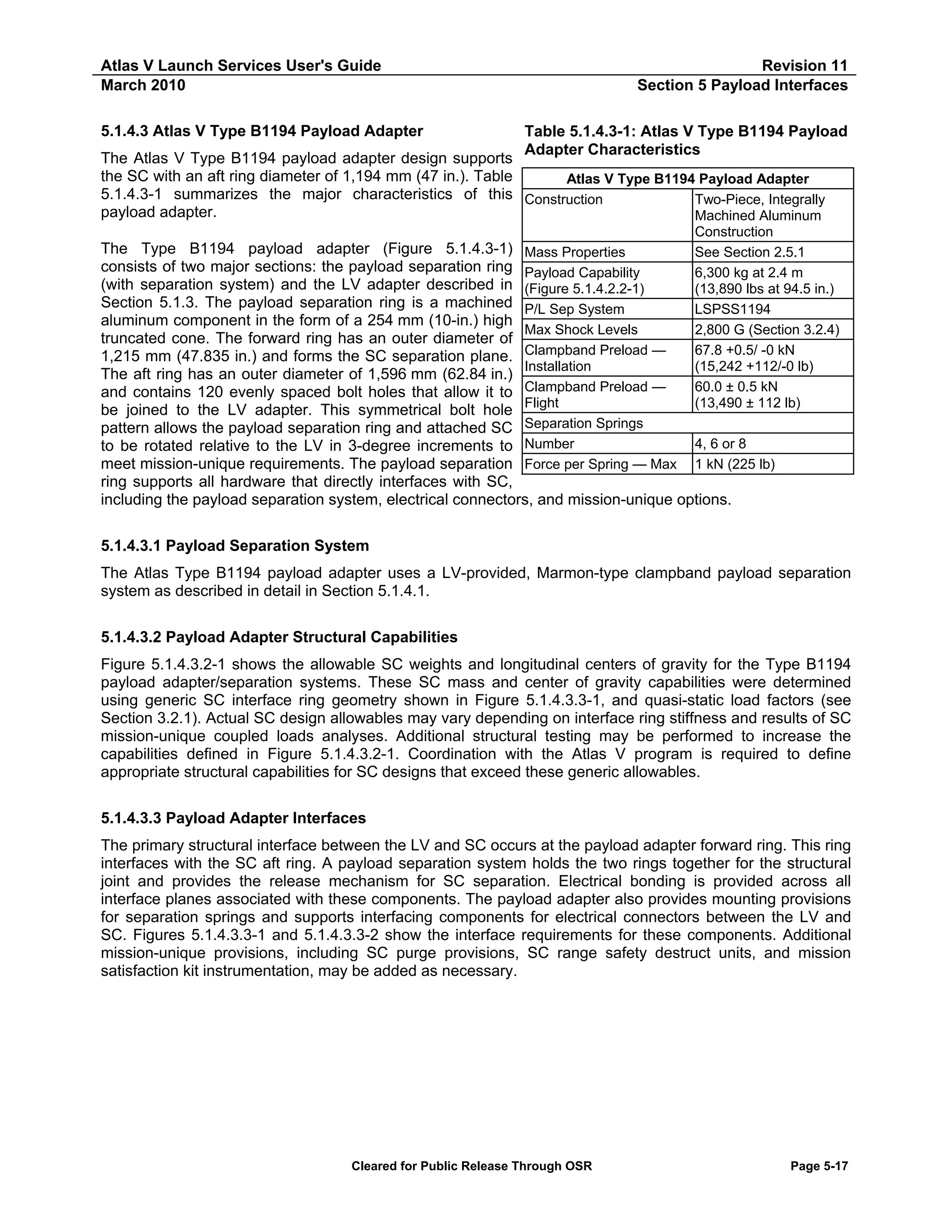
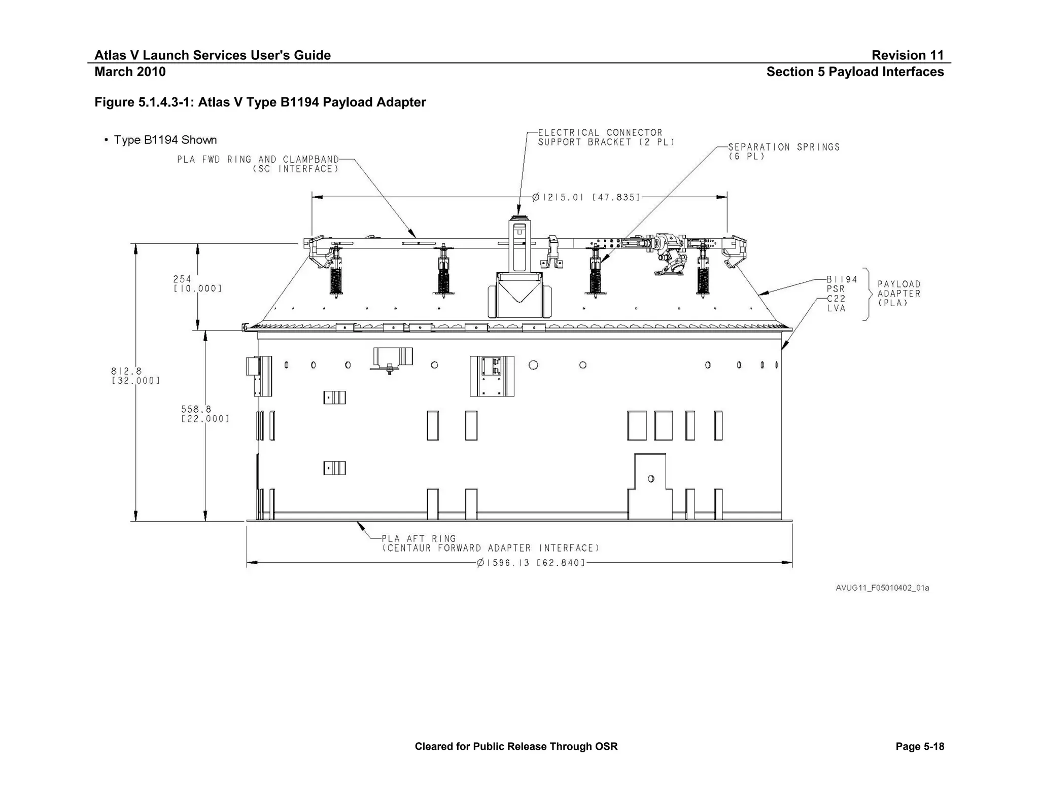
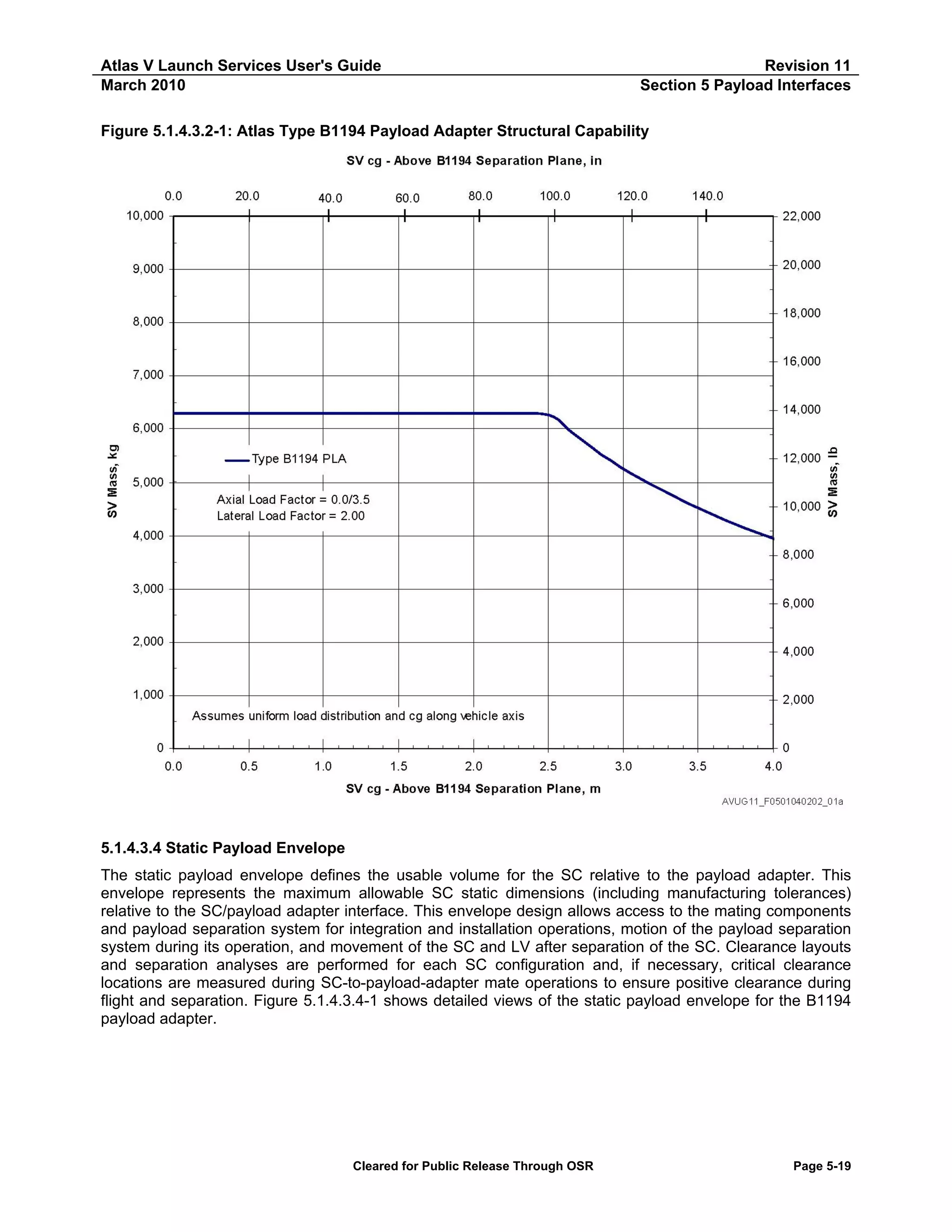
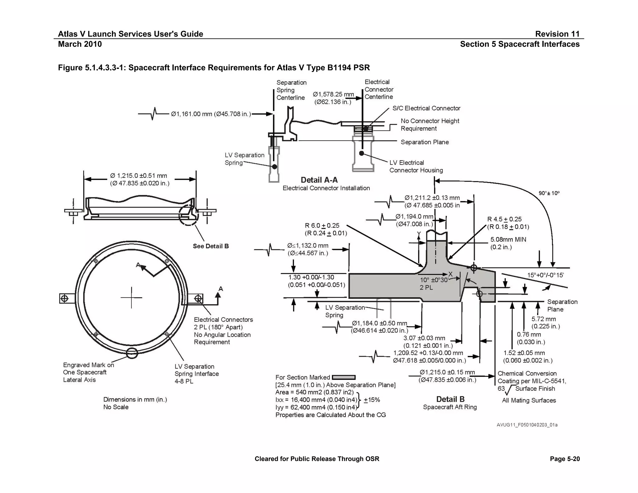
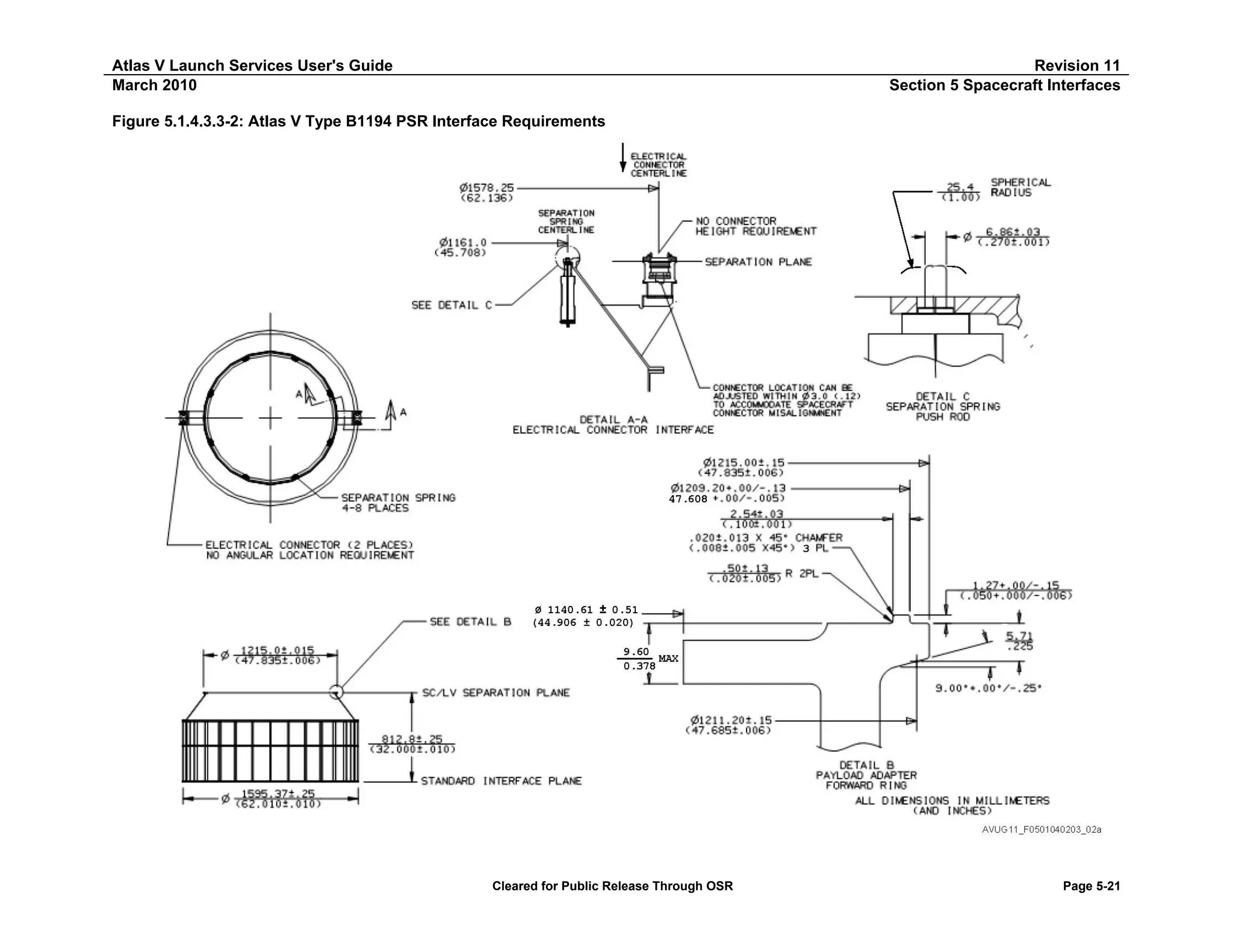
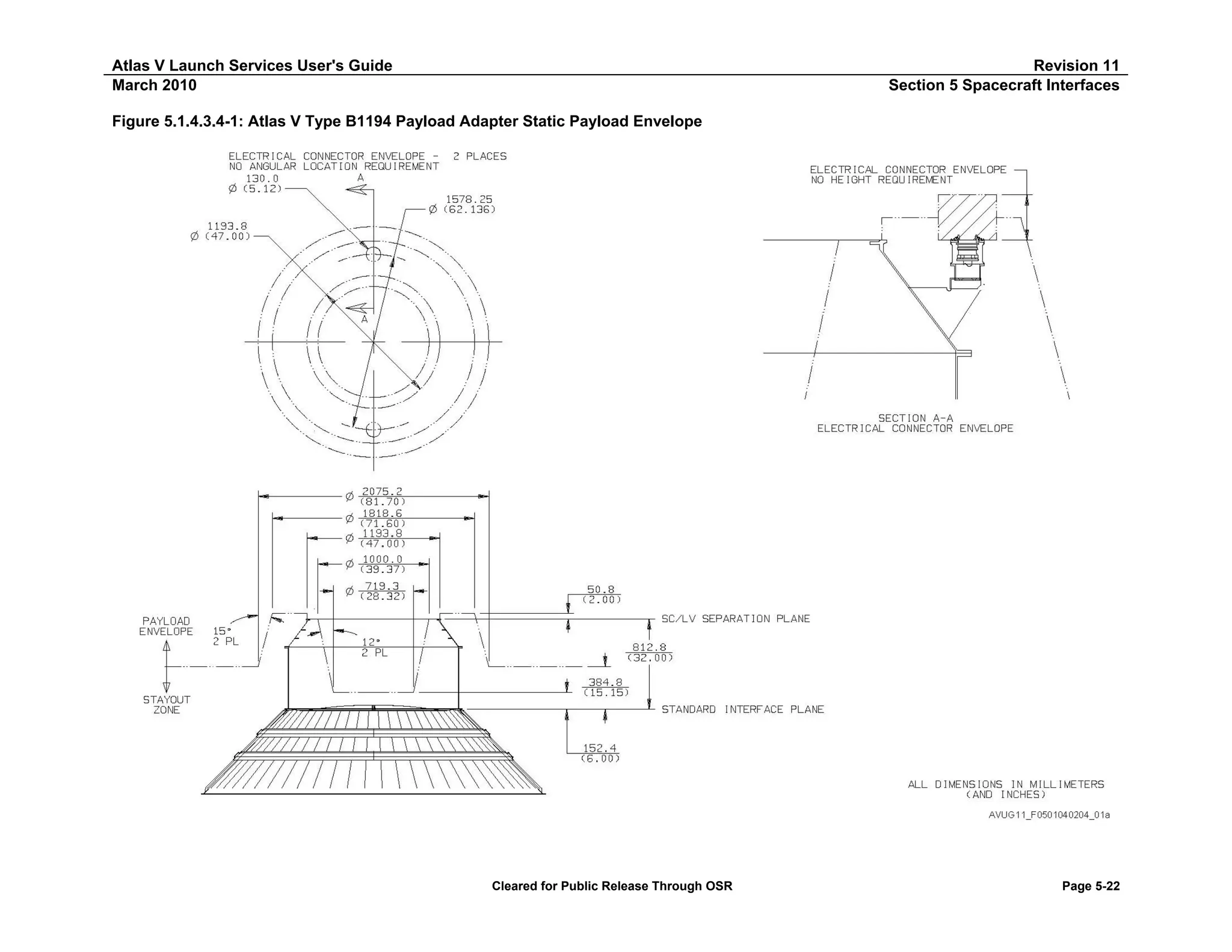
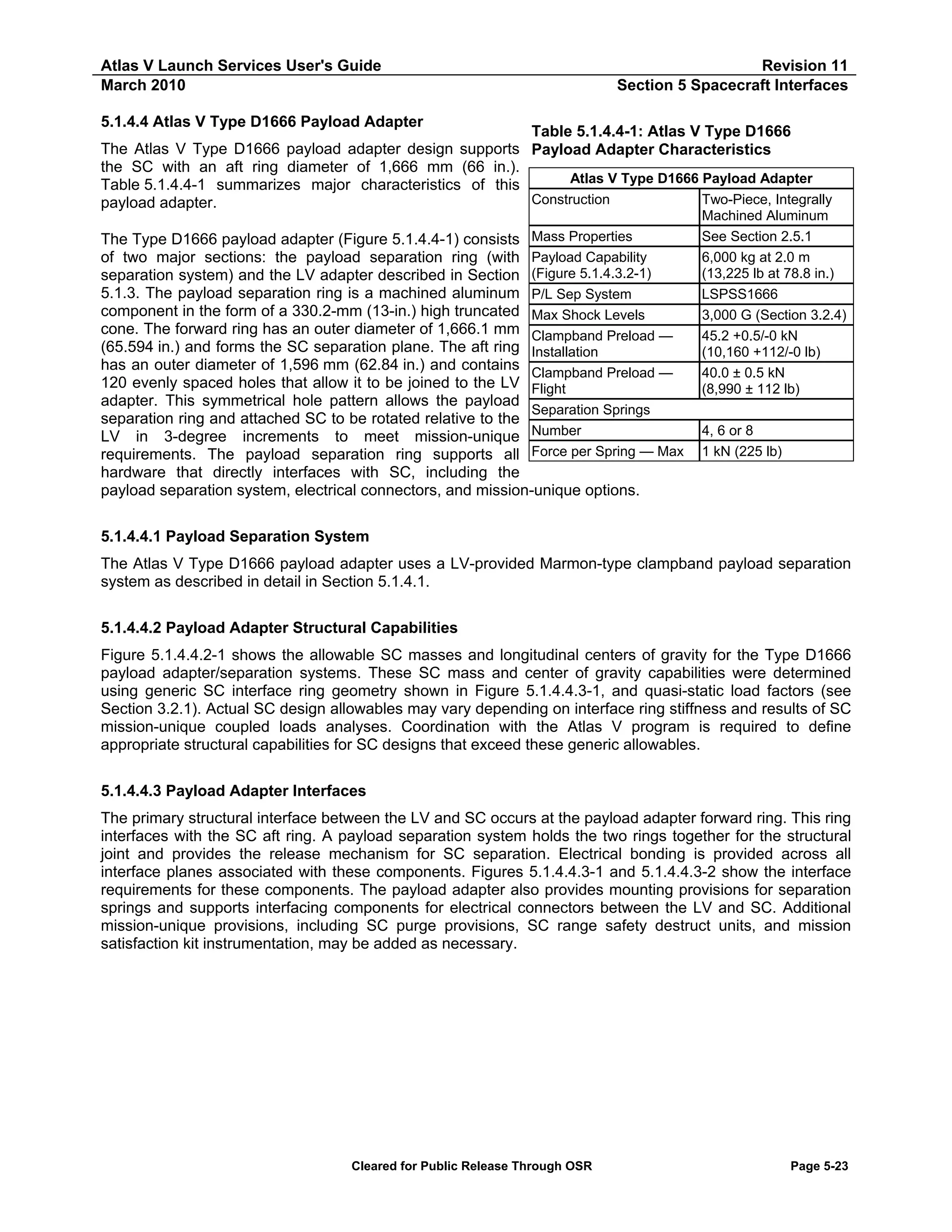
![Atlas V Launch Services User's Guide
March 2010
Revision 11
Section 5 Payload Interfaces
Figure 5.1.4.4-1: Atlas V Type D1666 Payload Adapter
1666.1 [65.594]
330.2 [13]
889 [35]
558.8 [22]
1596.1 [62.84]
AVUG11_F05010403_01d
Cleared for Public Release Through OSR
Page 5-24](https://image.slidesharecdn.com/atlasvusersguide2010-140220084057-phpapp02/75/Atlas-v-usersguide2010-248-2048.jpg)
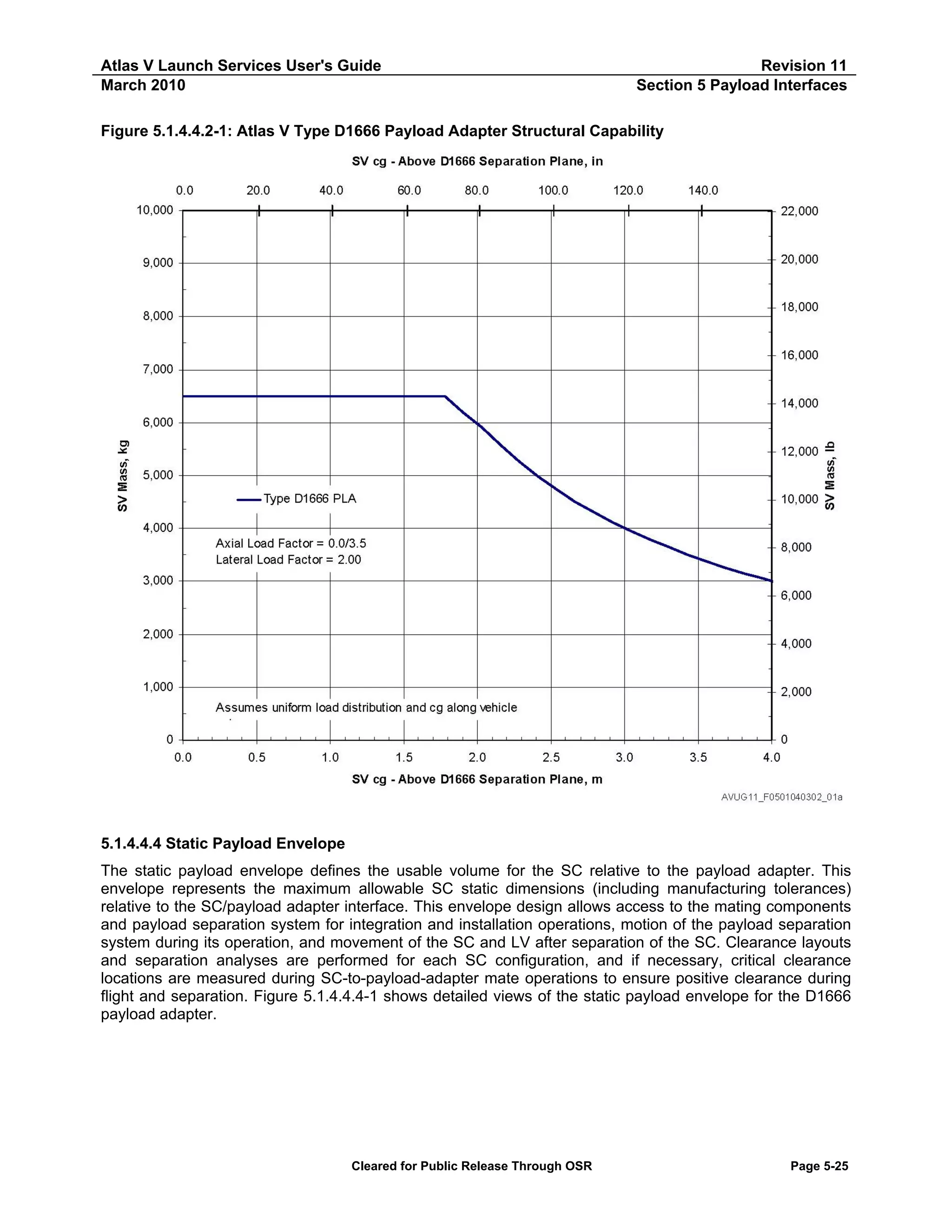
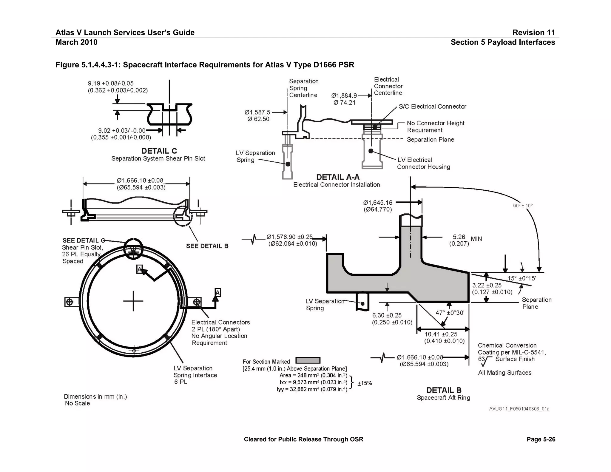
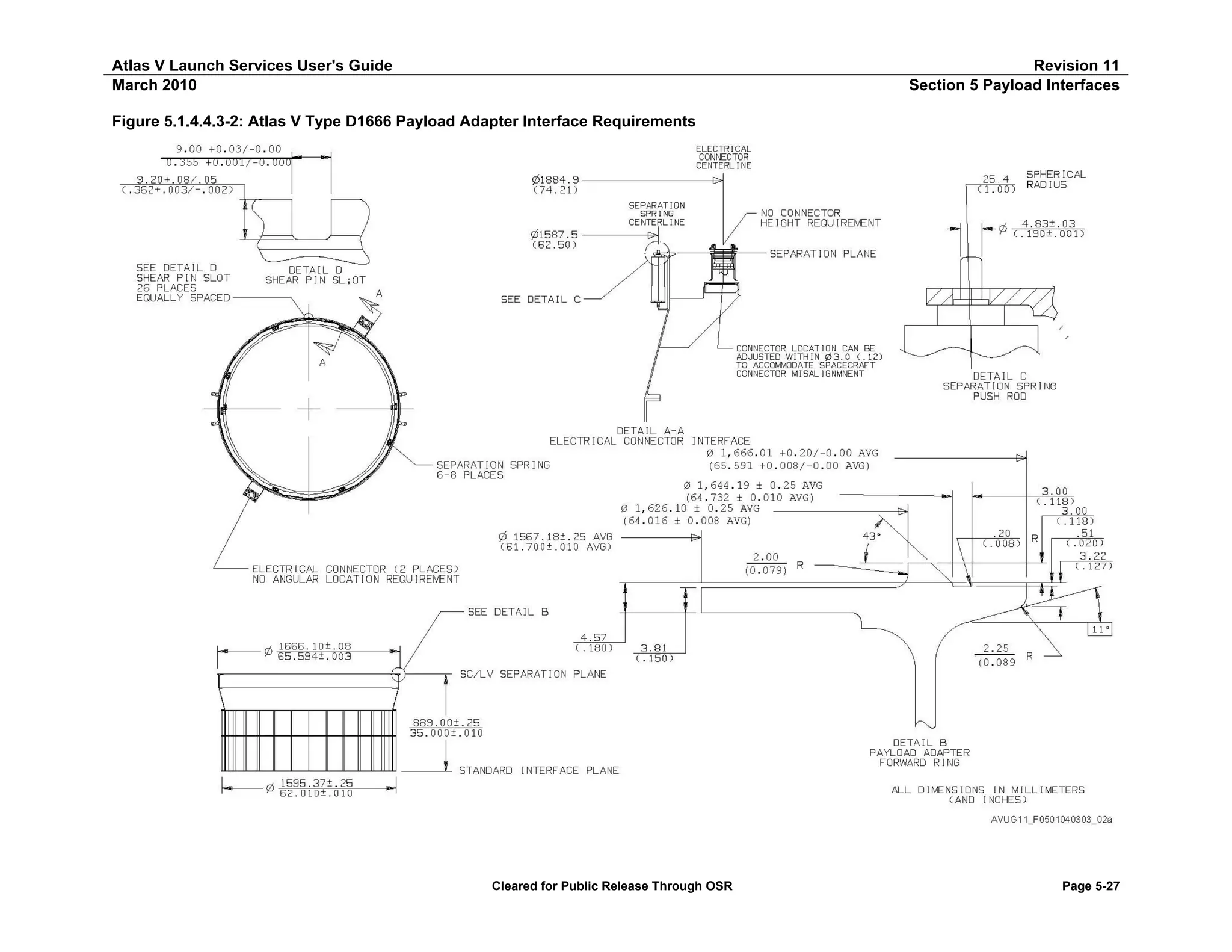
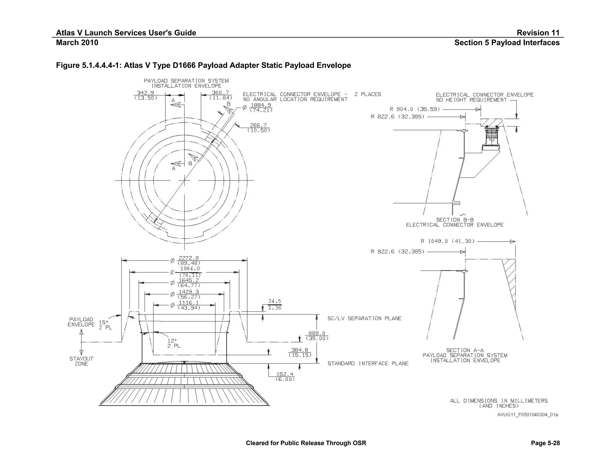
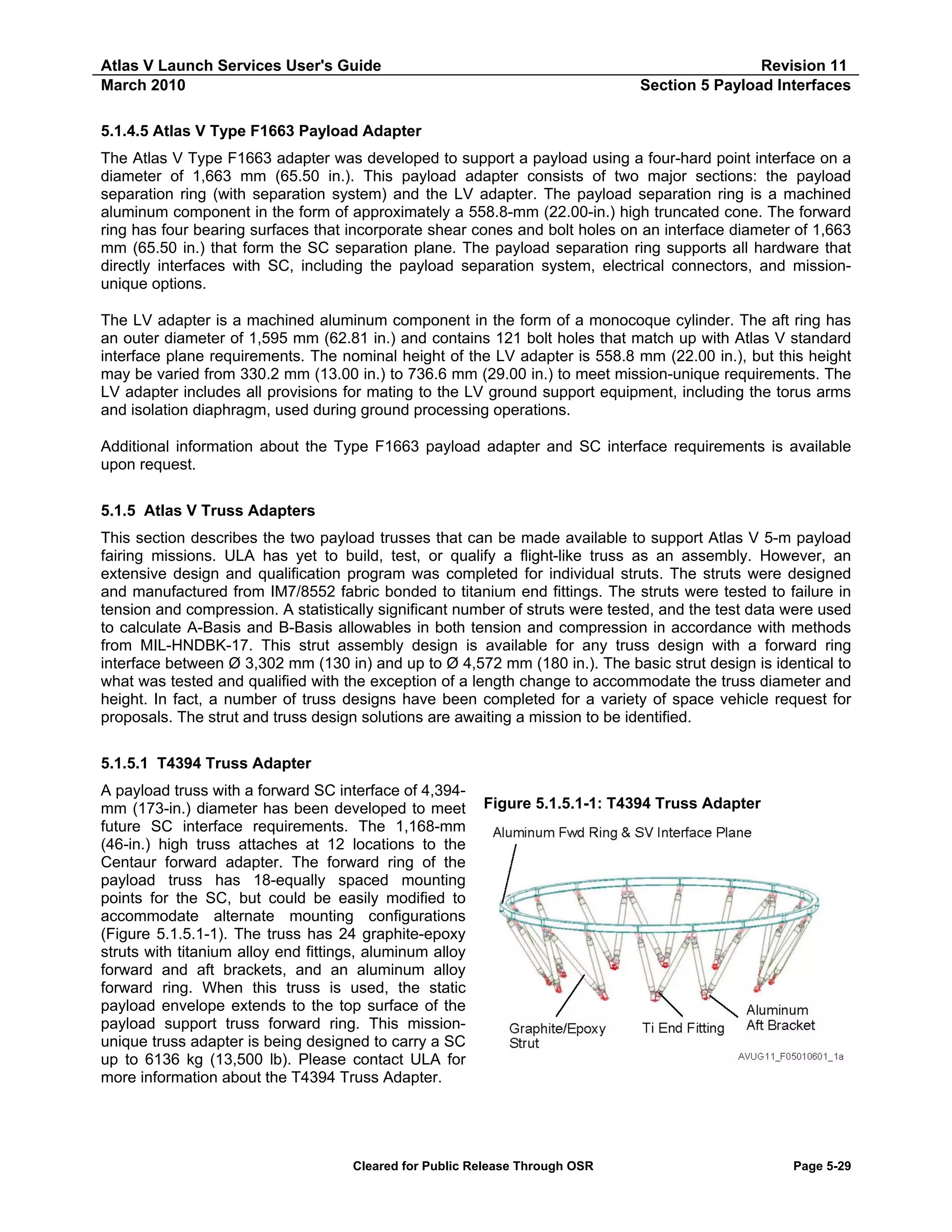
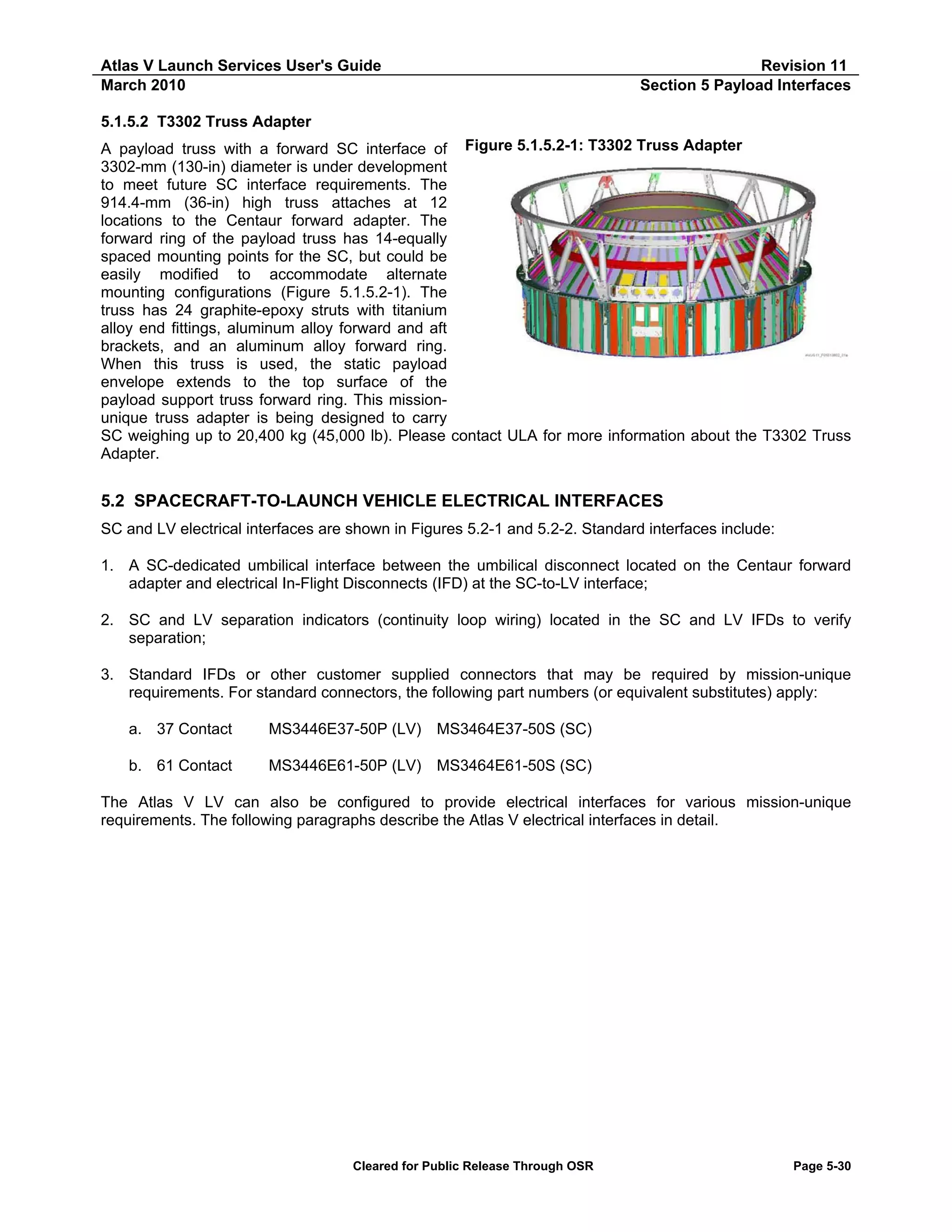
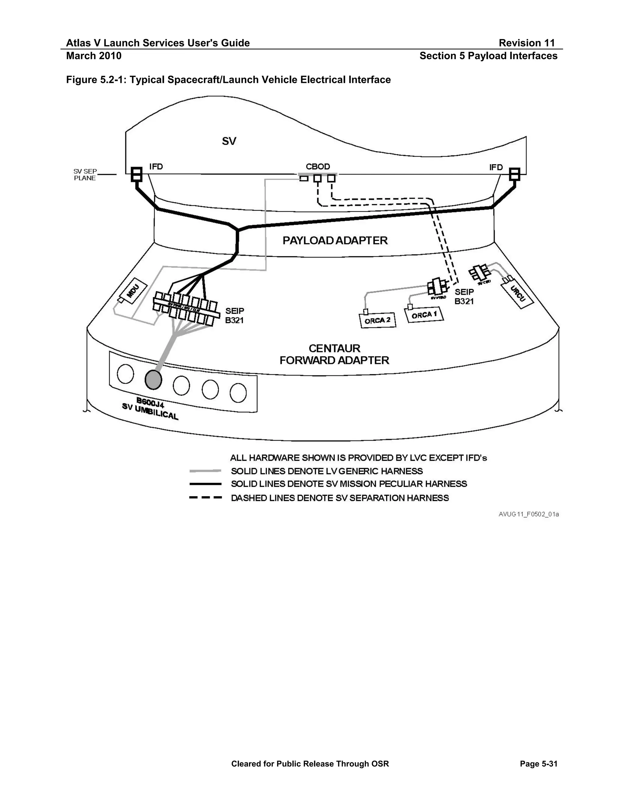
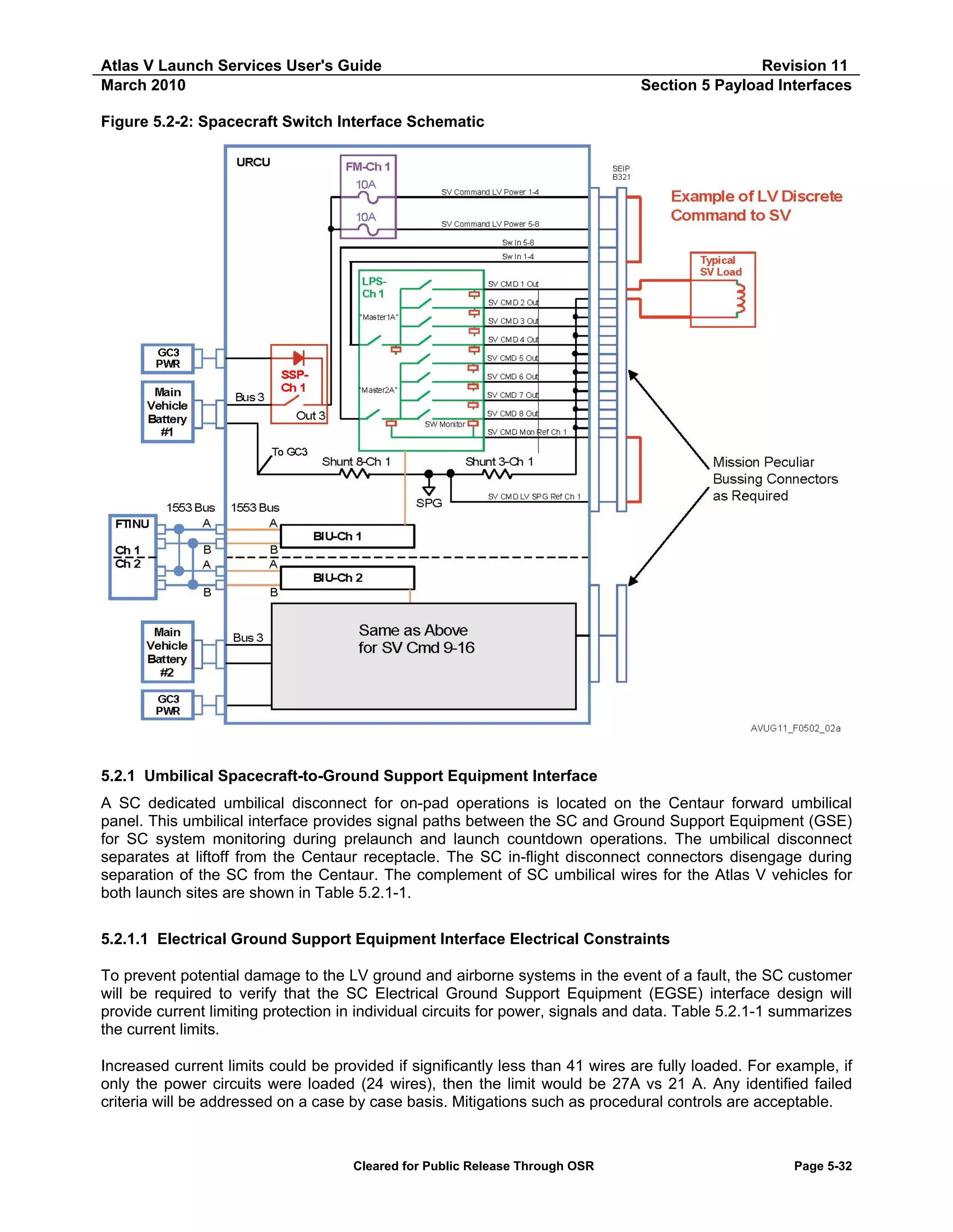
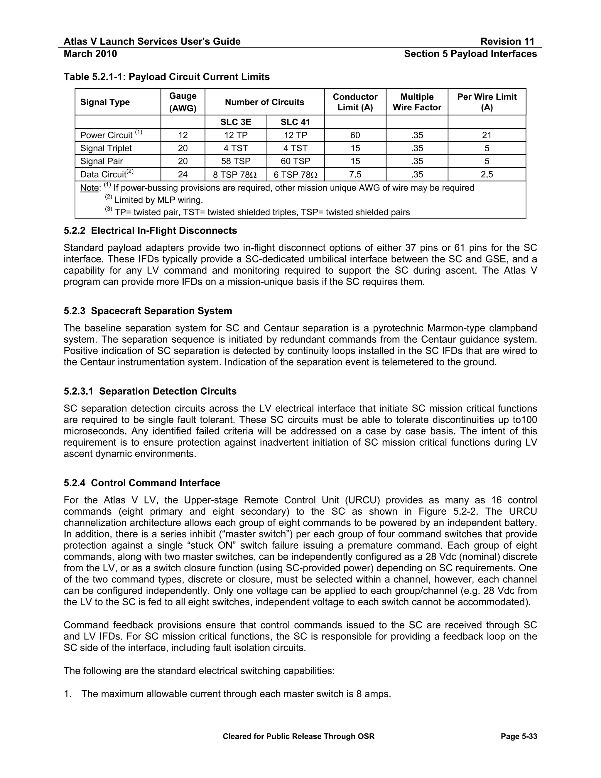
![Atlas V Launch Services User's Guide
March 2010
Revision 11
Section 5 Payload Interfaces
2. Each individual command switch is rated at 4 amps maximum; however, the total current from four
simultaneous ON commands cannot exceed the rating of the corresponding master switch.
3. The allowable voltage range which can be switched is 22-33 Vdc.
4. The system has been optimized for LV-discrete commands at 0.5 amps each or for switch closure
commands at 1.0 amps each. Other mission unique requirements can be accommodated.
5. Commands can be controlled in 20 msec timing increments, individually or simultaneously per mission
requirements. Mission unique implementations will accommodate Atlas V redundancy management
requirements to ensure command sequences exceed 80 msec in duration. Such sequences will
accommodate the maximum command dropout duration in the unlikely event of an FTINU switch-over.
Mission-unique compatibility analyses are performed for any interfaces that use these commands to verify
proper circuit interaction and appropriate circuit electrical deratings.
5.2.5 Spacecraft Environment Instrumentation
The Atlas V program offers a suite of instrumentation options to capture SC environments.
5.2.5.1 Spacecraft Telemetry Interface
The LV provides a mission satisfaction telemetry kit as an option to ascertain certain vehicle environments
and ensure ICD requirements are met. Low frequency data (less than 200 Hz) can be captured through the
LV Data Acquisition System (DAS) located on the Centaur. The Digital Telepak and Telemetry and Data
Relay Satellite System (TDRSS) transmitter combination can provide up to 32 channels of wideband data
(up to 8-kHz data) with a Pulse-Code Modulation (PCM) (Quadrature Phase-Shift Keying [QPSK]) telemetry
format. Additional instrumentation may be added optionally up to the bandwidth and interface capabilities of
these data systems. Data recorded from these measurements are provided post launch to evaluate
compliance with ICD environmental requirements.
The available mission satisfaction instrumentation consists of (1) two acoustic measurements located inside
the PLF, (2) three acceleration measurements at the SC-to-LV separation plane spaced 120 degrees apart,
(3) three orthogonal vibration measurements at the SC-to-LV separation plane, (4) three orthogonal shock
measurements at the SC-to-LV separation plane, (5) one absolute pressure measurement located in the SC
compartment, and (6) one temperature measurement located in the SC compartment.
5.2.5.2 Spacecraft Telemetry Options
The Atlas V program offers two options for transmission of SC data.
5.2.5.2.1
Radio Frequency Reradiation GSE Interface
A modification of the Atlas V PLF is made to accommodate an RF reradiating antenna system to reradiate
SC radio frequency (RF) telemetry and command signals from inside the PLF to a GSE site before launch. It
must be noted that radiating RF inside an enclosed fairing will produce an enhanced resonant environment
that may be in excess of SC or LV limits. Early in the integration process, ULA will perform an EMC analysis
to evaluate this condition.
5.2.5.2.2
Spacecraft Serial Data Interface
The Atlas V LV can provide transmission of two SC serial data interfaces. SC data are interleaved with LV
DAS data and serially transmitted in the PCM bit stream. For each data interface, the SC provides
Nonreturn-to-Zero Level (NRZ-L) coded data and a clock from dedicated drivers (as an input to the LV). SC
data and clock signals must be compliant with Electronics Industry Association RS-422, Electrical
Characteristics of Balanced Voltage Digital Interface Circuits, with a maximum data bit rate of 2 kbps. SC
Cleared for Public Release Through OSR
Page 5-34](https://image.slidesharecdn.com/atlasvusersguide2010-140220084057-phpapp02/75/Atlas-v-usersguide2010-258-2048.jpg)
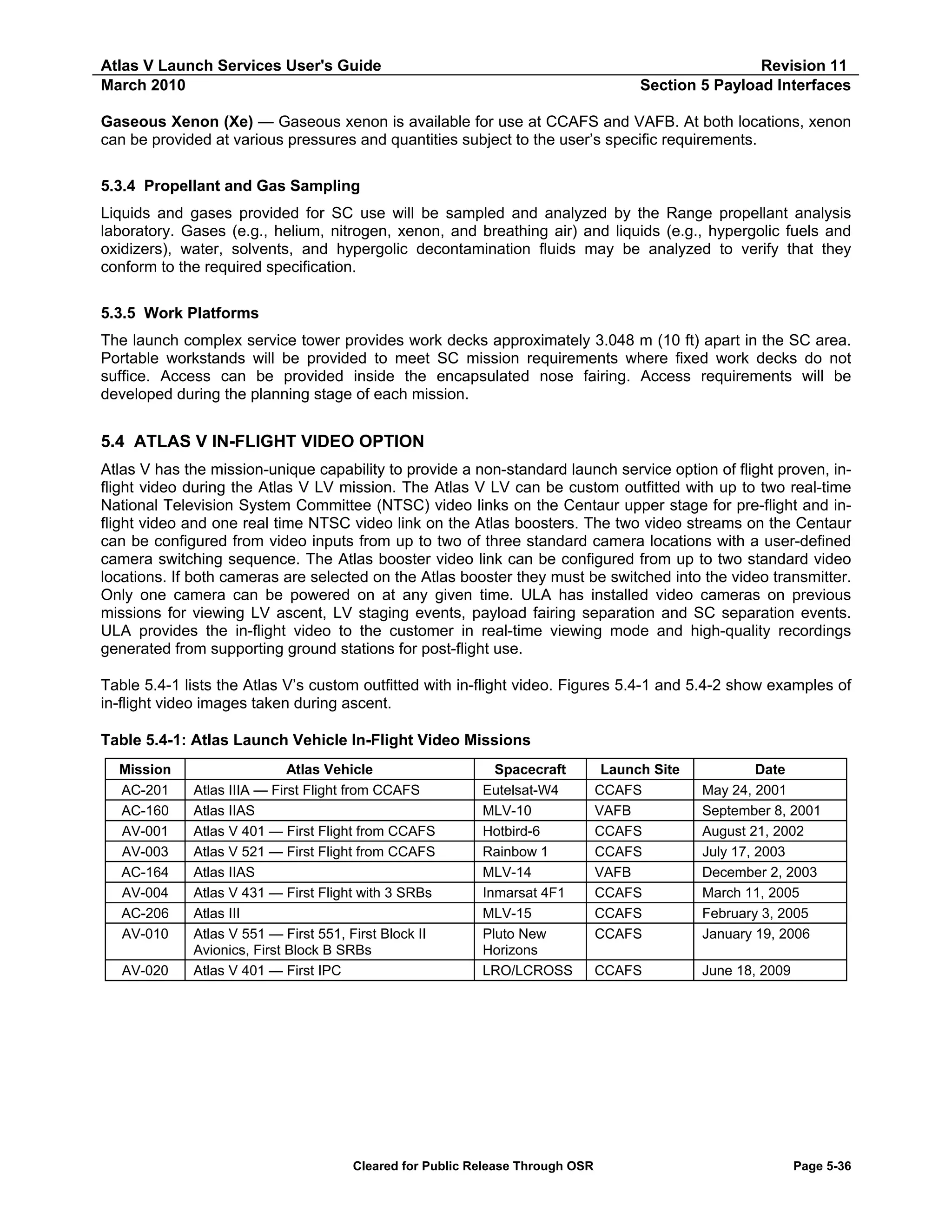
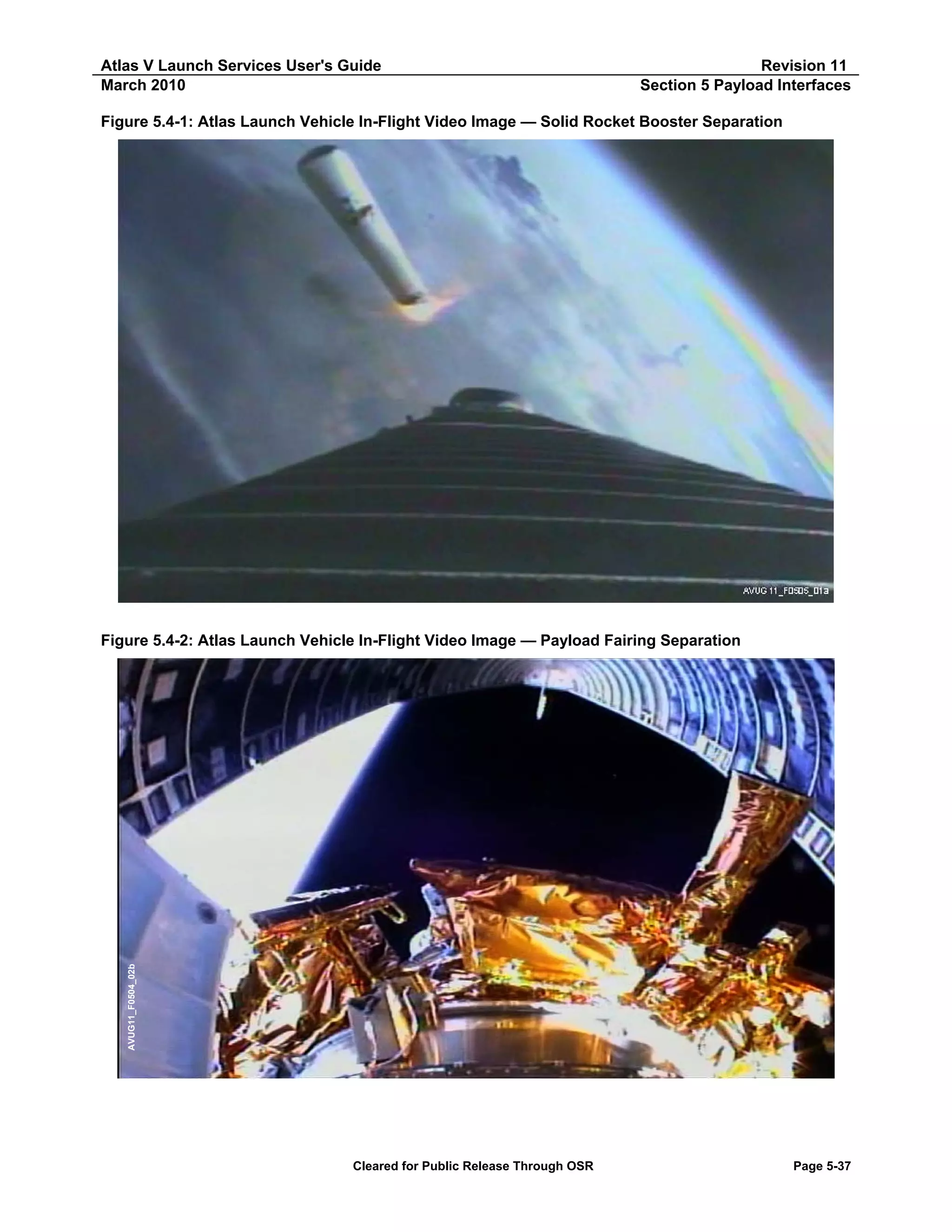
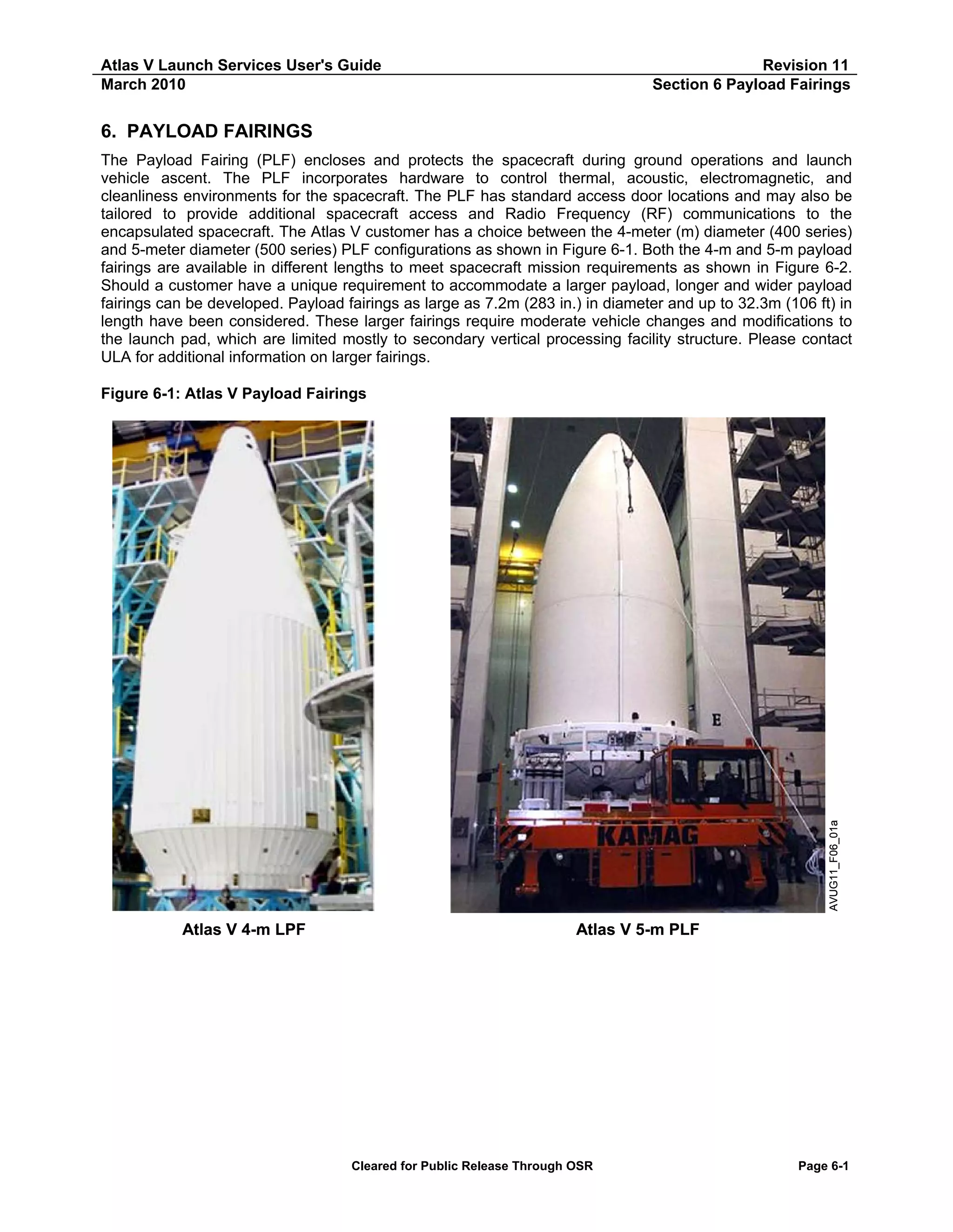
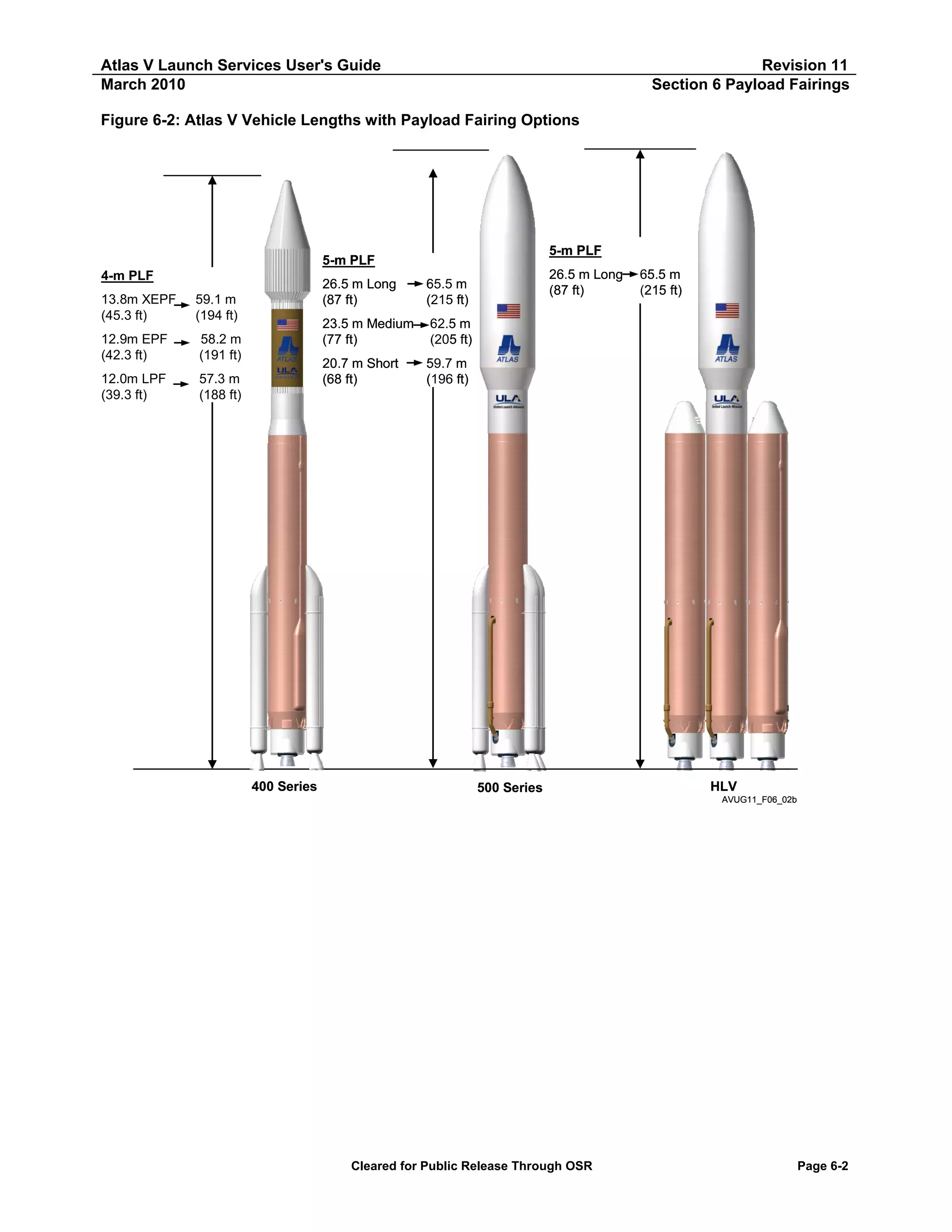
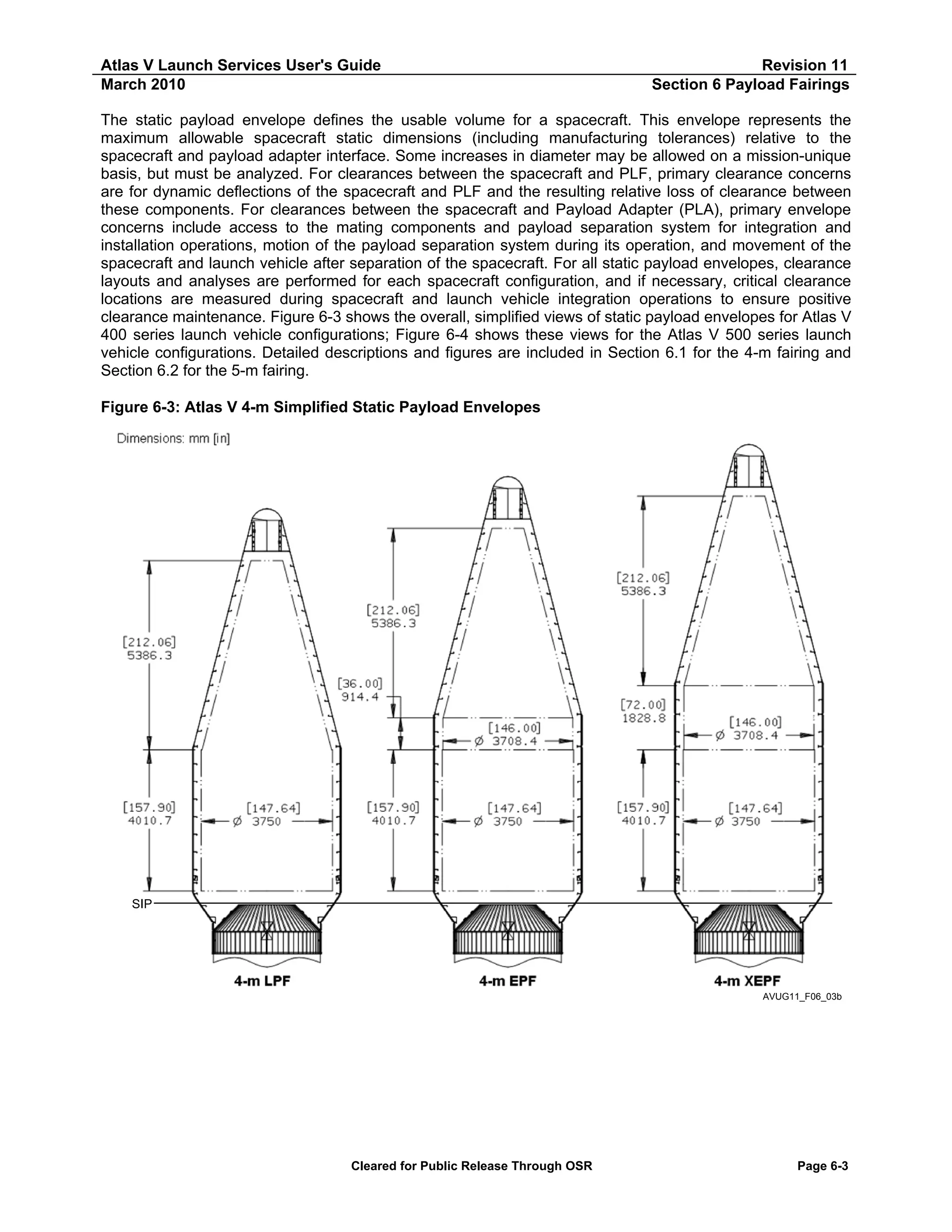
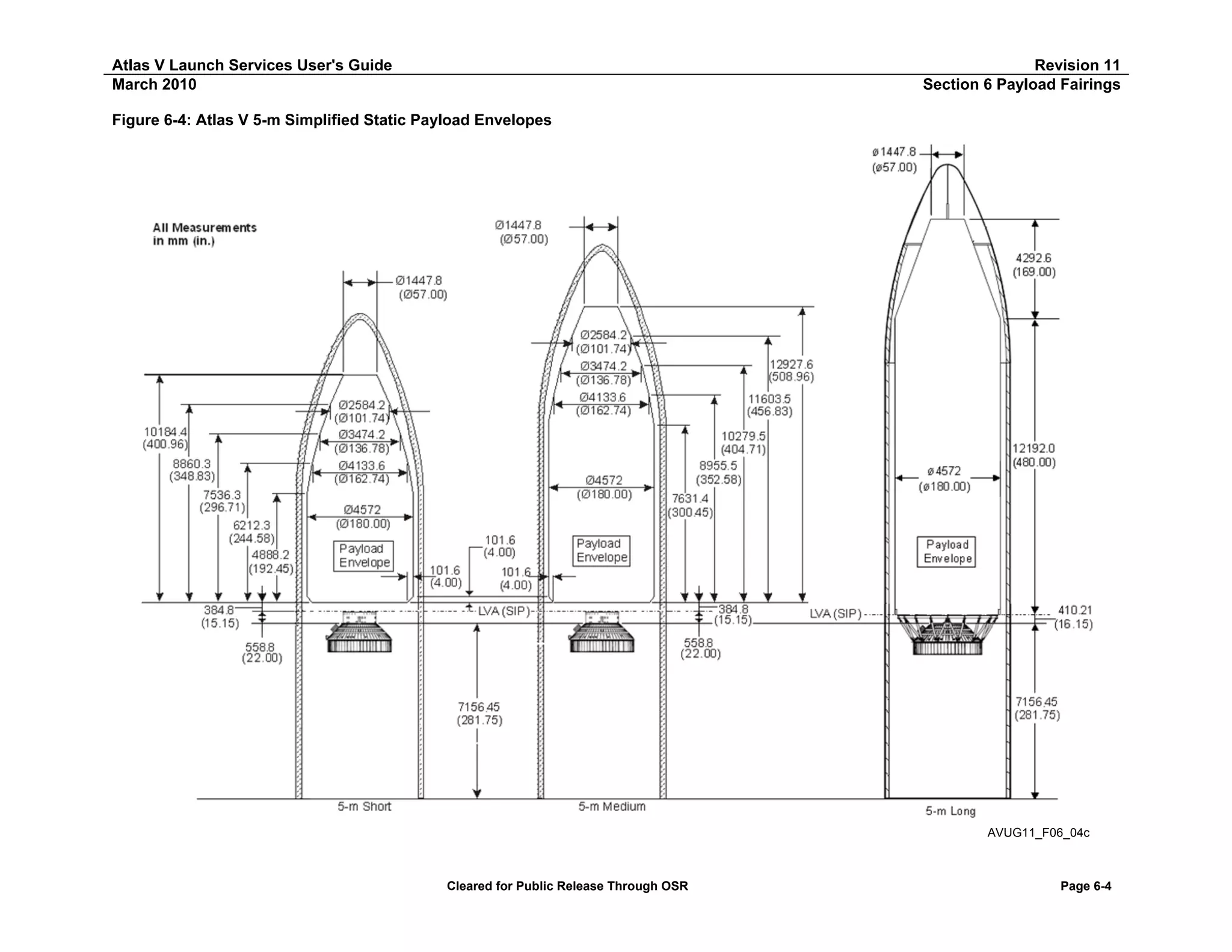
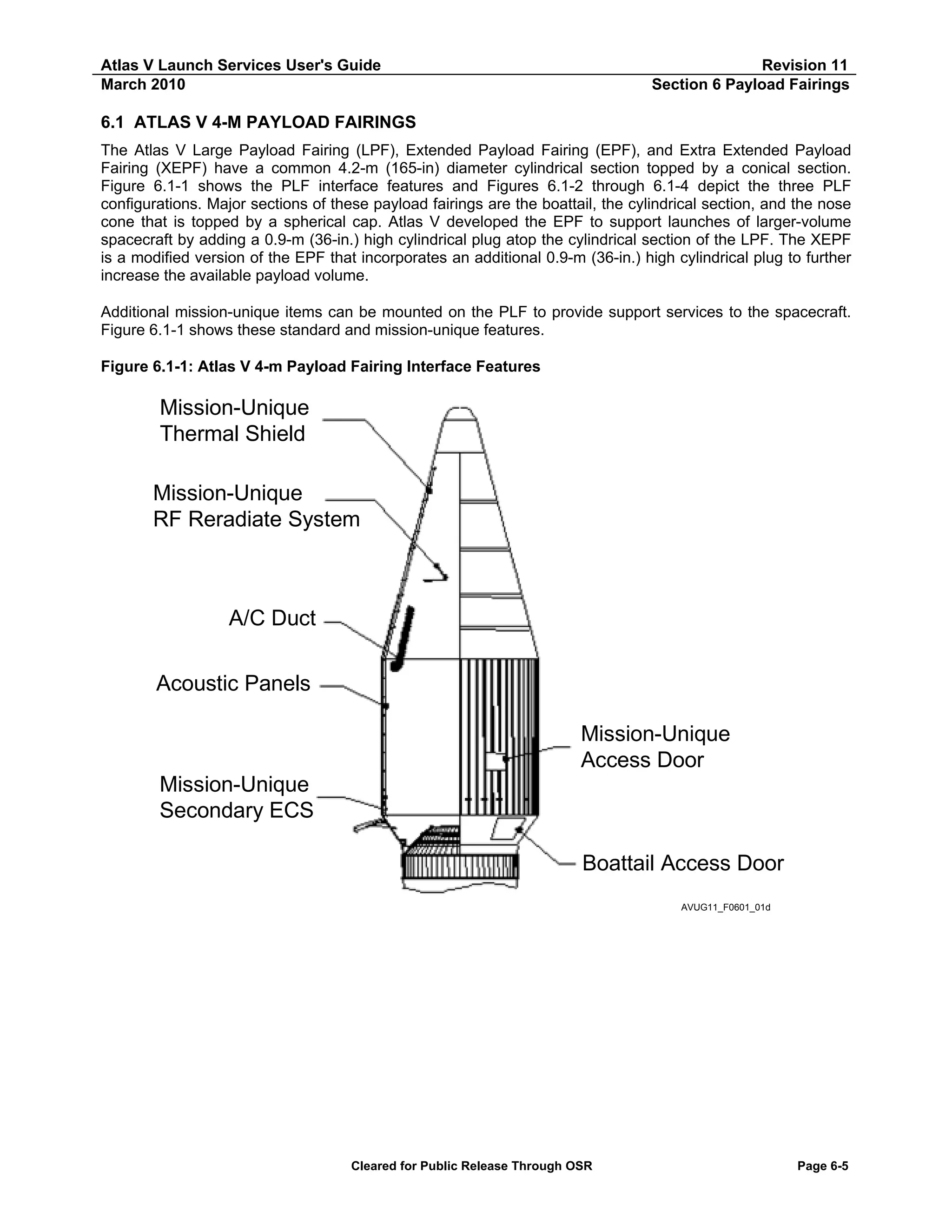
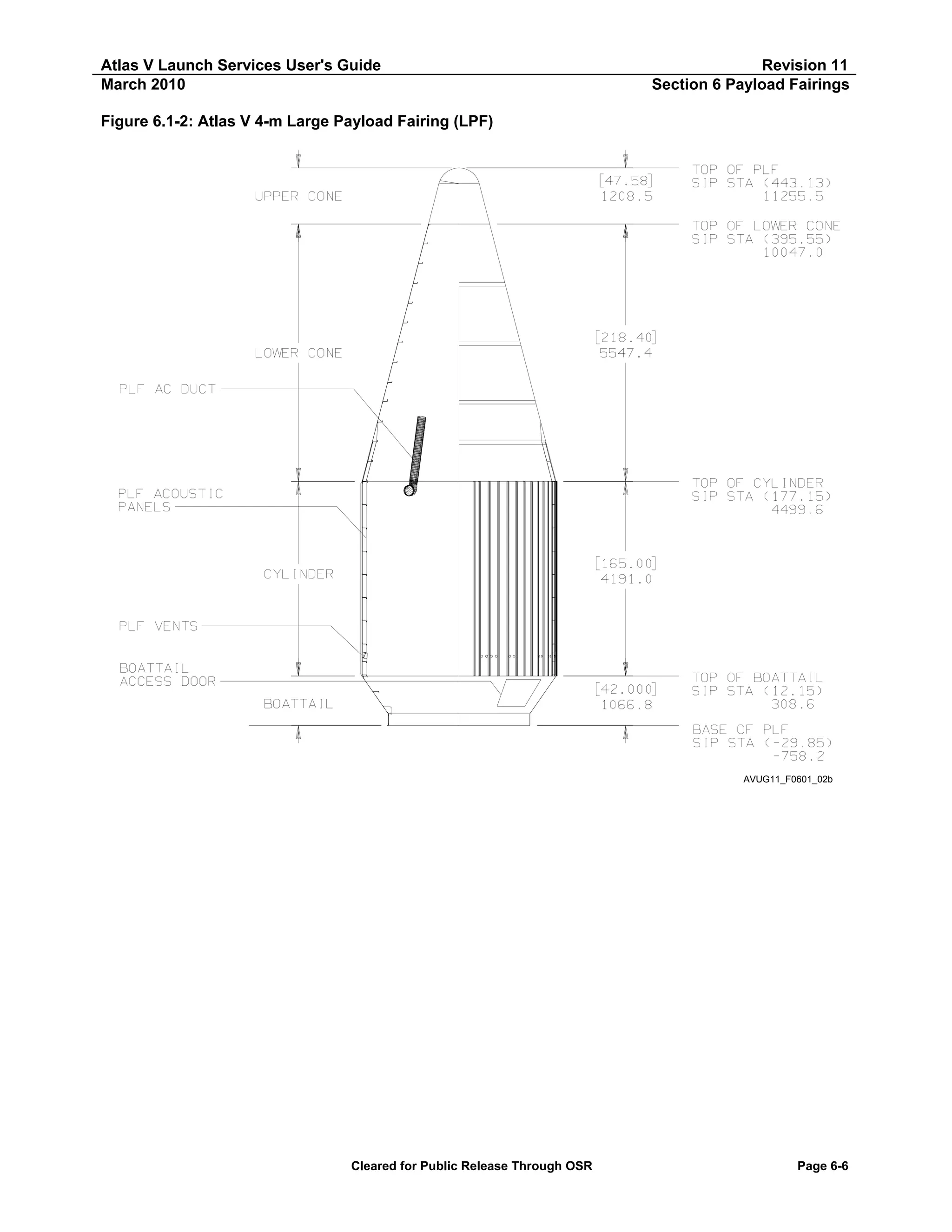
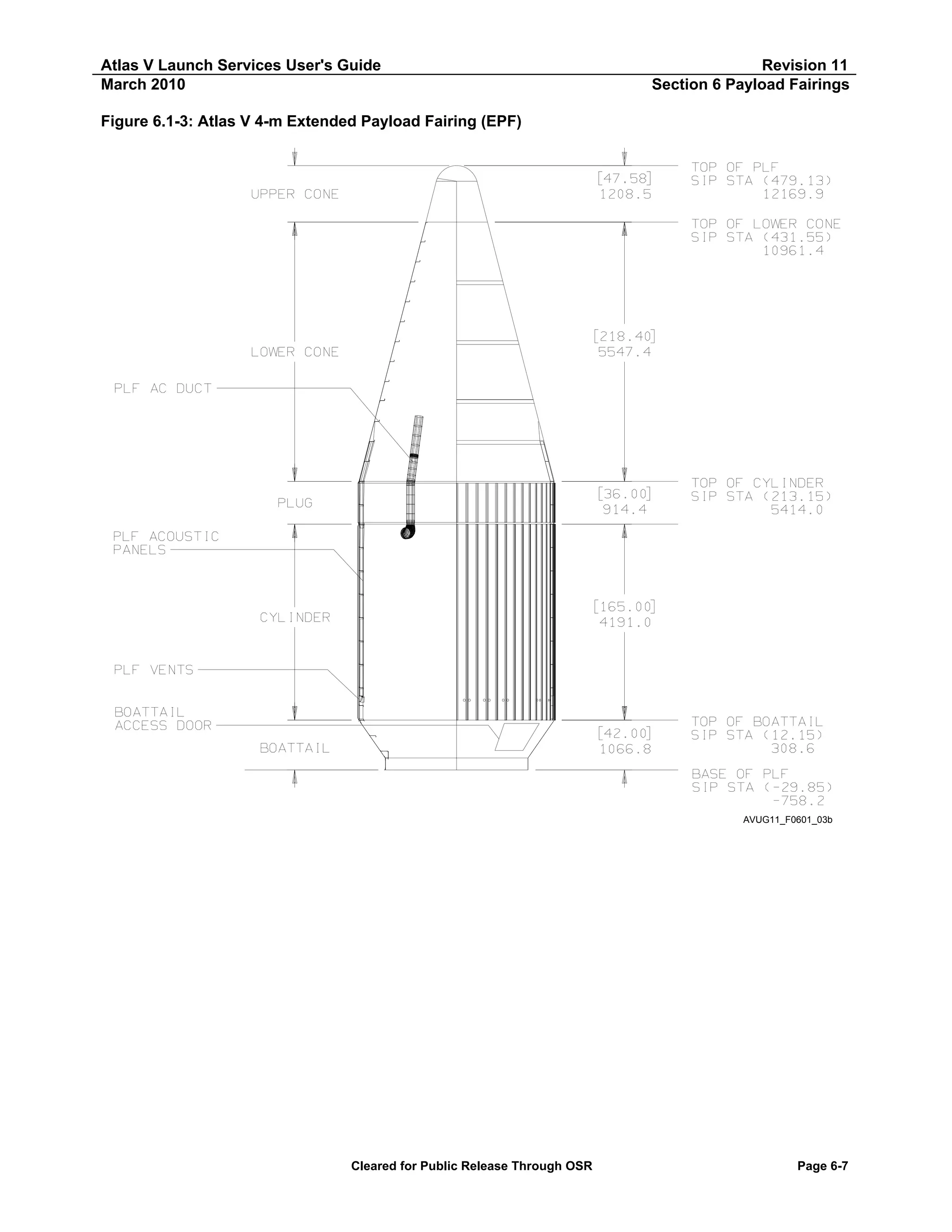
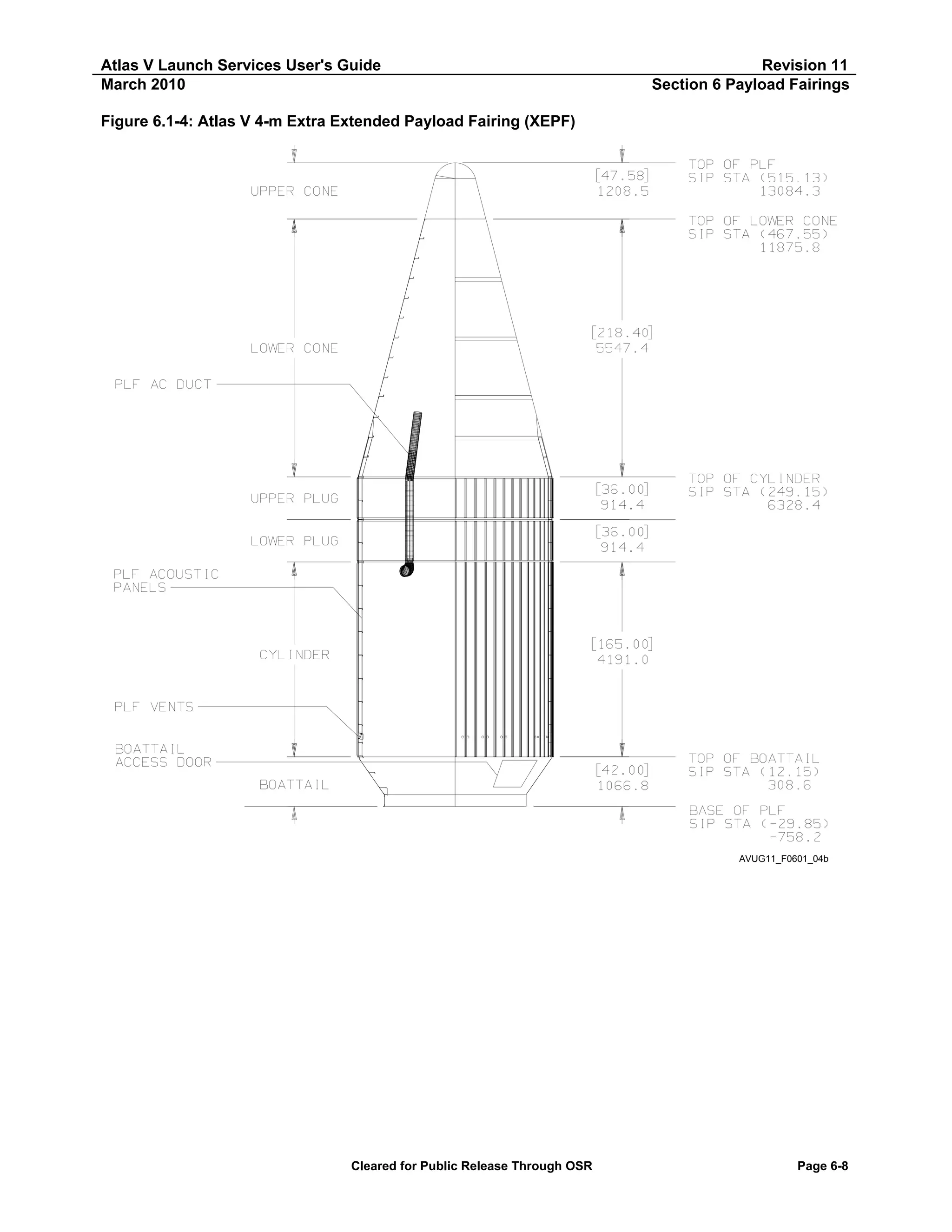
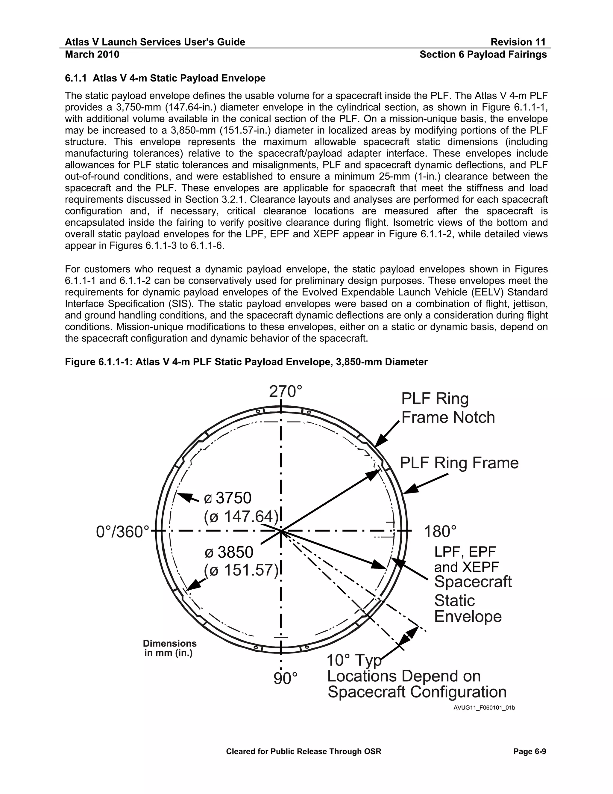
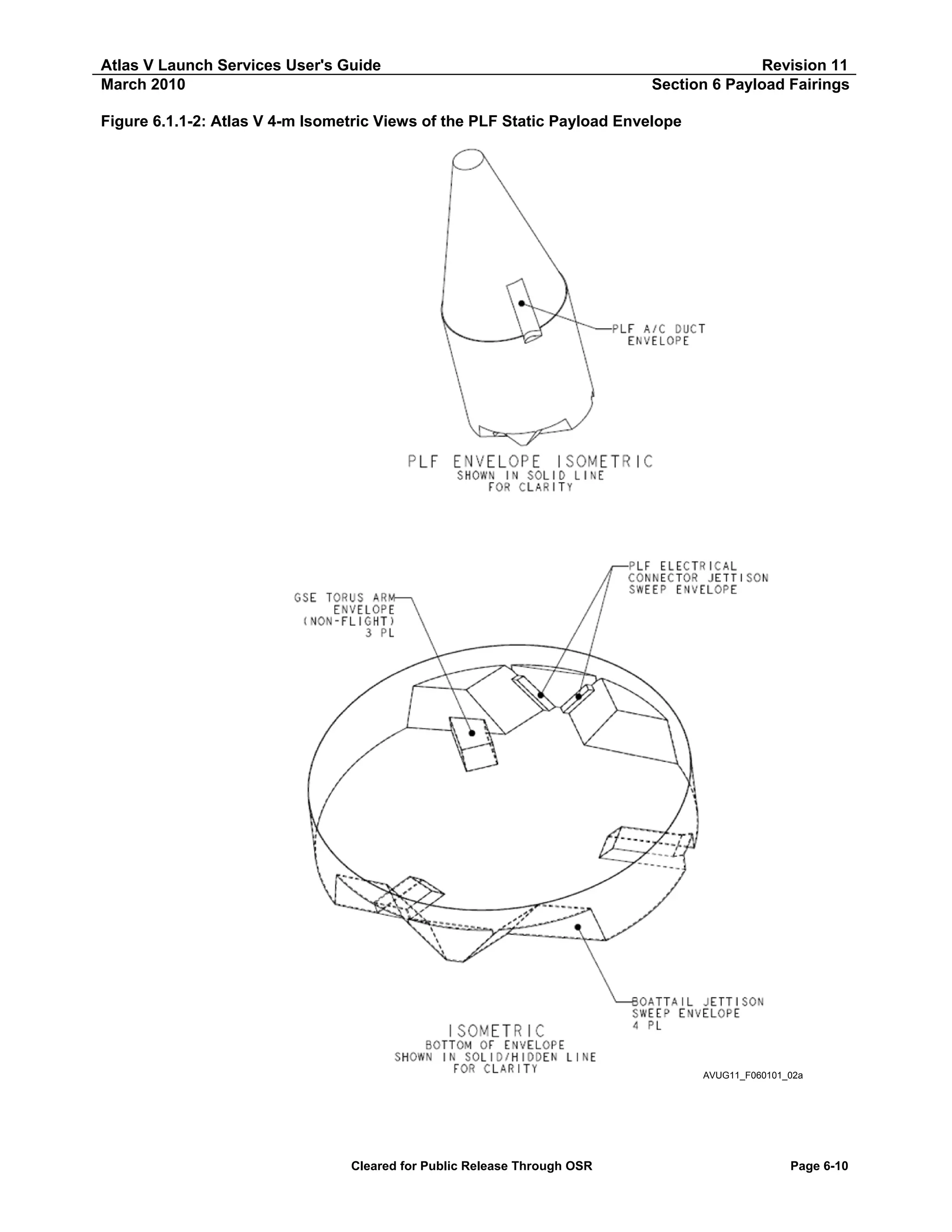
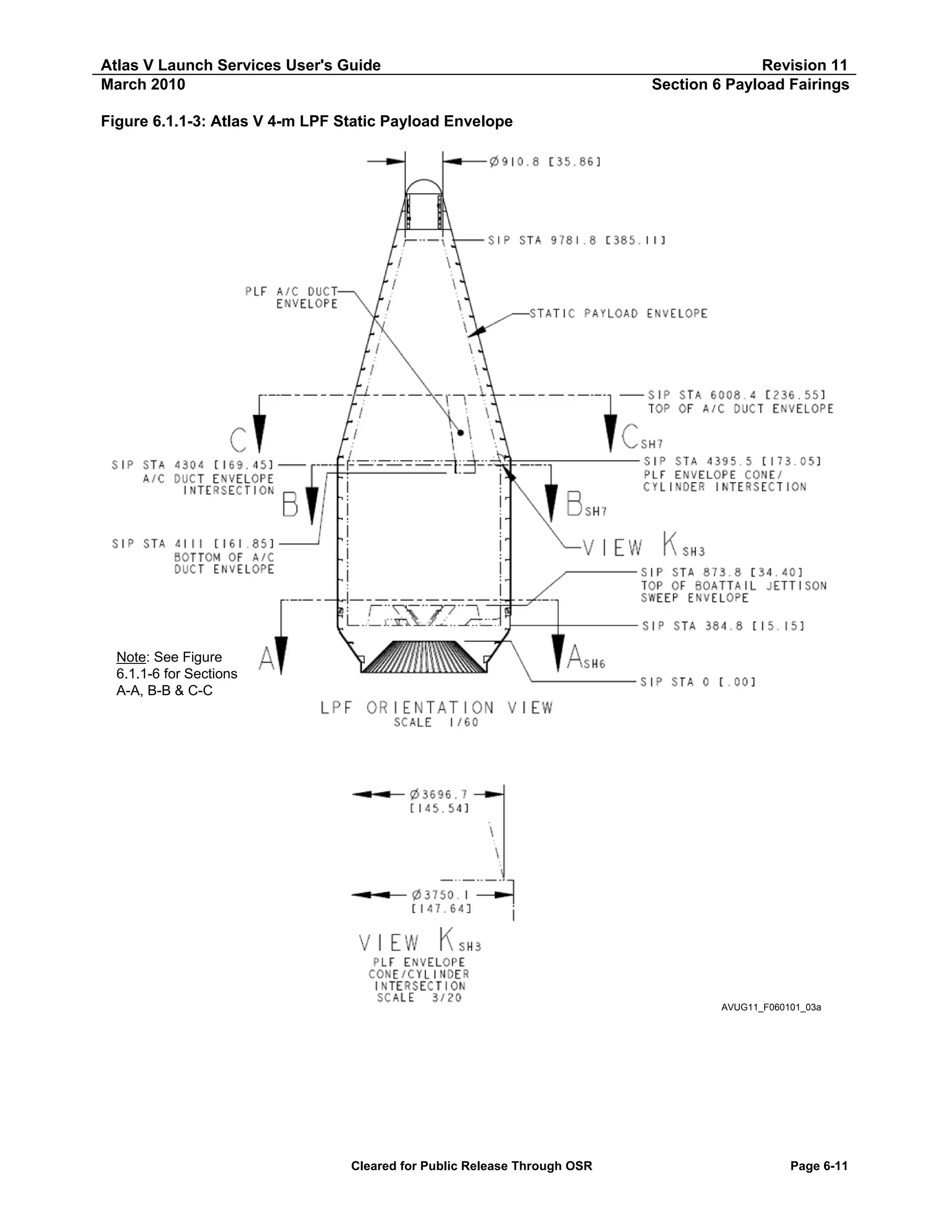
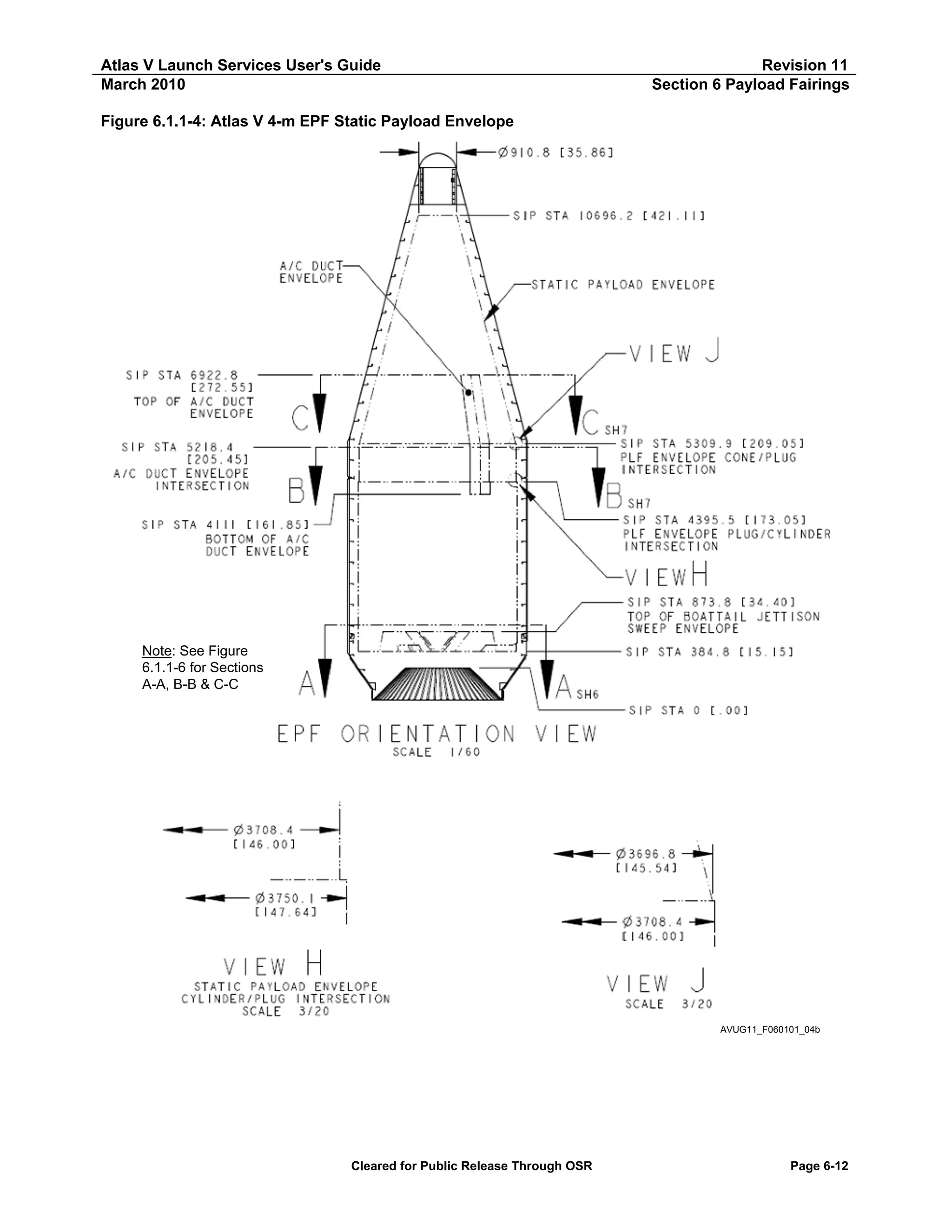
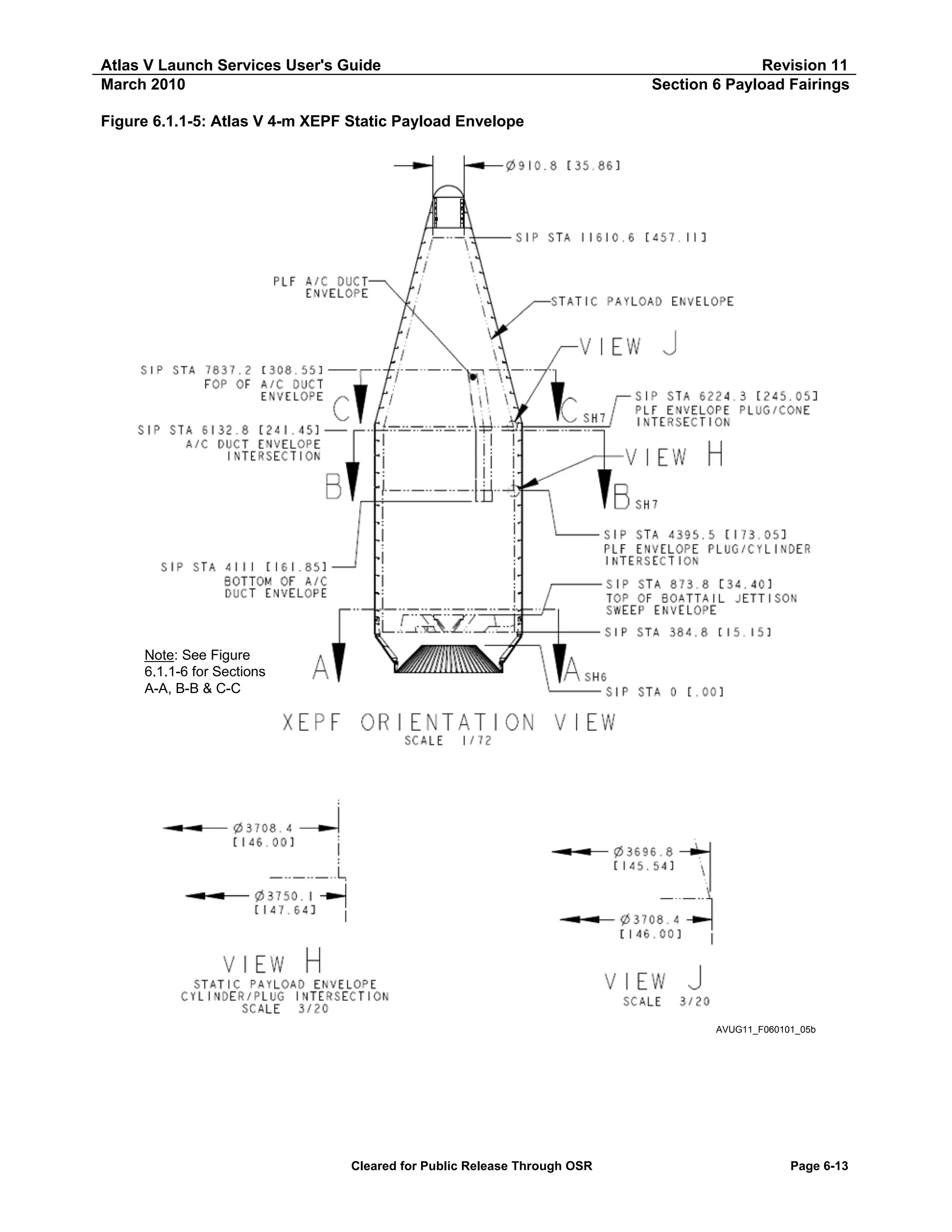
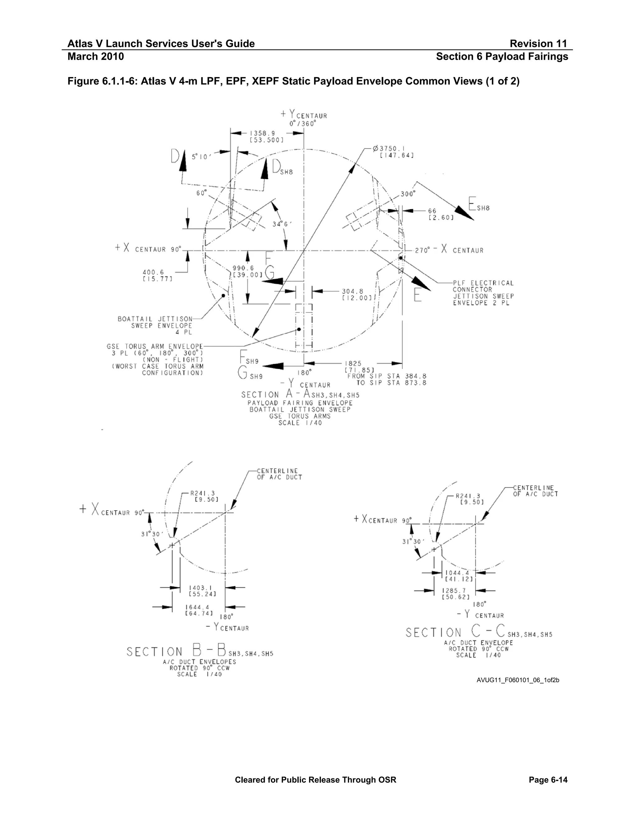
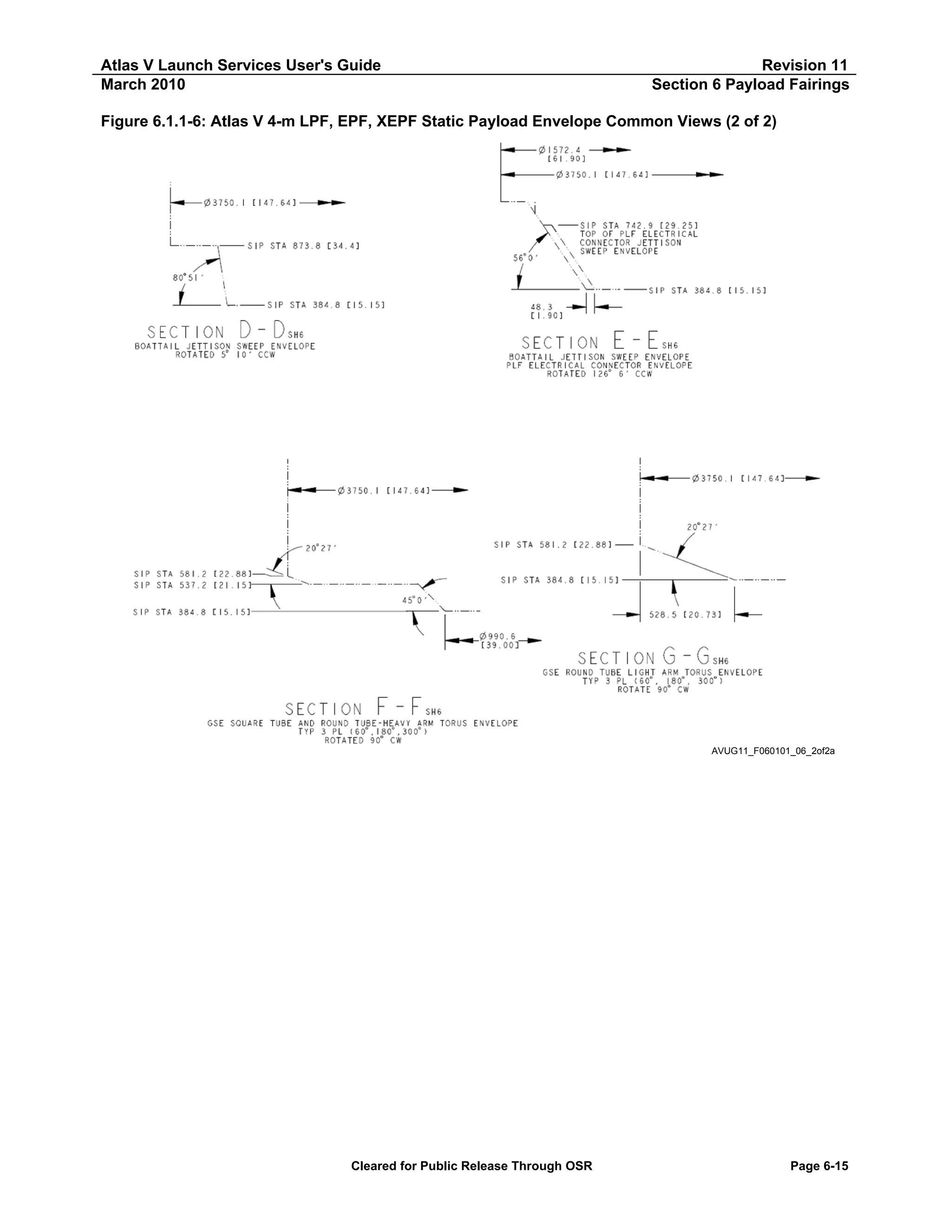
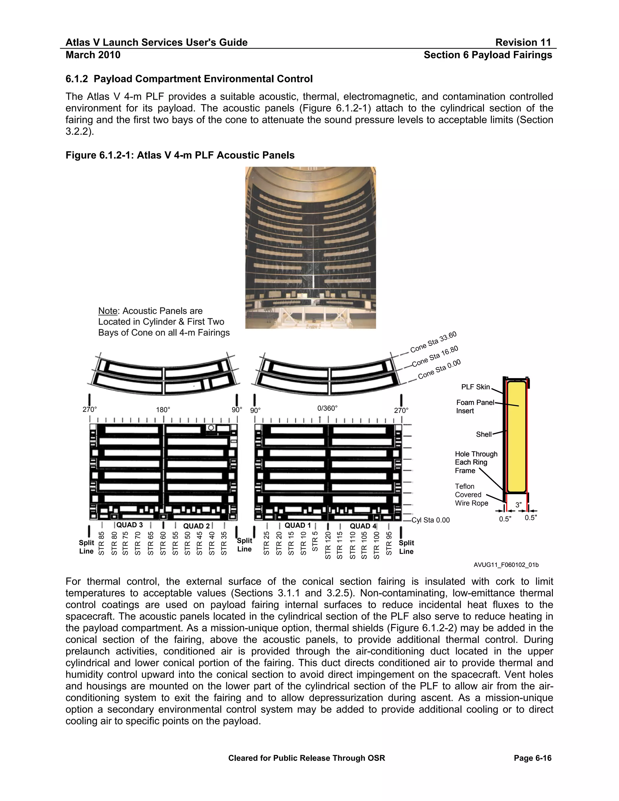
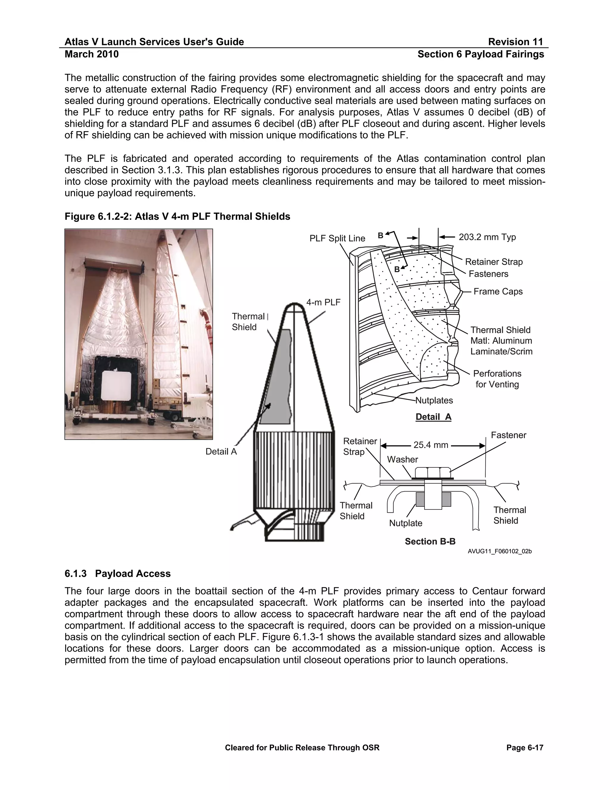
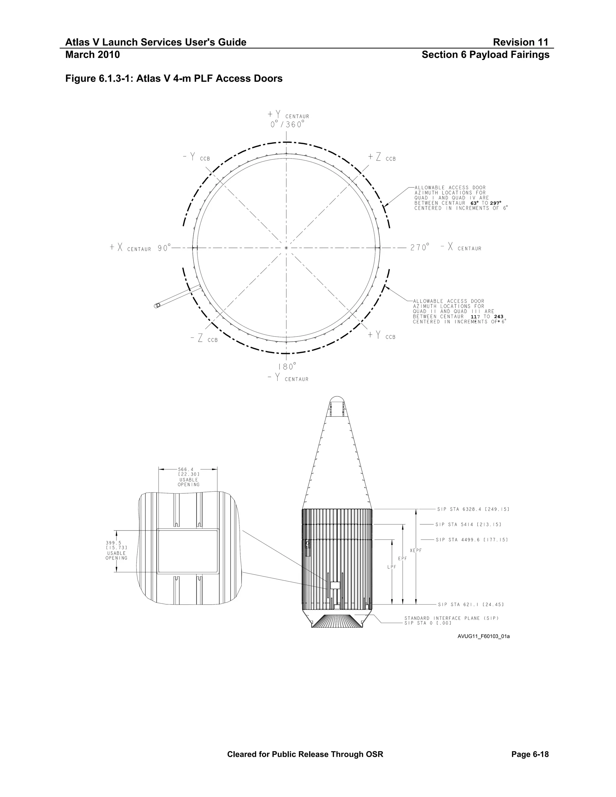
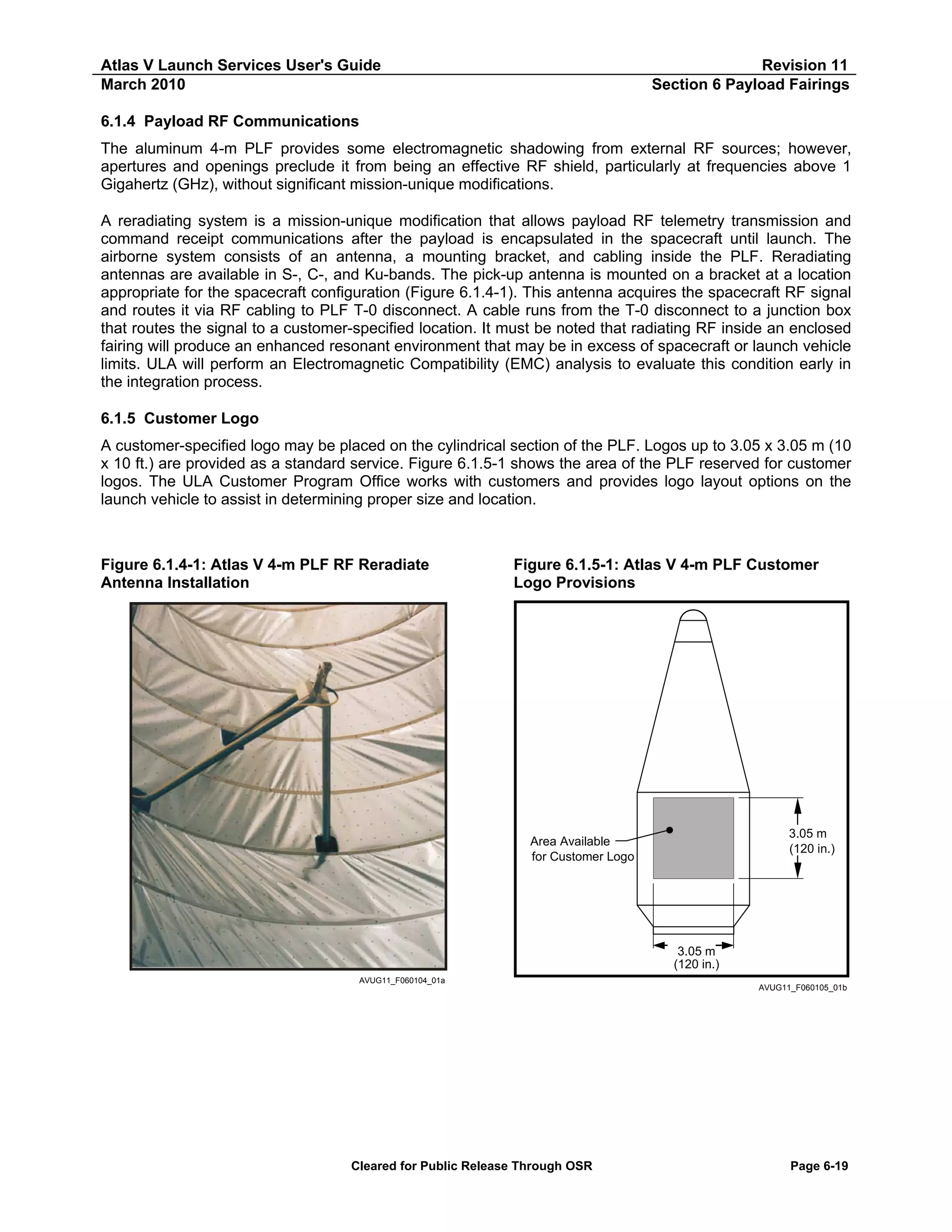
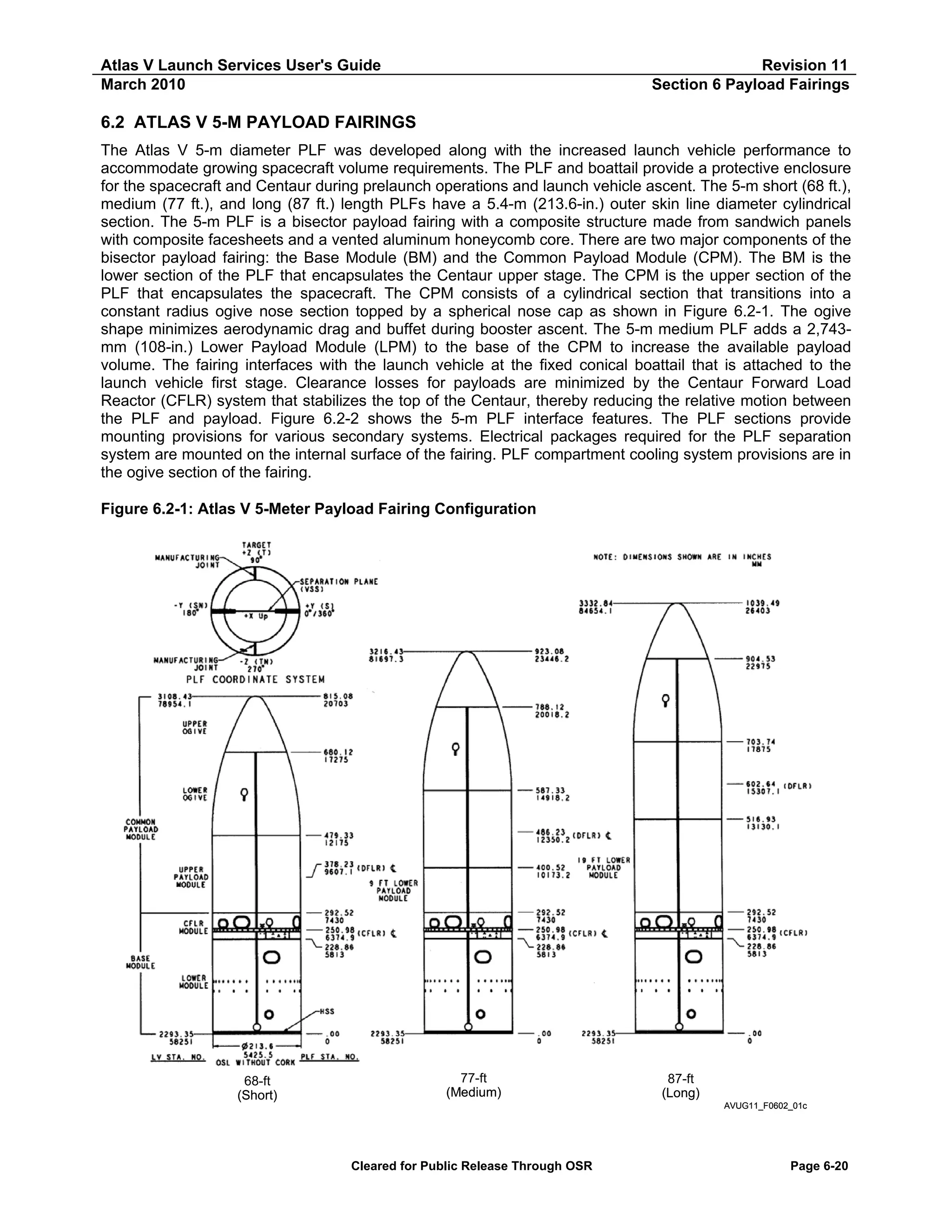
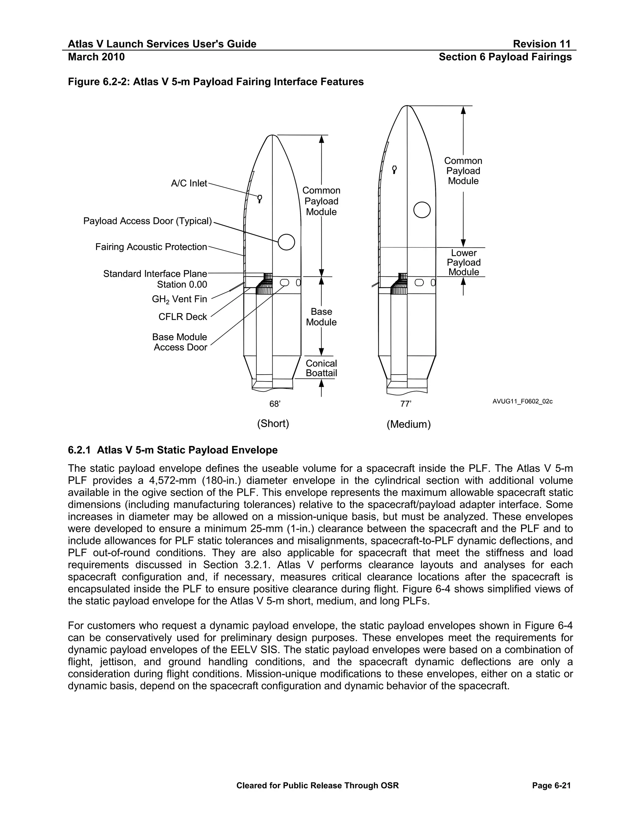
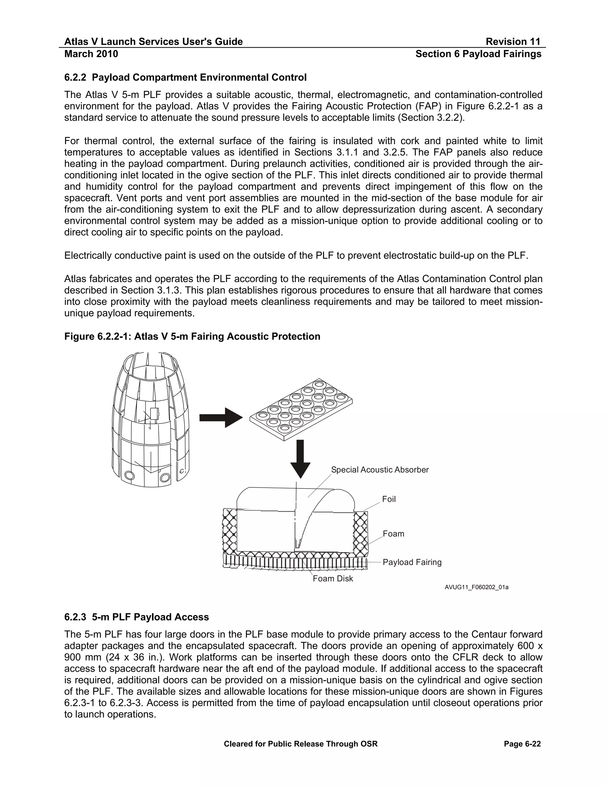
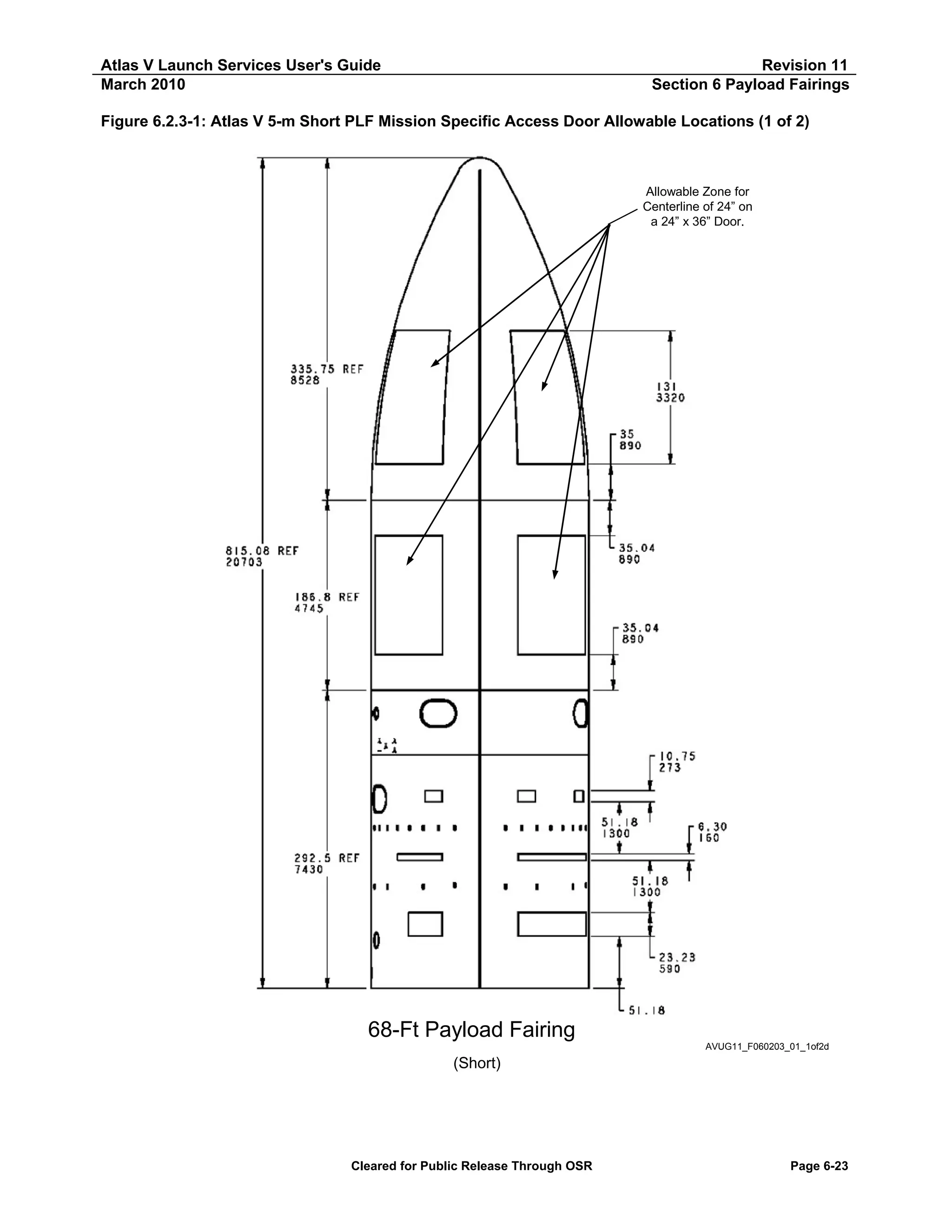
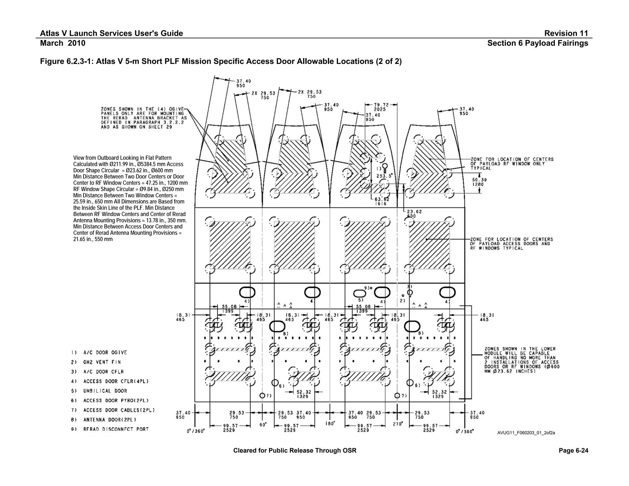
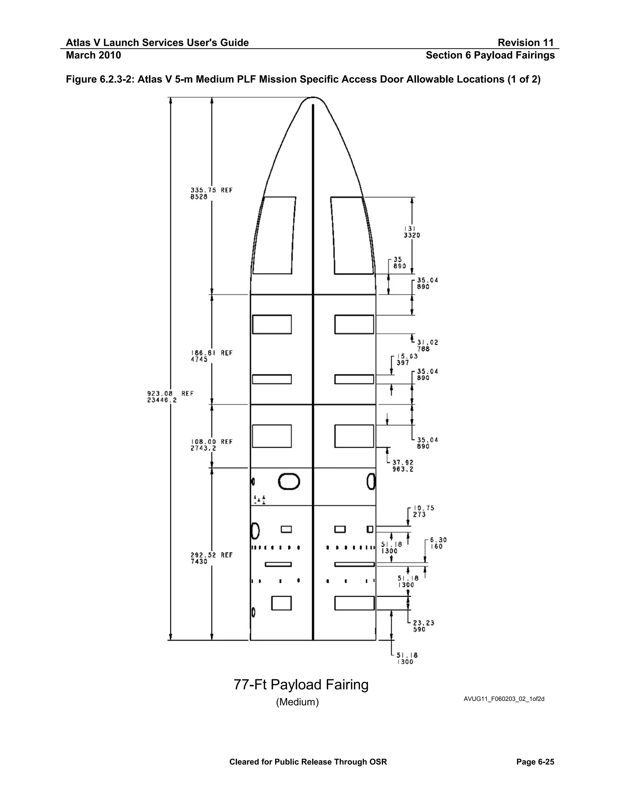
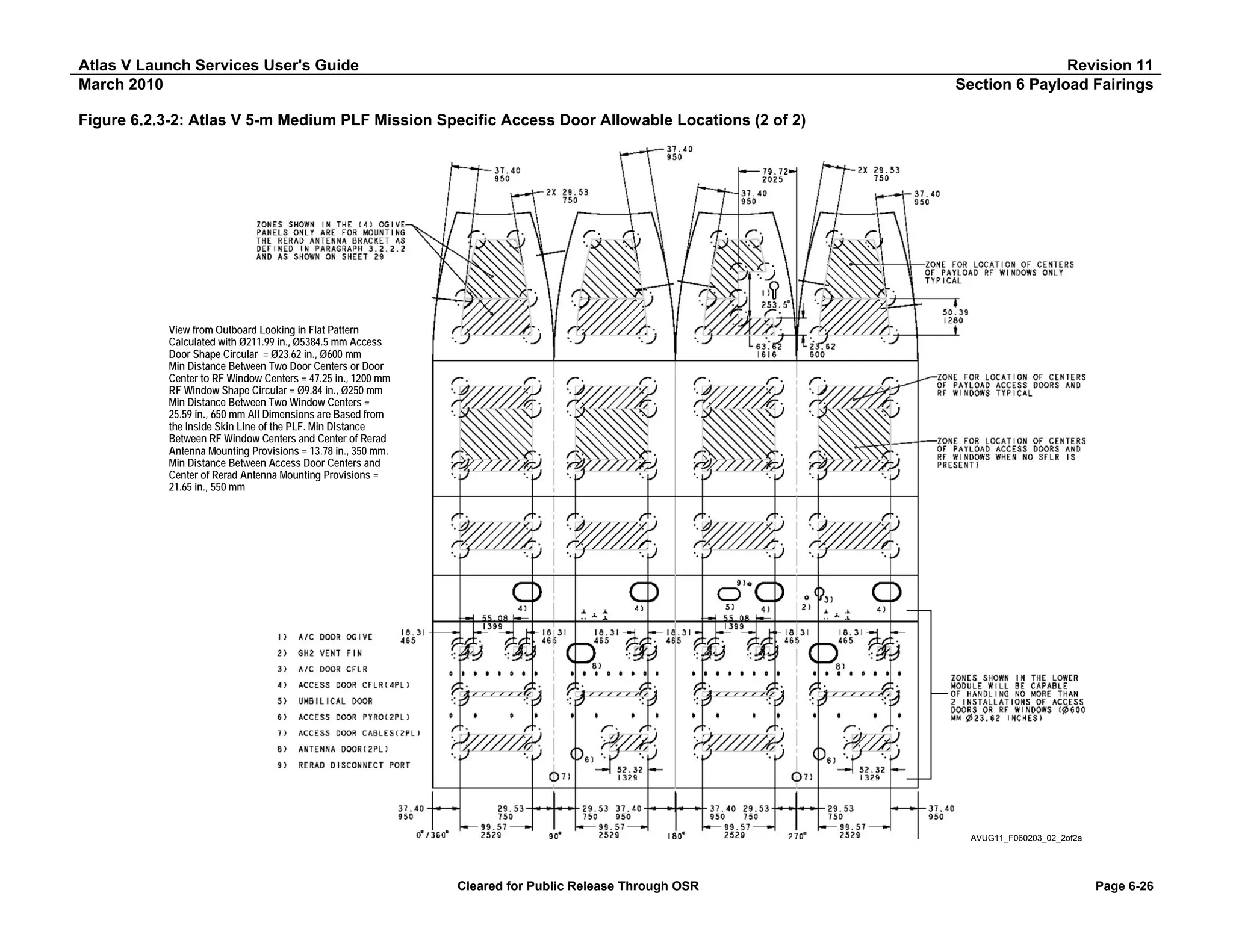
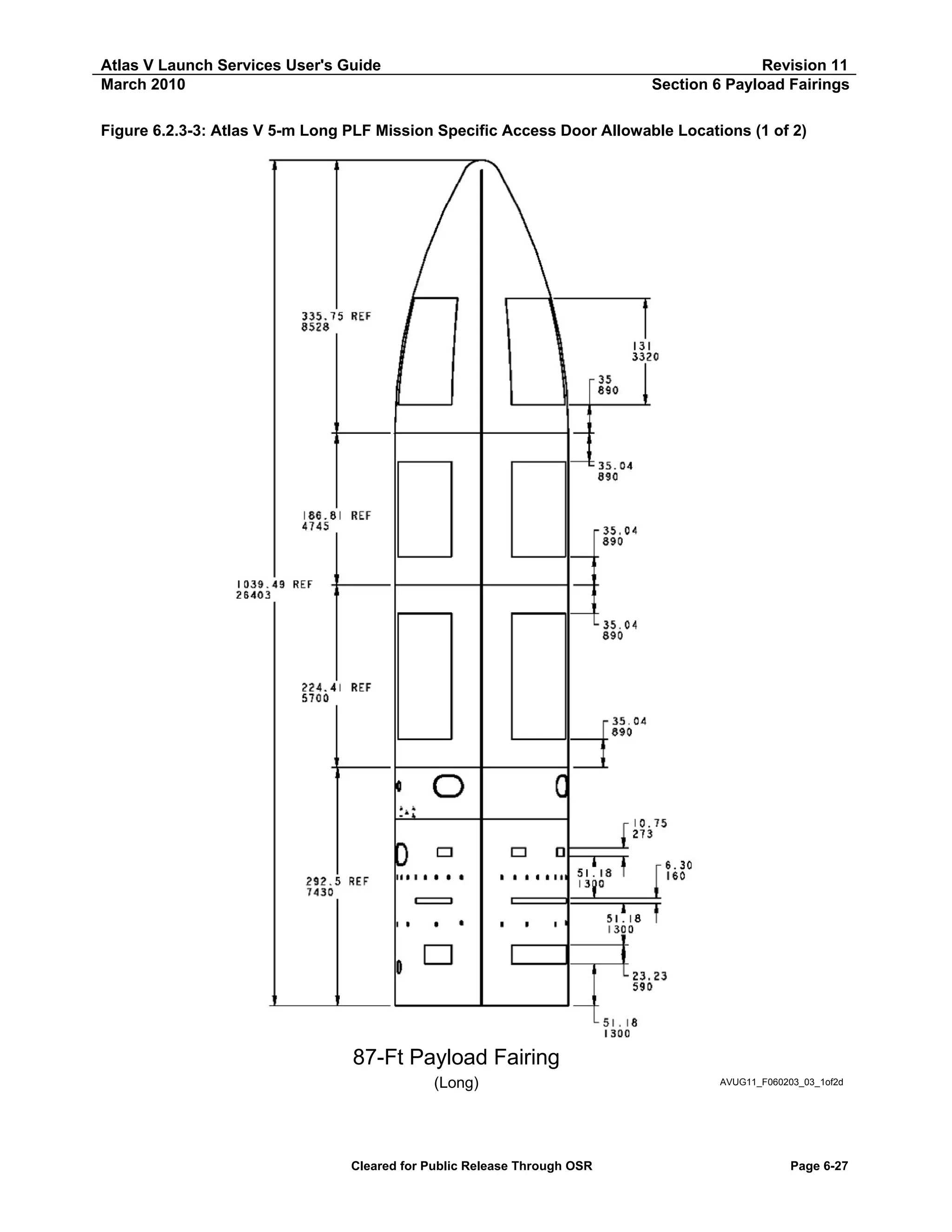
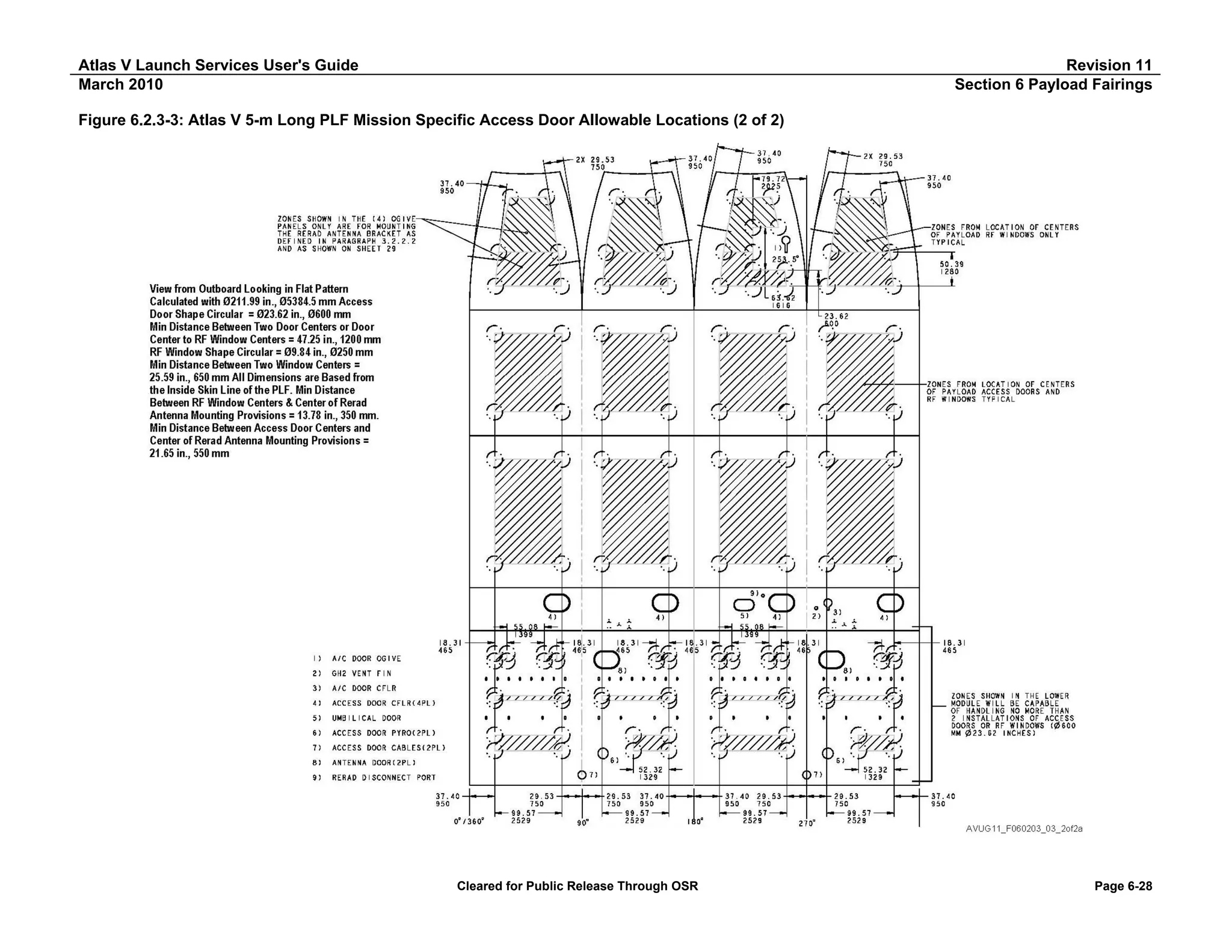
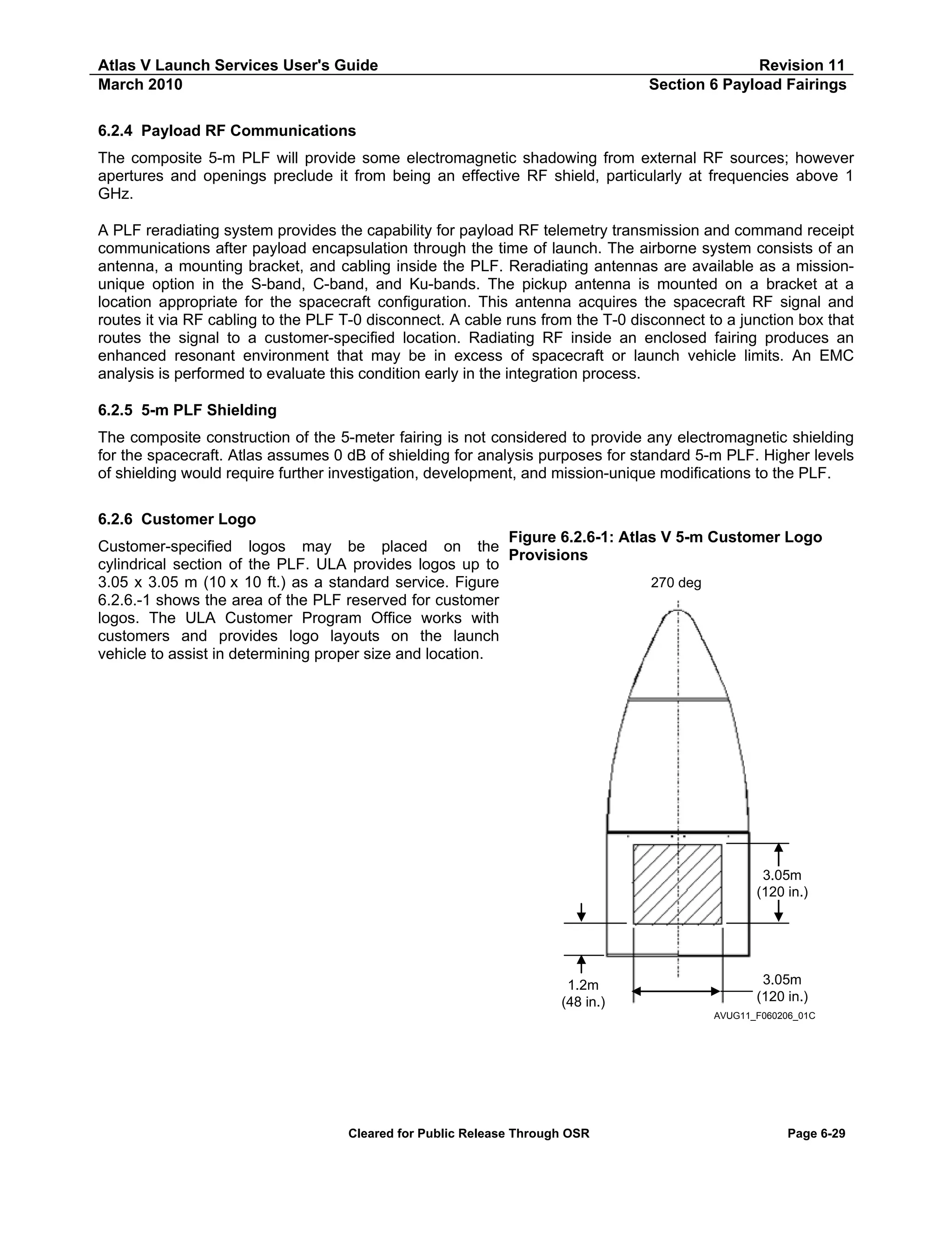
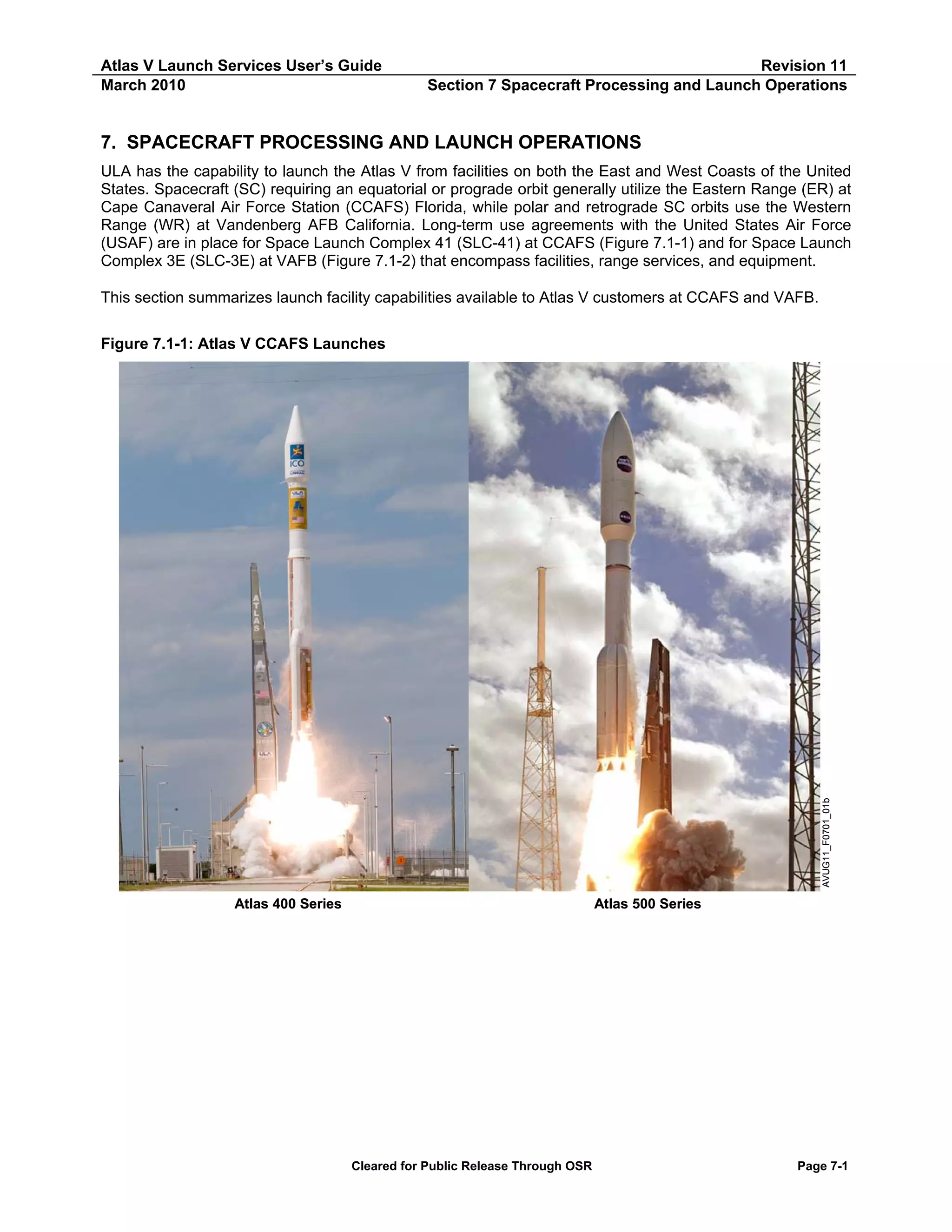
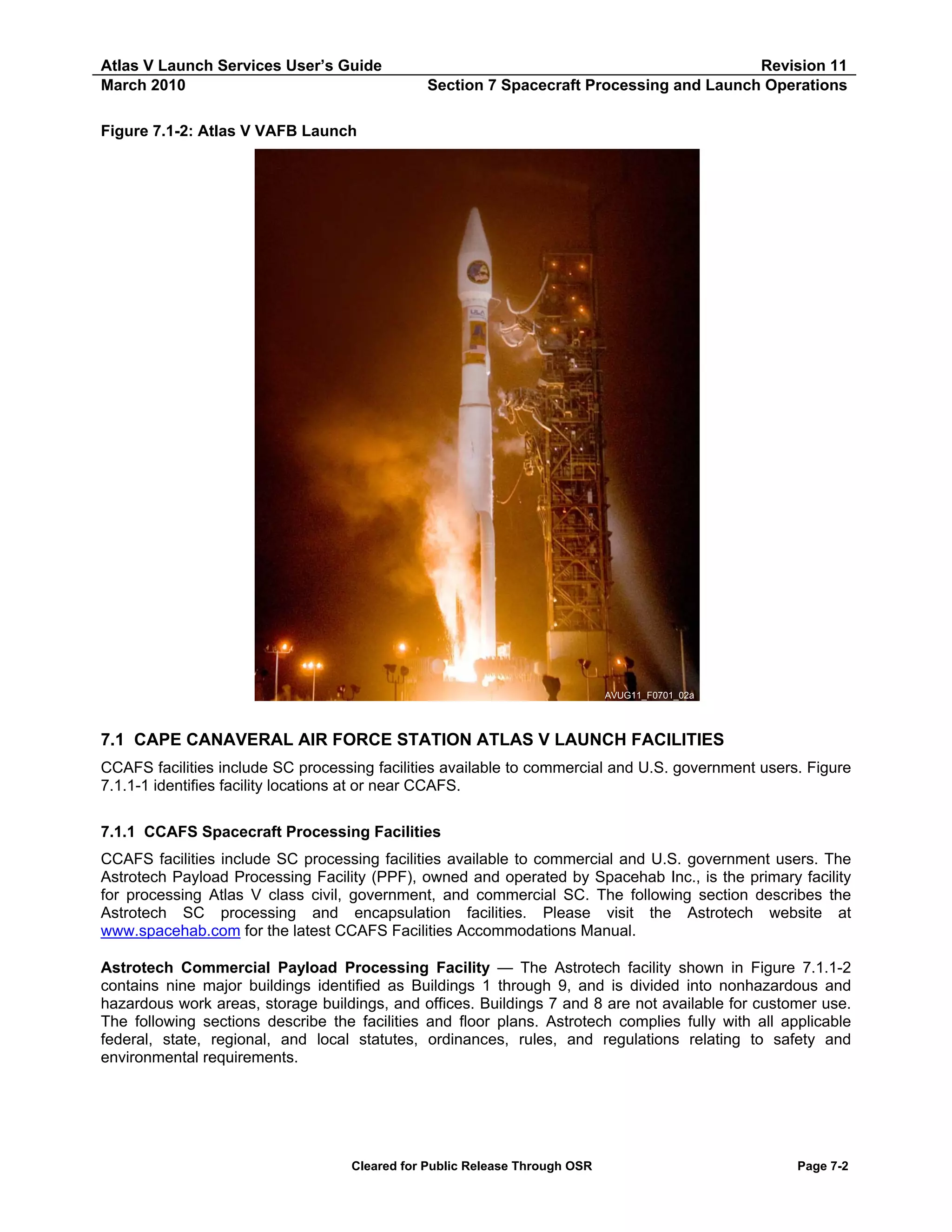
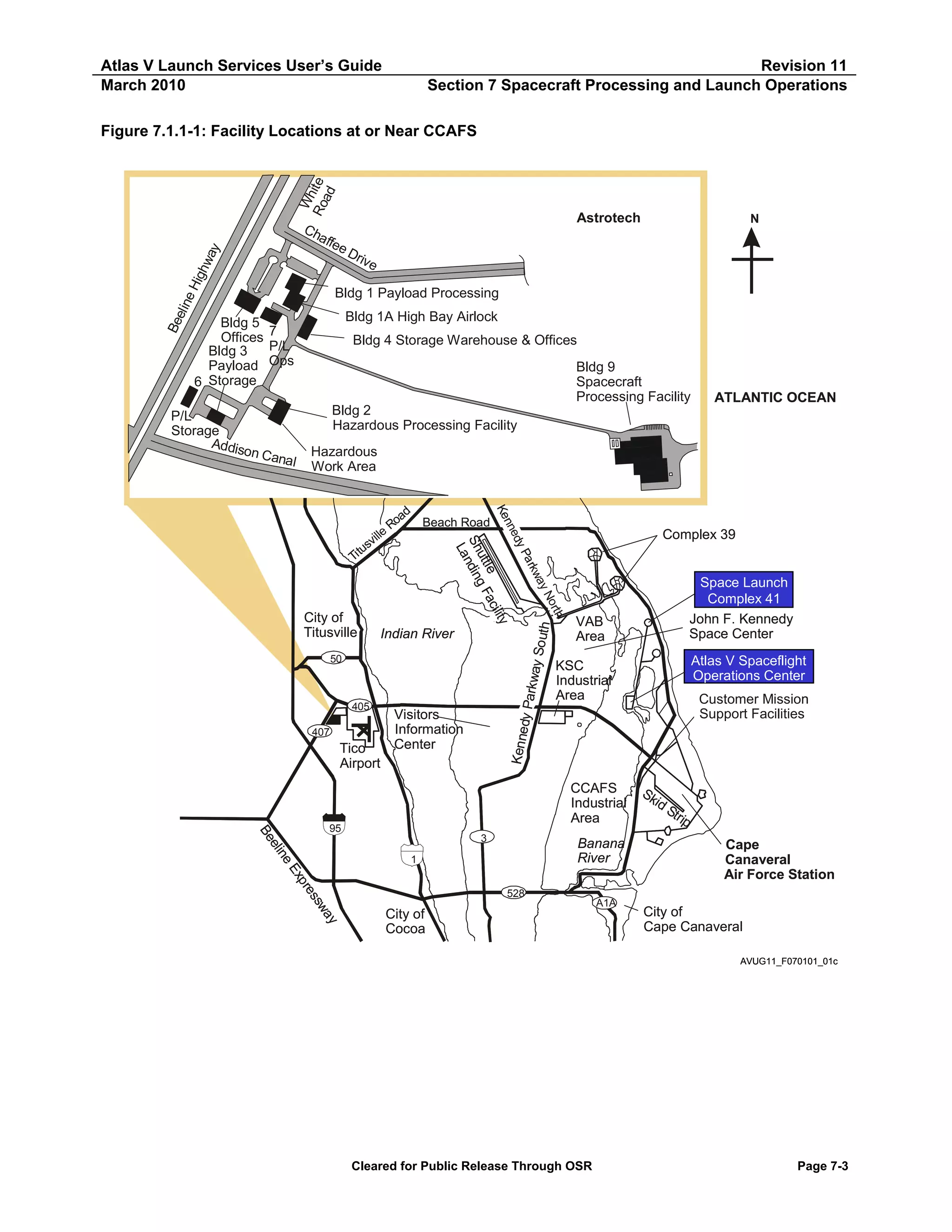
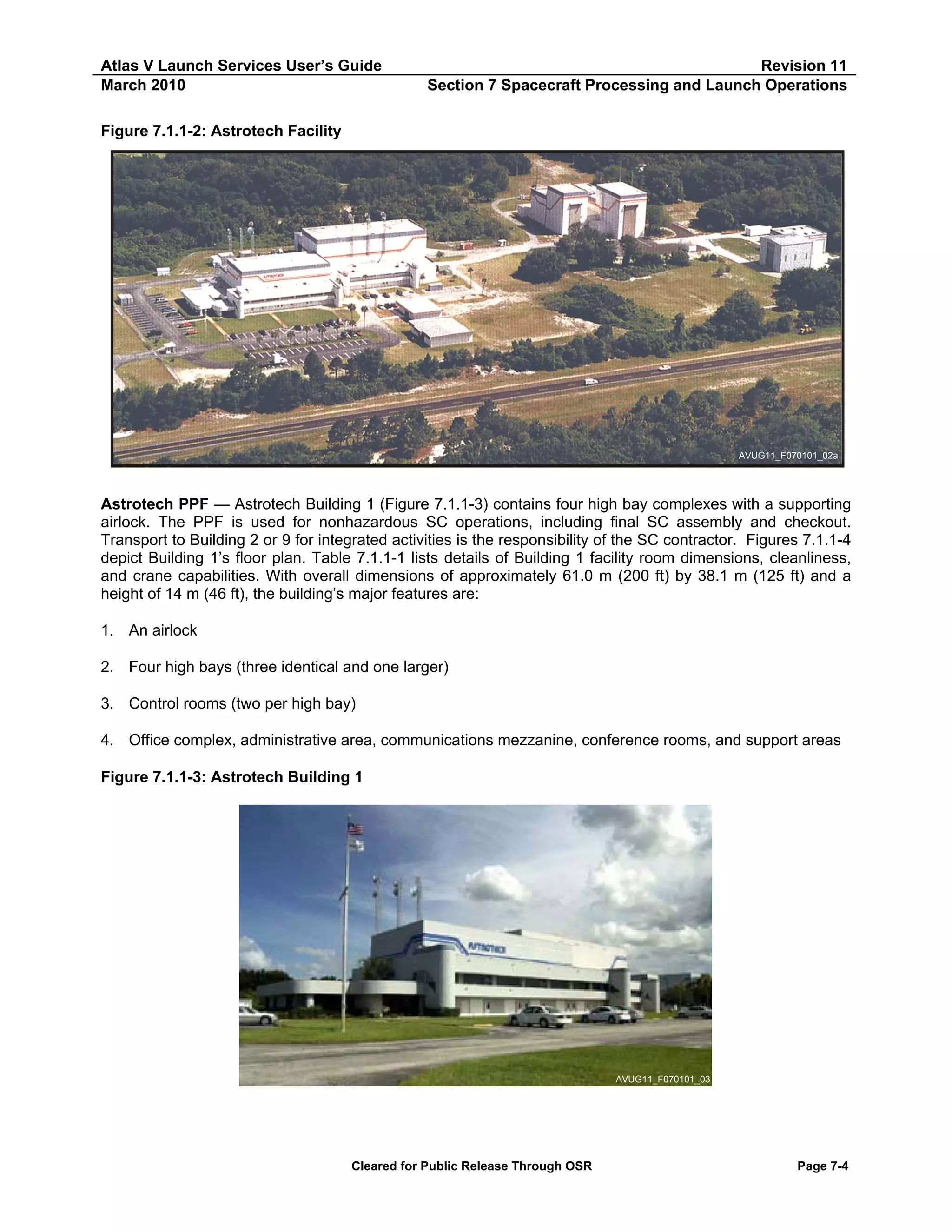
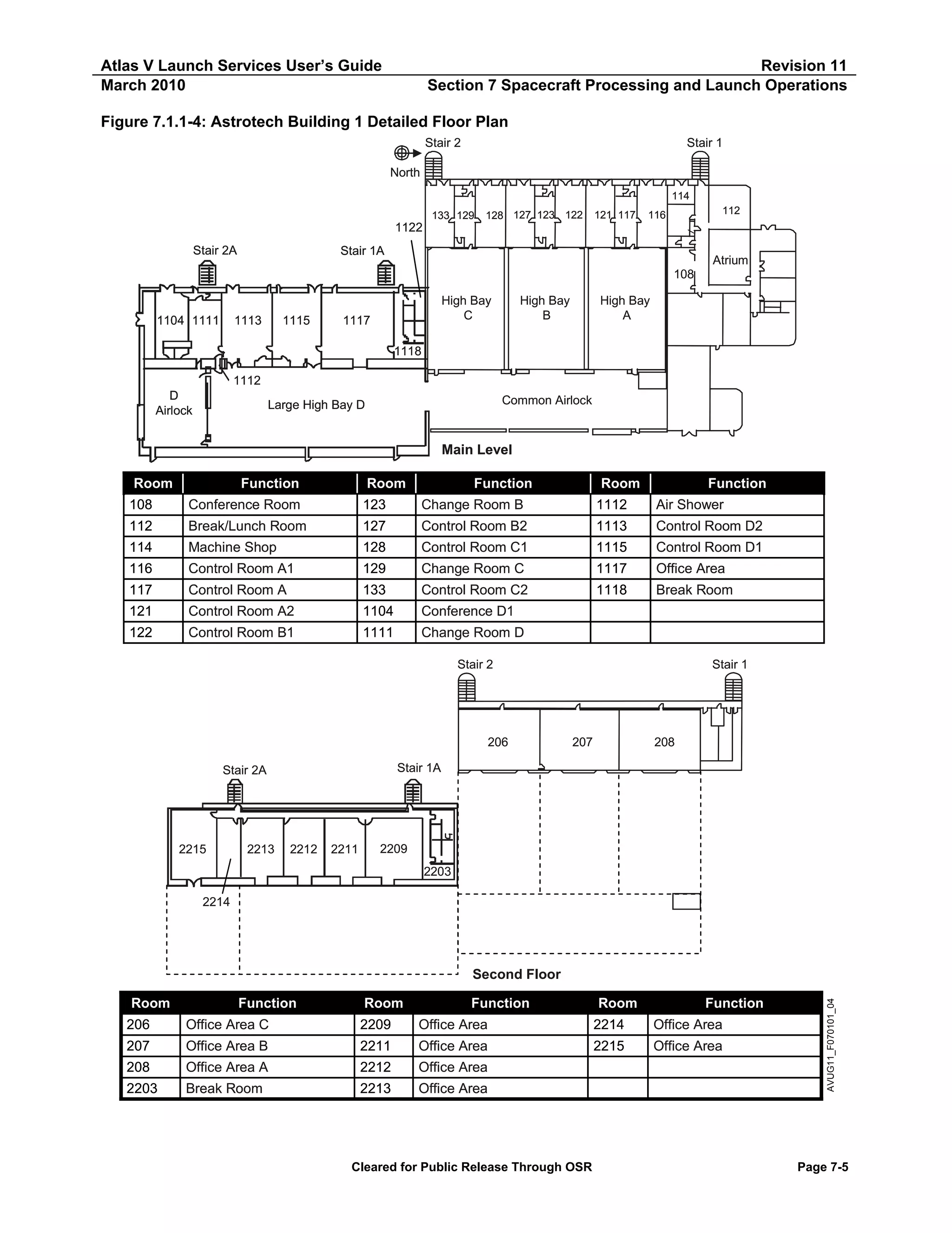
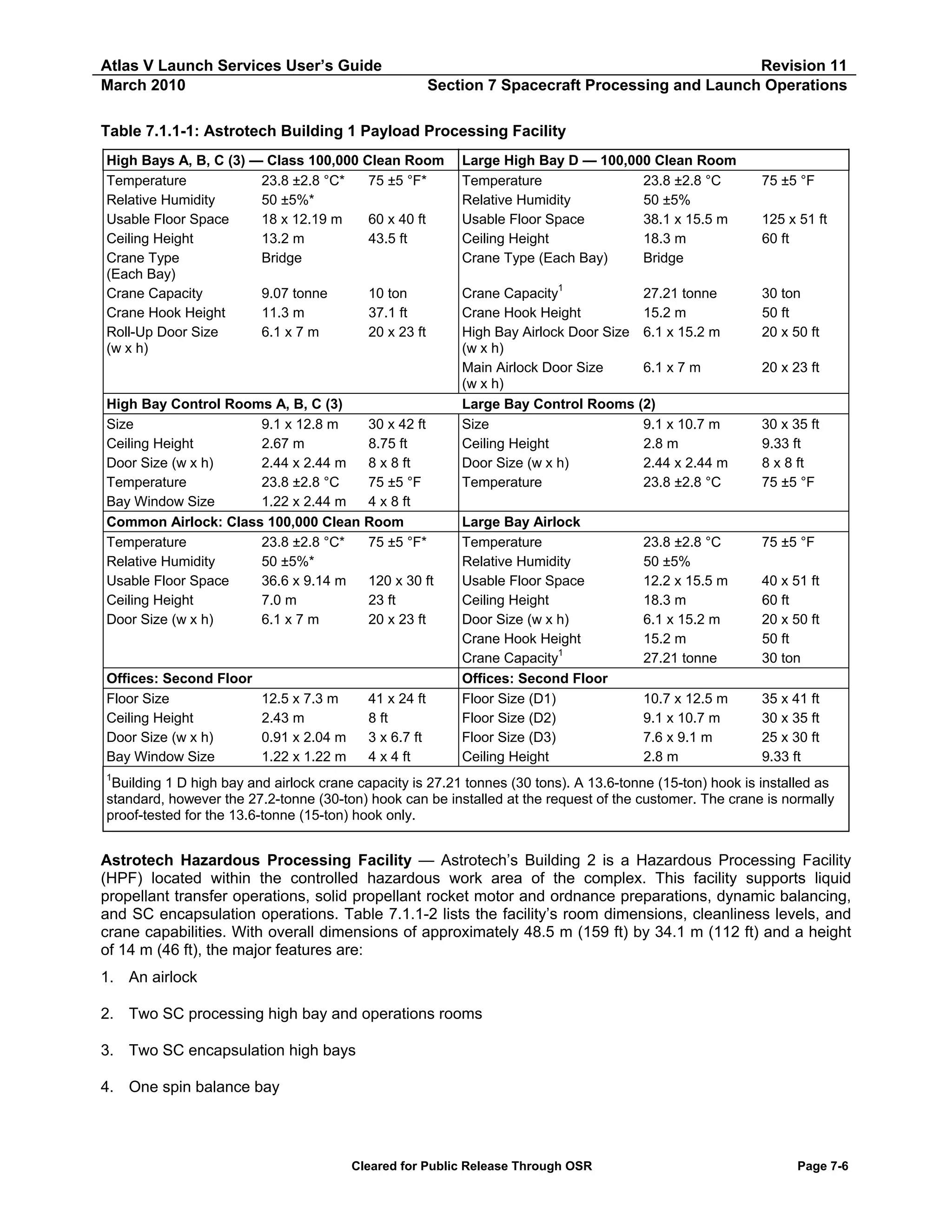
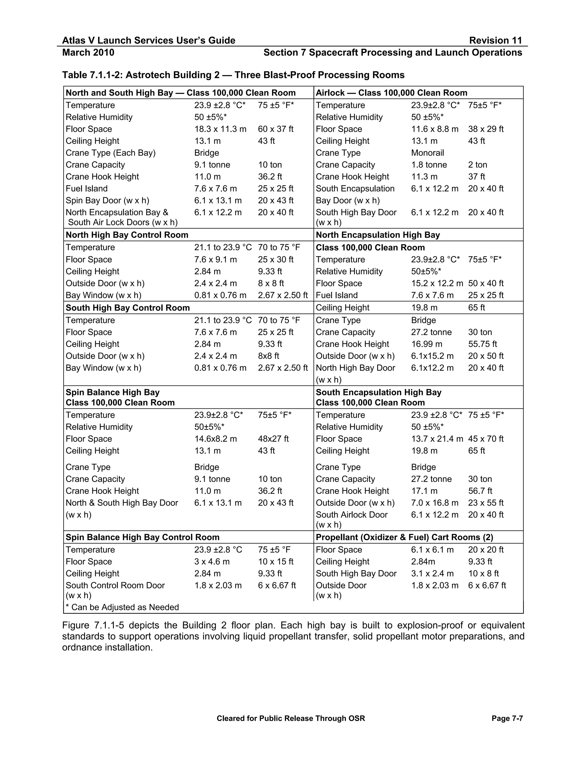
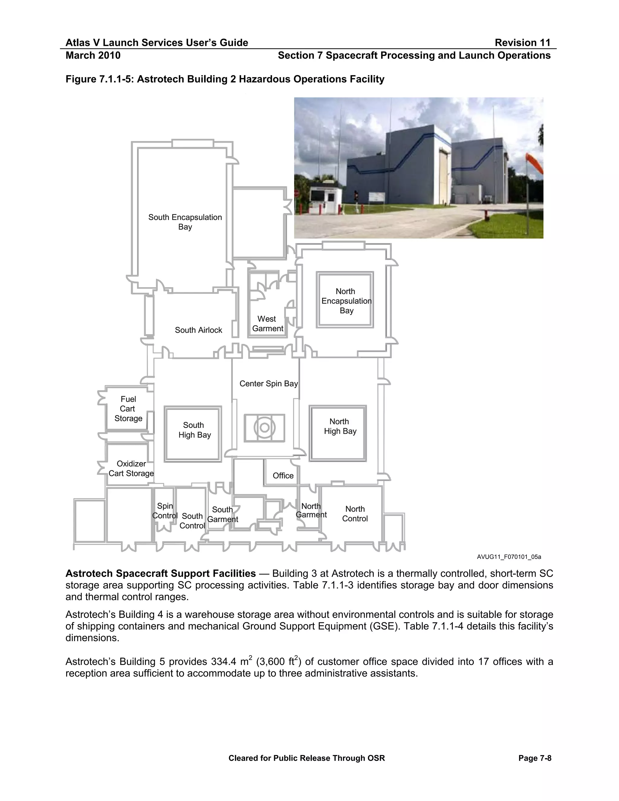
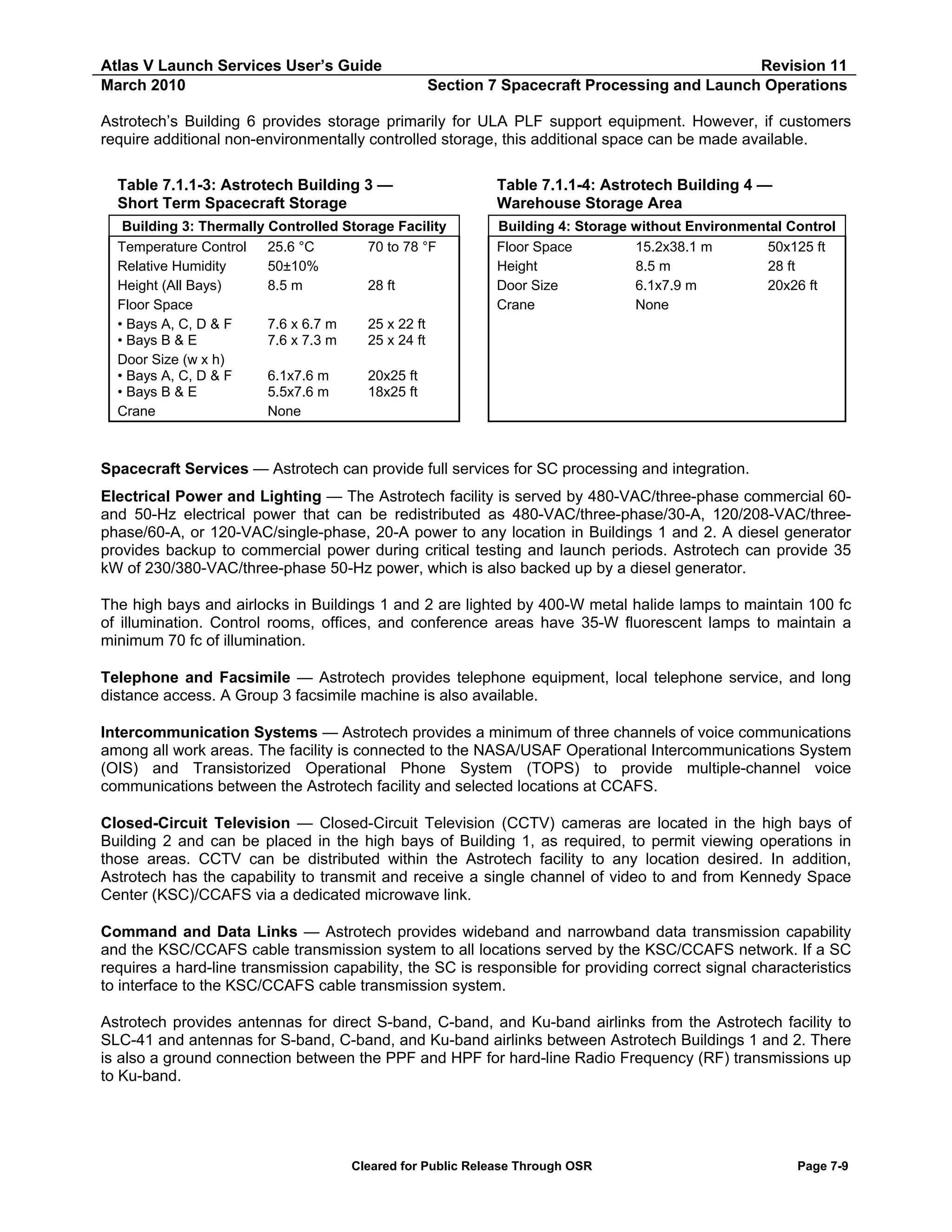
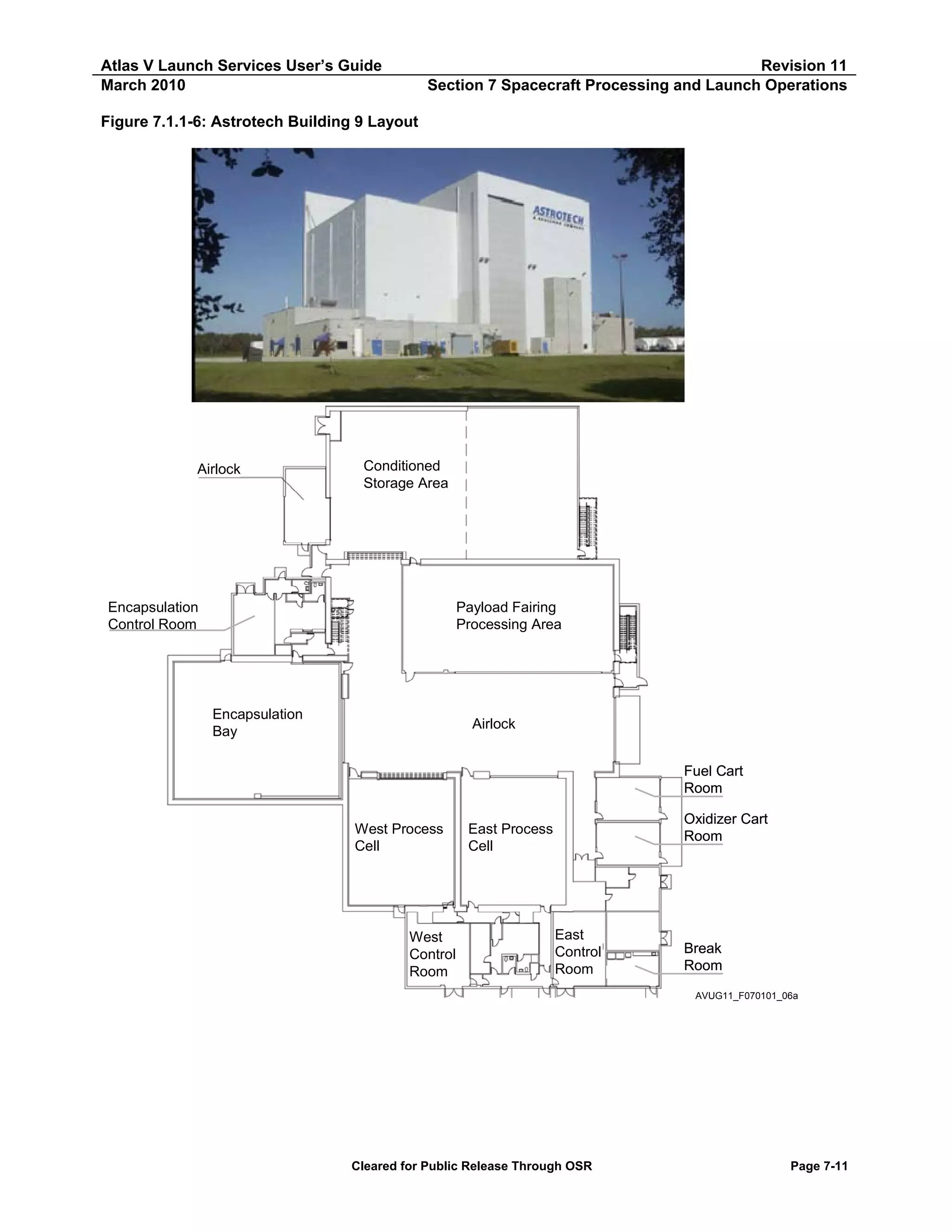
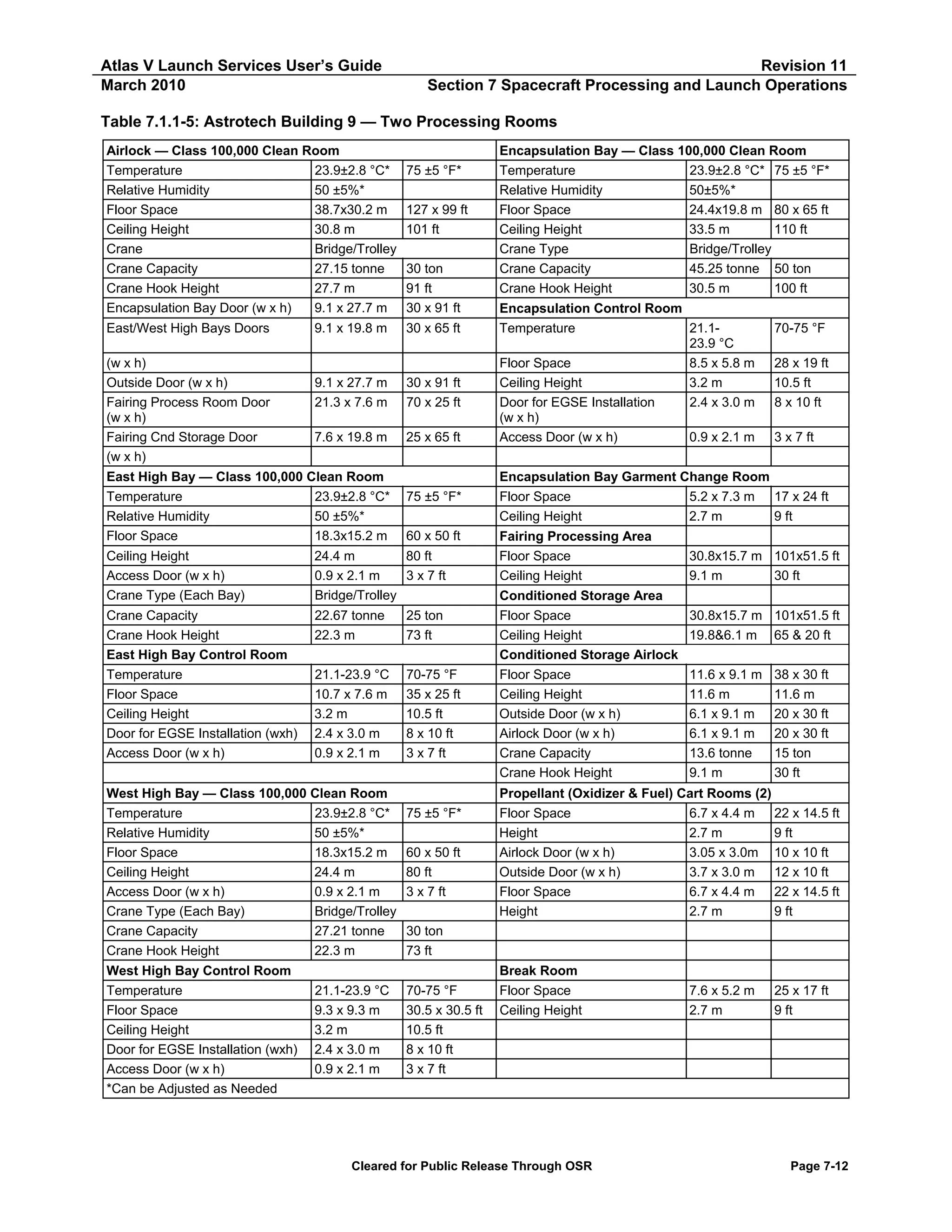
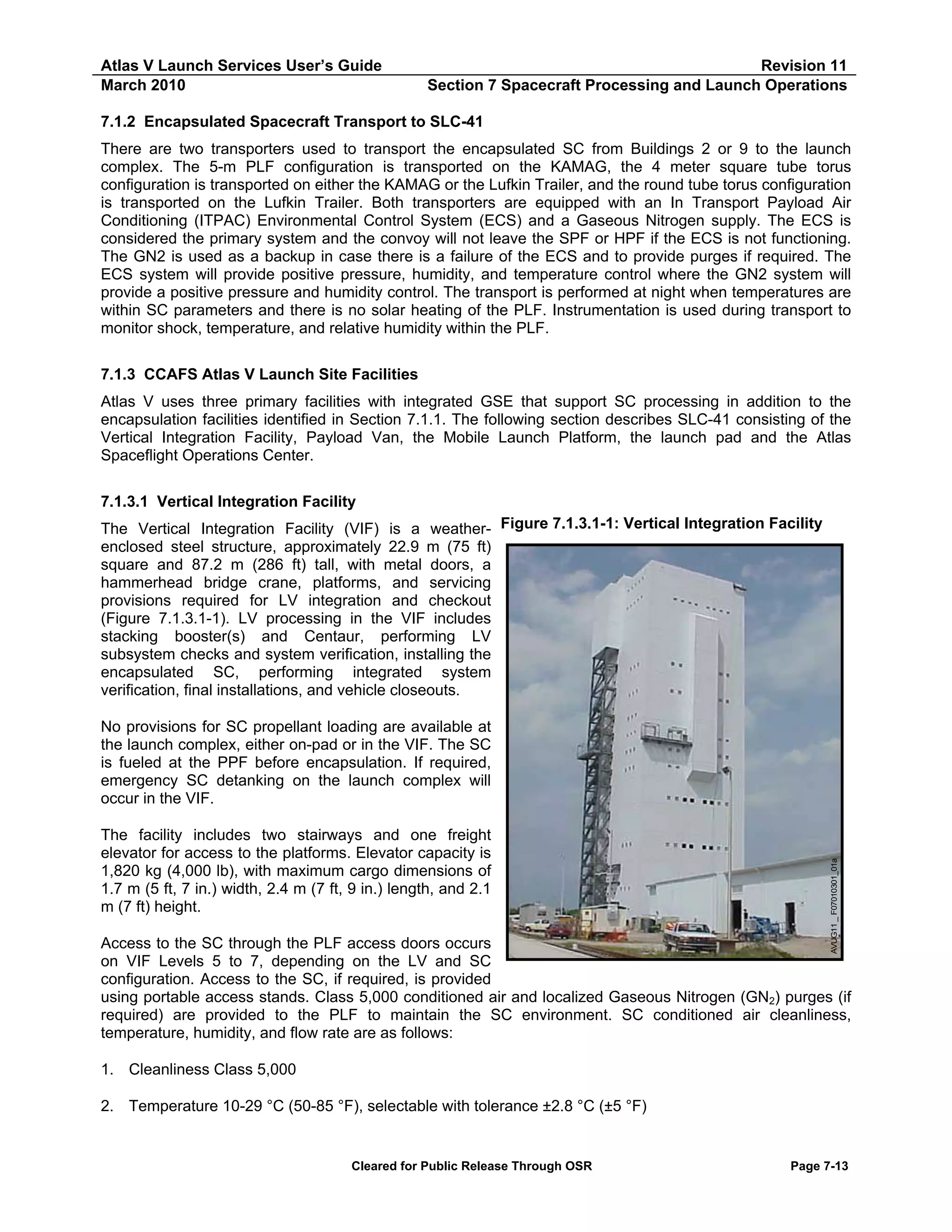
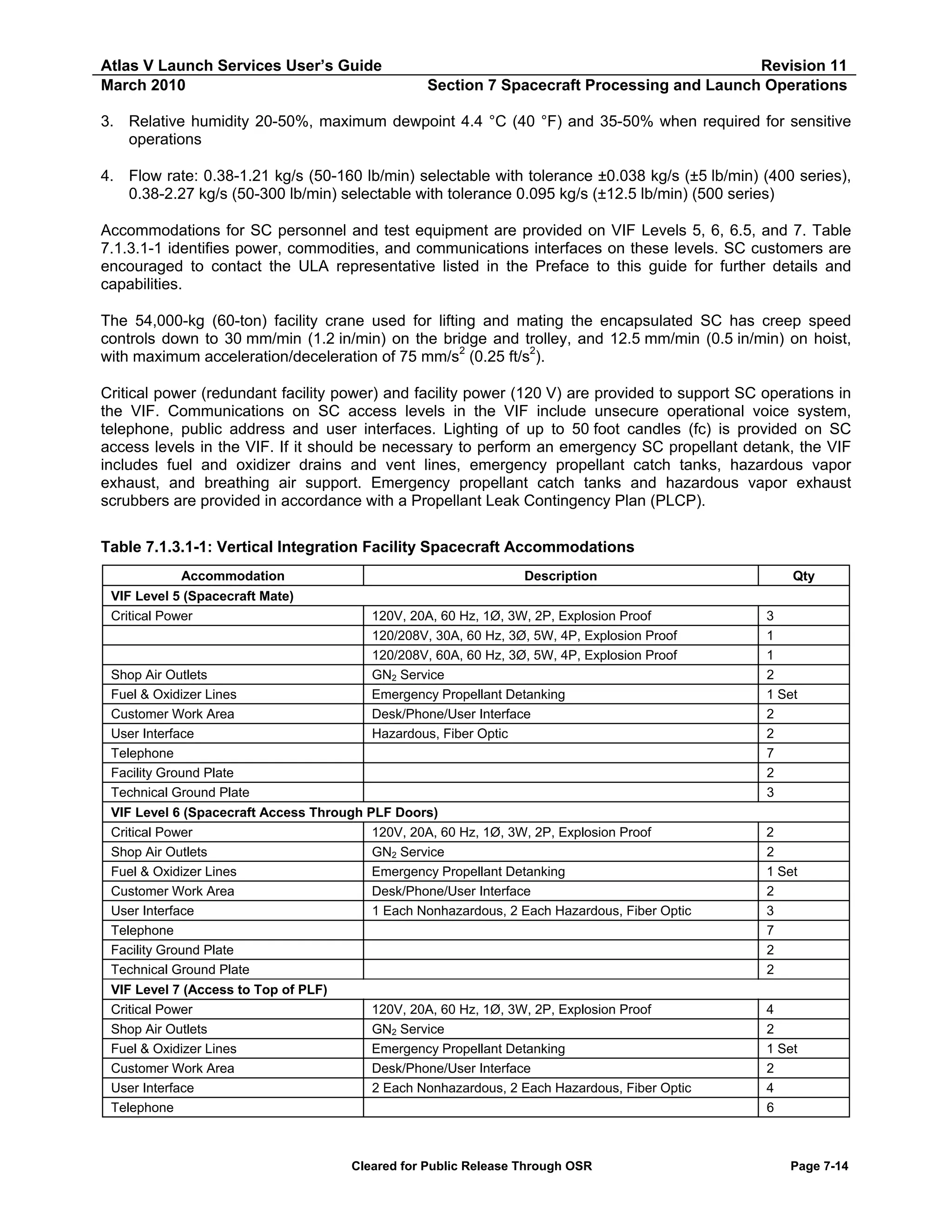
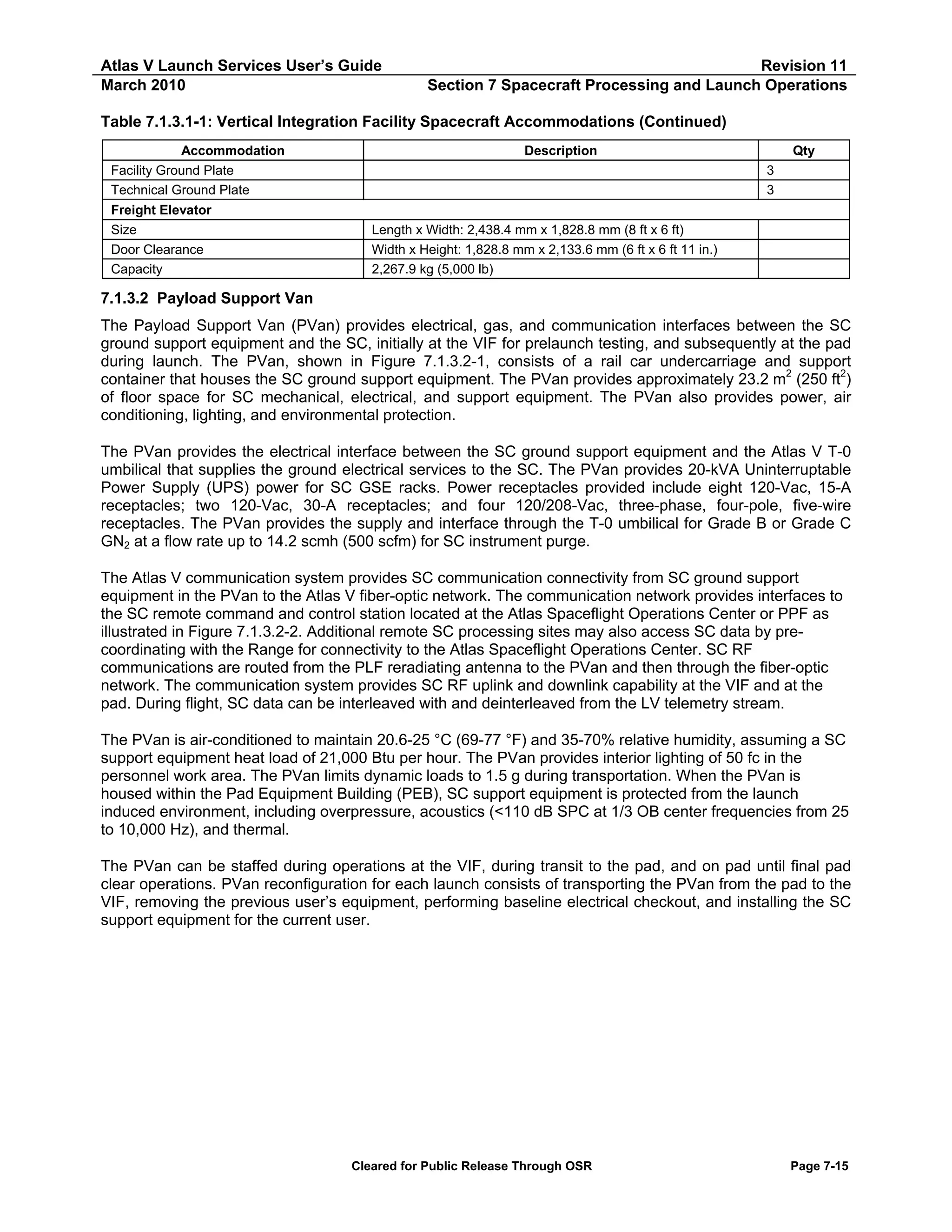
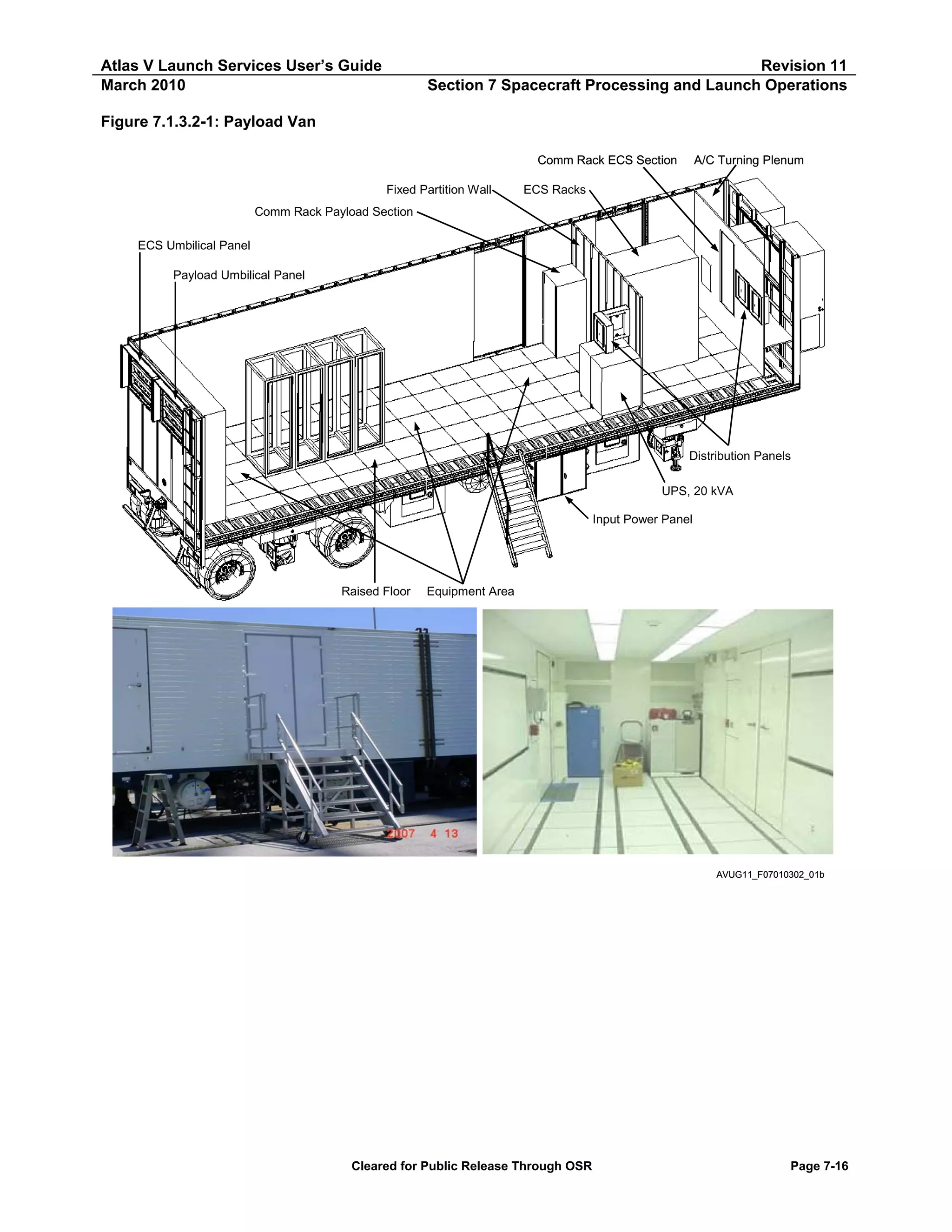
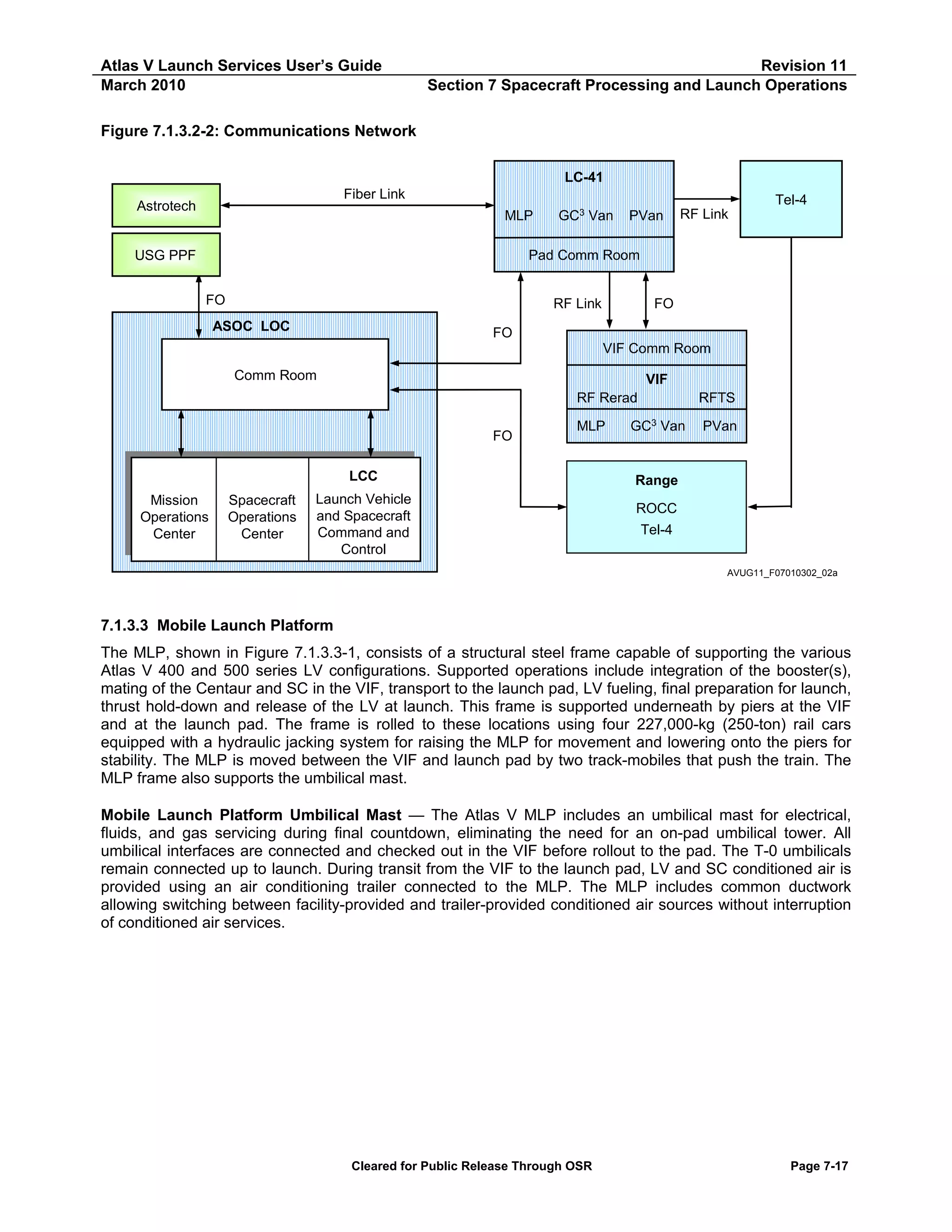
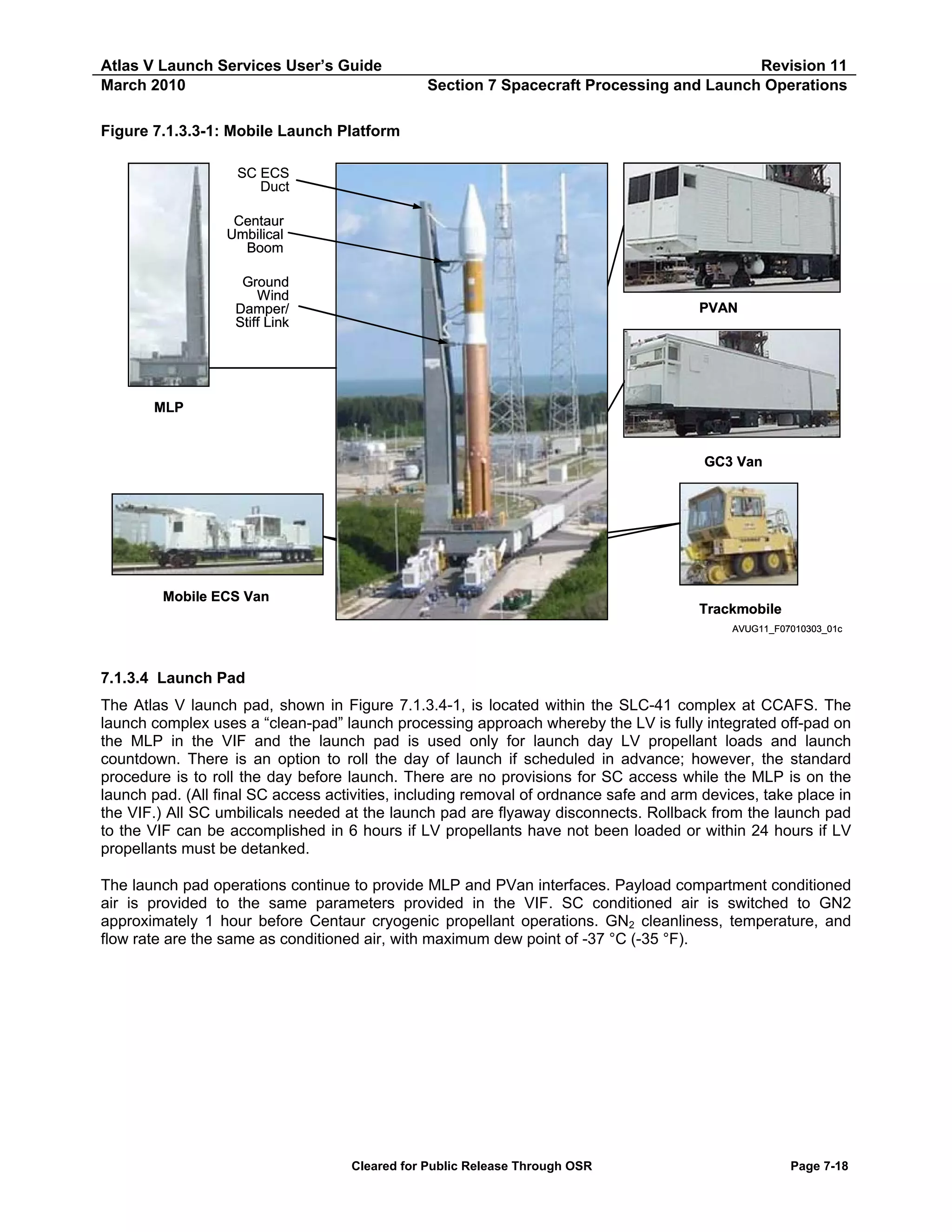
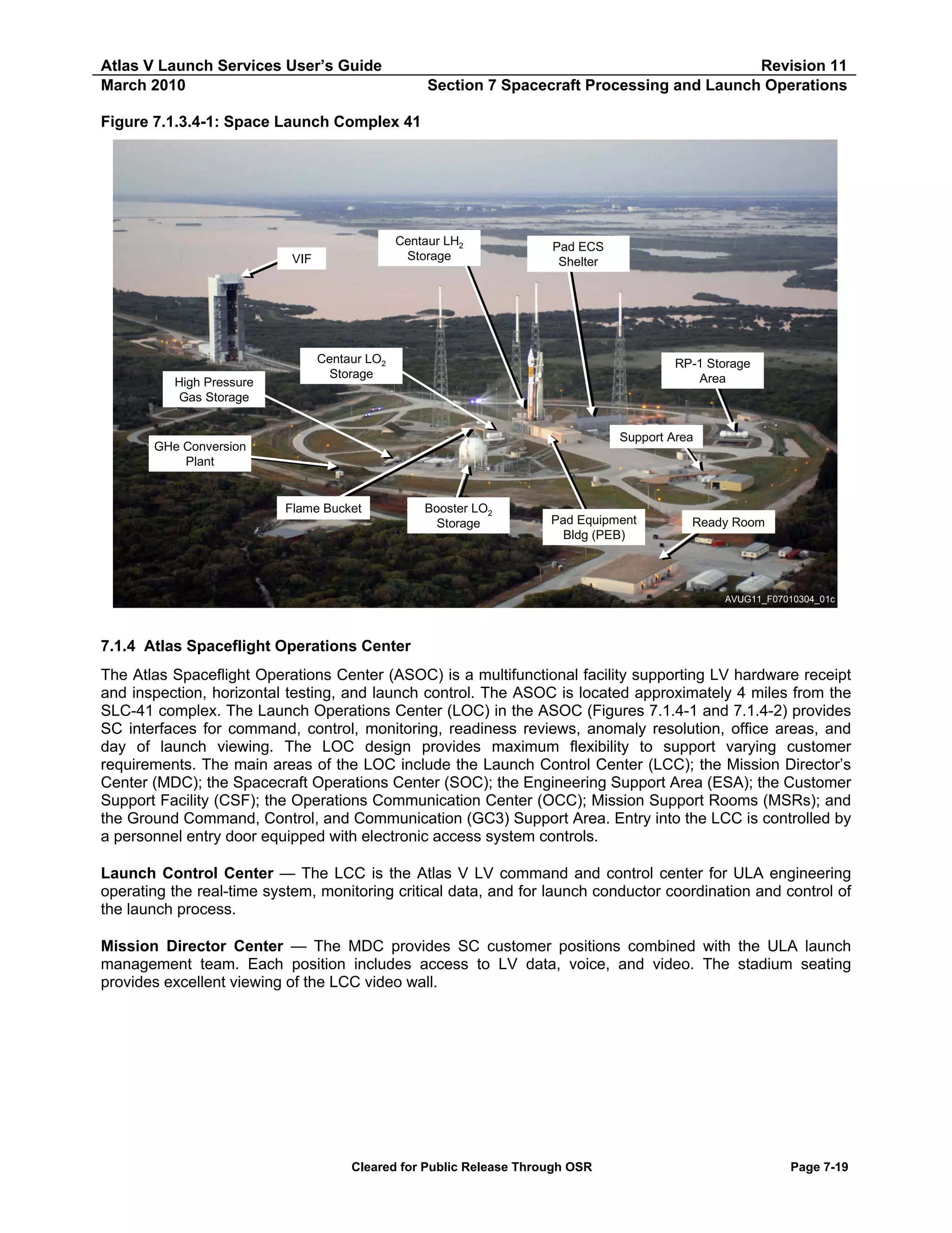
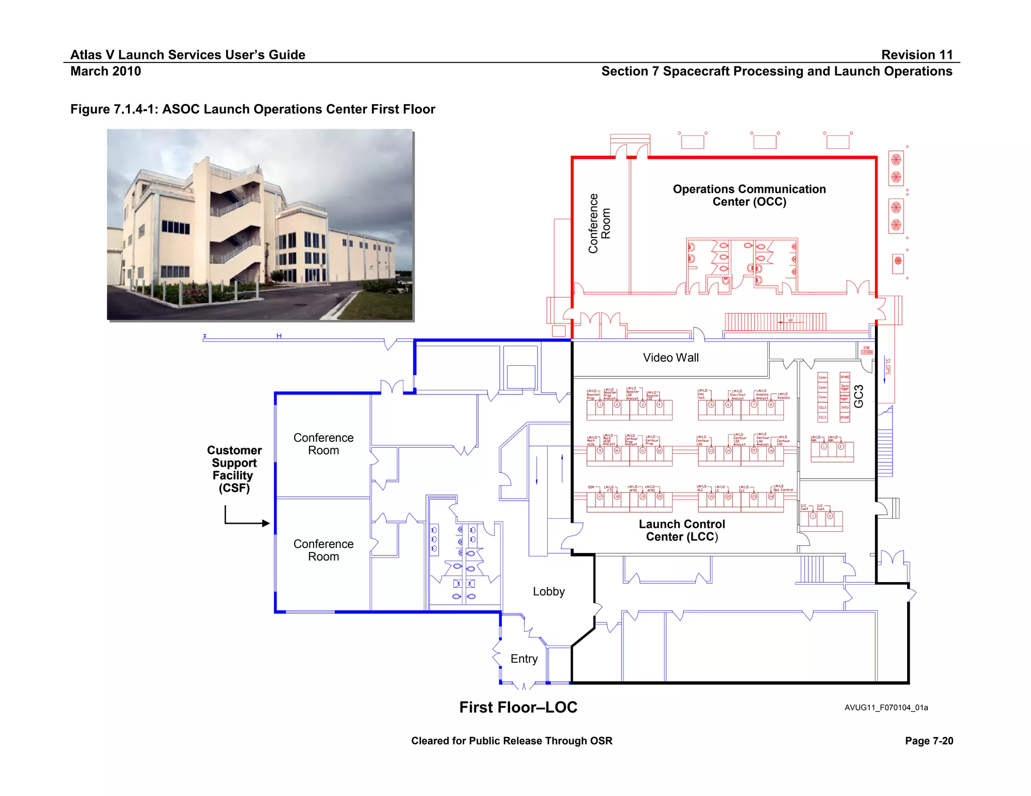
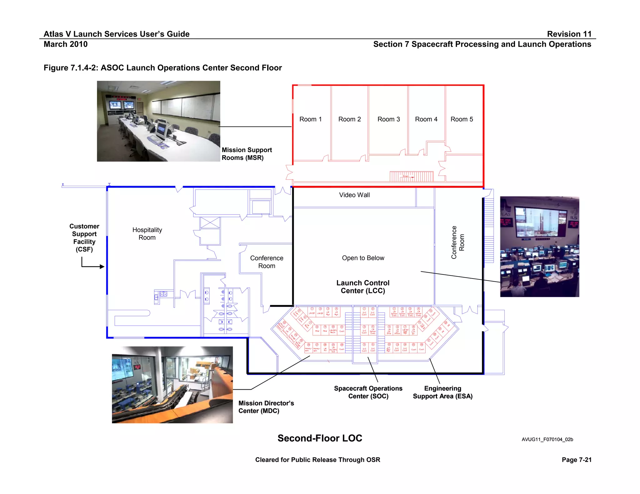
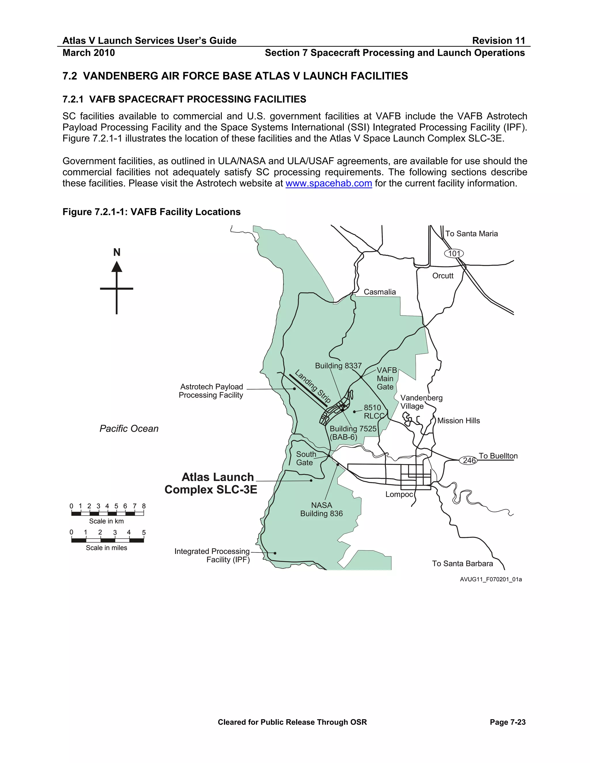
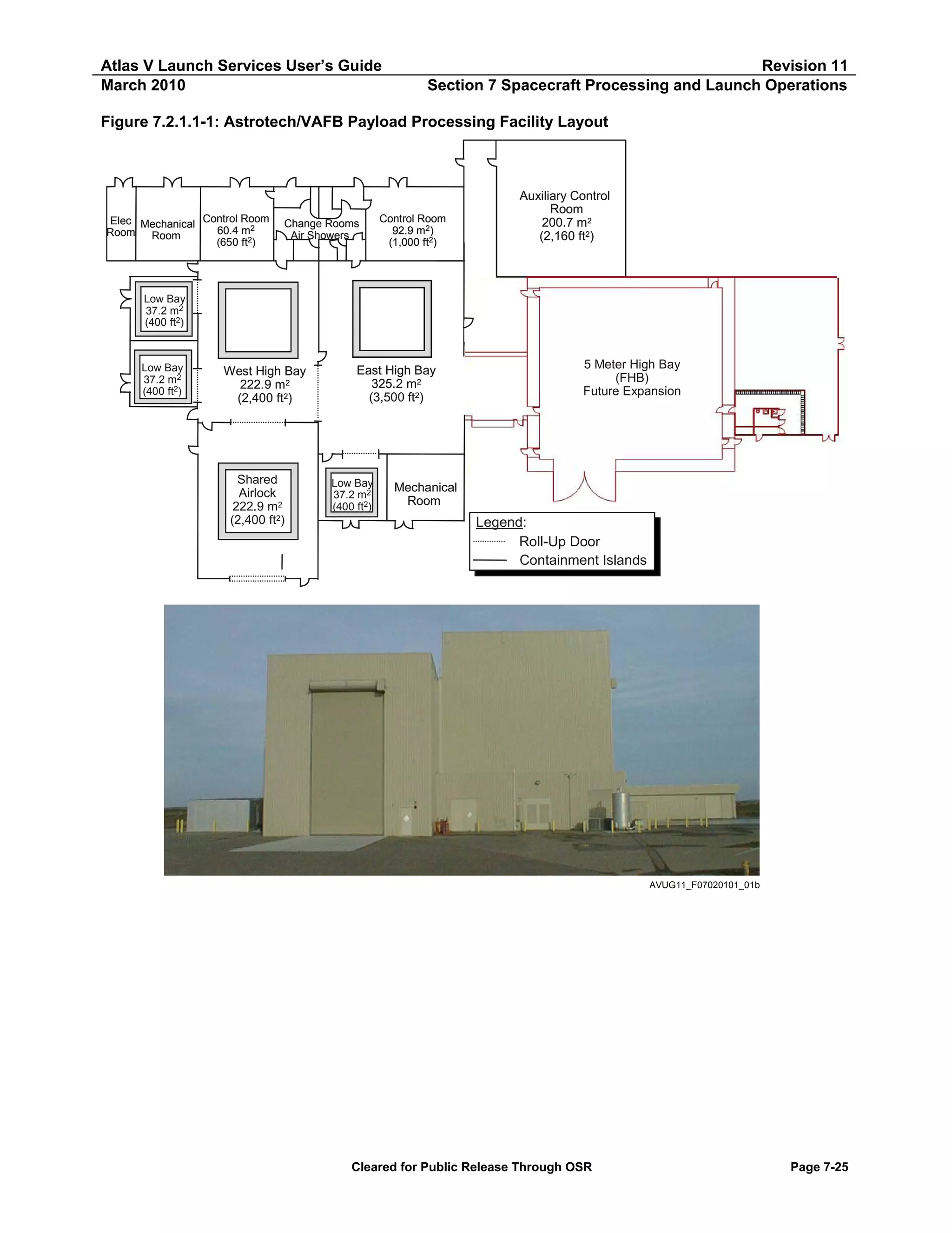
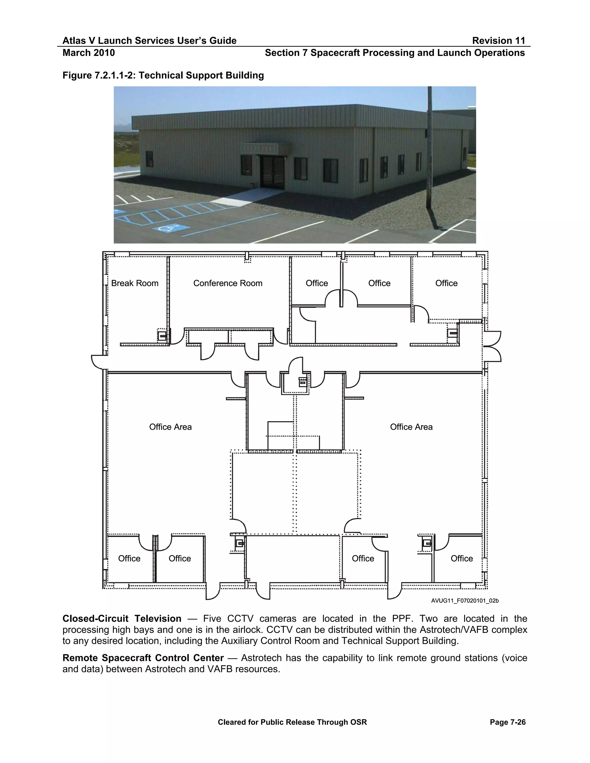
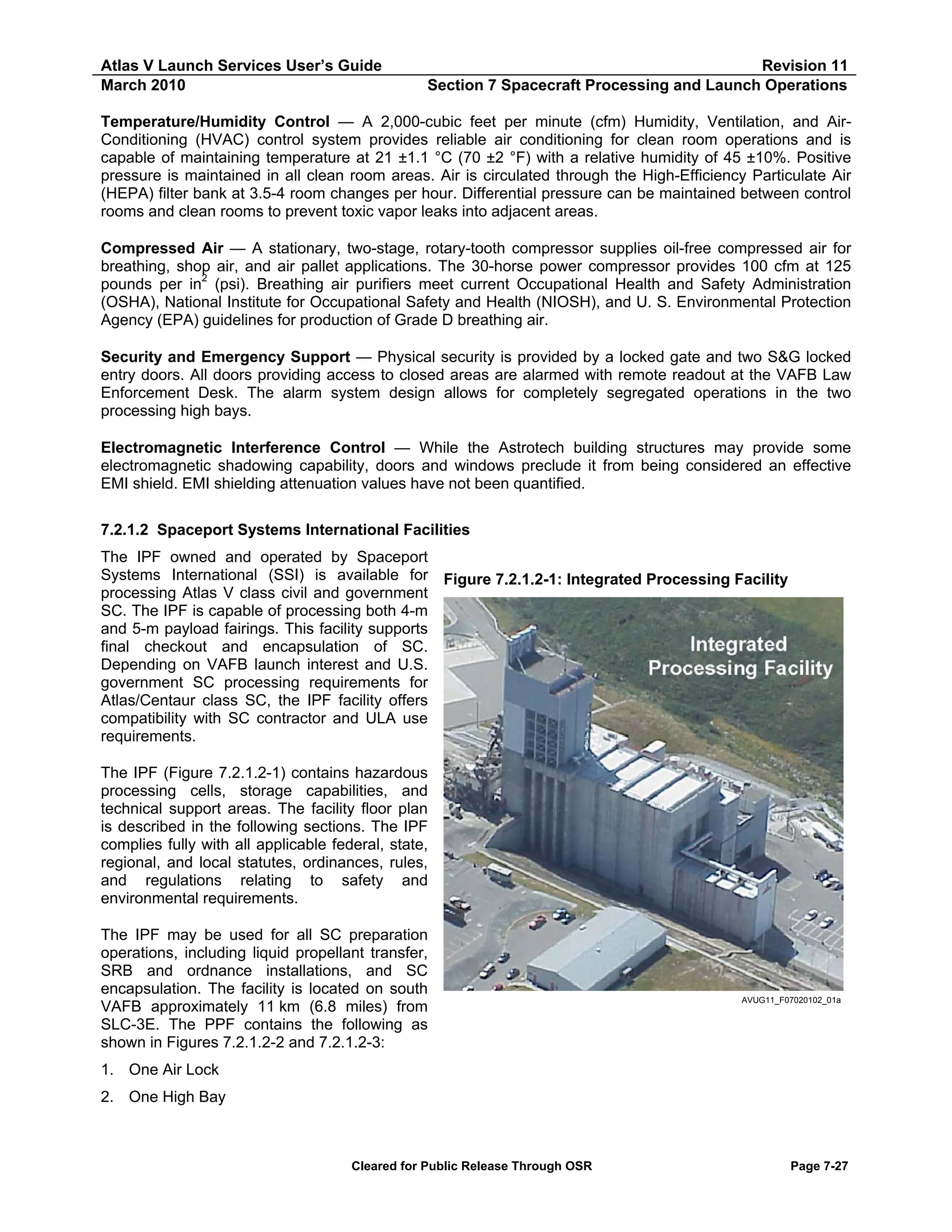
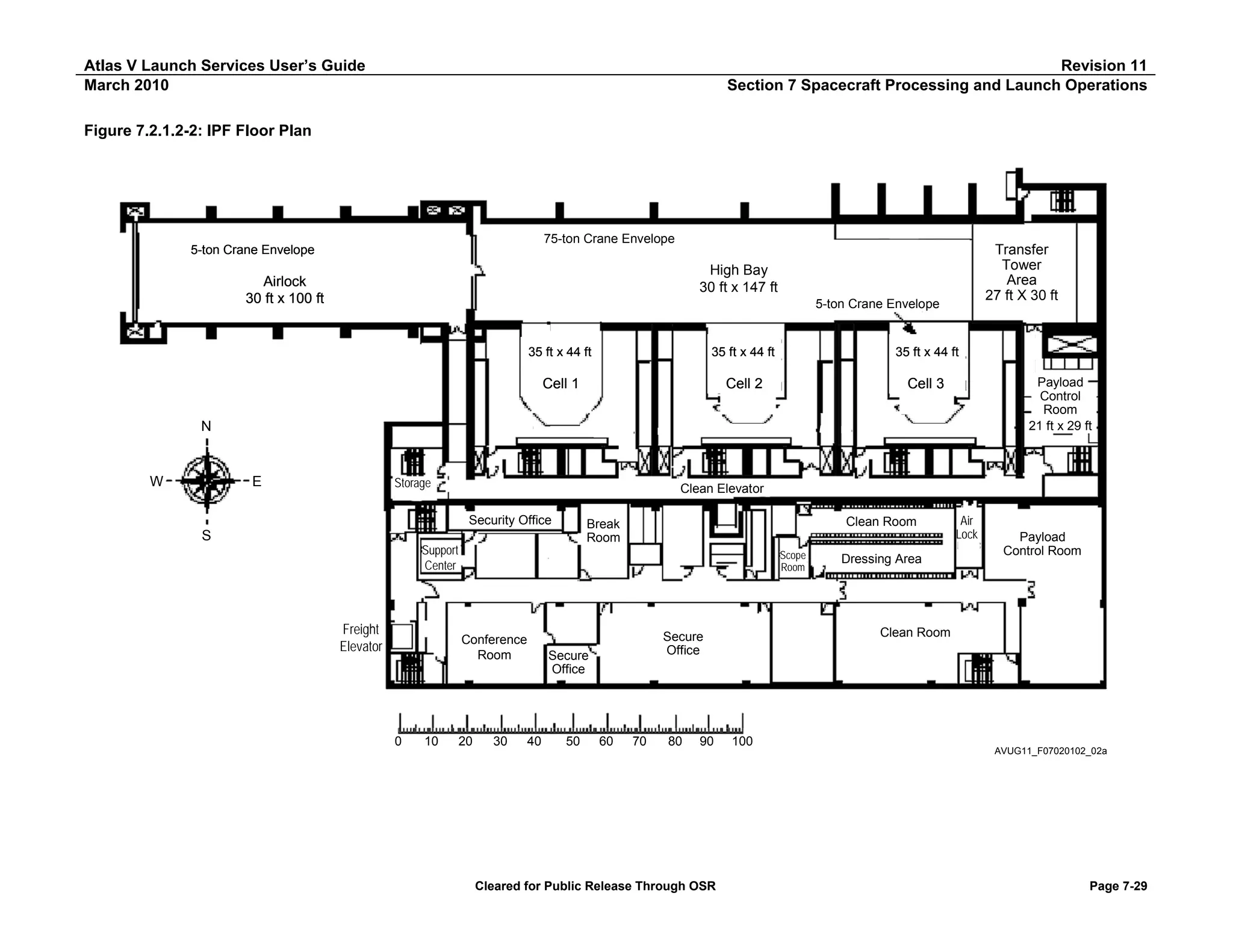
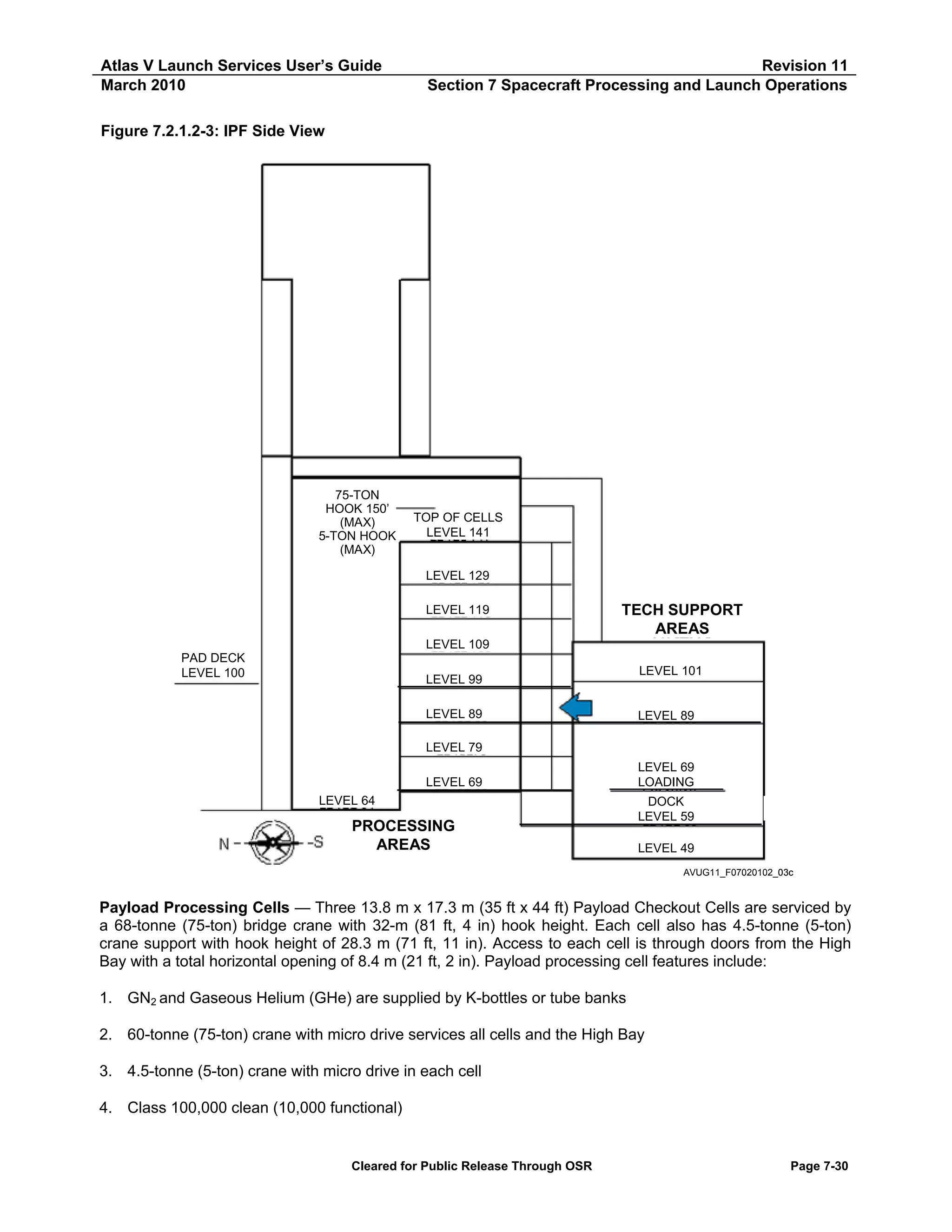
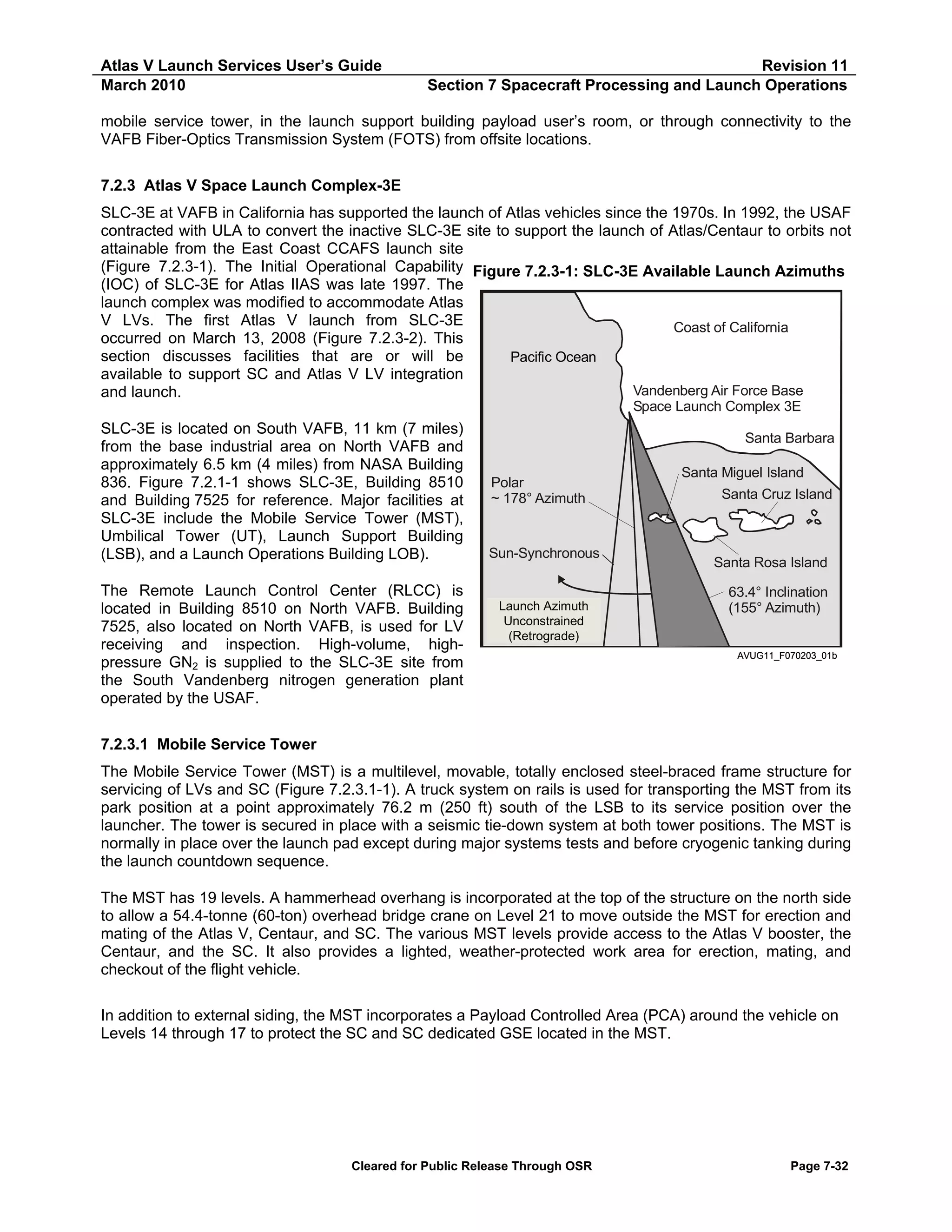
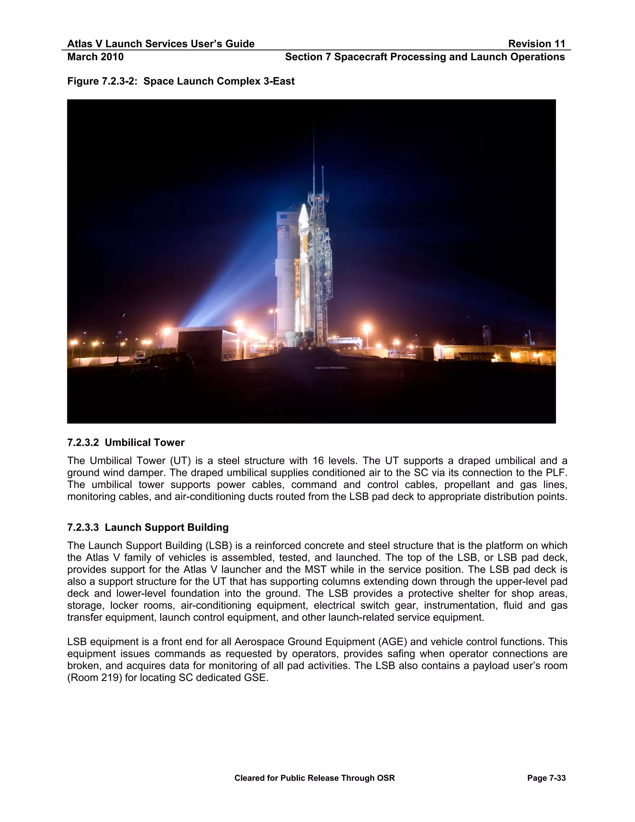
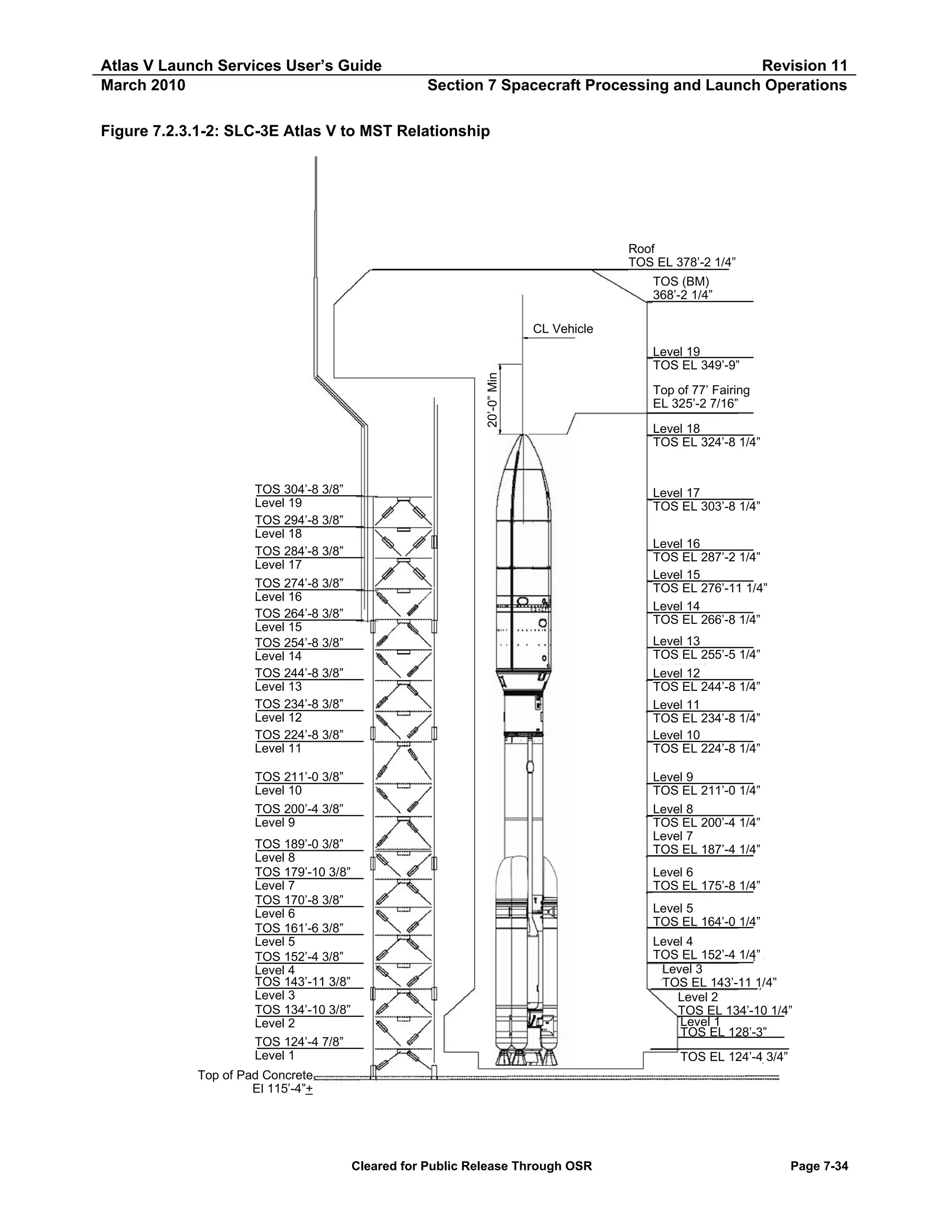
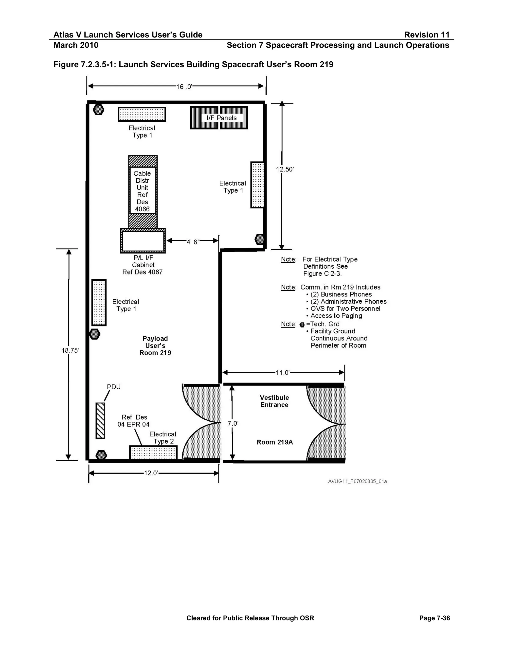
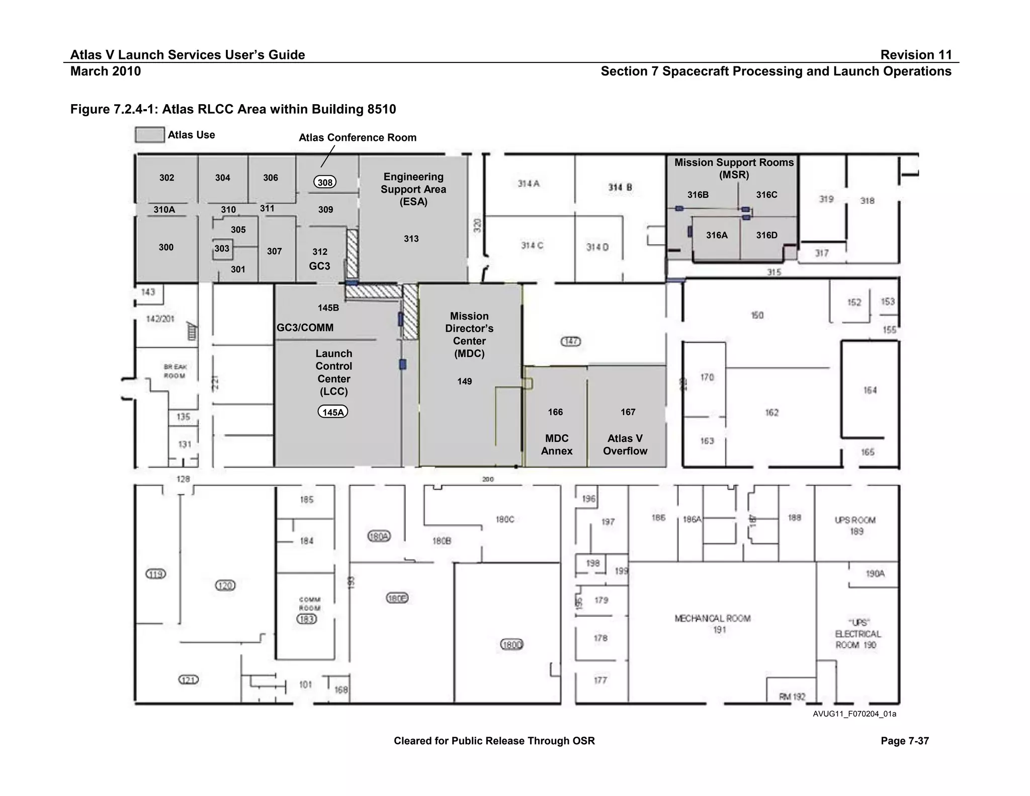
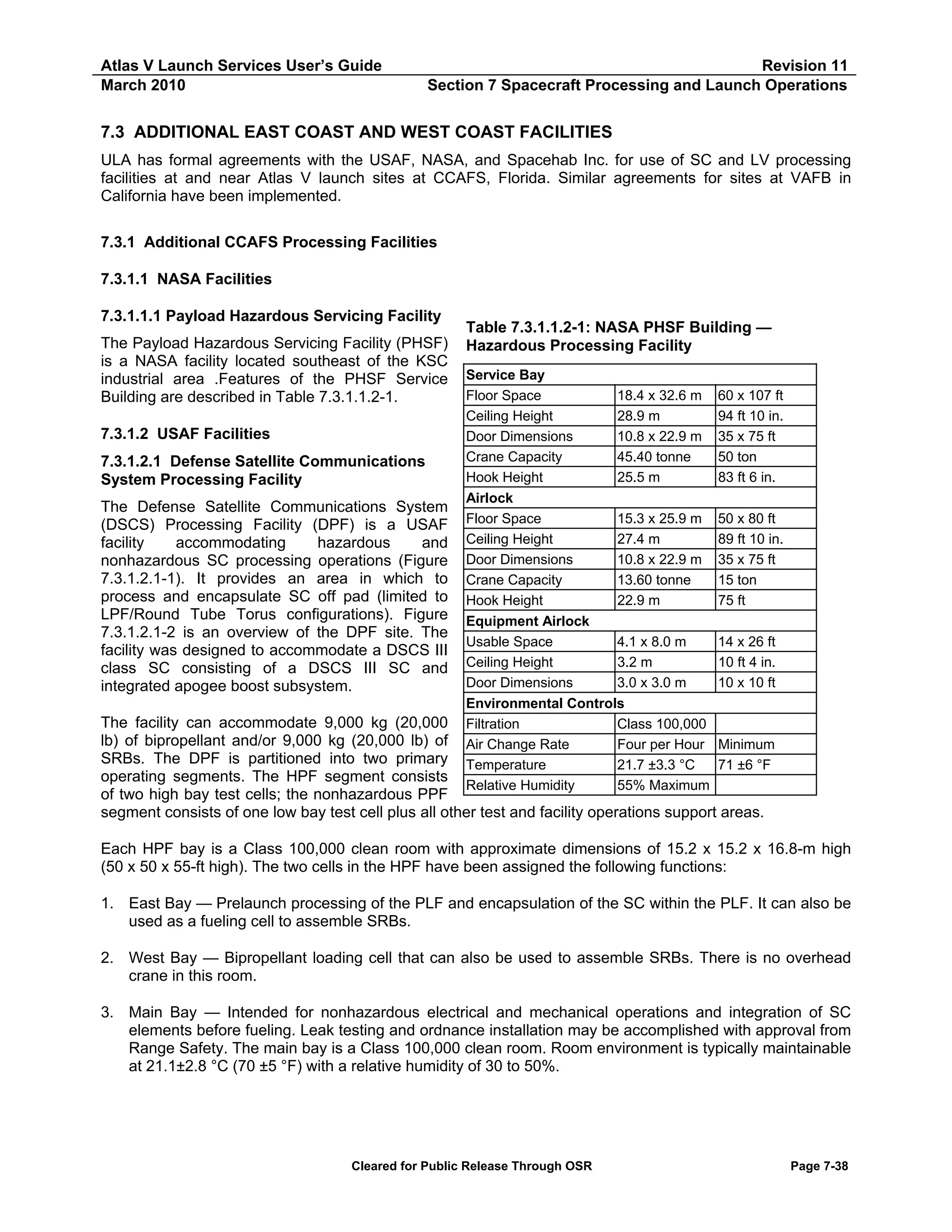
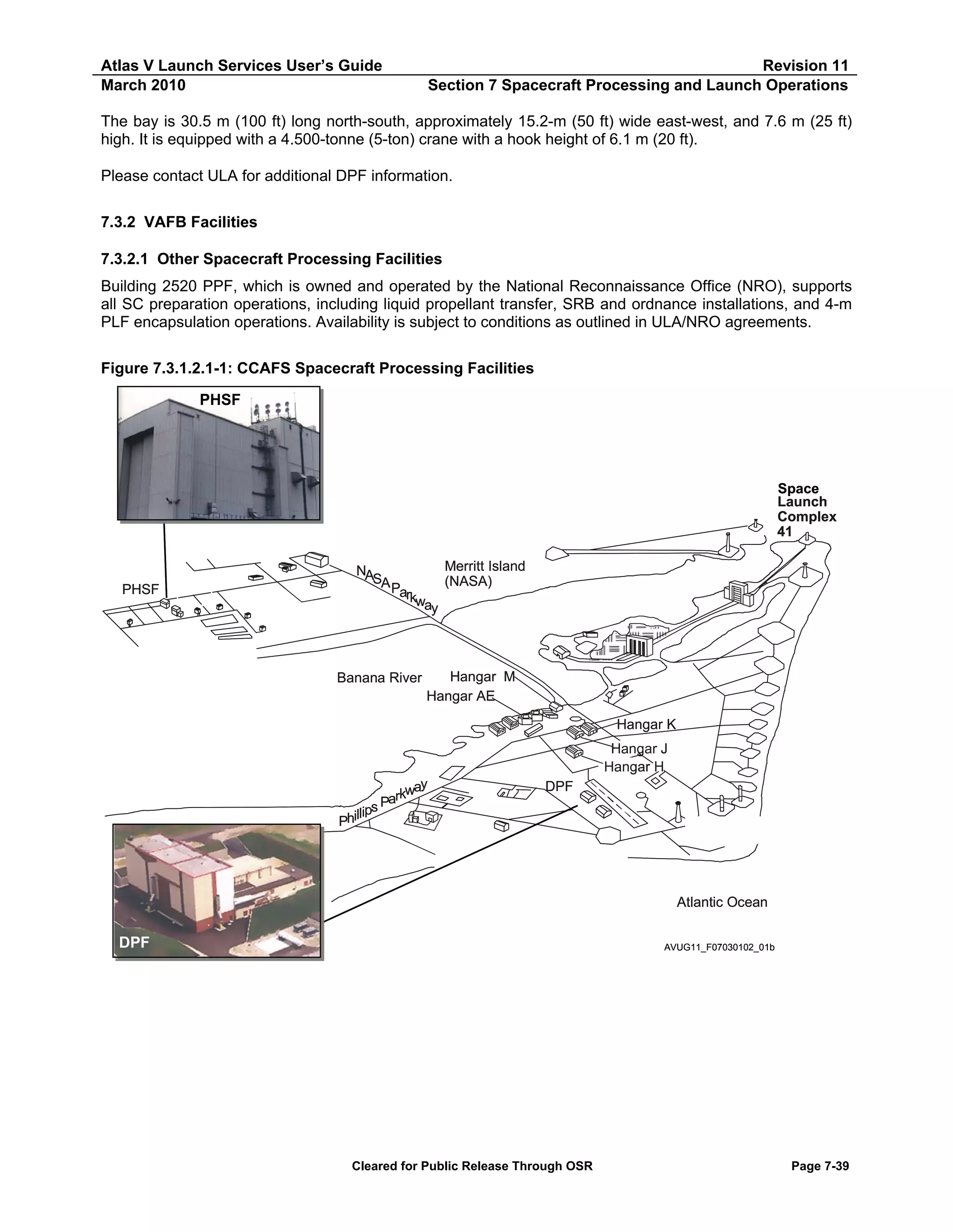
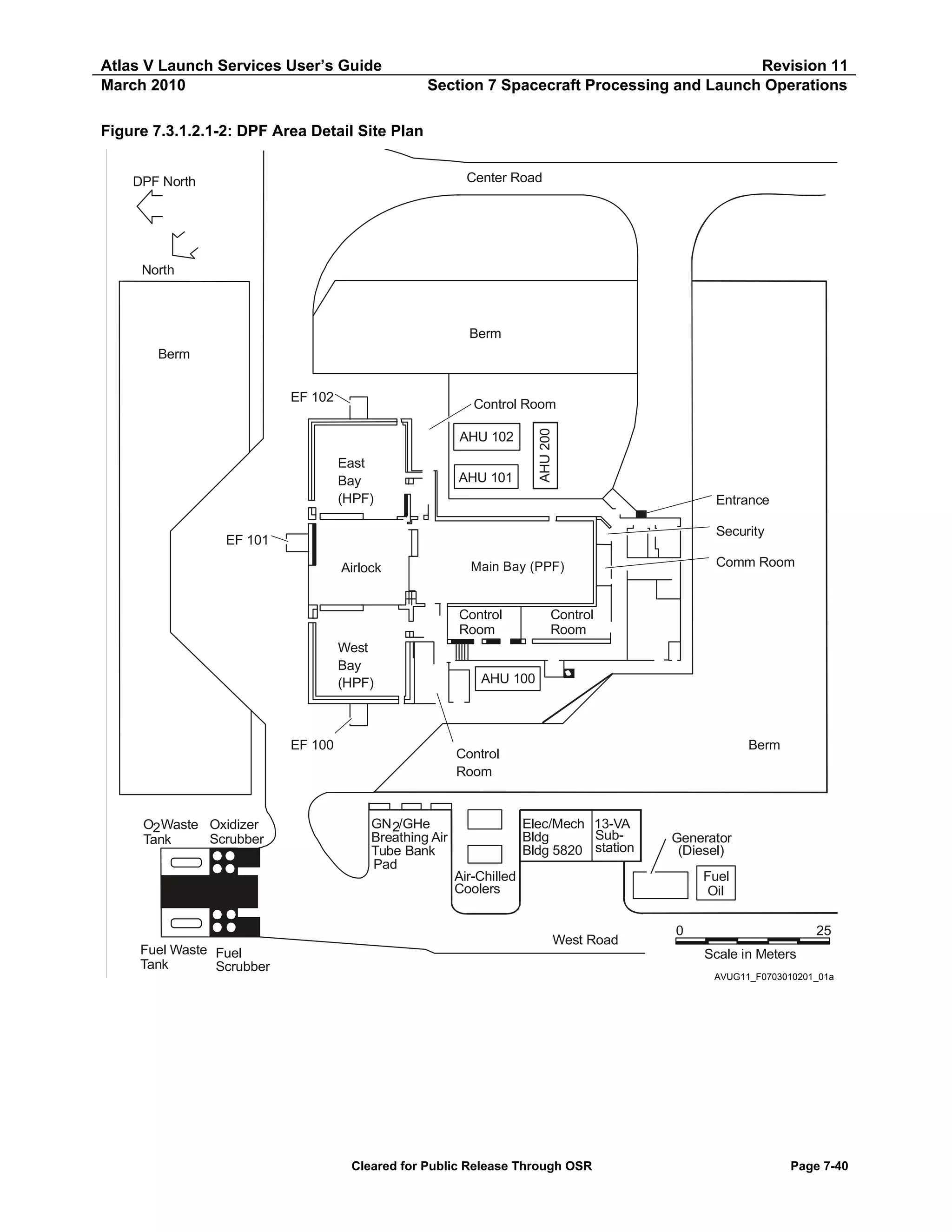
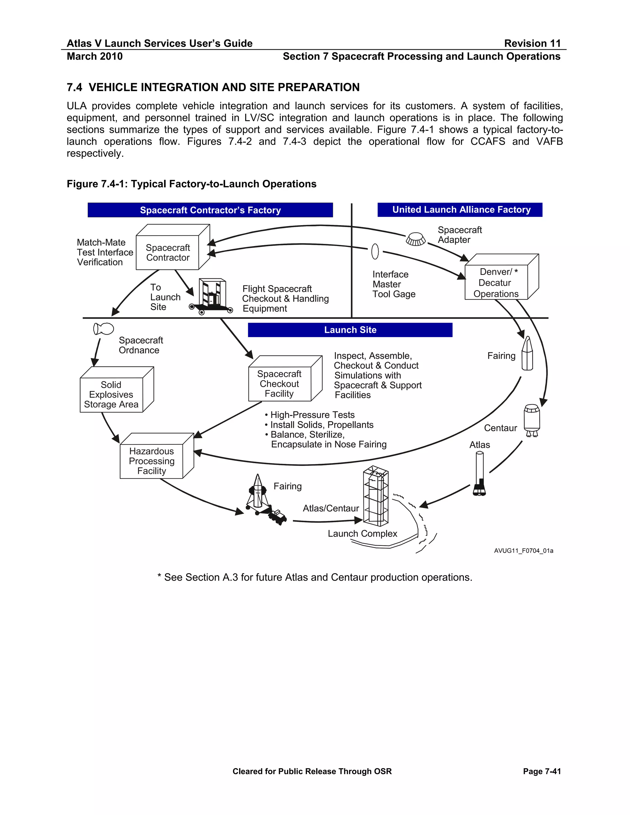
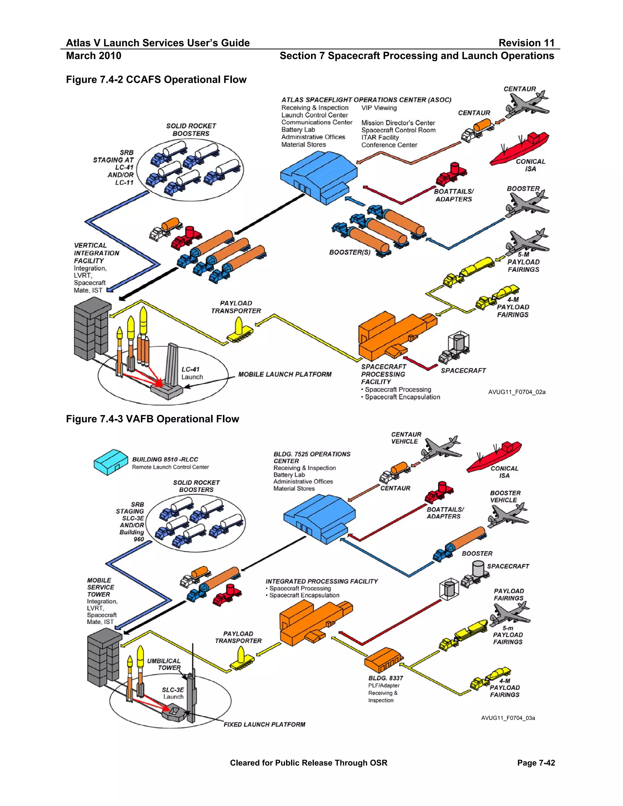
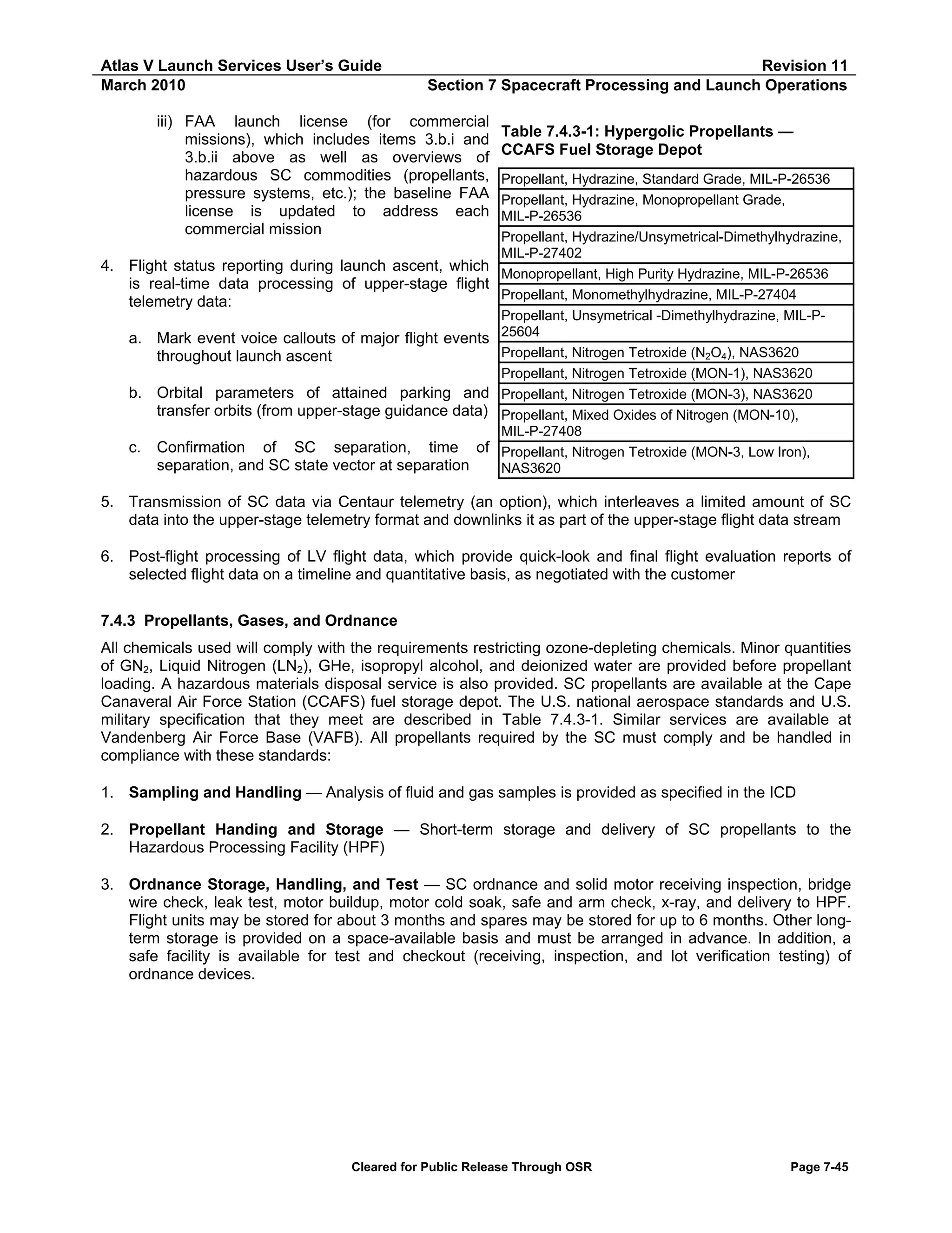
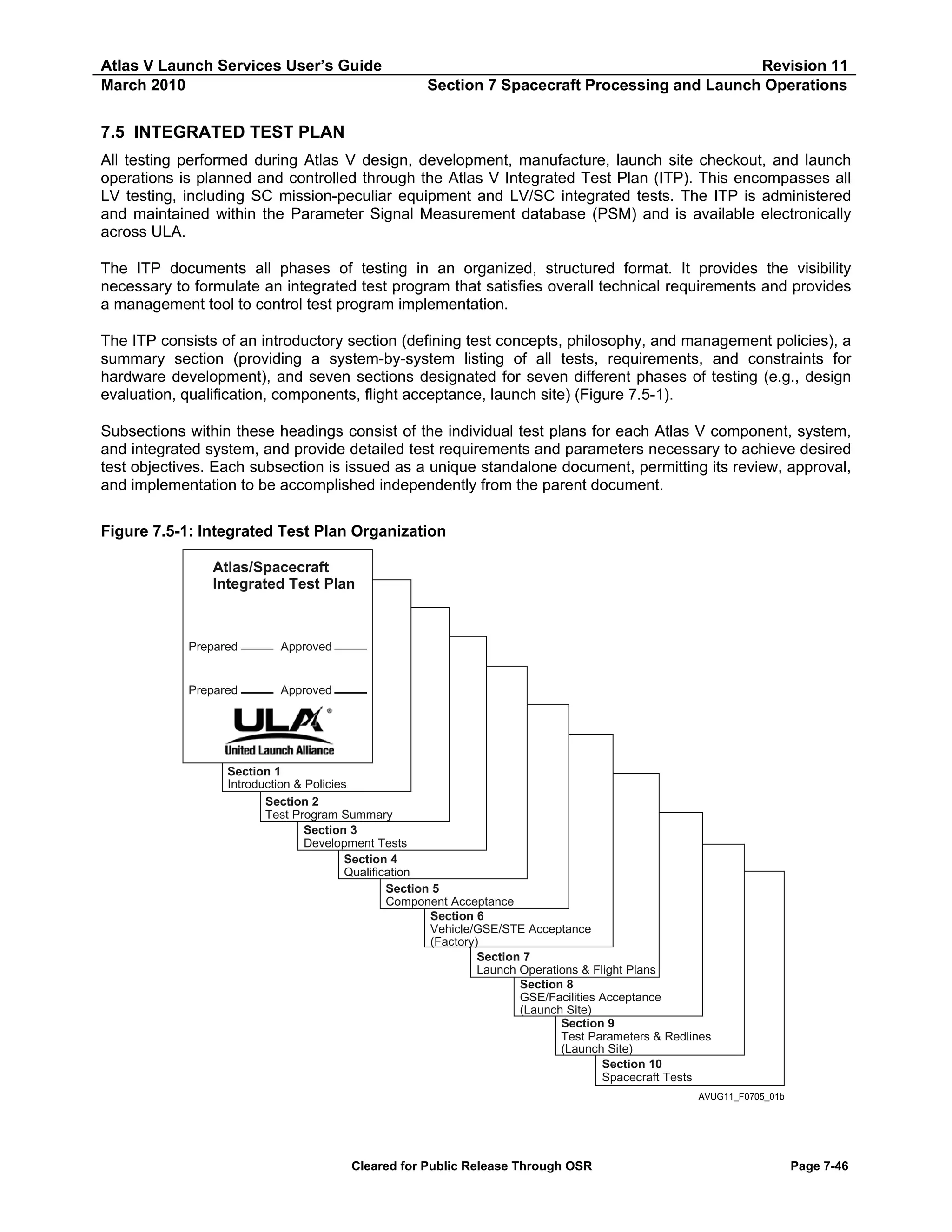
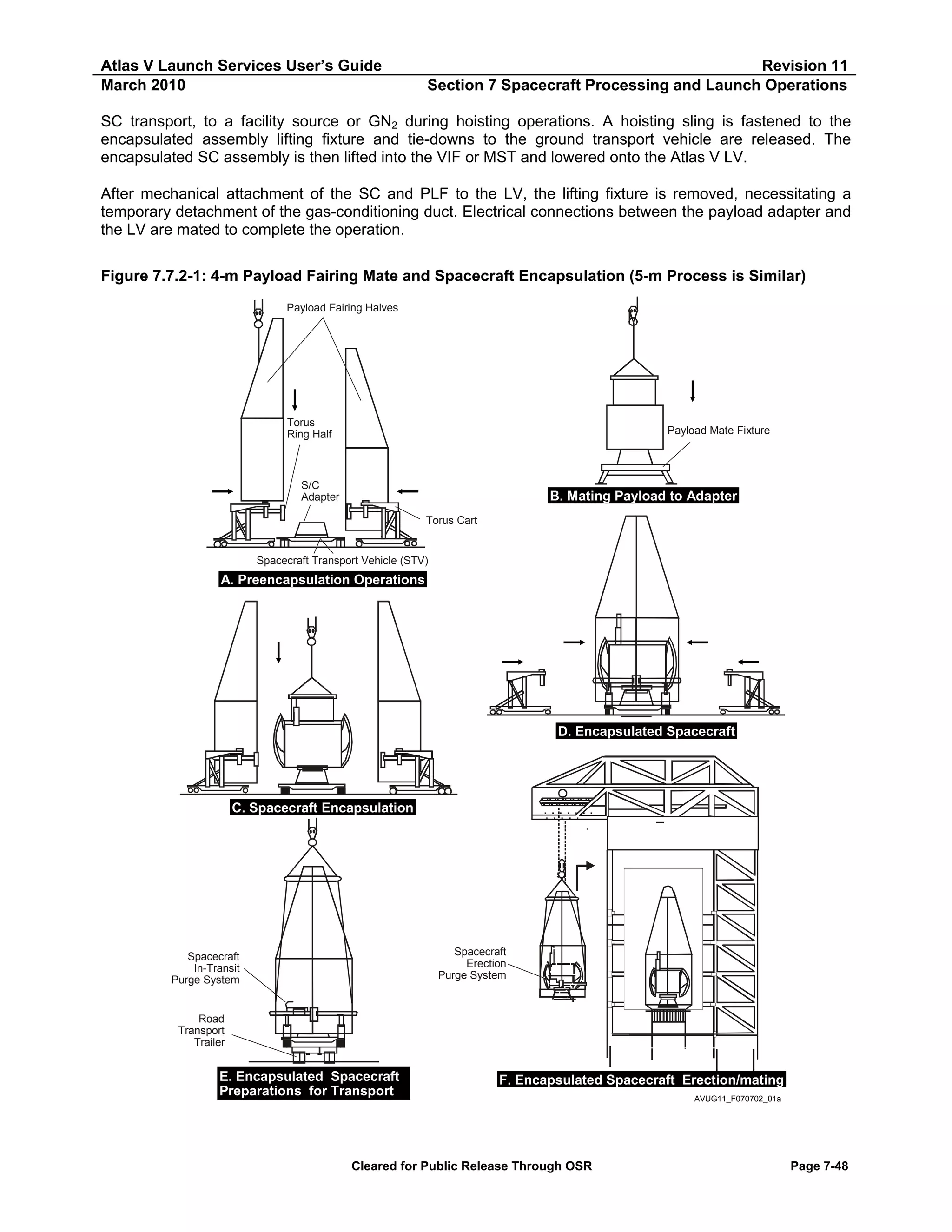
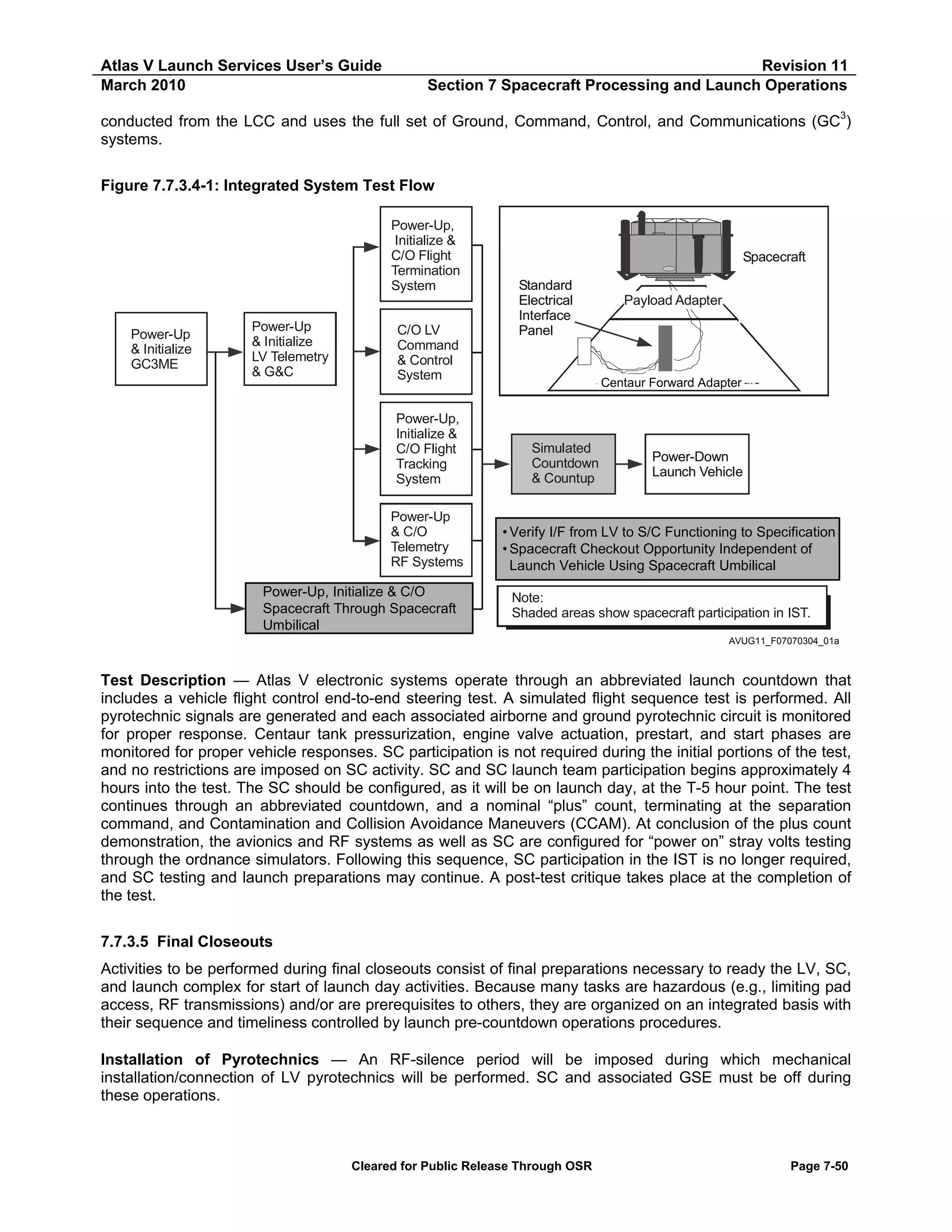
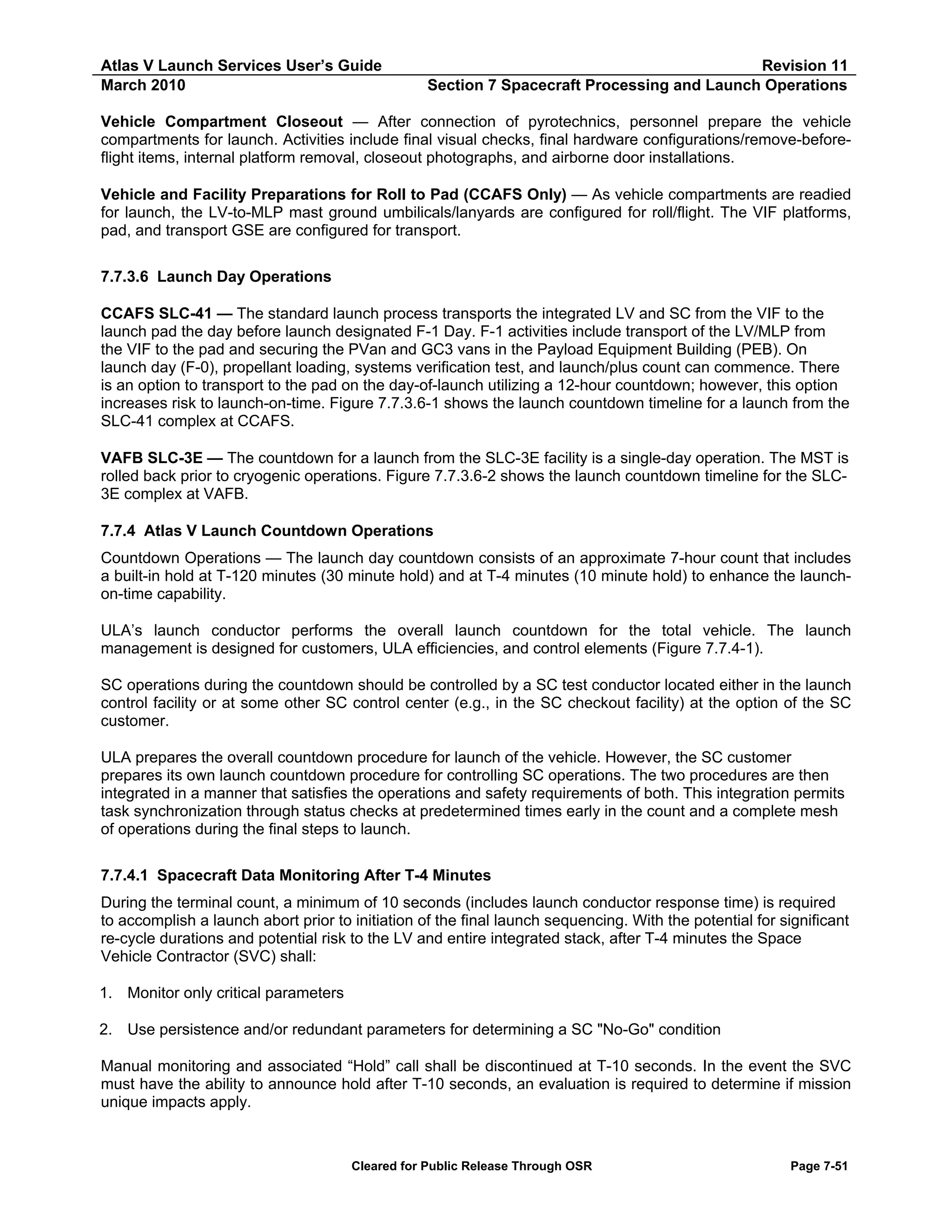
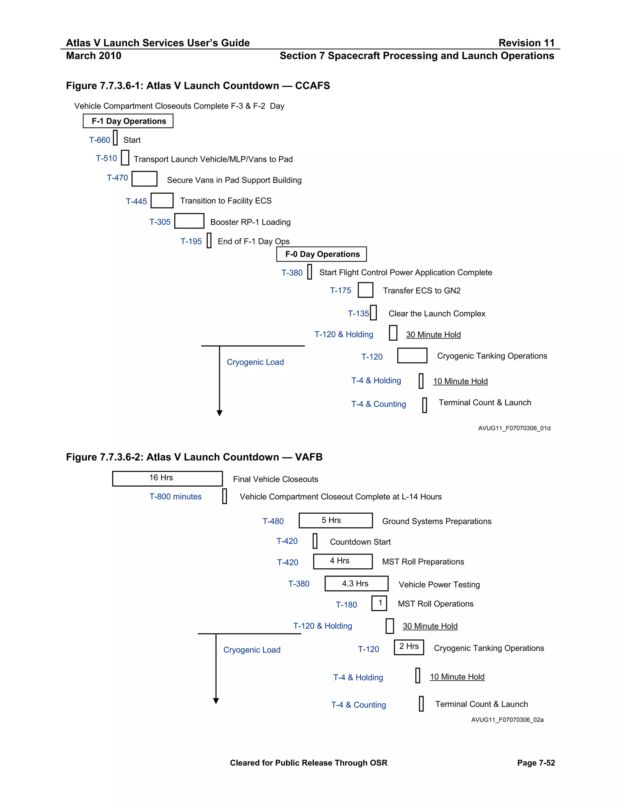
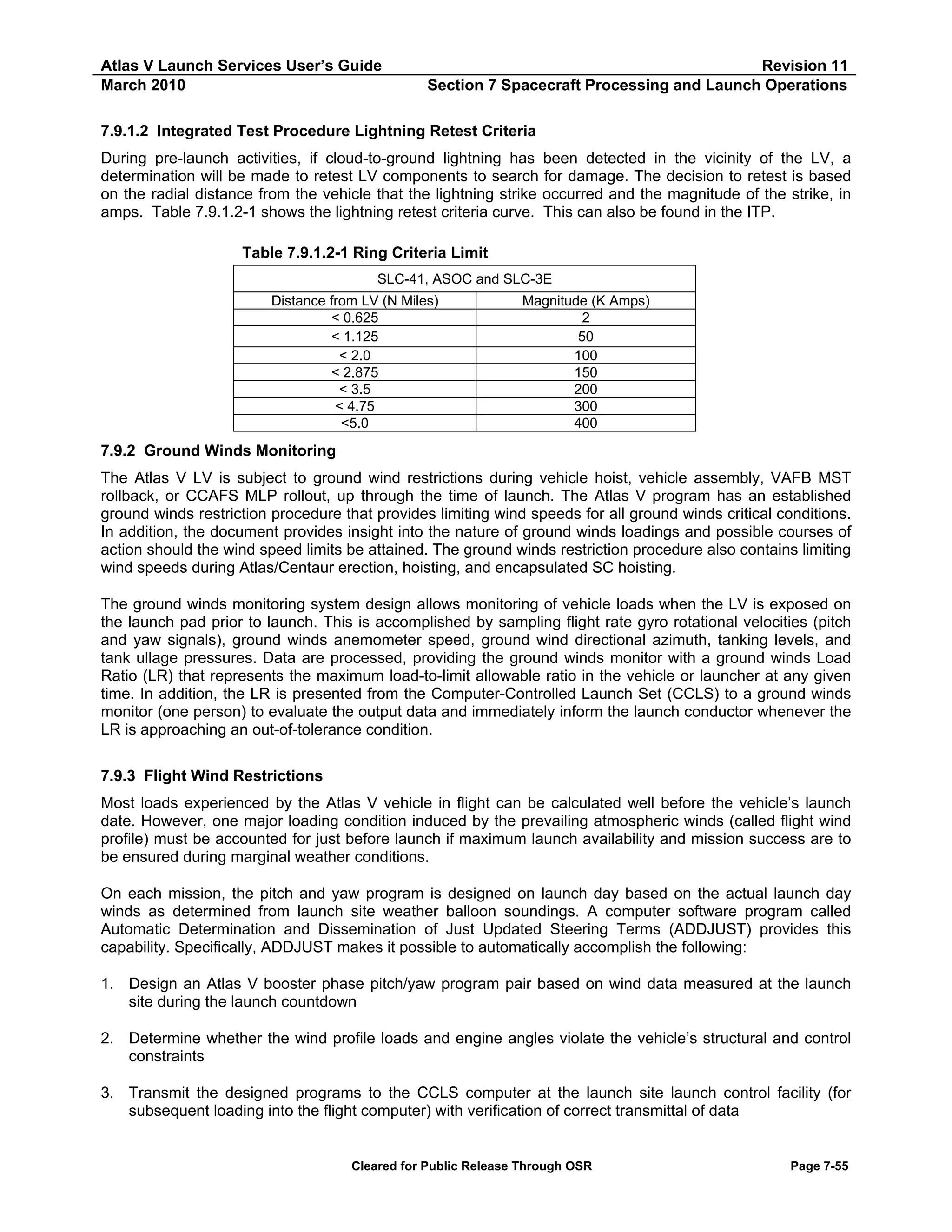
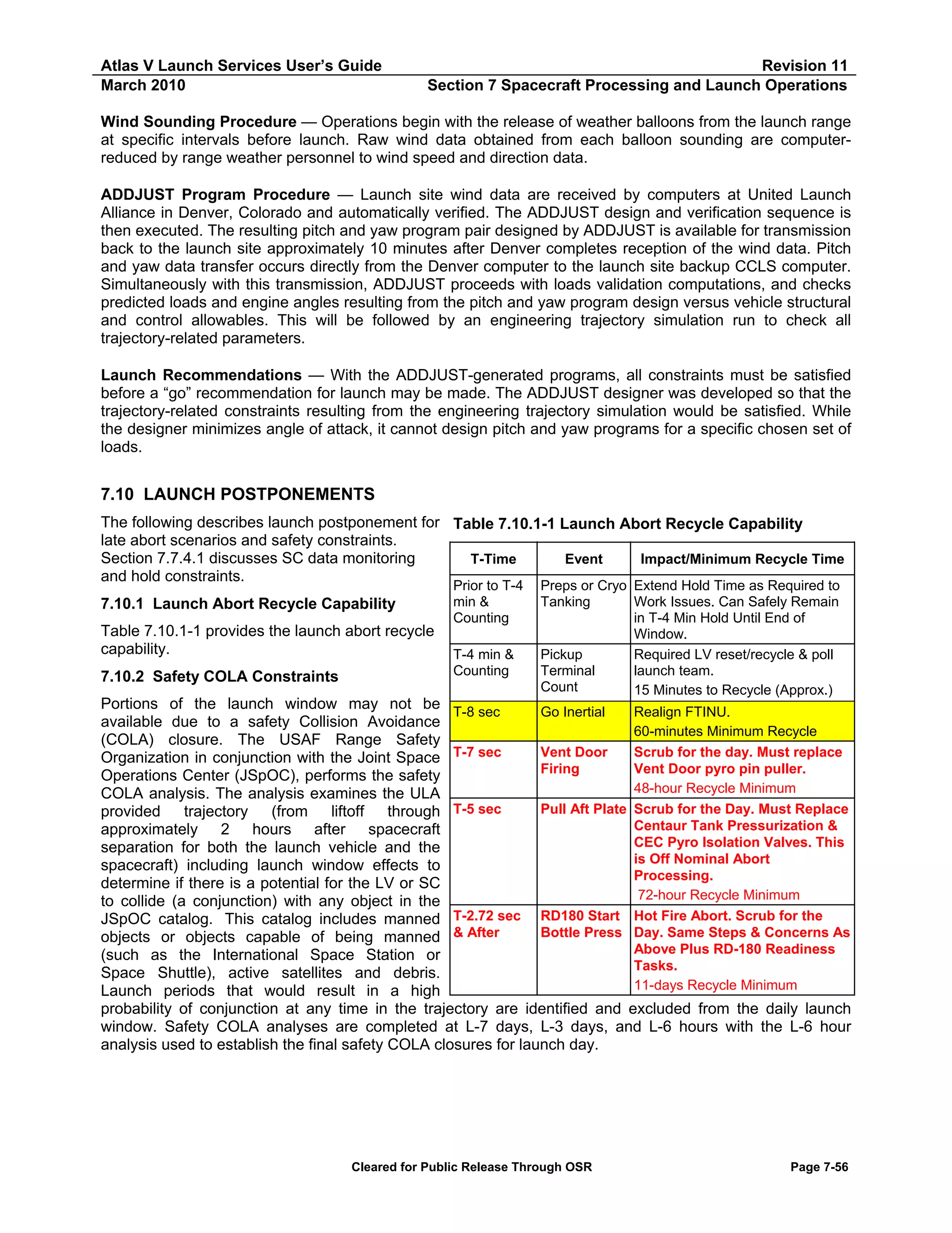
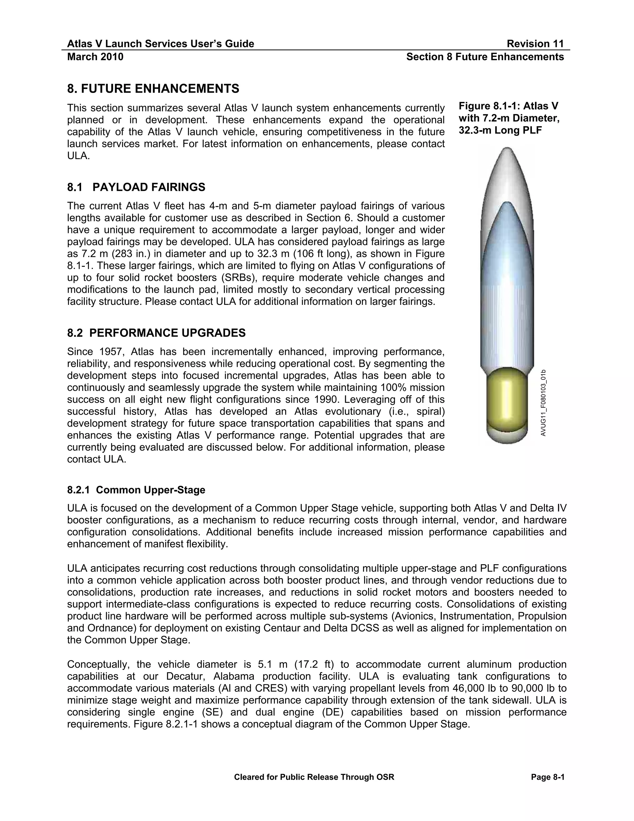
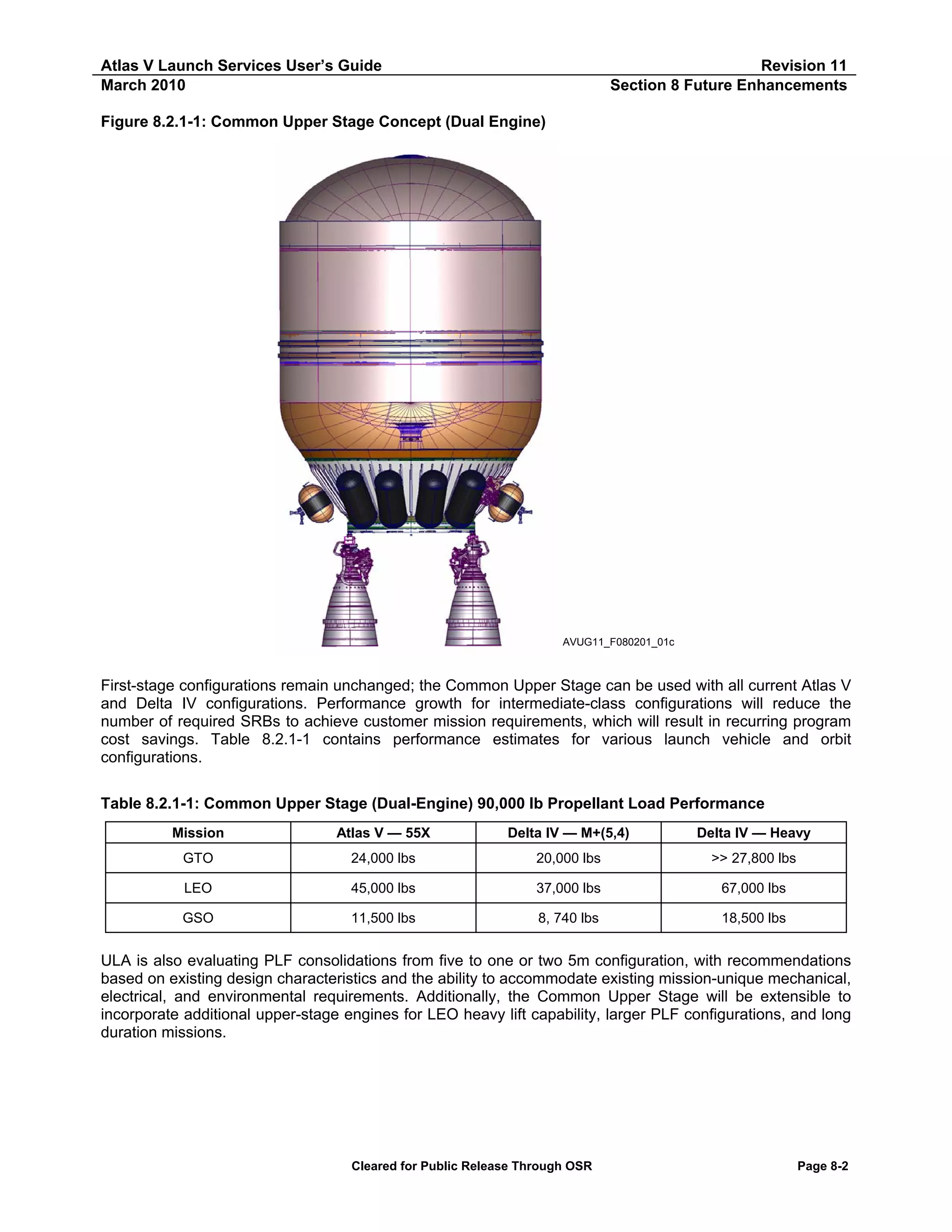
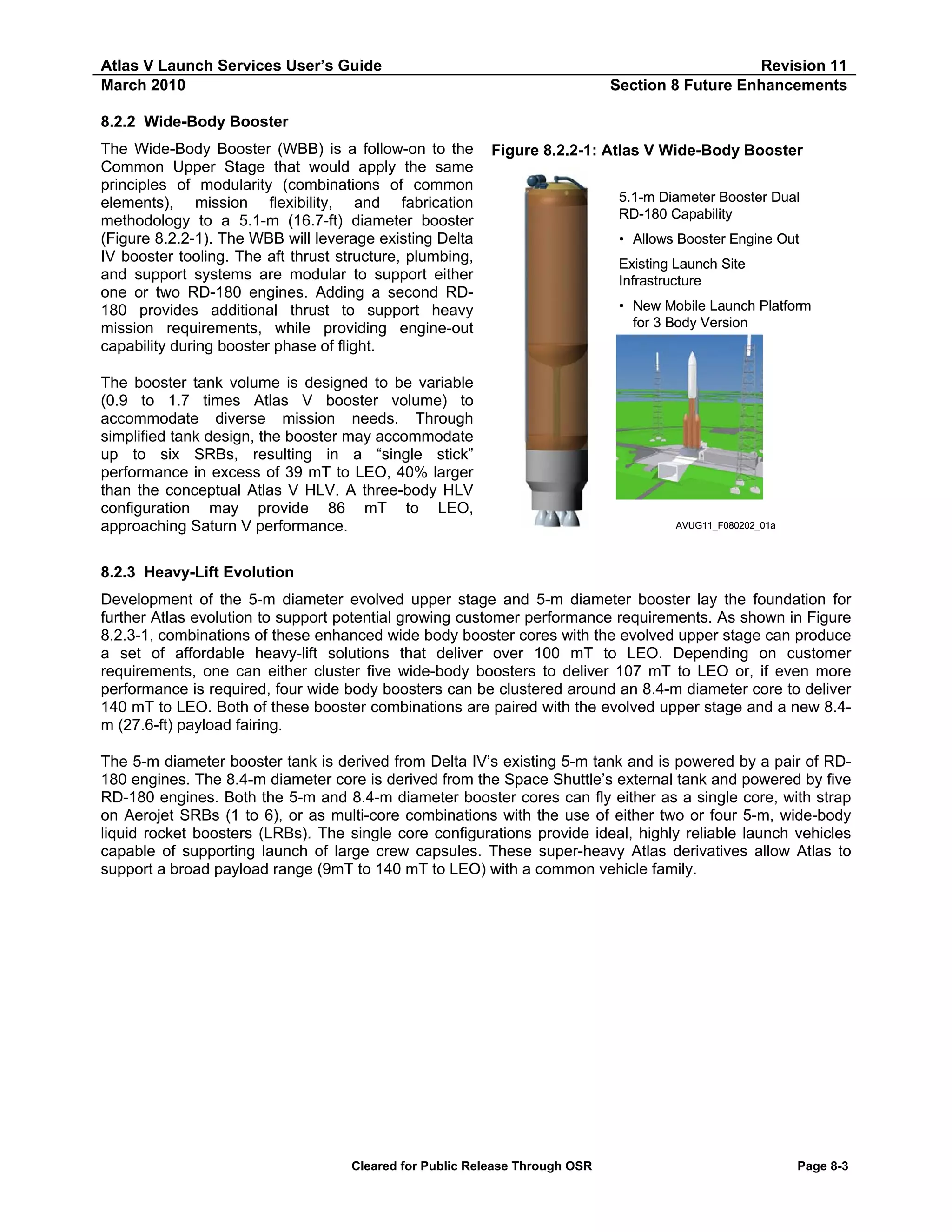
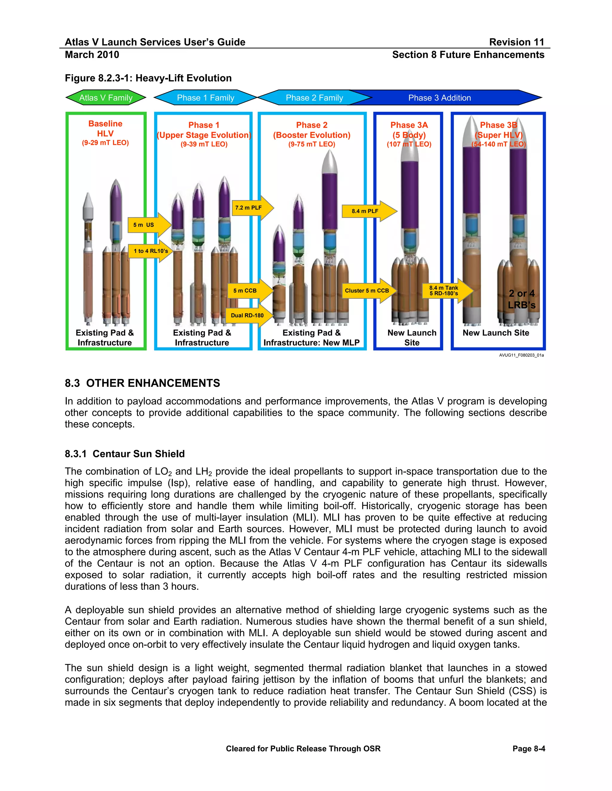
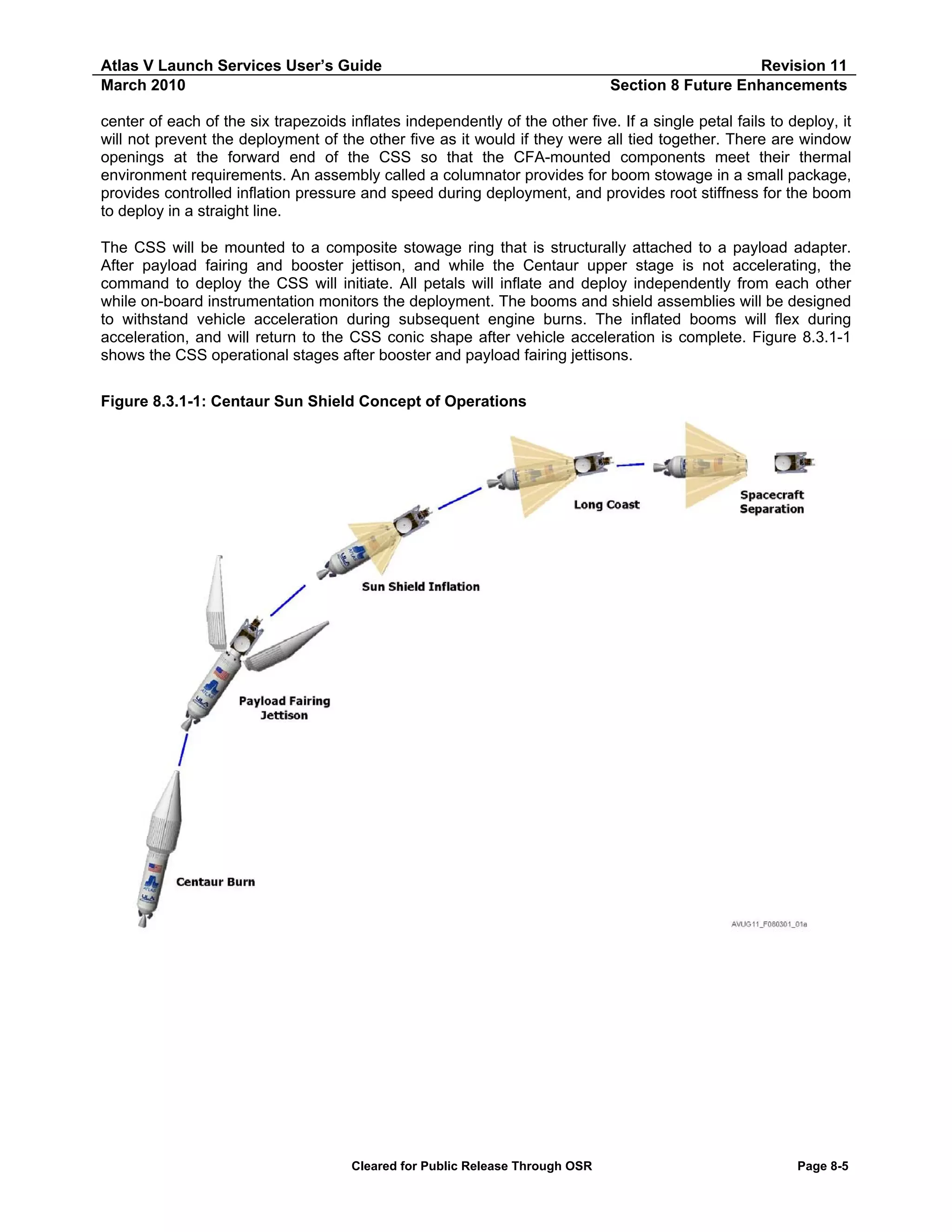
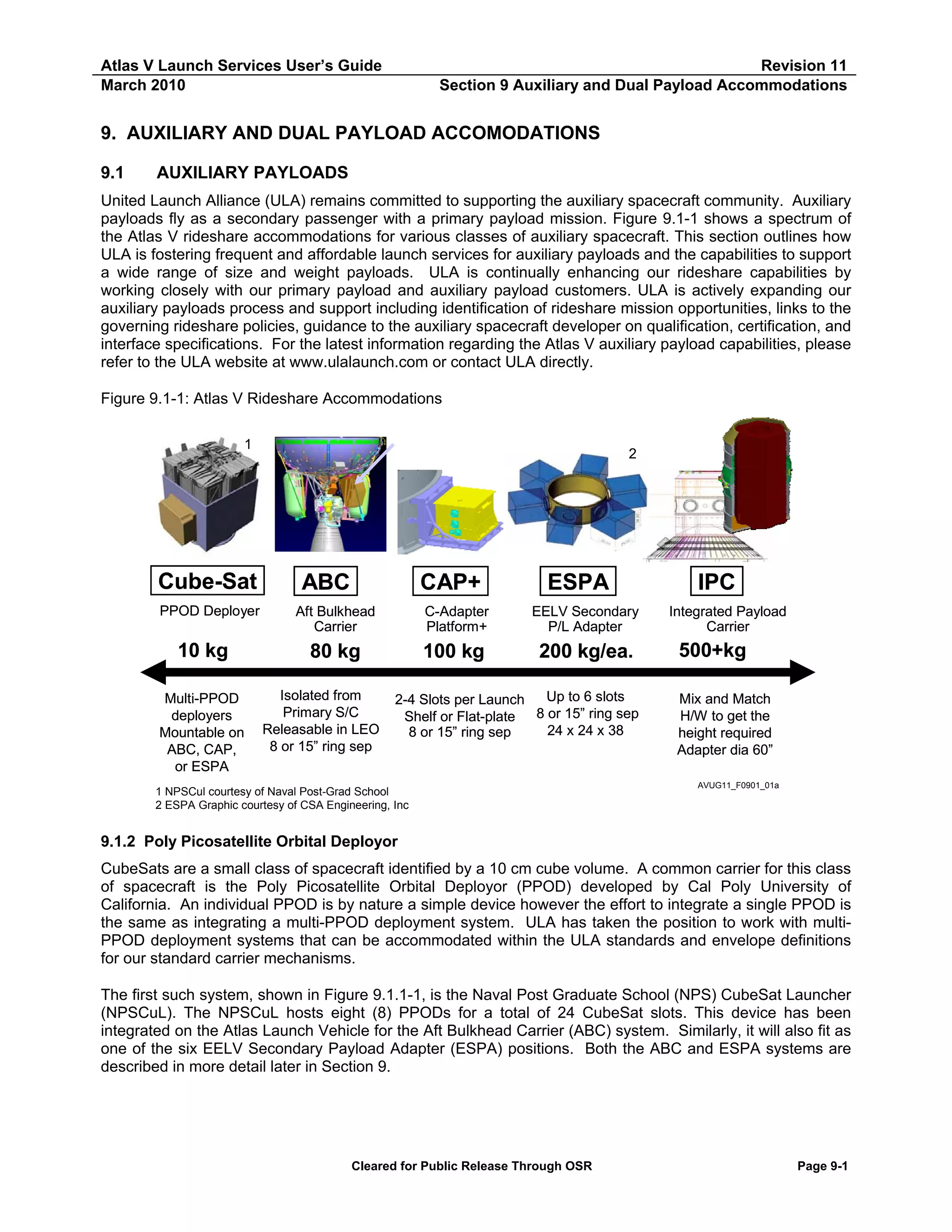
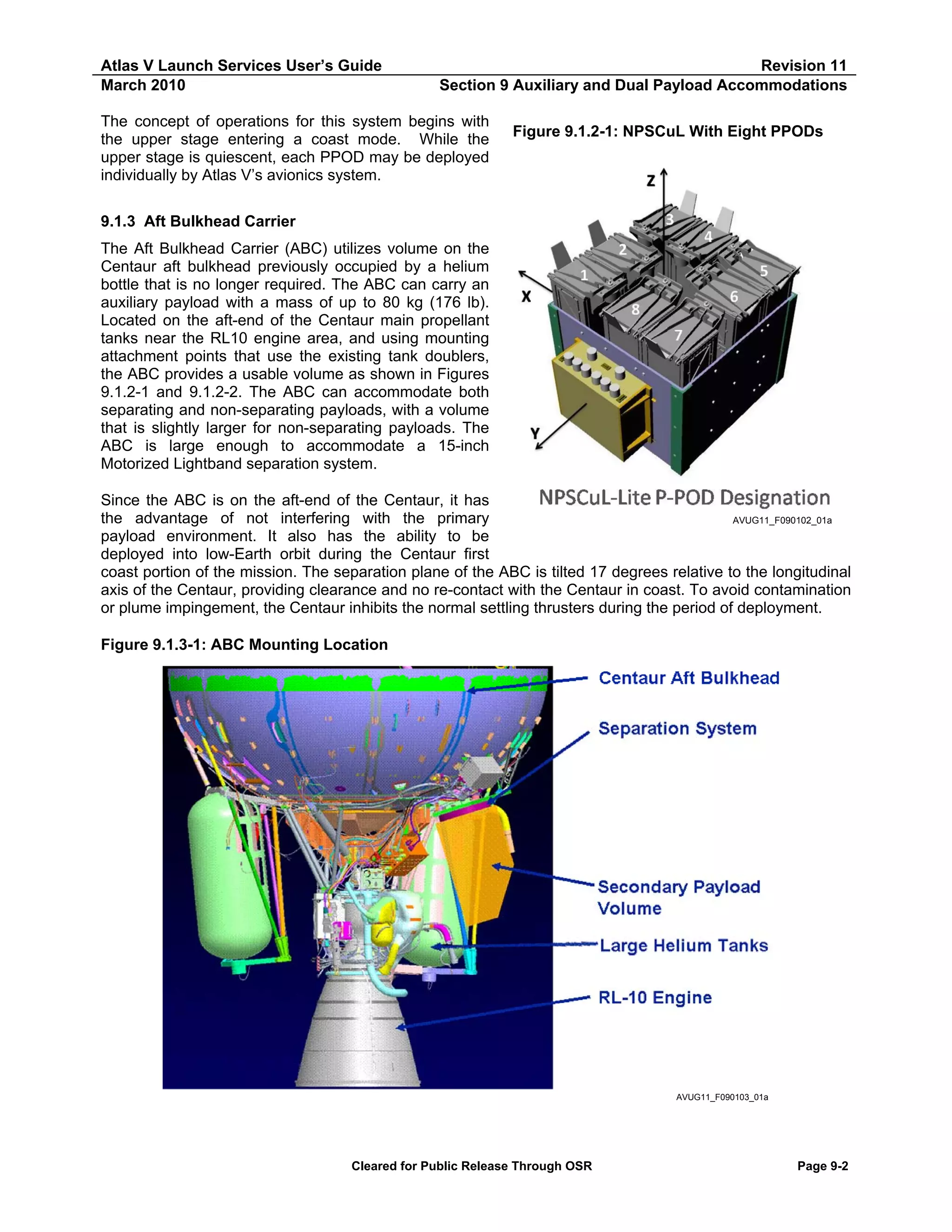
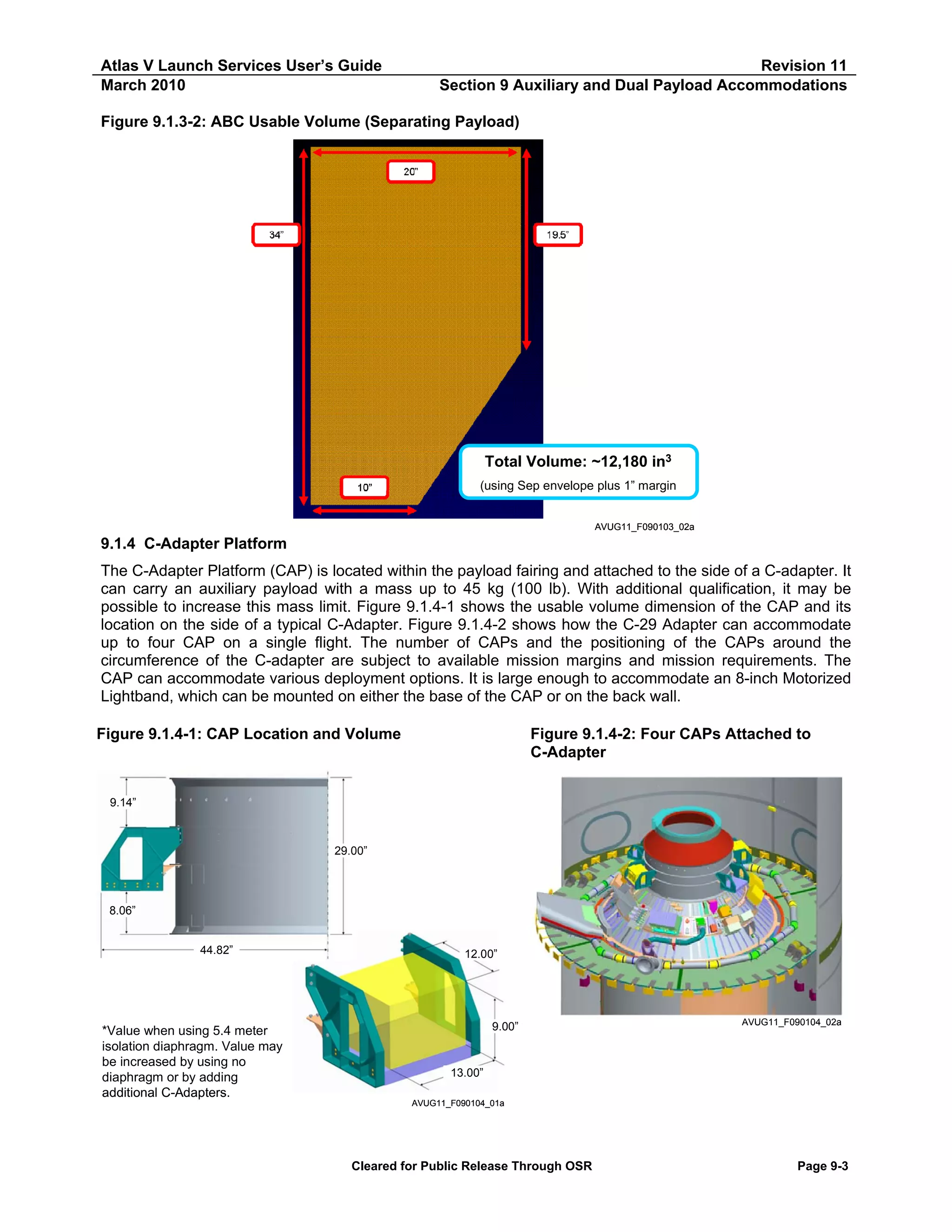
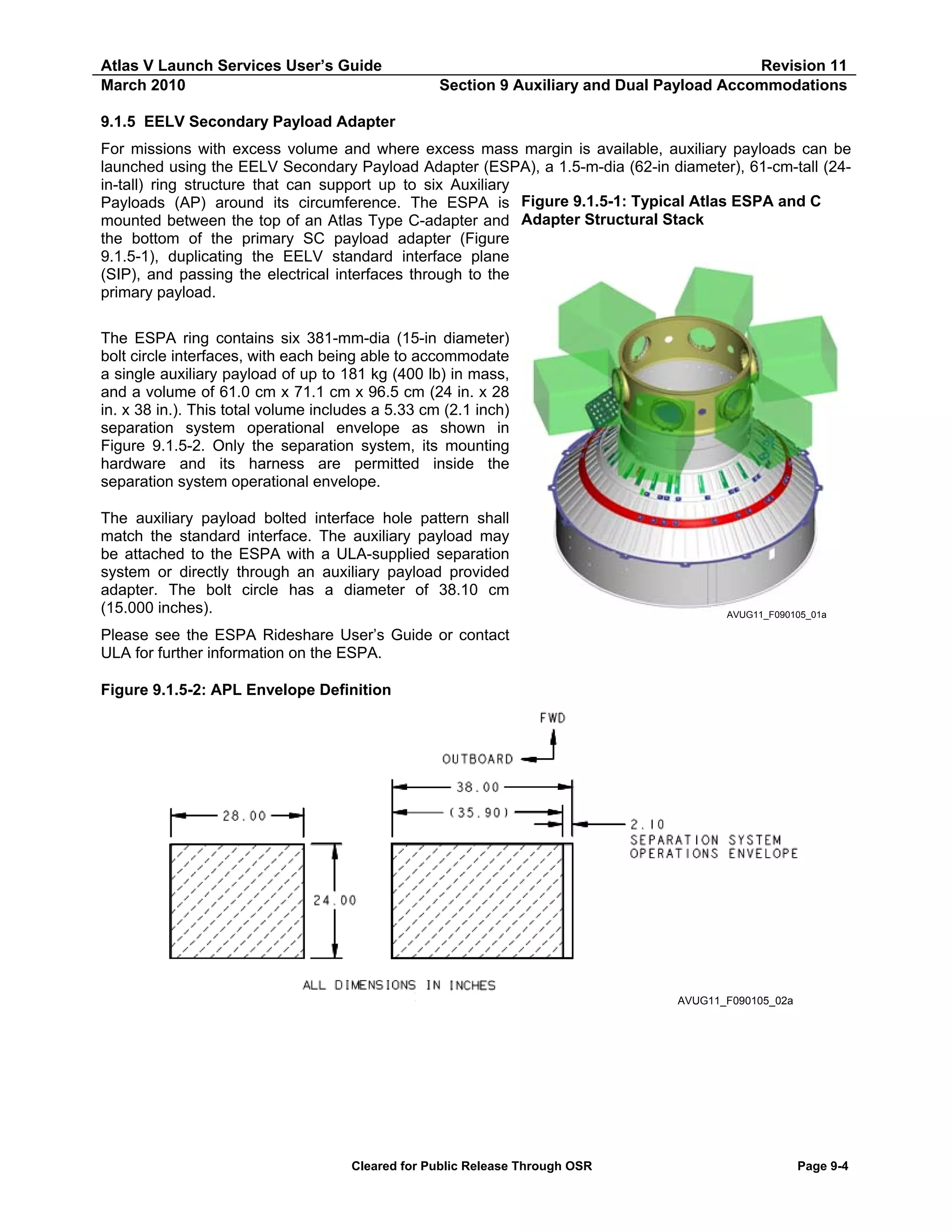
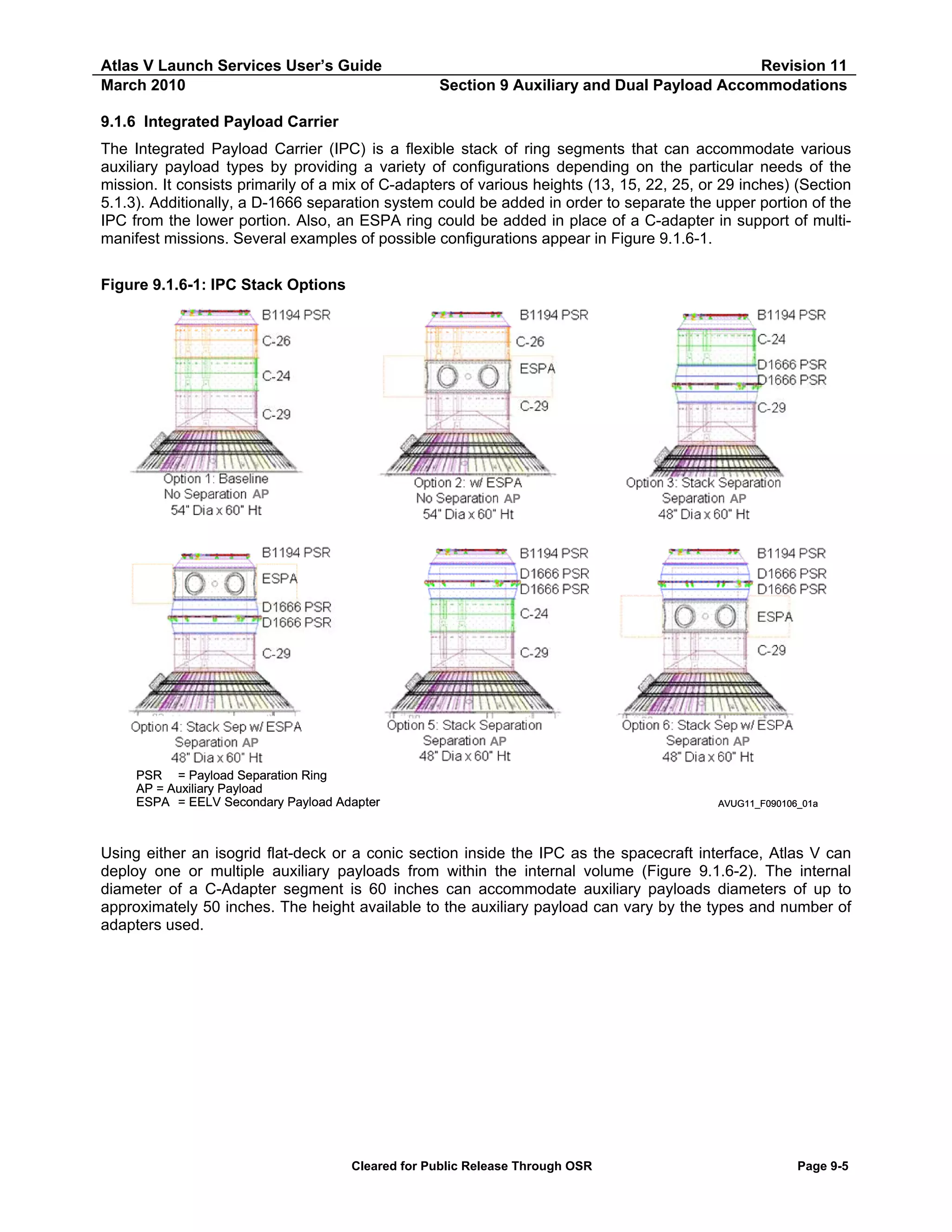
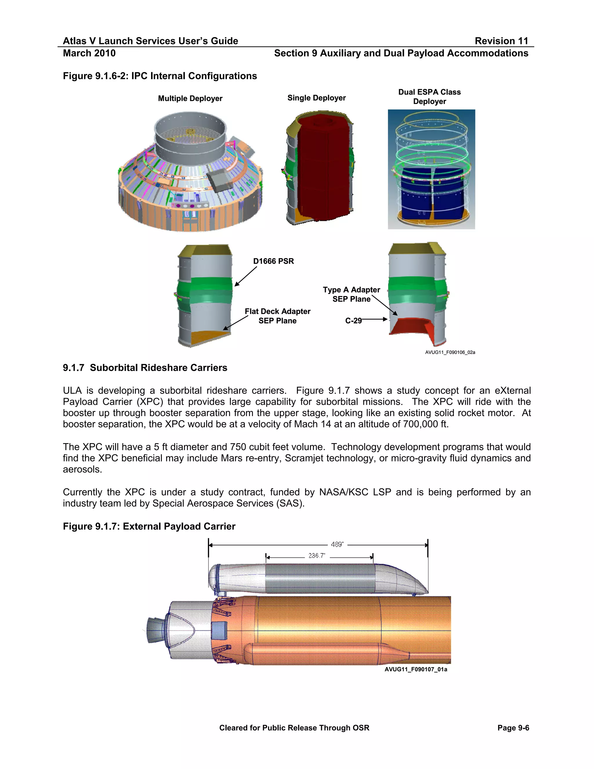
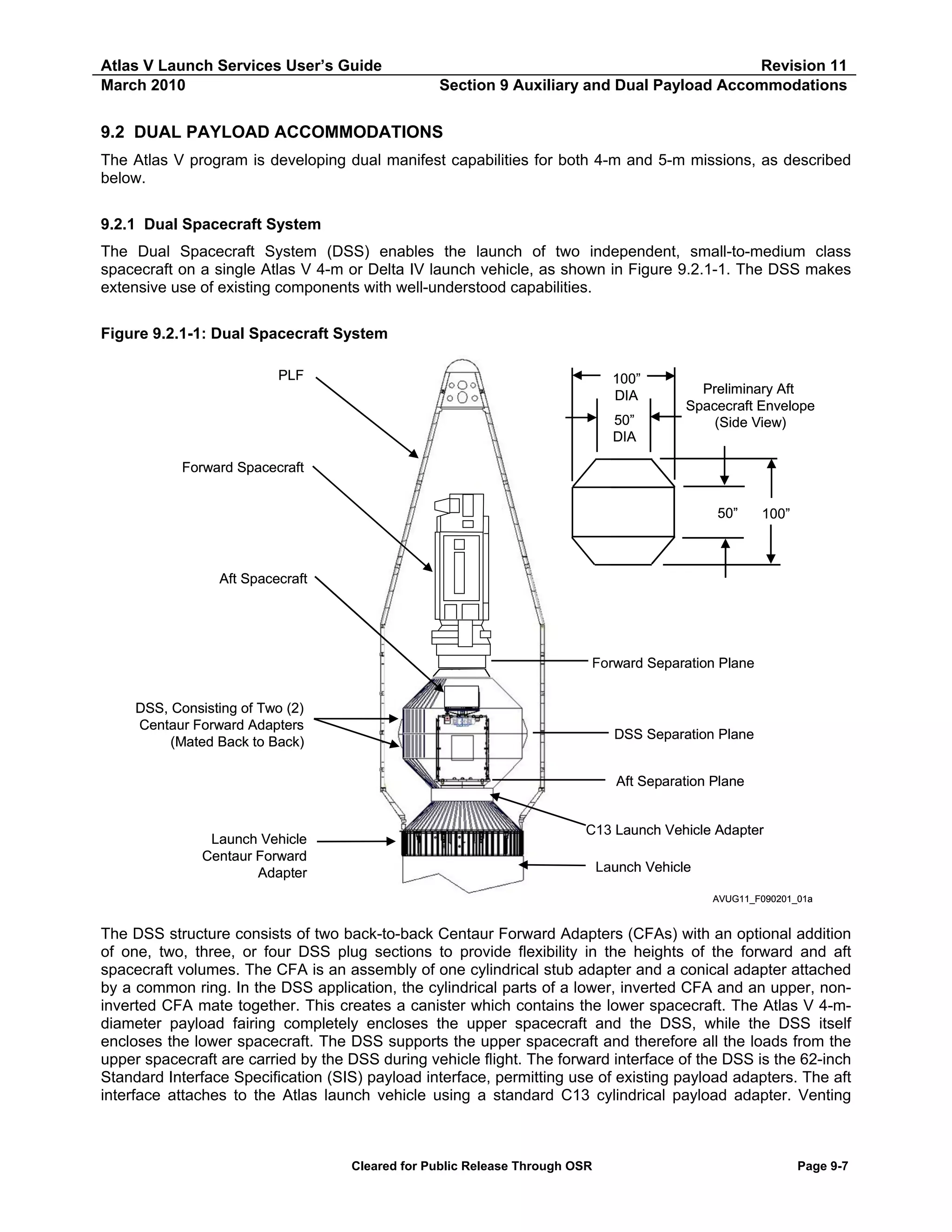
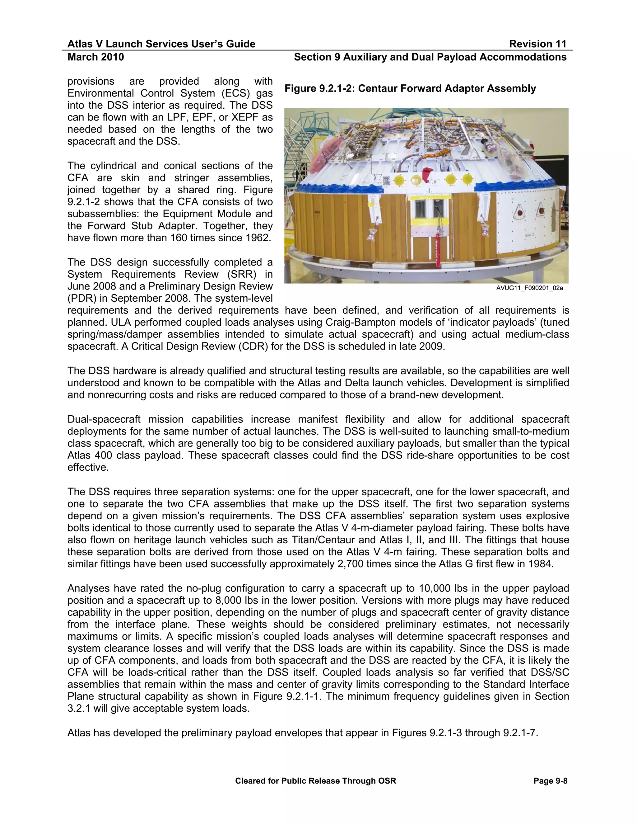

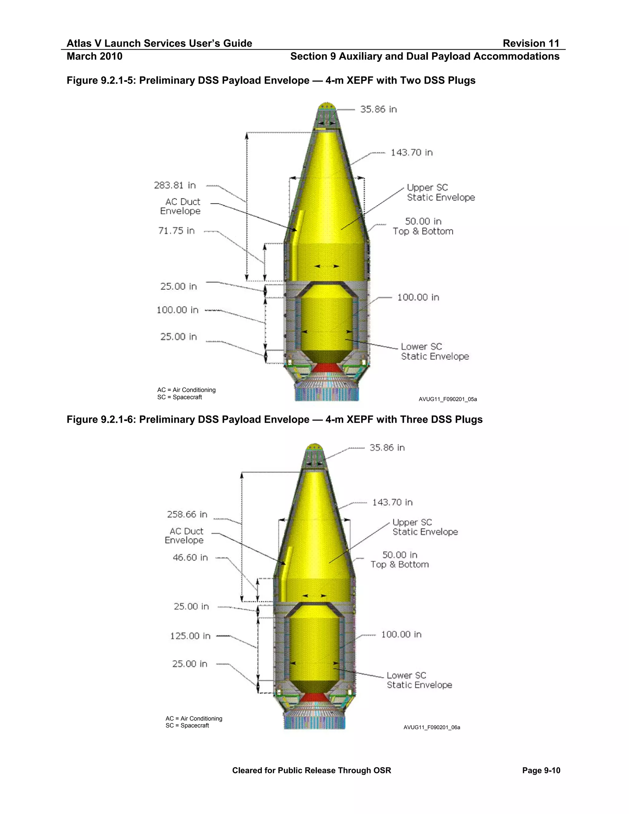
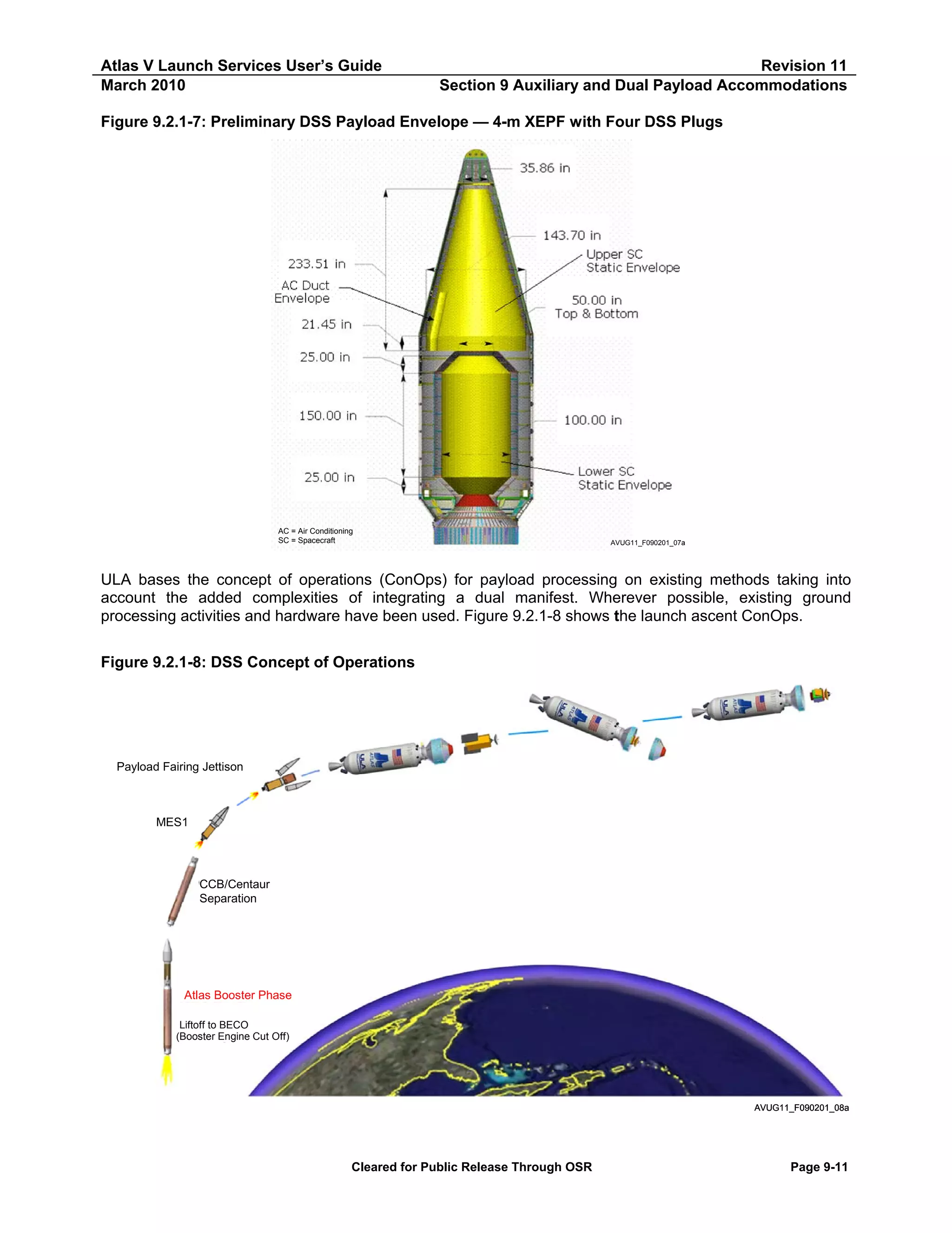
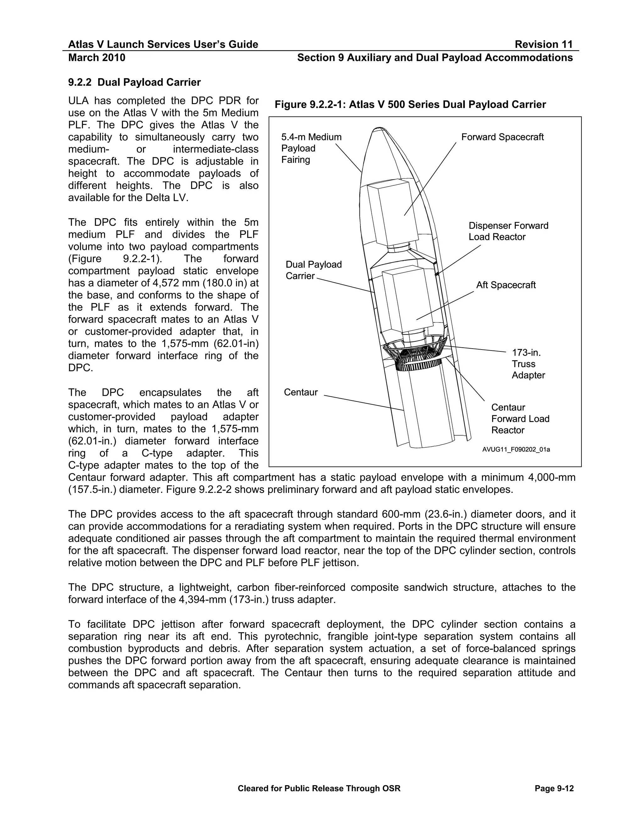
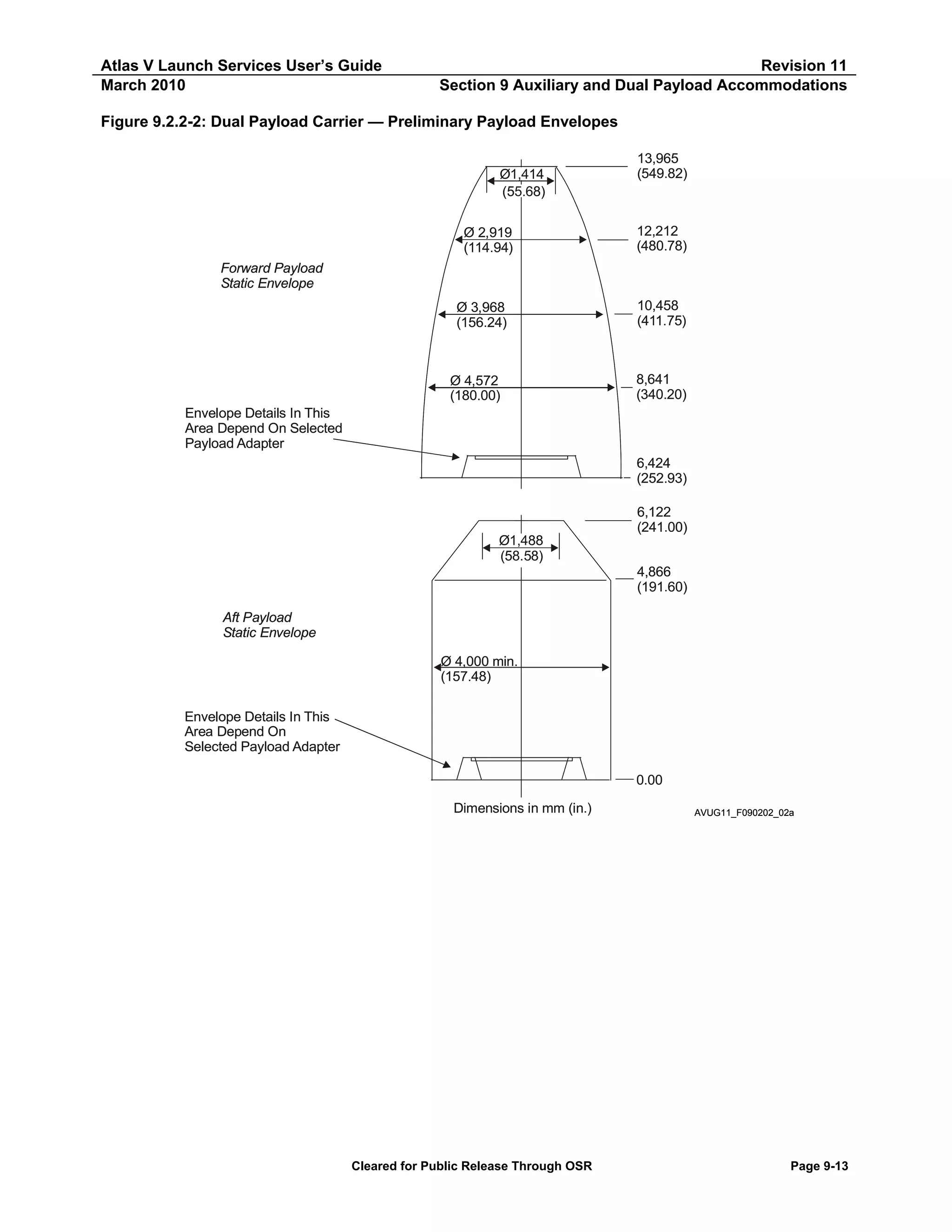
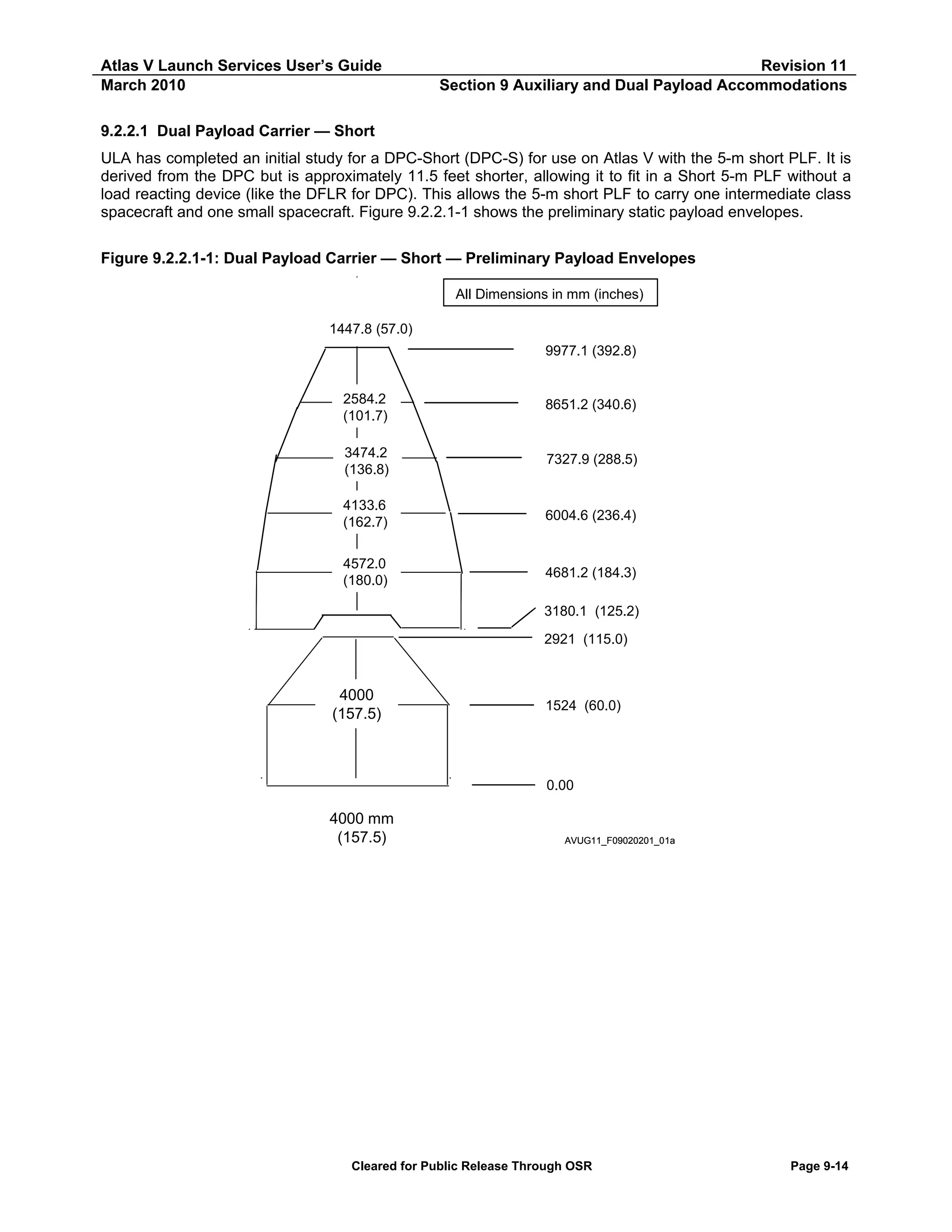
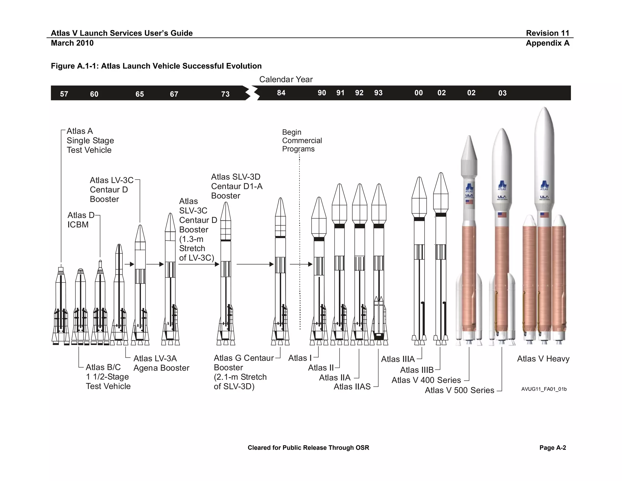
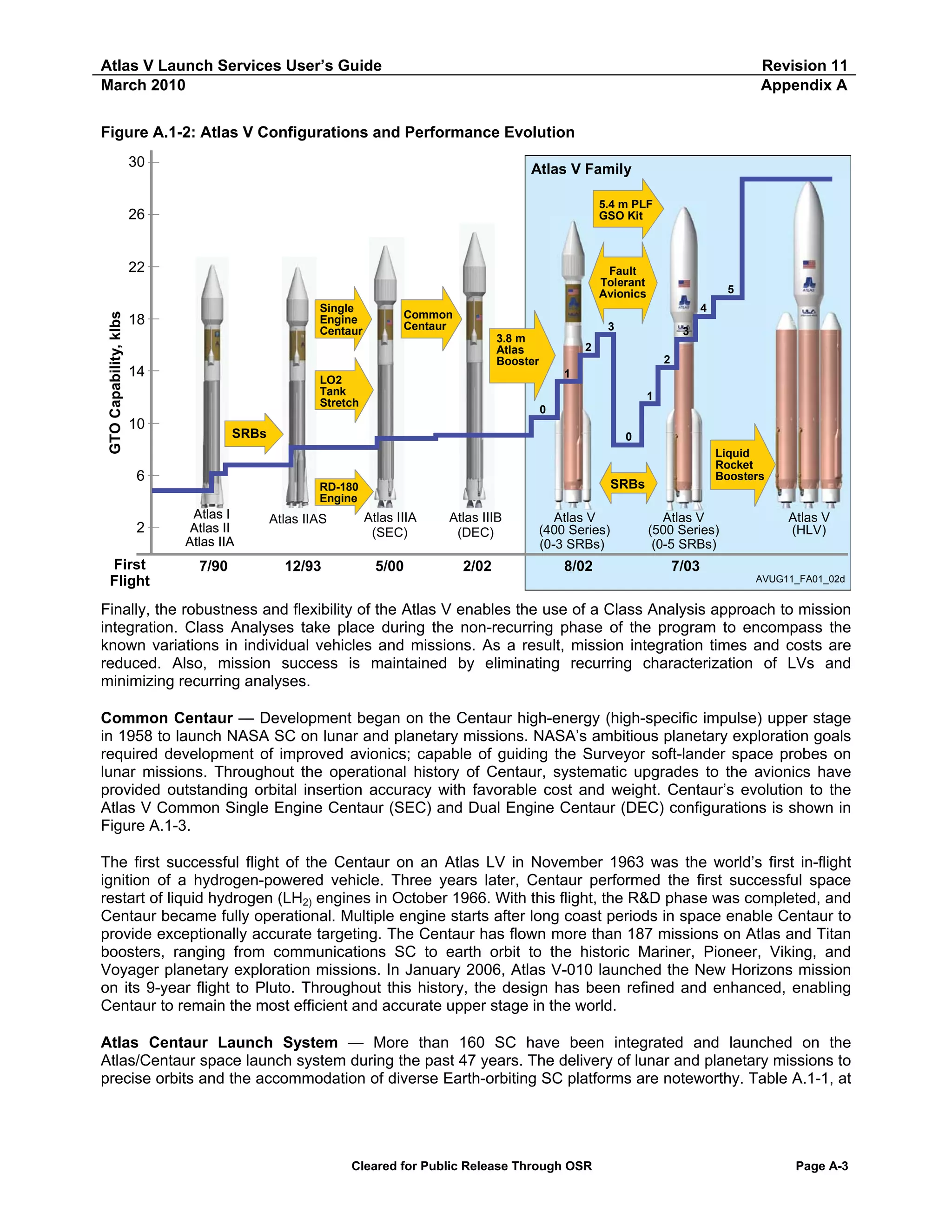
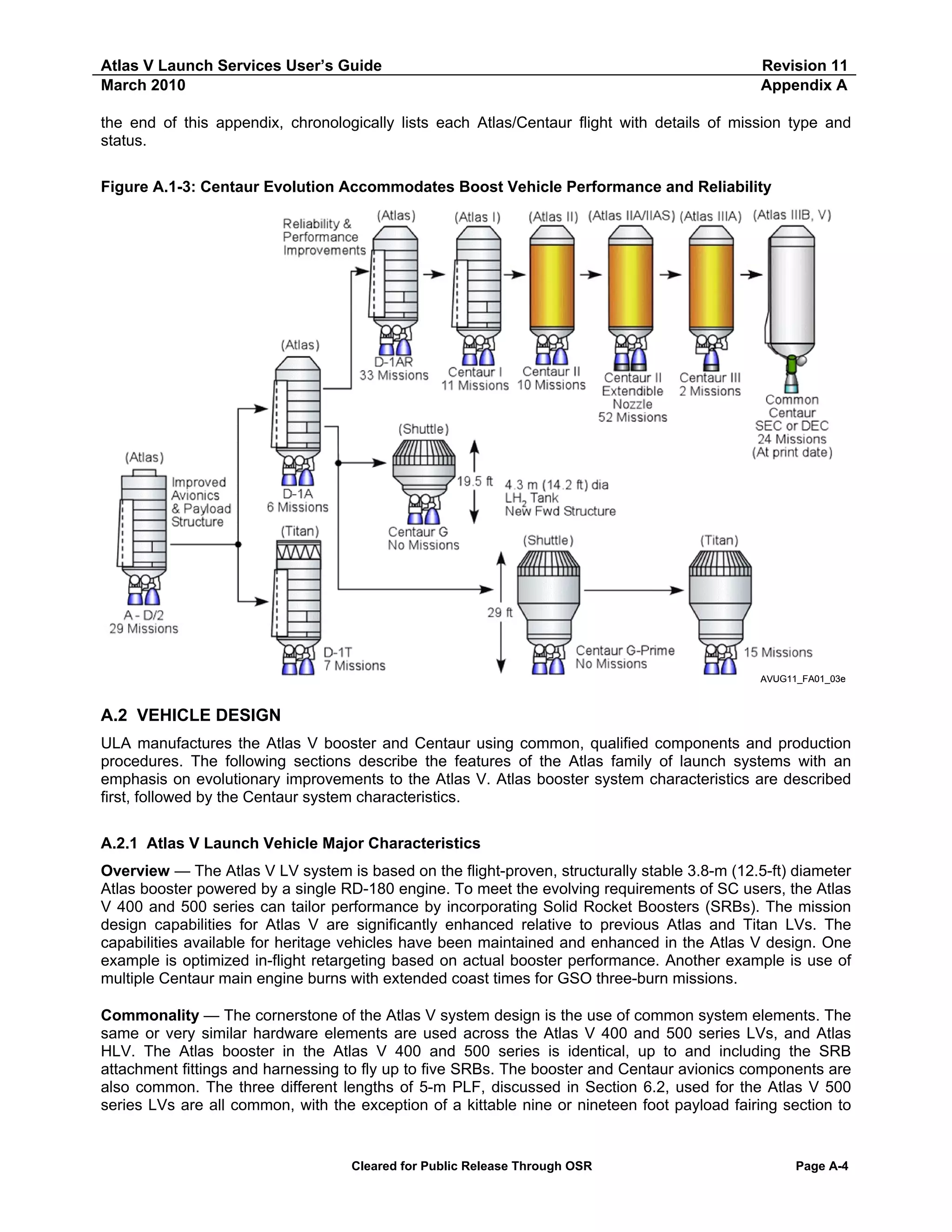
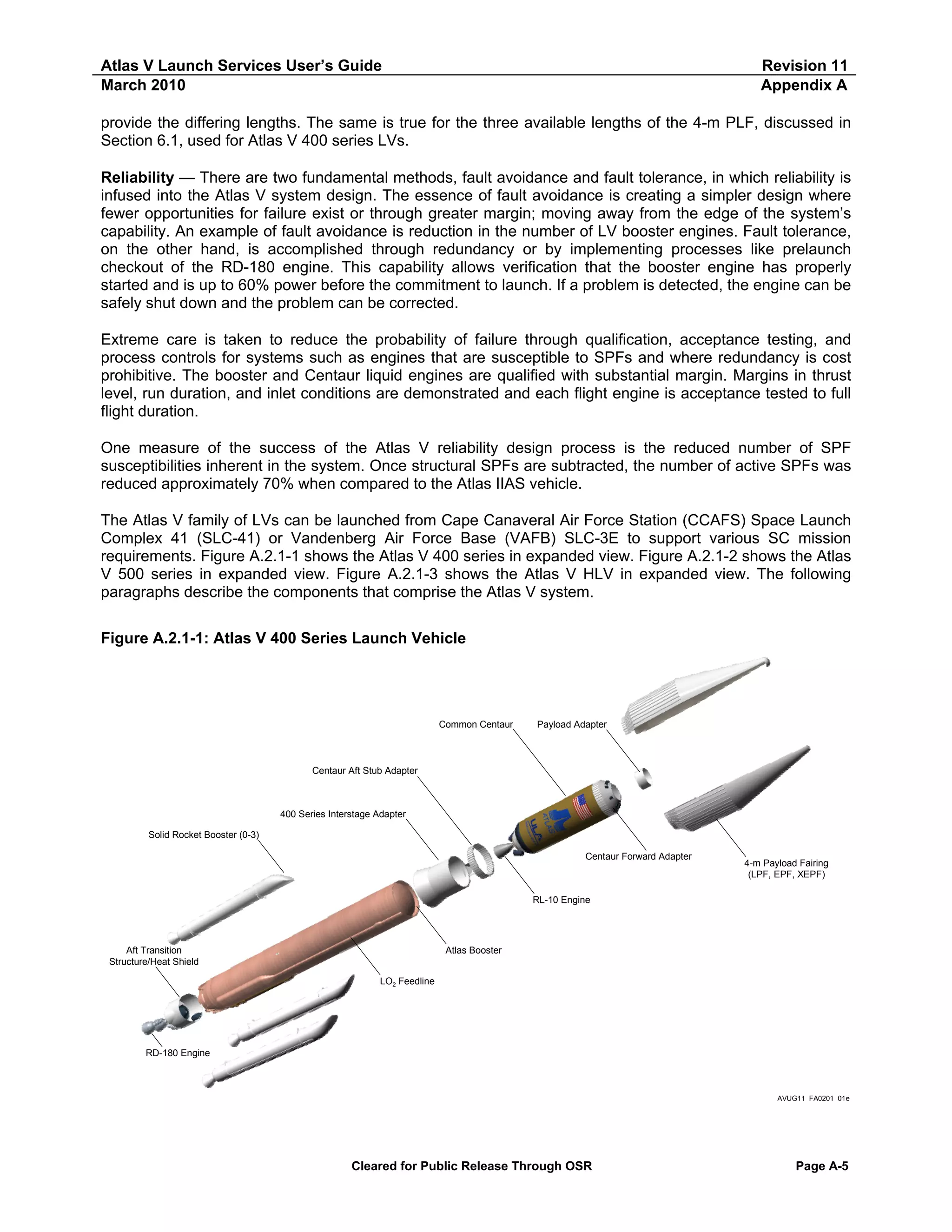
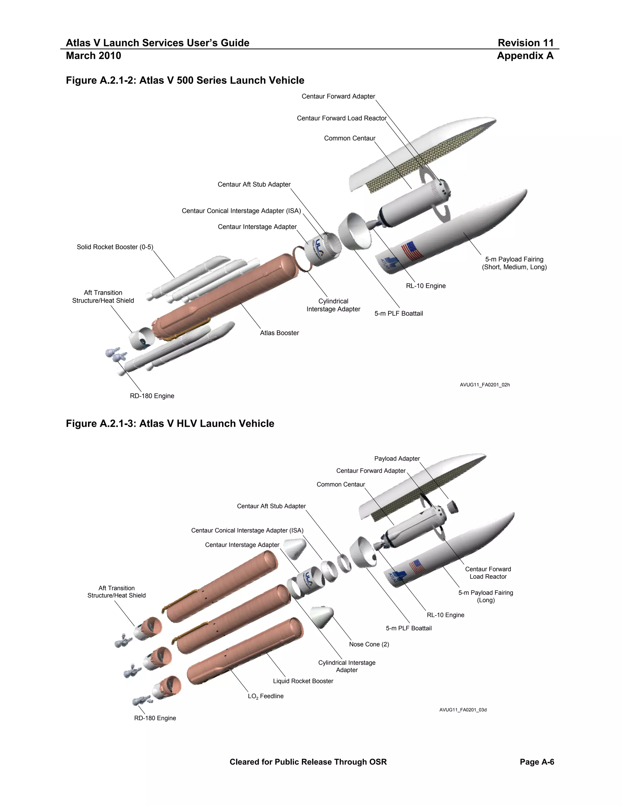
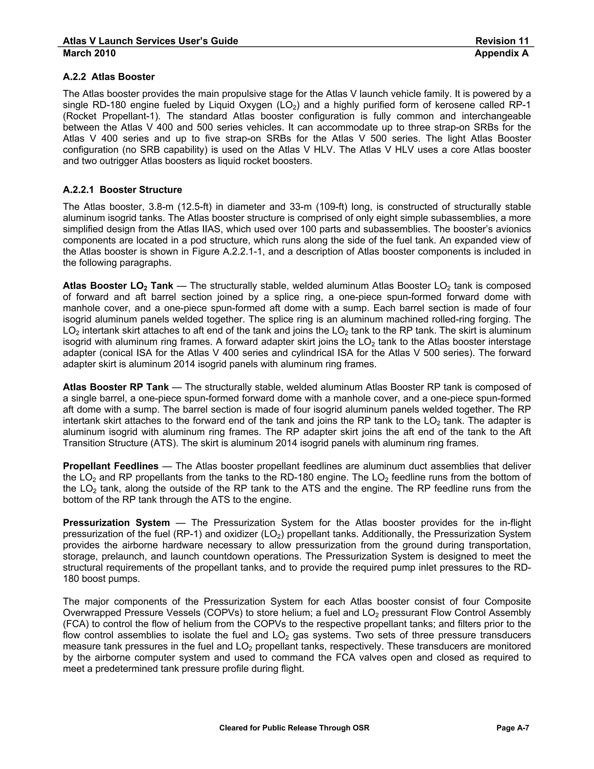
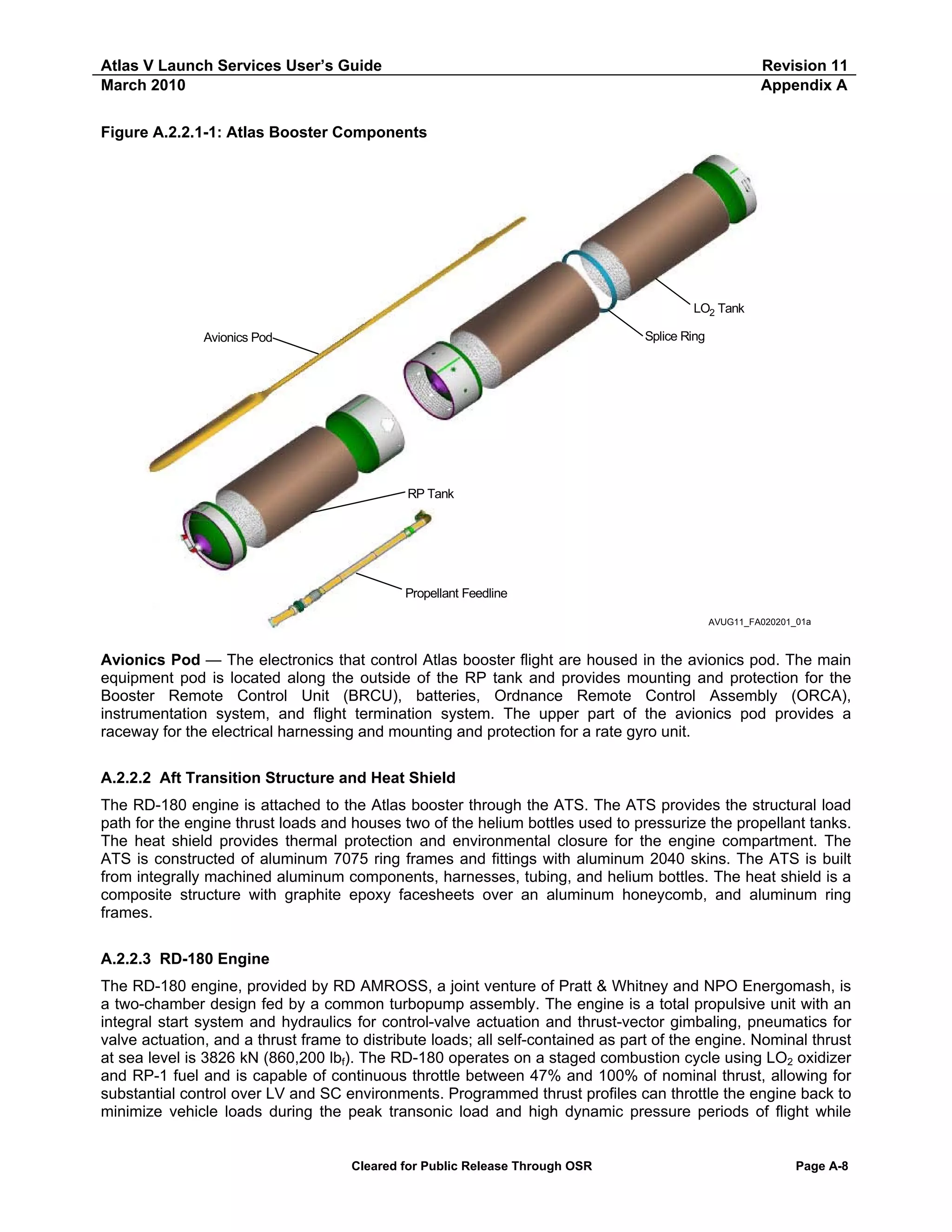
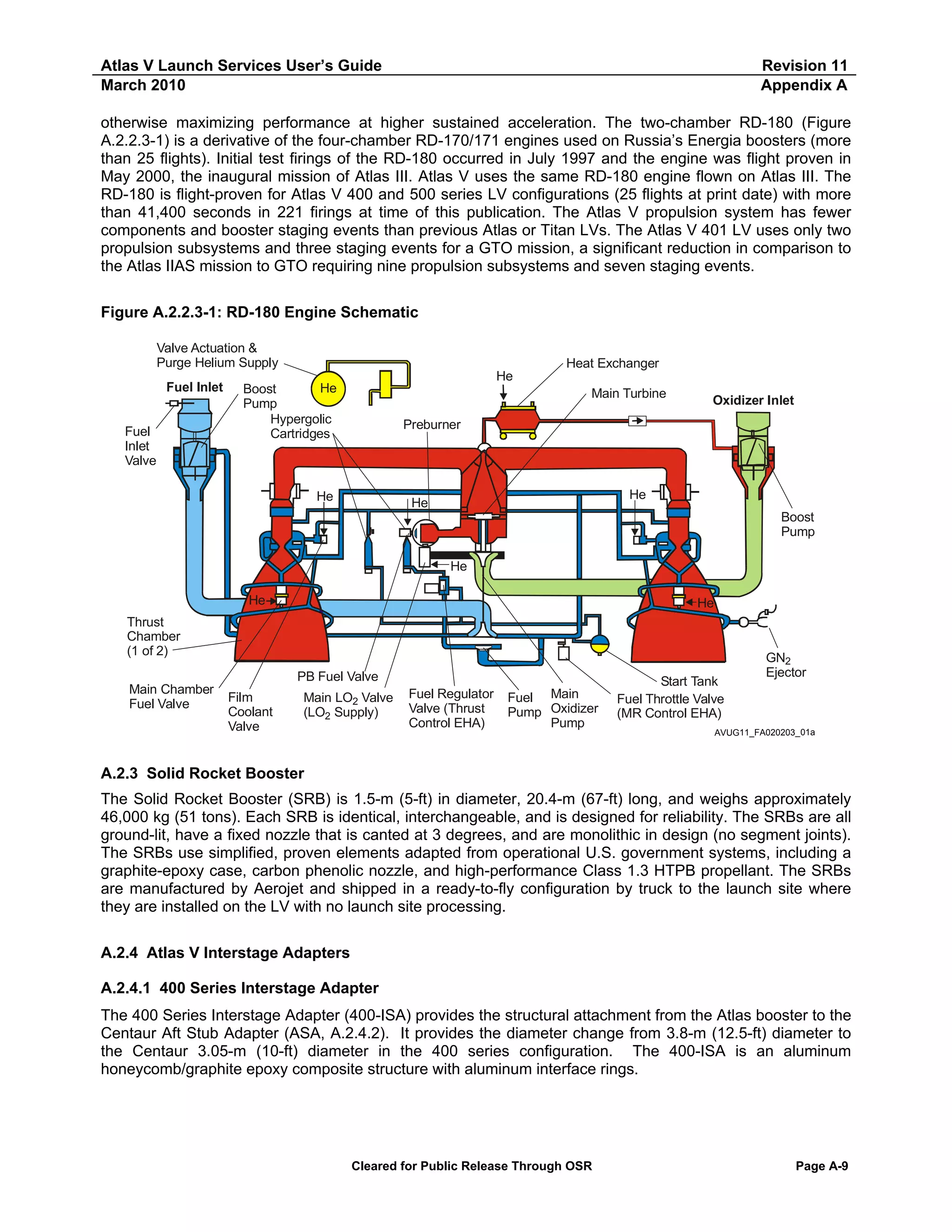
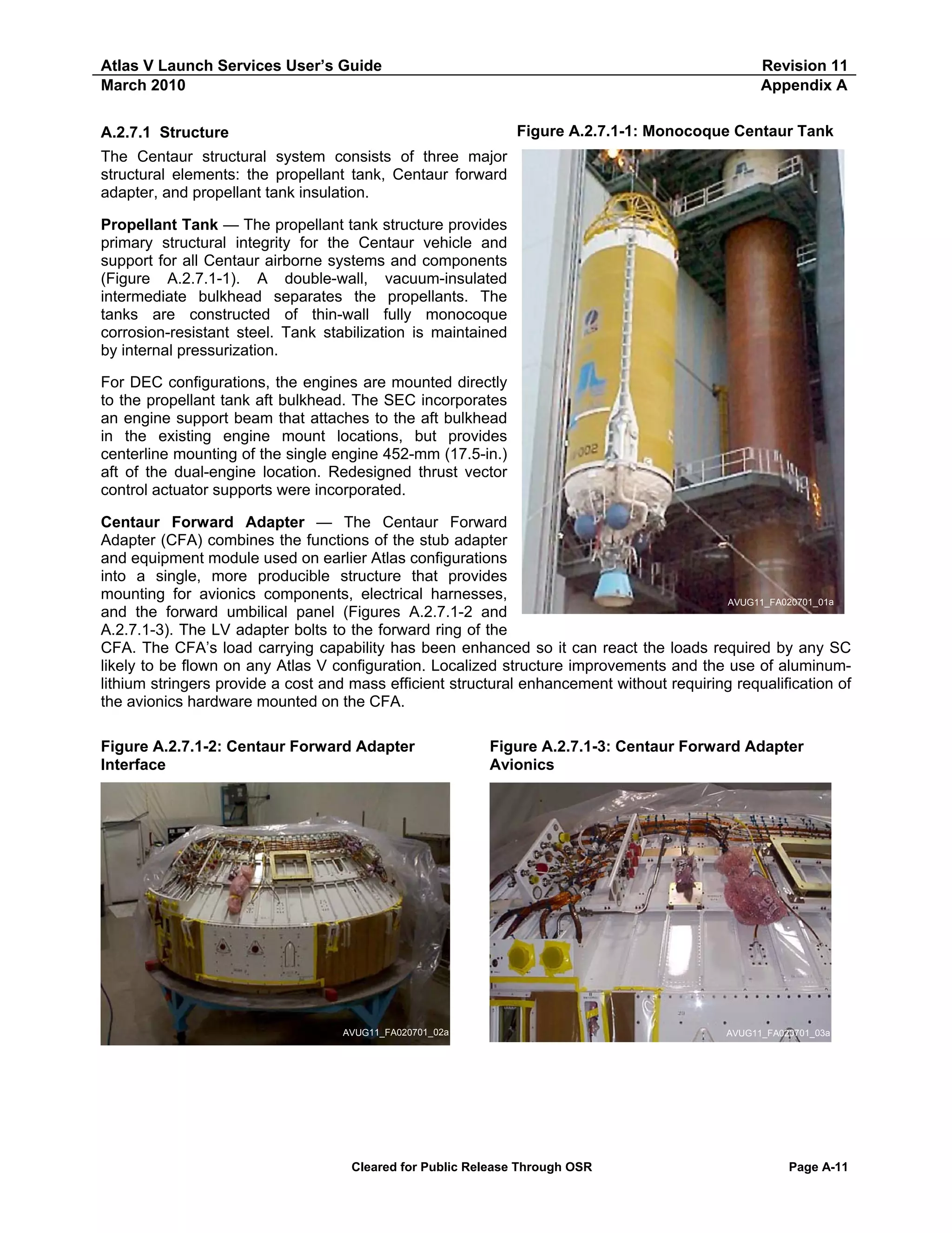
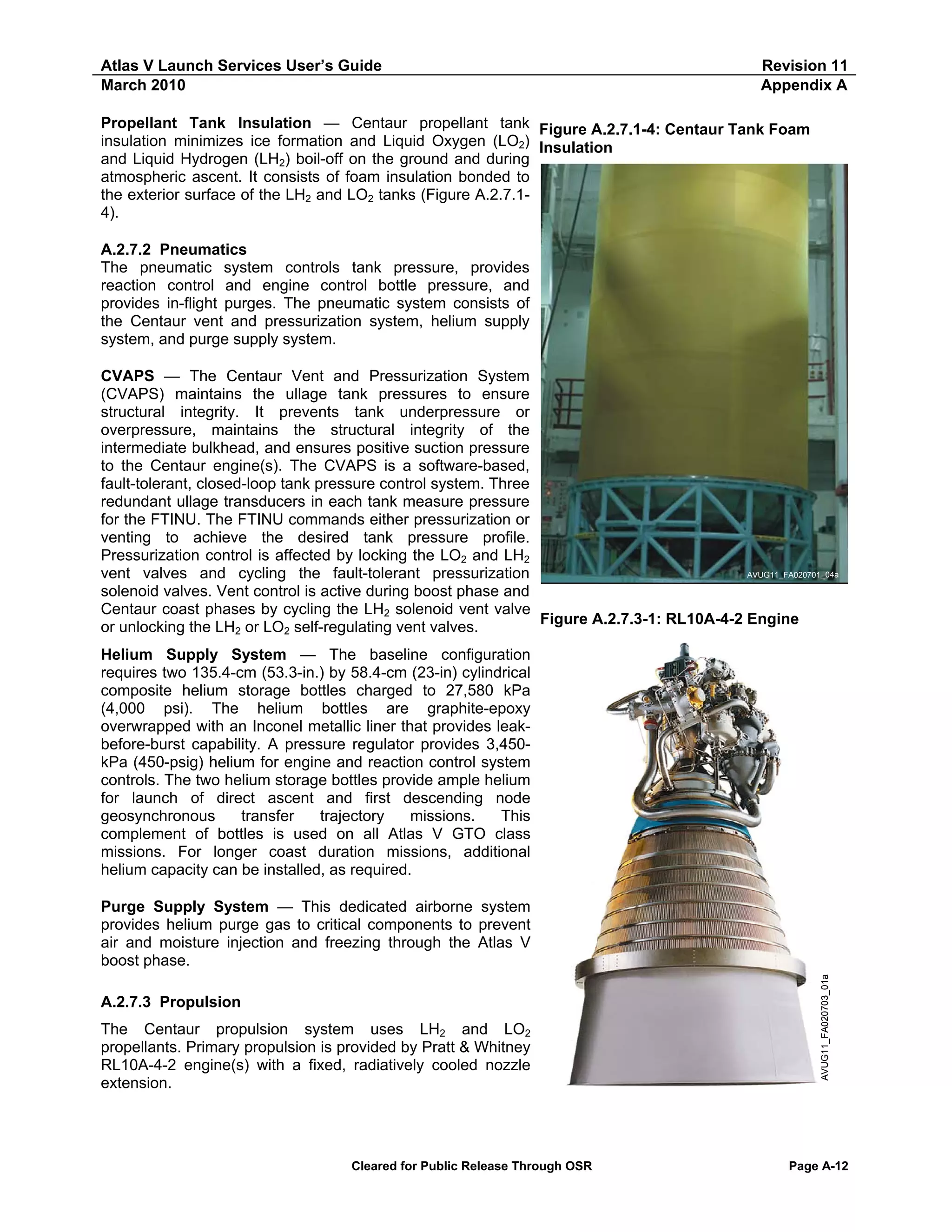
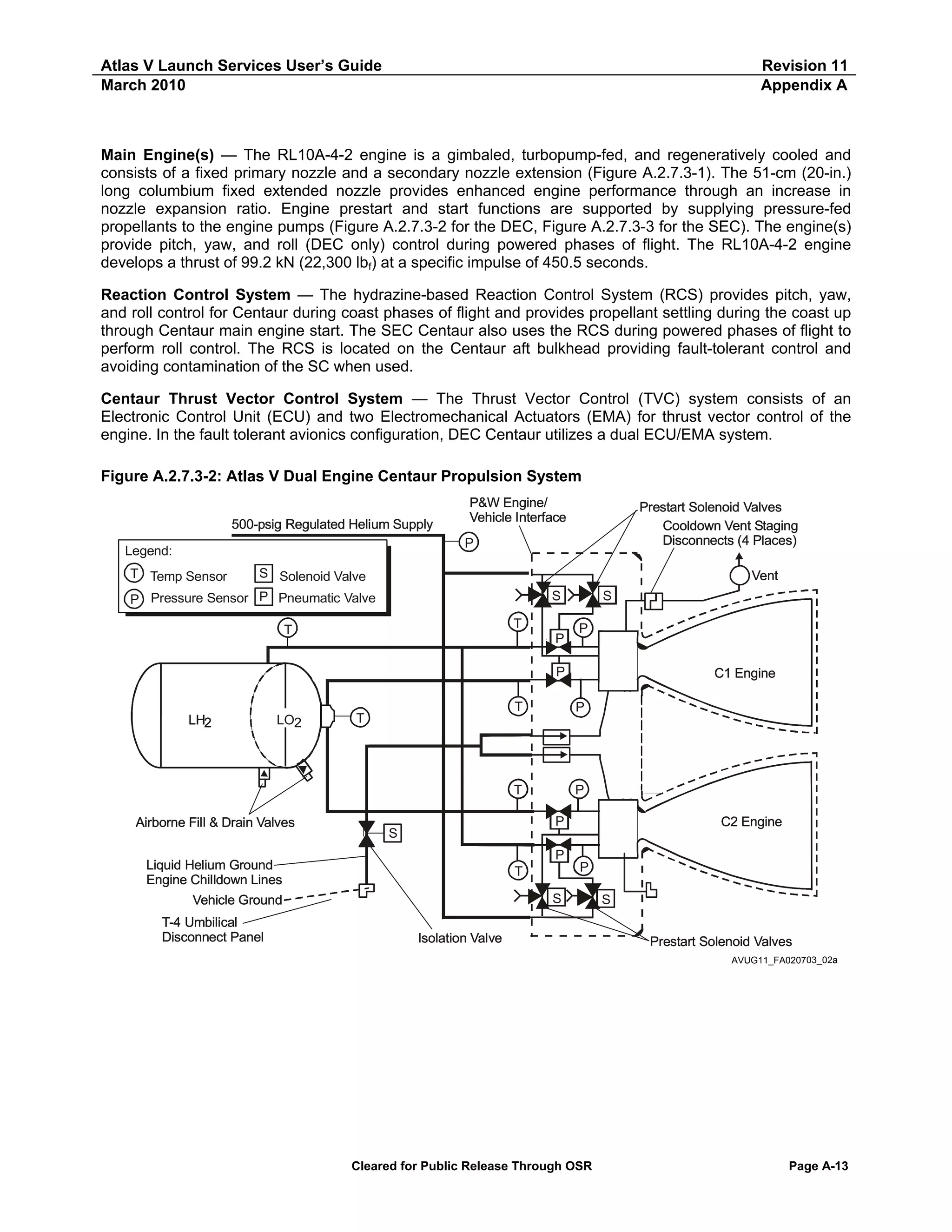
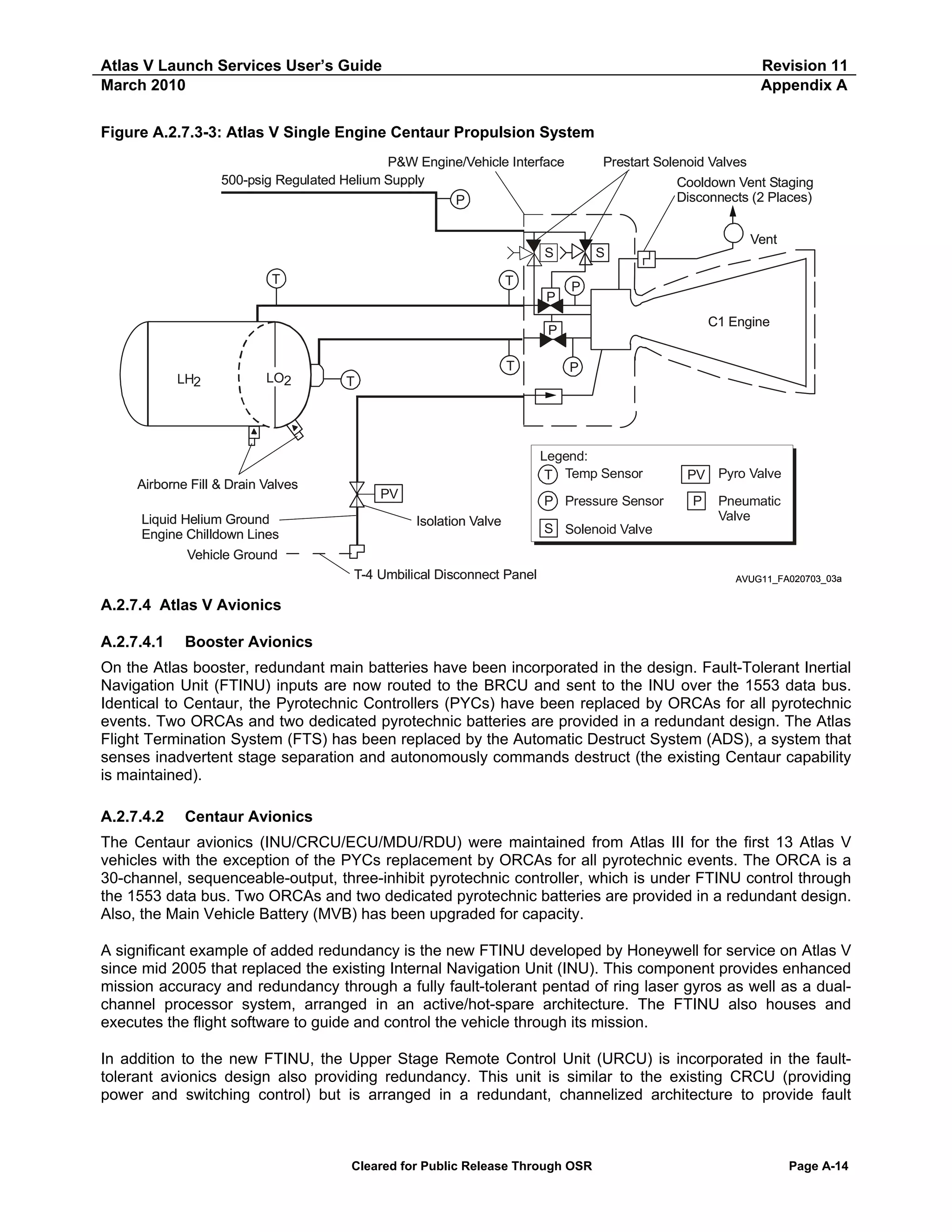
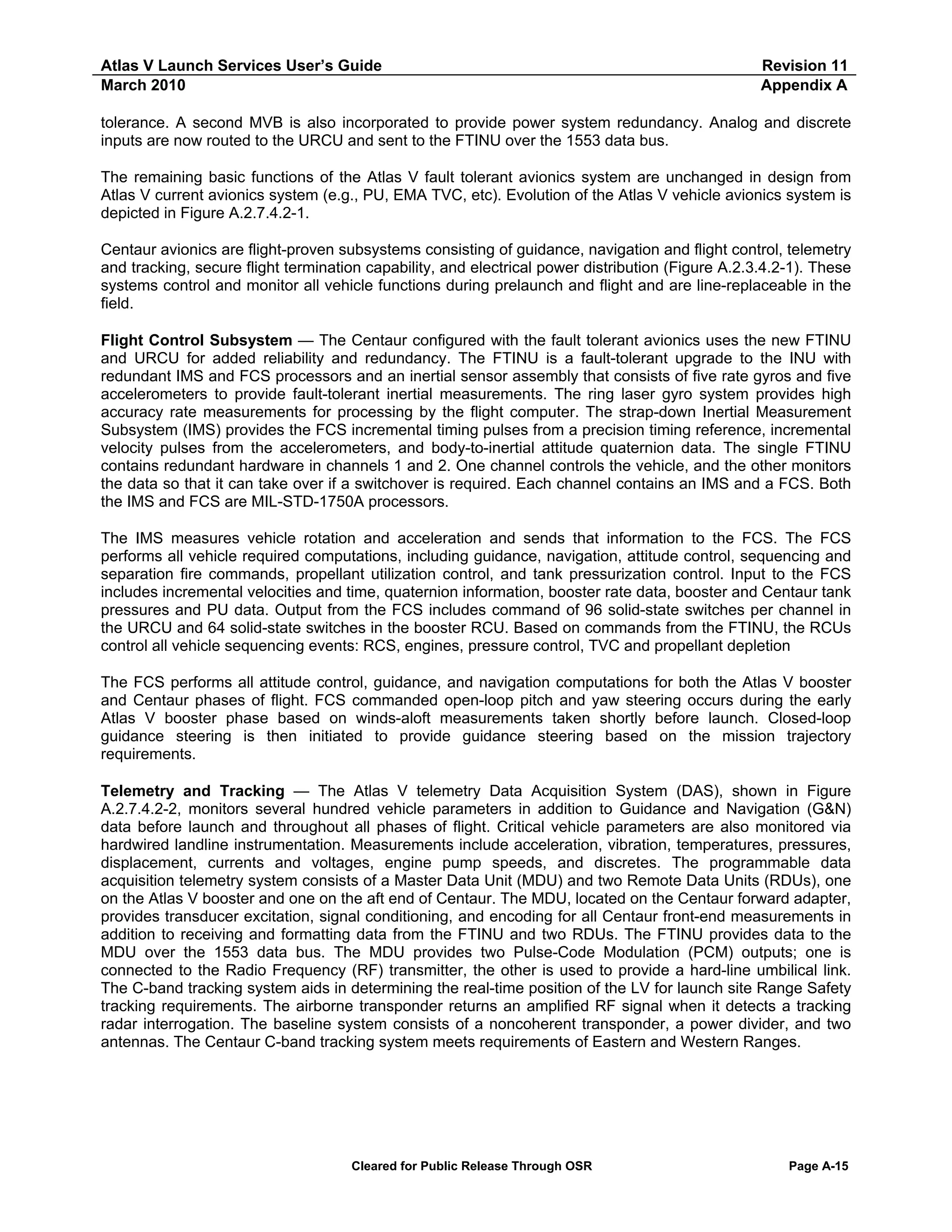
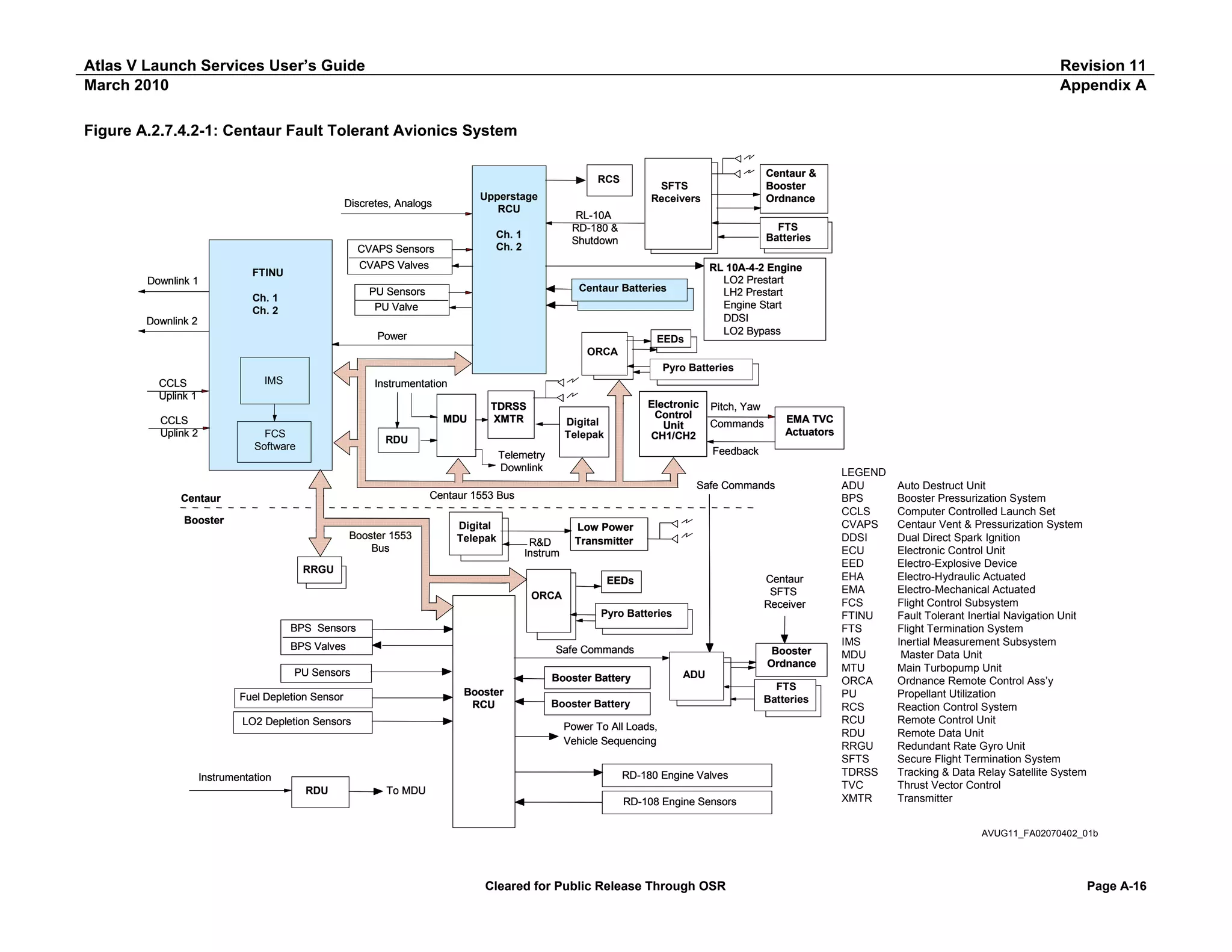
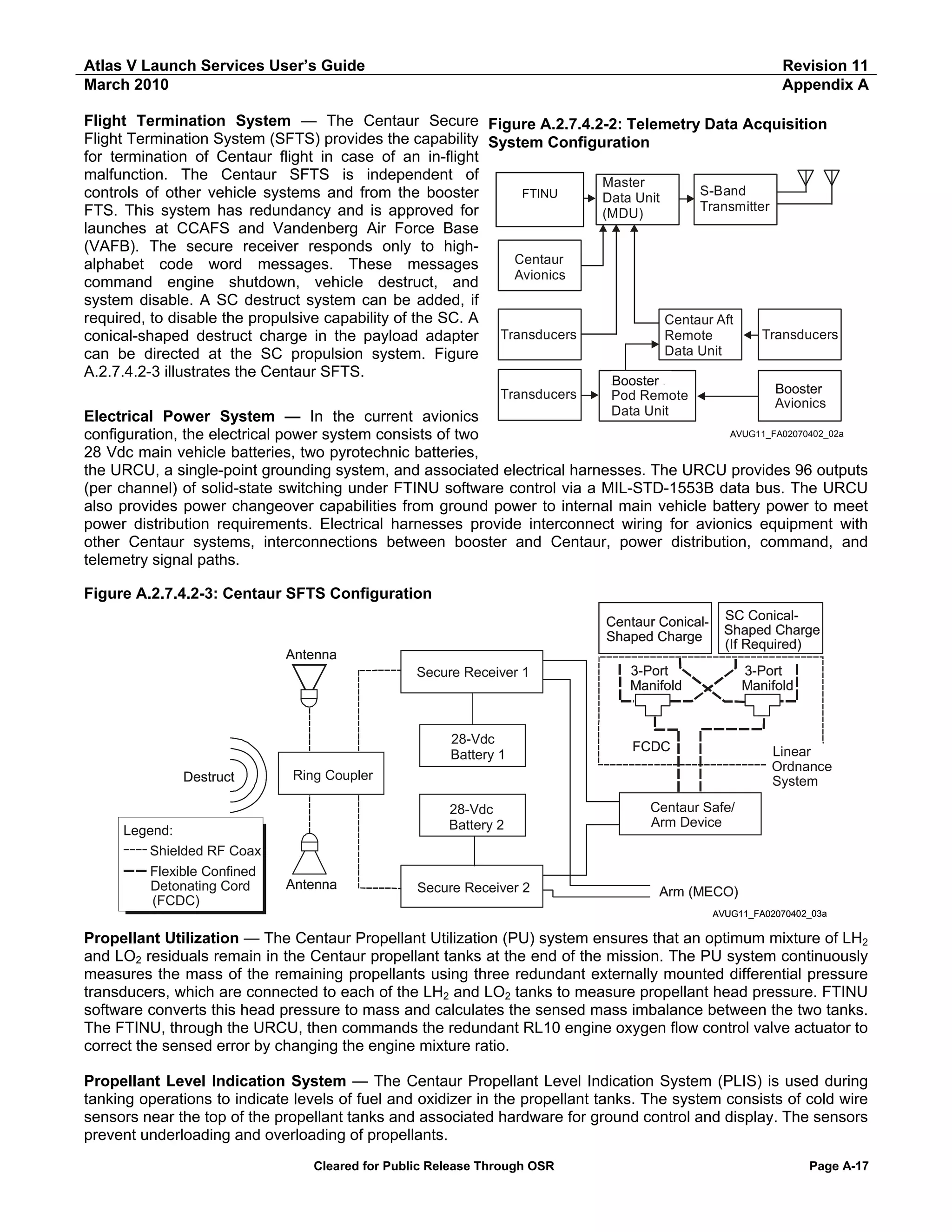
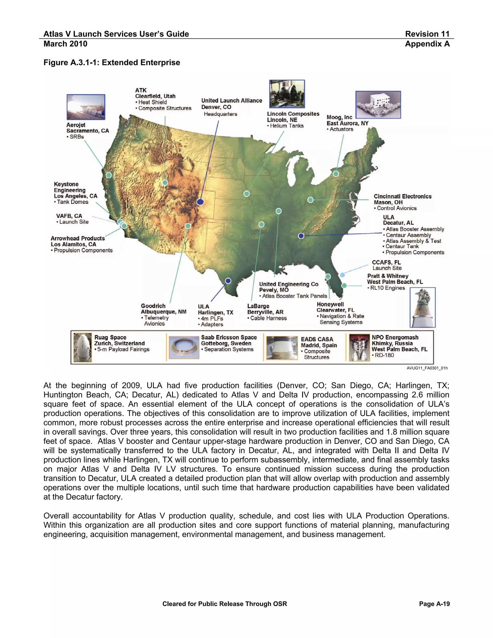
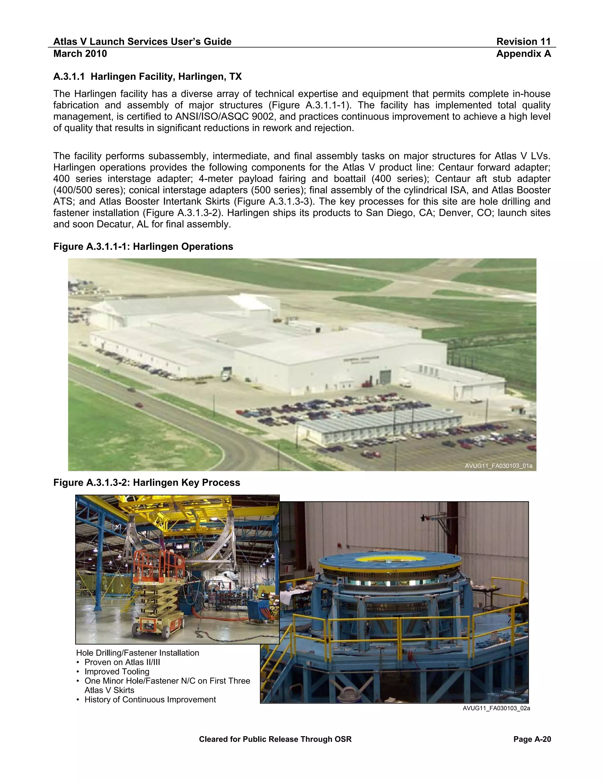
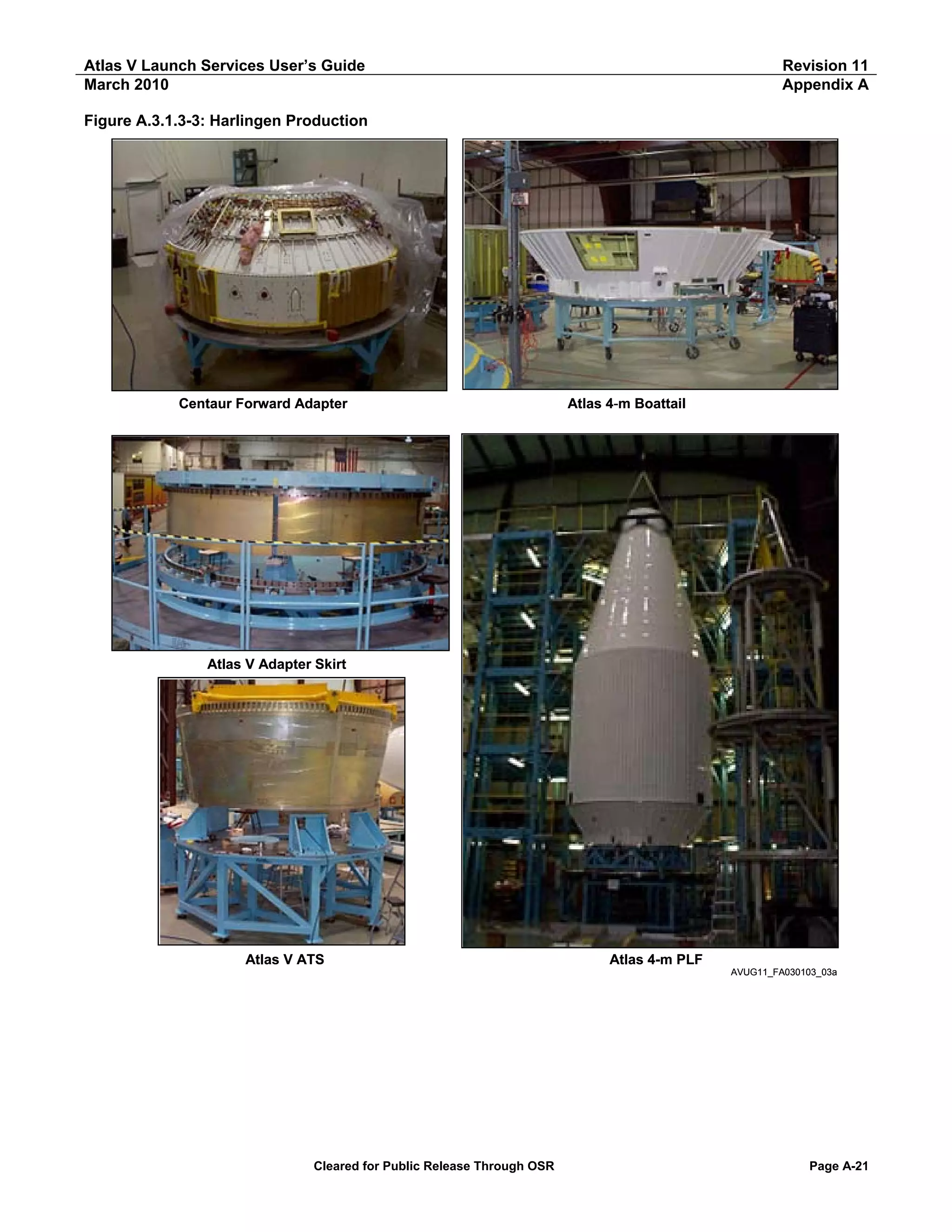
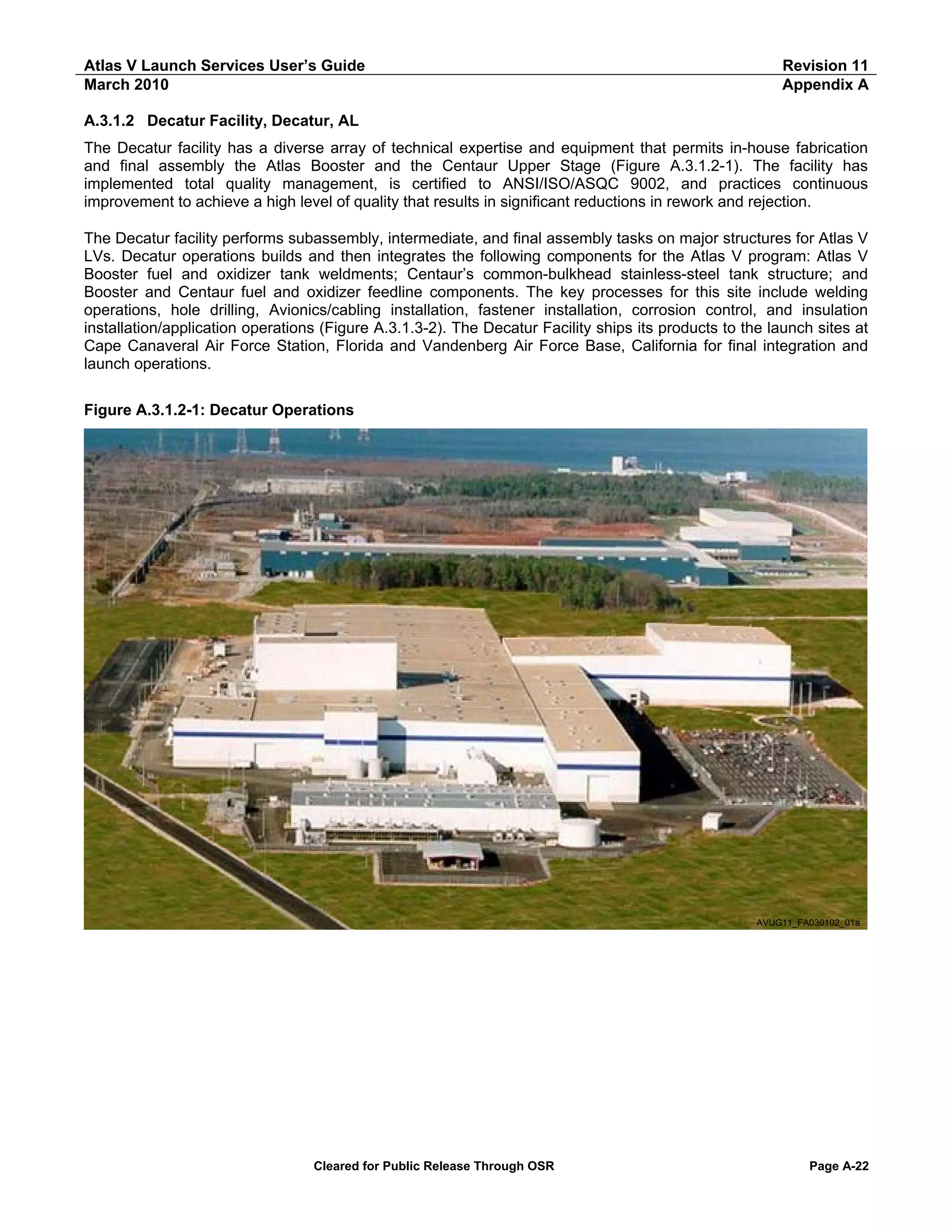
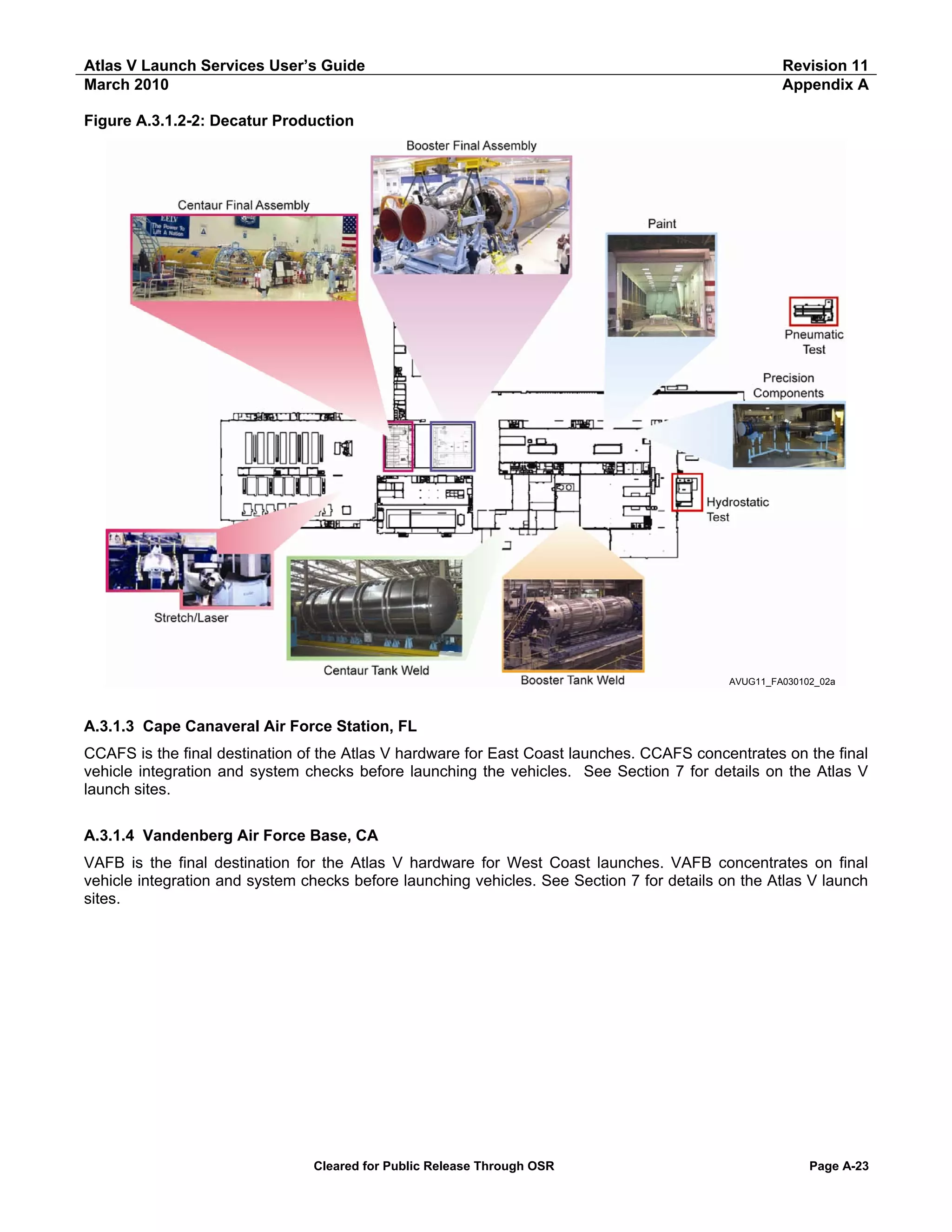
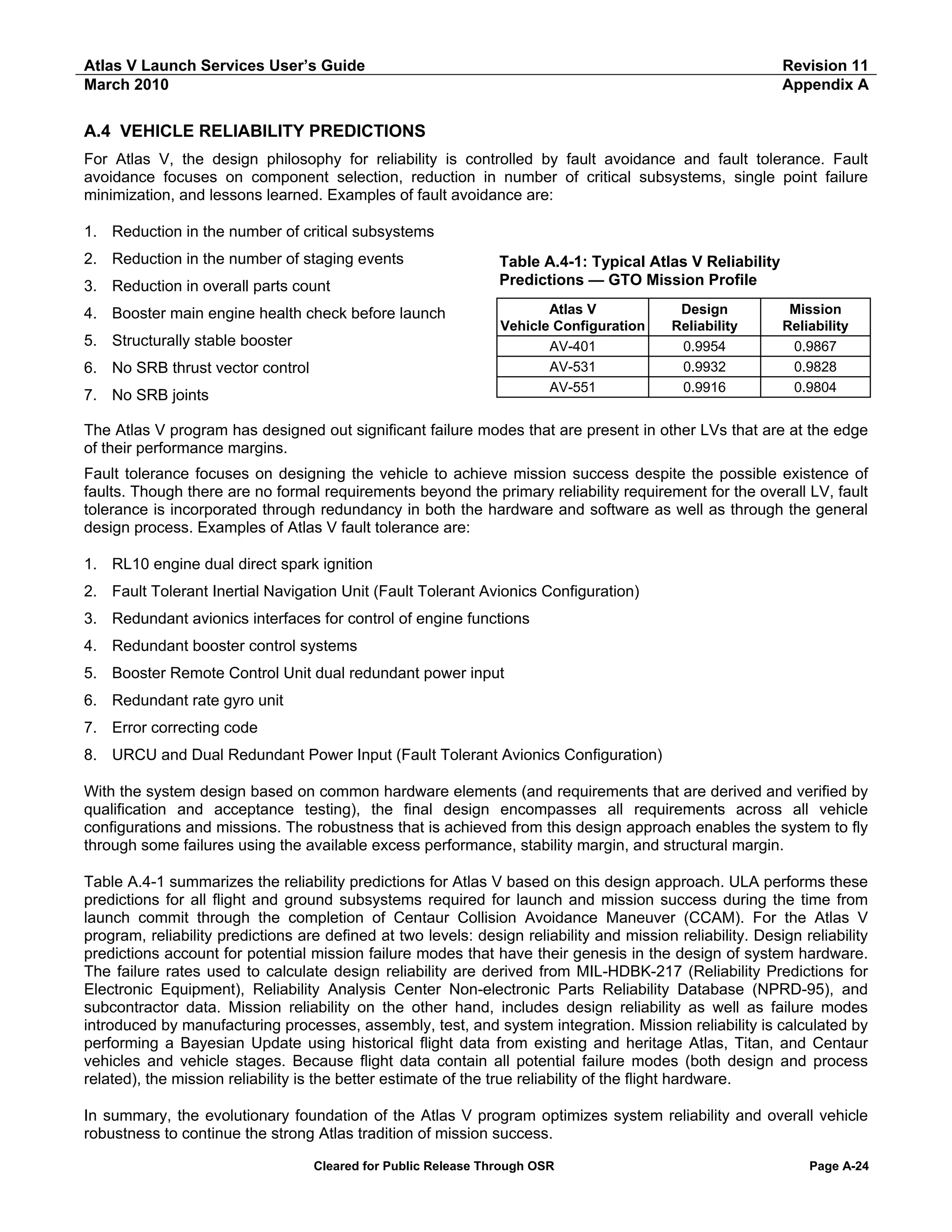
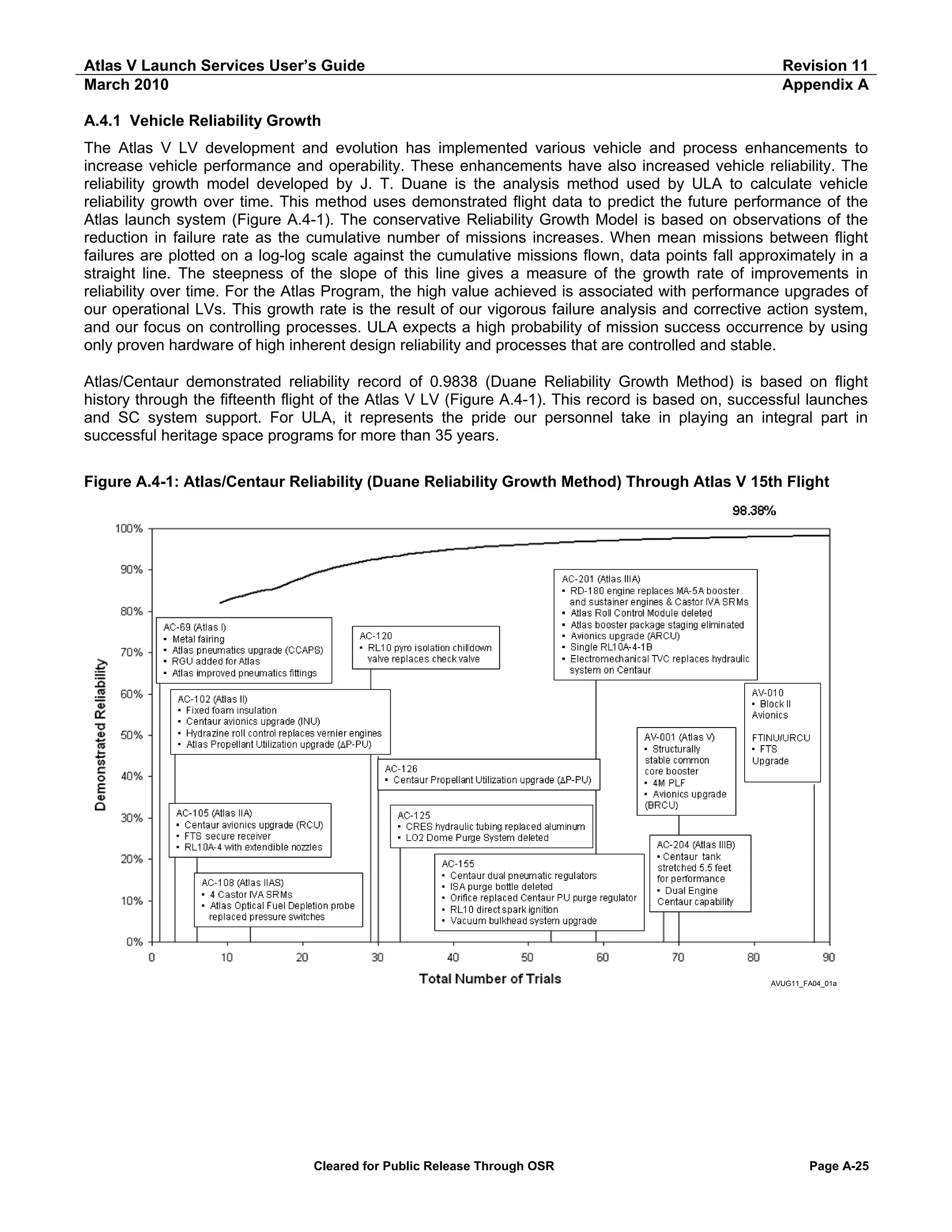
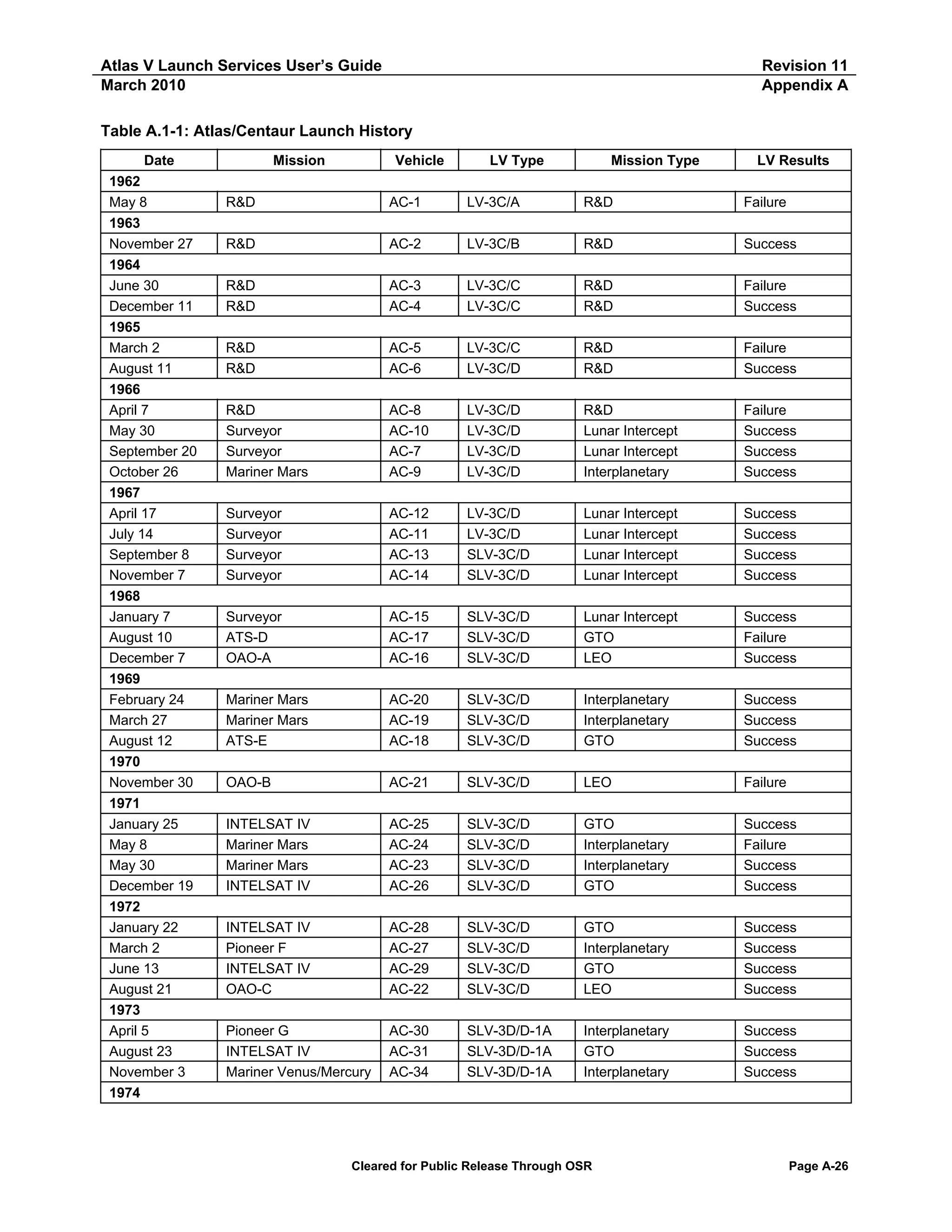
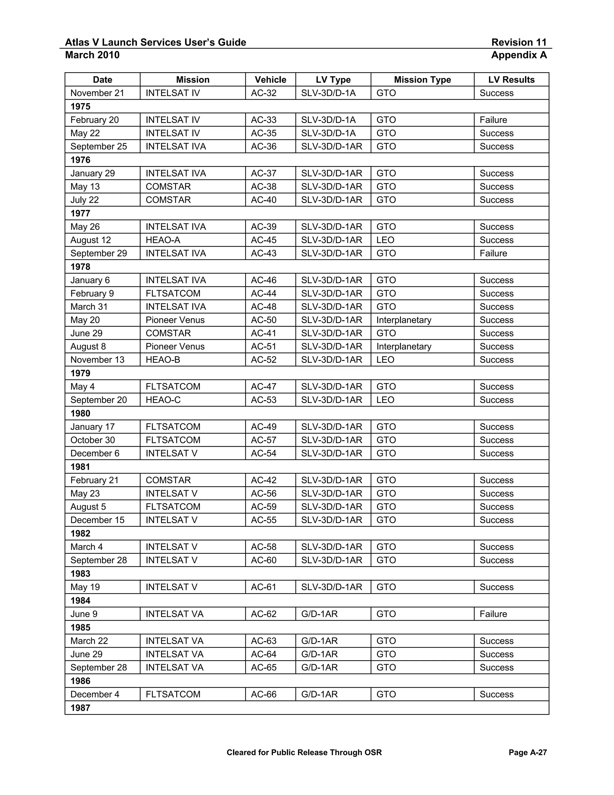
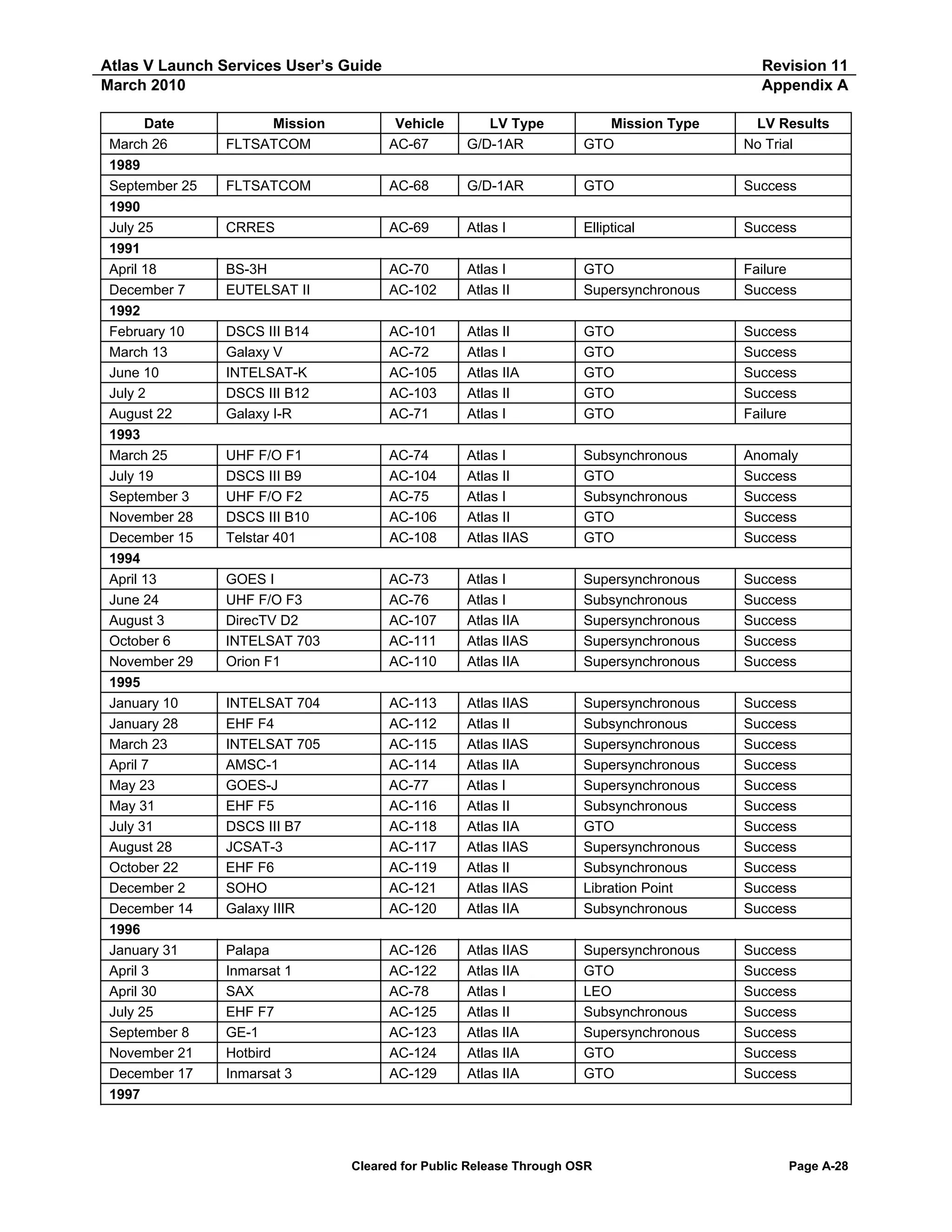
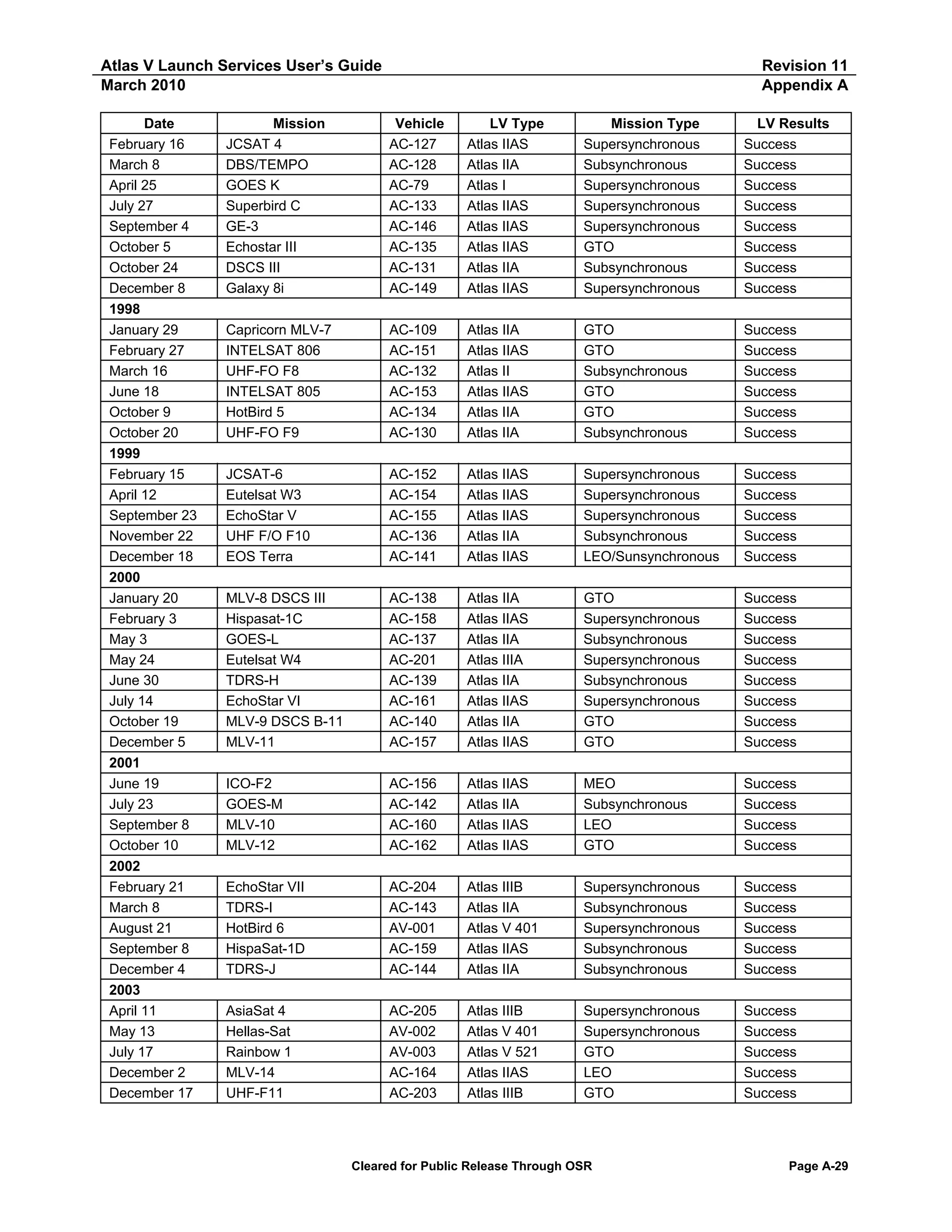
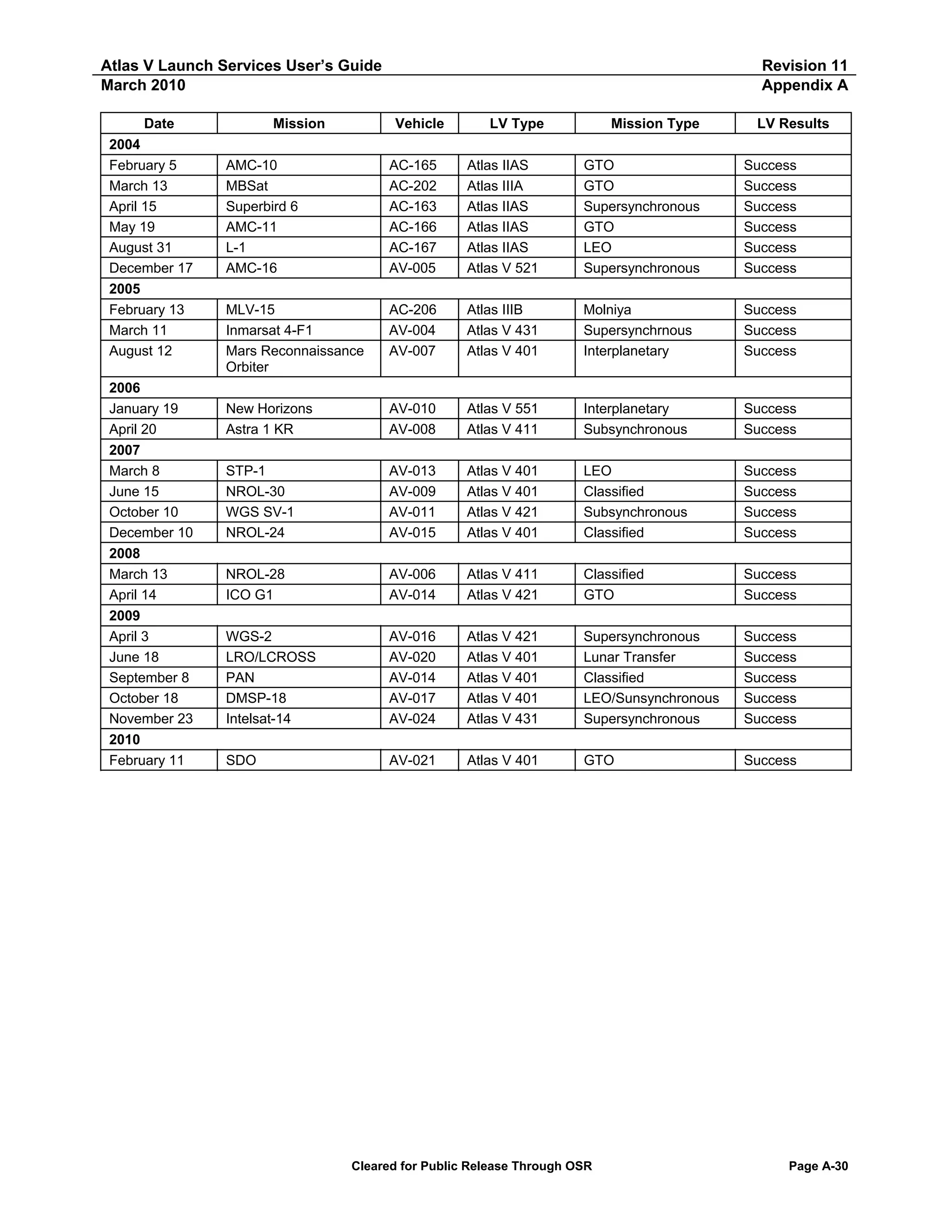
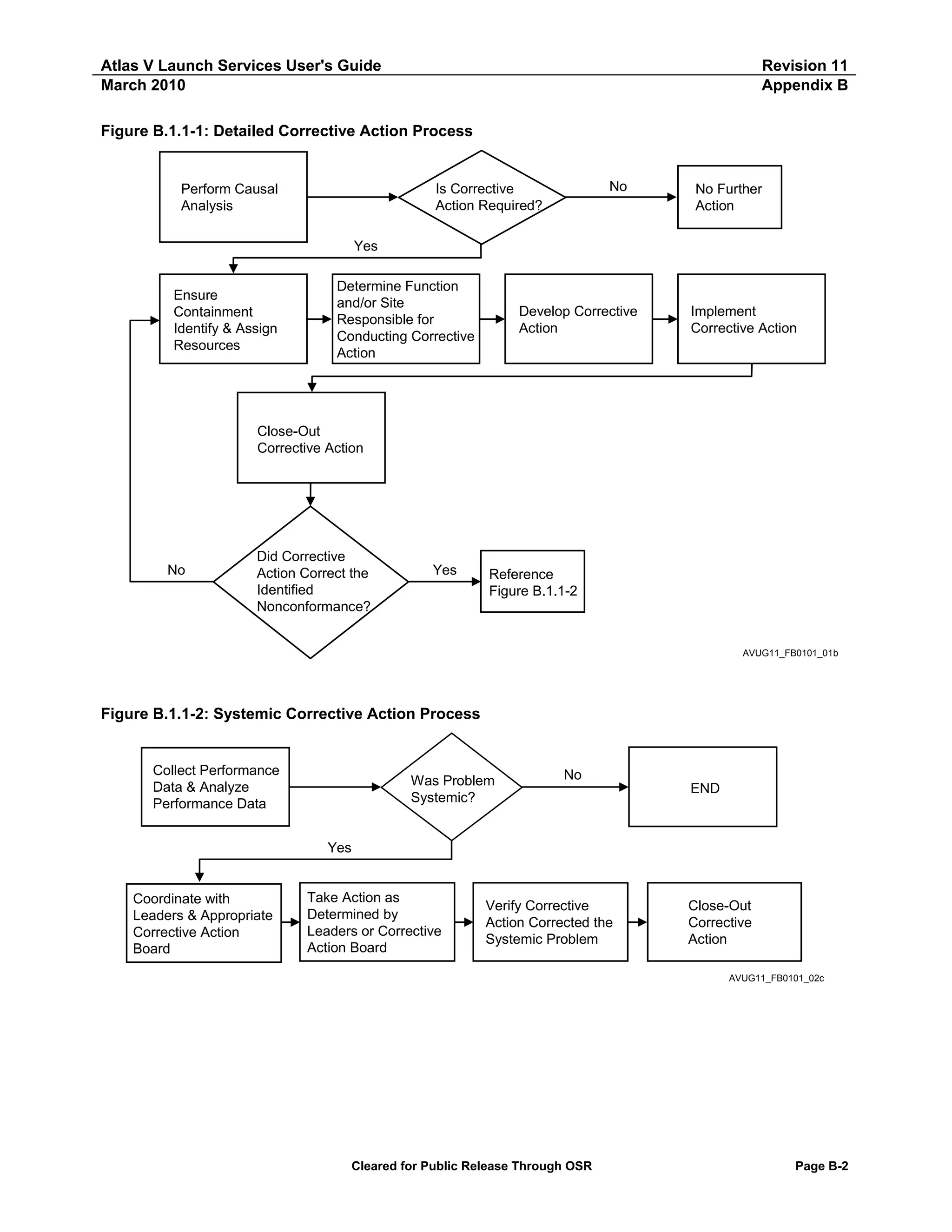
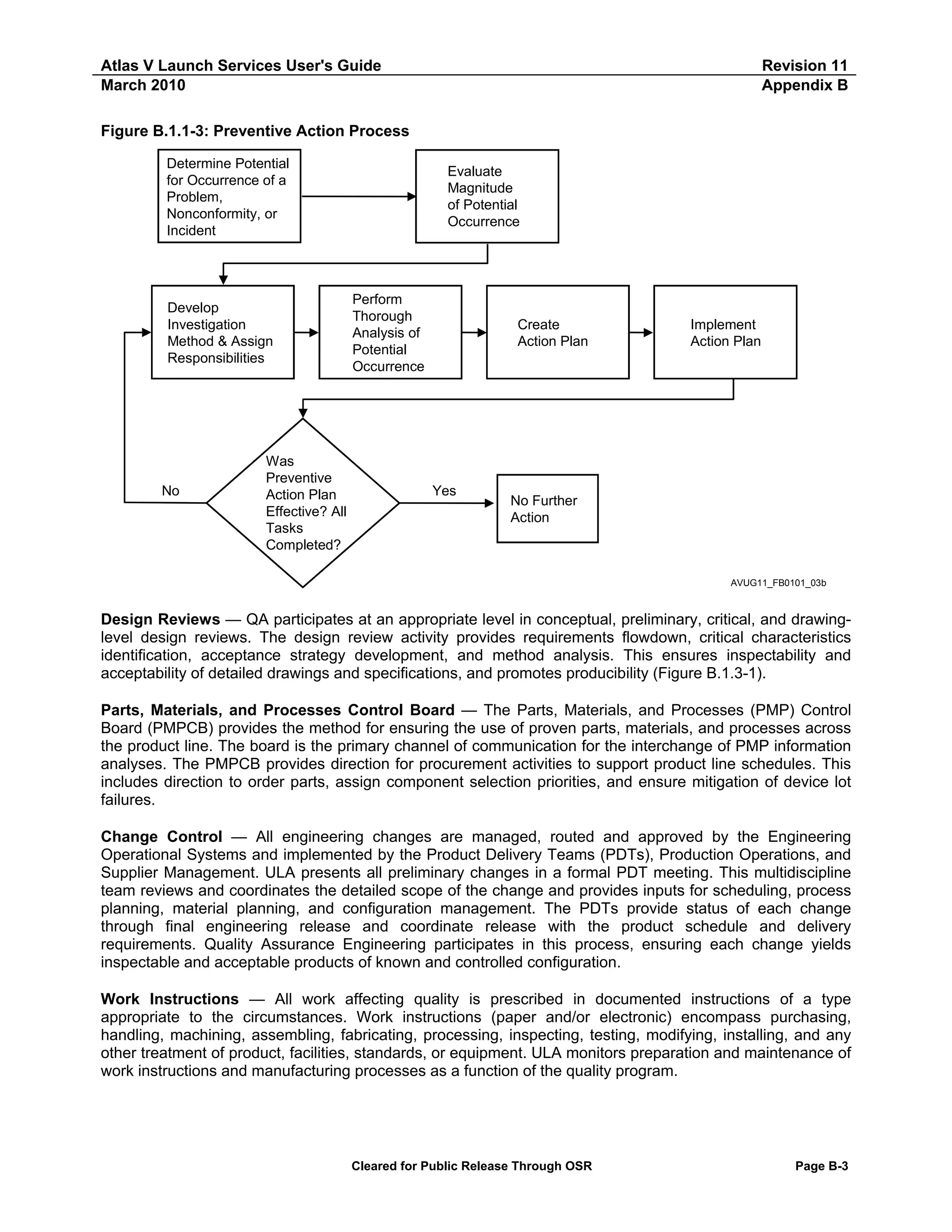
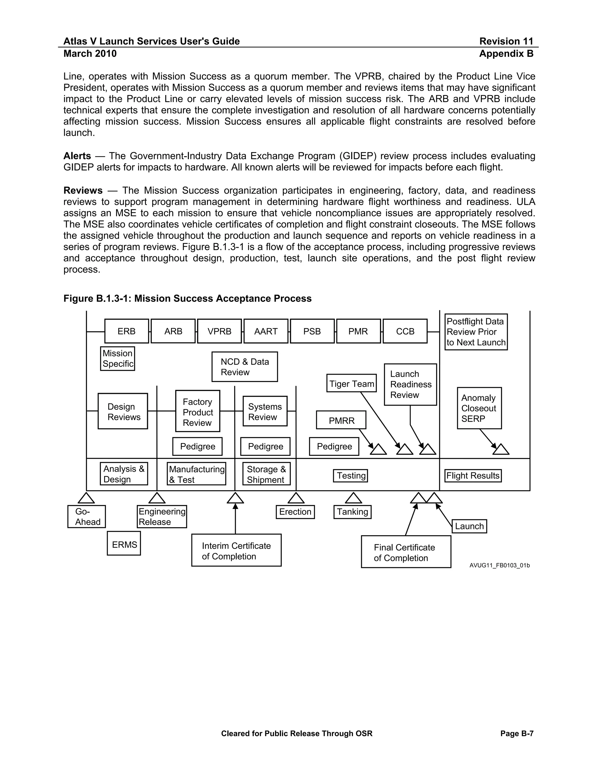
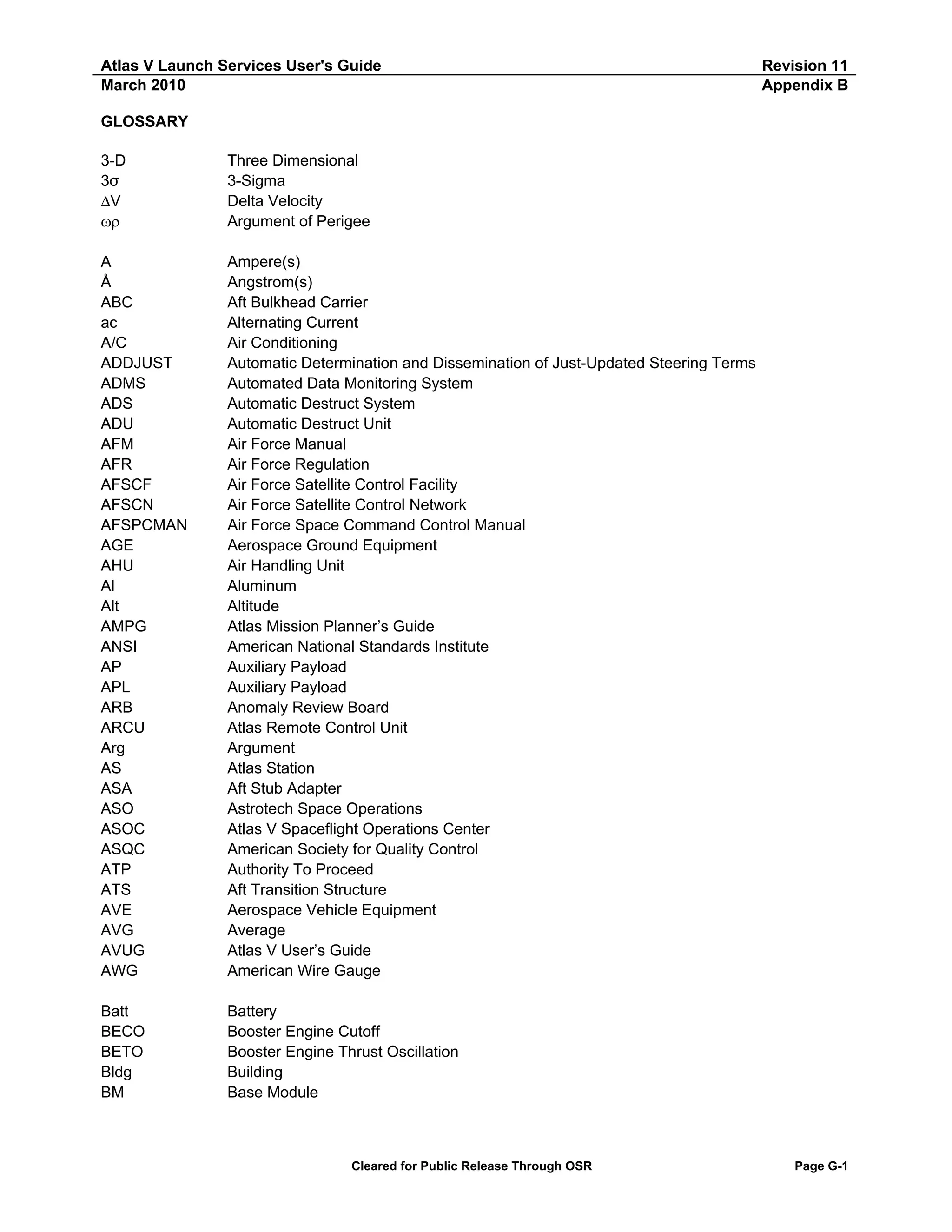
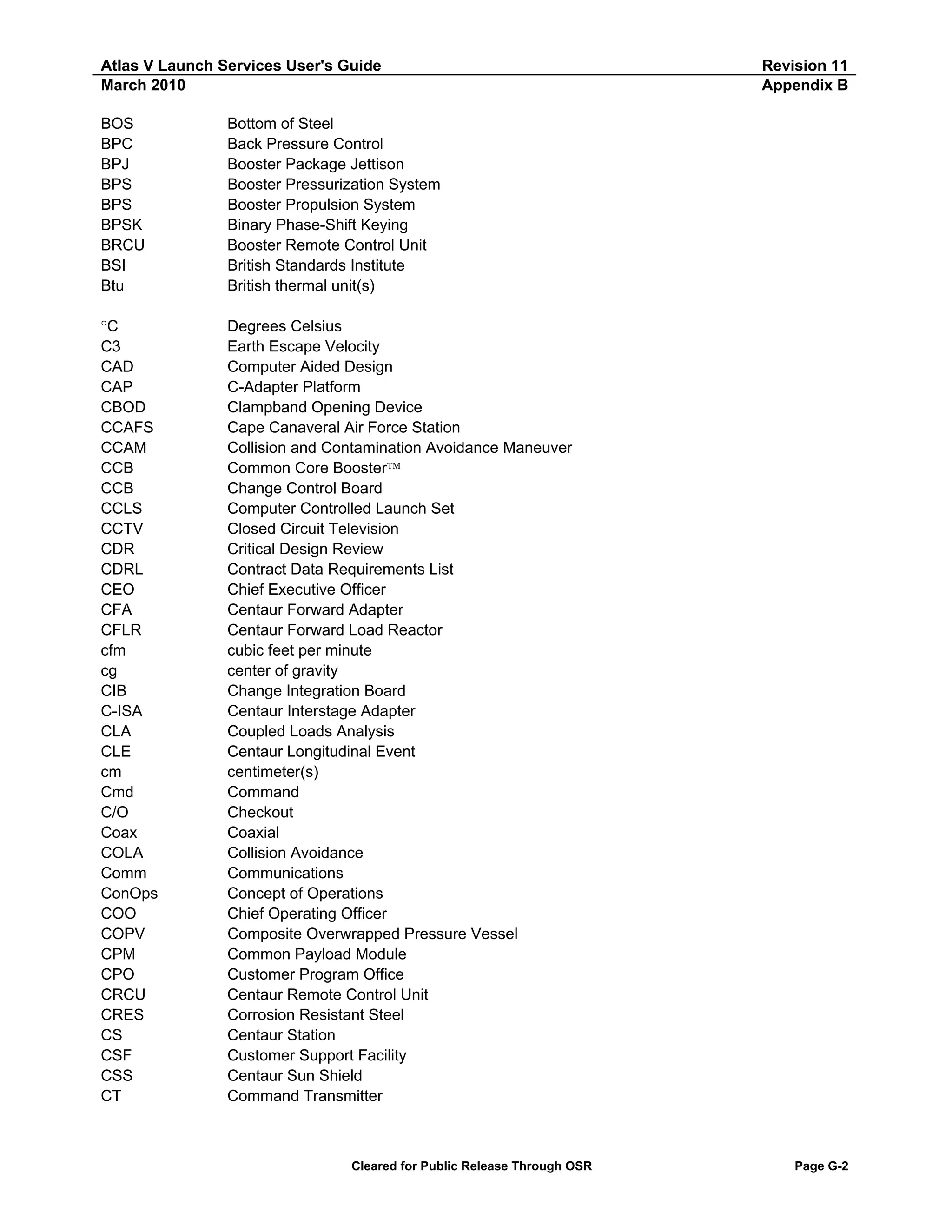

The document provides an Atlas V Launch Services User's Guide that includes essential technical and programmatic data for preliminary mission planning and spacecraft design. It describes the Atlas V launch vehicle family and capabilities, interfaces, environments, and facilities to allow assessment of first-order compatibility with customer requirements. The guide is periodically revised to reflect updates to vehicle performance and capabilities.


![Vibe Coding vs. Spec-Driven Development [Free Meetup]](https://cdn.slidesharecdn.com/ss_thumbnails/vibecodingvsspecdrivendevelopment-251209105622-43f455e7-thumbnail.jpg?width=640&height=640&fit=bounds)


