
Recommended
More Related Content
What's hot
What's hot (20)
Similar to ASM - Extruded Products
Similar to ASM - Extruded Products (20)
Recently uploaded
Recently uploaded (20)
ASM - Extruded Products
- 1. Extrusion: Second Edition Copyright © 2006 ASM International® M. Bauser, G. Sauer, K. Siegert, editors, p 9-58 All rights reserved. DOI:10.1361/exse2006p009 www.asminternational.org CHAPTER 2 Extruded Products Gunther Sauer* ¨ THE HOT-WORKING PROCESS extrusion main applications of extrusion. This process can is used to produce semifinished products in the also be used for certain copper alloys; however, form of bar, strip, and solid sections as well as the materials used for the extrusion tooling can- tubes and hollow sections. The high mean com- not withstand the thermo-mechanical stresses. pressive stresses in the deformation zone of the Billet-on-billet extrusion enables coiled tubes of container enable materials to be worked that long length to be produced, for example, alu- cannot be processed into semifinished products minum alloy heat exchanger tubes and tin and by other hot-working processes, for example lead alloy multicore solders. rolling, because of their limited workability. The The extrusion process generally produces a extrusion process also enables semifinished semifinished product close to the finished size products to be produced from powder metal- with materials with working temperatures up to lurgy-based materials, composite materials, and 600 ЊC. This occurs in one production step in the production of semifinished products from contrast to other processes used to form semifin- clad composites with material combinations in- ished products. Therefore, the design of the cluding aluminum/copper and aluminum/steel cross section of the semifinished product can using the cladding process. Finally, the sheath- practically ignore any limitations associated ing of electrical cables with lead or aluminum with subsequent processing operations. The alloys using the transverse extrusion process has most suitable cross-sectional geometry can be been a standard process for a long time, as has freely selected for the specific application. Sim- the production of multicore solders with inte- ple matching of the cross-sectional geometry of grated flux cores using the same process. the extrusion to the static, dynamic, and geo- The pushing of the material being extruded metric requirements combined with the wide through the shape-forming aperture of the extru- range of joining methods in assembly character- sion die enables cross-sectional shapes to be pro- ize the high functionality of the products pro- duced that cannot be manufactured by any other duced by this working process. hot-working process. The favorable deformation conditions with nonferrous metals such as tin and lead alloys as well as magnesium and alu- 2.1 Tin and Lead Extruded minum alloys with good welding properties and Products with a Deformation working temperatures that can be withstood by Temperature Range of 0 to 300 ЊC the tool materials also enable the billet to be di- vided into several metal streams, and then re- Tin alloy extruded products are mainly soft welded in the shape-forming region of the ex- solders with or without flux cores for use in elec- trusion die to form tubes and hollow sections. trical engineering and electronics. Tin alloys are The production of hollow sections is one of the significantly more common than are lead alloys. *Extruded Products from Materials with a Working Temperature Range of 600 to 1300 ЊC, Martin Bauser
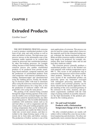
- 2. 10 / Extrusion, Second Edition They are produced on horizontal presses and The high density makes lead alloys particularly drawn, coiled, or wound to the customers’ de- suitable for radiation and noise protection. Good sired finished sizes on multispindle wire draw- workability combined with low melting points ing machines as shown in Fig. 2.1. The produc- means that lead alloys are also used for the man- tion processes are described in section 5.3. Other ufacture of soft solder, which is described in sec- extruded products are anodes used for electro- tion 5.3. Lead alloys, similar to tin alloys, are chemical plating with tin, for example, tin plat- also suitable for the production of custom ing for corrosion protection. Tin alloy extruded shaped anodes as shown in Fig. 2.2 for electro- products are also used in the manufacture of chemical plating. An example is the approxi- chemical equipment. mately 20 lm thick and soft running surface in Lead alloy products have lost a large part of plain bearings such as bearing shells and bushes. their market since World War II because of the Although the use of specific lead alloys for the toxic properties of these alloys. Even in the production of cable sheaths cannot be classified 1950s, extruded lead alloys were still used for as environmentally harmful, the cable industry water supply pipes up to the fittings on sinks. prefers alternative plastic and aluminum-base These materials were also used for extruded wa- materials. High-voltage cables are still sheathed ter waste pipes. This has changed completely. in lead. Spacers for double glazing (Fig. 2.3) are Lead alloys may no longer come into contact also extruded from lead alloys. Fishing nets and with food products because they can form very curtains are usually weighted with lead lines poisonous lead salts. Drinking water counts as a produced by horizontal extrusion. Some exam- food and, therefore, lead drinking water pipes ples are shown in Fig. 2.3. are no longer permitted. Nevertheless, lead al- Lead alloys can be made relatively resistant loys offer a range of advantages that make al- to corrosion by the addition of tin. They can also ternative materials difficult or even impossible be recycled relatively easily. However, the en- to find. Lead alloys have good resistance to vironmental political pressure will affect the cur- fluoric and sulfuric acids as well as phosphoric rent applications because of the toxic properties acid, ammonia, chlorine, and soda. They are of this material. therefore useful alloys for the chemical industry. Fig. 2.2 Extruded sections and tubes in lead base and tin al- Fig. 2.1 Soft solder with one or more flux cores (tube solder), loys for use as anodes for the electrochemical coat- extruded and drawn to the finished dimensions and ing, supply tubes for aggressive media, materials for seals and coiled on plastic spools. Source: Collin radiation protection, etc. Source: Collin
- 3. Chapter 2: Extruded Products / 11 pendent because of the hexagonal lattice struc- ture. In addition, any partial cold working of magnesium components, as is necessary, for ex- ample, for the aluminum alloy side door beam in Fig. 2.24, in the section “Passenger Cars,” is practically impossible because of this hexagonal lattice structure. Magnesium alloys naturally have good machining characteristics. Unlike aluminum alloys, they do not need any chip- breaking alloying additions such as lead and bis- muth. Consequently, extruded semifinished products are eminently suited to the production of turned components including ones in daily use, for example, pencil sharpeners. A typical profile can be seen in Fig. 2.4 [Fuc 96]. In the past, the market for extruded magnesium alloy products was limited in spite of the products’ good properties, in particular, their low density. The reason for this is both the lattice-related poor cold-working properties, and the hot-work- ing properties that are very alloy dependent. The Fig. 2.3 Extruded solder with several flux cores, lead main application for magnesium alloys is, there- sheathed cable, and window spacer sections in lead alloys for double glazed windows, as well as lead lines for fishing fore, still cast components. The most well- nets and curtain weights. Source: Collin known application is the engine and gearbox housing used after World War II in the air-cooled flat twin engine in the Volkswagen Beetle. 2.2 Magnesium and Aluminum Basically, magnesium products are used Extruded Products with a Working where the weight saving, e.g., components with Temperature Range of a low mass, has high priority. The main areas of 300 to 600 ЊC application are automobile and machine manu- facture. The extruded products shown in Fig. 2.5 and 2.6 are suited primarily for machine com- 2.2.1 Magnesium Alloy Extruded Products ponents subjected to high acceleration and brak- Magnesium alloys are light materials with ing, for example, in textile machine components useful mechanical properties. Their density of [Fuc 96]. These products are also used in the approximately 0.0018 kg/m3 is about 36% less aerospace industry and in military applications. than that of the aluminum alloys. The Young’s modulus (E) is approximately 45 GPa and, therefore, about 65% of the E-modulus of alu- minum alloys. For this reason, they are, in prin- ciple, more interesting than aluminum alloys as a construction material for light components. However, the corrosion resistance of magnesium components is not usually as good as that of alu- minum components. They, therefore, have to be given more surface protection. The corrosion sensitivity of magnesium alloys can be lowered significantly by reducing the trace element con- tent of copper, iron, manganese, and nickel into the ppm region. The corrosion behavior of high- purity magnesium alloys approaches that of alu- minum alloys. This has considerably increased the interest in magnesium alloys as construction Fig. 2.4 From left to right: Section in MgAl2Zn for the pro- duction of pencil sharpeners, two sections in materials. However, the mechanical behavior of MgAl3Zn for warp knitting machine, and test arm sections for magnesium components is very directional de- disc magazines. Source: Fuchs-Metallwerke
- 4. 12 / Extrusion, Second Edition truded products were used to a significant degree in the period before World War II. Complete fu- selages in hot-rolled and section-reinforced magnesium sheets were produced for small air- craft [Bec 39]. Bus trailers were manufactured almost entirely from hot-worked magnesium al- loys, including a welded frame of extruded mag- nesium tubes clad with magnesium sheet [Bec 39]. Welded seat frames for passenger aircraft were made from extruded magnesium tubes. The increasing interest by the automobile in- dustry in light extruded products in order to save energy by reducing vehicle weight has resulted in increasing examination of extruded semifin- ished products in magnesium alloys. This will gain in importance if the further development of the magnesium alloys results in higher values of static and dynamic strength and improved work- ing and corrosion properties. It can, therefore, be assumed that magnesium alloys will also be used to an increasing extent for load-carrying components as well as safety components, which require a good proof stress and elonga- Fig. 2.5 Extruded section in MgAl3Zn for textile machines. tion. Magnesium alloys are, moreover, as easily Source: Fuchs-Metallwerke recycled as aluminum alloys. The extrusion of magnesium alloys is de- scribed in section 5.5. 2.2.2 Aluminum Alloy Extruded Products The main application of the hot-working pro- cess extrusion is in the general production of bars, tubes, and wire in aluminum alloys and, in particular, the manufacture of aluminum sec- tions. No other material is used as a semifinished product to the same extent in practically all areas of technology. Acceptable materials properties and modulus of elasticity, weight saving from the low-density, good surface quality, good di- mensional accuracy and minimum subsequent machining, and ease of recycling make alumi- Fig. 2.6 Hollow section in MgAl3Zn for the external rotor of a turbocharger for automobile engines. Source: num alloys both economically and environmen- Fuchs-Metallwerke tally interesting. These properties, as well as the largely unrestricted shape of the cross-section geometry, are the basis for the trend to the de- Magnesium alloys are being developed fur- velopment of ever more functional components ther because of their suitability for light com- with good appearance and corrosion resistance. ponents with the intention of achieving higher The reason for the predominance of alumi- static and dynamic mechanical properties as well num profiles in extrusion is due to the moderate as improving the working properties [Tec 96/97/ working temperatures of the aluminum alloys. 98, Gar 93]. Interest in magnesium alloy com- The extrusion tooling can then withstand the ponents is increasing, particularly in the auto- thermo-mechanical stresses. In general, the mobile industry. working temperature of aluminum alloys is be- In the past, hot-worked semifinished products low the annealing temperature of the hot-work- in the form of magnesium alloy sheet and ex- ing tool steels normally used to manufacture alu-
- 5. Chapter 2: Extruded Products / 13 minum extrusion tools. This has played a same round container by using spreader tech- decisive role in the development of the design niques. West European aluminum extrusion of extrusion tooling for aluminum profiles. Very plants today can produce extruded sections rang- demanding aluminum profiles can now be pro- ing from 10 g/m to 130 kg/m. The section “Ex- duced. In recent years, the development of ex- trusion of Semifinished Products in Aluminum trusion tools for the production of large profiles Alloys” describes the extrusion processes used has been particularly successful. today for aluminum alloys. Large profiles are used today in almost all ar- The large profile technology was first devel- eas of industry. In Europe alone there are four oped in the second half of the 1970s for the con- large extrusion presses with press powers of struction of railway rolling stock. Until then, the 72,000 to 100,000 kN used to produce them. technical advantages of aluminum aroused some Standard solid and standard hollow sections interest in its use as a construction material, but with a circumscribing circle diameter of approx- the classic method of construction of railcar imately 600 mm can be produced from 650 mm body shells using sheet and small extruded pro- round containers on the 98,000 kN direct extru- files could not compete with the proven con- sion press operated by Alusuisse in Singen (Ger- struction material steel. A light steel design of many) (Fig. 2.7). Solid flat sections with maxi- the body shells was about 50% cheaper than a mum dimensions of 800 by 100 mm (width by comparable one made from aluminum alloys. height) and flat hollow sections with a maximum The light steel construction was, therefore, pre- size of 800 by 60 mm can be produced from the ferred. This changed with the introduction of Fig. 2.7 Large sections produced from containers with a circular bore on the 98,000 kN direct extrusion press in Singen. Adapted from Alusuisse
- 6. 14 / Extrusion, Second Edition large profiles the length of the rolling stock that a higher alloy content) do not offer the same could be automatically welded to each other. profile geometry options as the low alloyed The assembly cost of the railcar body shells and easily welded aluminum alloys such as could be reduced to an extent that not only com- AlMgSi0.5 and AlMgSi0.7. pensated for the higher material cost of the alu- Figure 2.9 shows a body shell of the Paris minum but also reduced the total cost of the alu- Metro type MF 77 utilizing welded large profile minum wagon by approximately 30% of that of technology. The carriage cross section is shown the steel wagon [Wis 92, Cor 95]. in Fig. 2.8, together with some of the large pro- Aluminum designs using large profiles that files necessary for its construction. Figure 2.10 simplified assembly then started to compete with shows the right longitudinal rib needed to stiffen steel. Today, aluminum large profile technology the floor frame of the carriage of the San Fran- has become the economic solution in many cisco Metro in the alloy AlMgSi0.7 on the run- branches of technology. Large profiles enable out table of the 98,000 kN direct press in Singen, several fabricated classic components to be re- Germany. placed. Extruded profiles can be supplied as in- Since the introduction of the integral con- tegral components ready for installation. Large struction utilizing large section technology, alu- profiles not only can replace several classic com- minum designs can increasingly compete with ponents but also, in addition to their static and steel designs in spite of the higher material cost dynamic functions, take on additional functions of the aluminum. The specific properties of alu- in addition to the overall function with the min- minum alloys play a role here including the low imum of additional material as shown in Fig 2.8, E-modulus of the various alloys and their low which depicts cross-sectional views of a carriage density. Whereas the E-modulus of aluminum of the Paris Metro [Alz 85]. alloys can be assumed to be approximately 70 The mechanical properties of the aluminum GPa, that of steel is approximately 210 GPa, alloys used for the production of large aluminum three times as high. At the same time, the alu- profiles are adequate for most applications minum designs can be given the same stiffness where good design enables the profile geometry as steel designs to avoid unacceptable bending to be adequately dimensioned. Nevertheless, dif- or vibrations with significantly lower weights ficult to extrude and, to some extent, moderately because of the low density of 2.7 g/cm3. In ad- difficult to extrude aluminum alloys (those with dition, the elastic properties of aluminum de- Fig. 2.8 Shell of a type MF77 carriage of the Paris Metro, self-supporting in welded large section technology (Alsthom Atlantique/ Alusuisse, 1977/1981) manufactured in sections from the age-hardened material AlMgSi0.7. a, Multifunctional longitudinal stringer; b, construction of the carriage body in the roof longitudinal stringer region; c, weld joint geometry between the individual extruded sections; 1, multifunctional longitudinal stringer; 2, section in roof region with extruded weld preparations; 3, longitudinal stringer to ensure adequate stiffness of the floor group; 4, door mechanism; 5, rainwater gutter extruded on section 1; 6, door seal location extruded on section 1; 7, roof closure section; 8, roof internal cladding; 9, floor section with extruded legs for the welded joints as well as extruded center locations; 10, floor group sections with extruded slip seating for tolerance equalization; 11, section view of the floor sections with extruded locations for bolt heads. Source: Aluminium Zentrale
- 7. Chapter 2: Extruded Products / 15 signs offer significant advantages. Aluminum al- one of the largest North American Railway com- loys have significantly higher elastic or energy panies, had built for them, excluding the con- absorption capacity relative to steel because of ventional locomotive design, an aluminum ex- their low E-modulus. This is an advantage that ample of the semistreamlined steam-powered should not be undervalued for aluminum designs “Royal Blue,” traveling between Chicago and subjected to impact loads, for example, in rail or St. Louis [Hug 44]. Only the wheel trucks, cou- road transport vehicles. plings, and buffers of the eight passenger cars were made in steel, all other components from alloys of the alloy group AlCuMg. Long ex- 2.2.2.1 Transport Construction truded profiles were used for the load-carrying Rolling Stock. Efficient low-weight rolling components of the car underframe. Even the col- stock has always been of interest to railway op- umns of the side walls were made of extruded erators. Low weights provide higher load capac- profiles, which were also used for the necessary ities with lower energy consumption and enable stiffening in other places in the carriage. Formed higher vehicle accelerations when starting and sheets in the same aluminum alloy were used for higher vehicle deceleration on braking, as well the cladding of the carriage walls, for the train as a reduction in rail wear. These advantages are car roof as well as for the floor. mainly utilized by local traffic with its many Sections and sheet were joined together with stops, e.g., underground trains, but also by long rivets and arc welding. In addition, the internal distance traffic, in particular, high speed rail fittings of the carriage, for example, the tables traffic. and seats in the dining car, also were made from Toward the end of the 1920s, the transfor- aluminum alloys. The eight carriages built com- pletely from aluminum had a total weight of 350 mation of weight reduction in rolling stock re- metric tons in contrast to the identically con- sulted in the replacement of steel internal fittings structed steel carriages with 650 metric tons, i.e., by fittings made in aluminum alloys, initially in 54% of the weight of the steel carriages. passenger carriages. However, in 1934, the Bal- timore and Ohio Railroad Company, at that time Fig. 2.10 Large section in the aluminum alloy AlMgSi0.7 for Fig. 2.9 Assembly of an aluminum MF77 type shell for the aluminum carriages for the San Francisco Metro Paris Metro using welded large section technology using large section welded technology on the runout table of the together with some large sections ready for assembly. Source: 98,000 kN direct extrusion press at Alusuisse Singen. Source: Alusuisse Alusuisse
- 8. 16 / Extrusion, Second Edition Fig. 2.11 Diesel power car of the Trans Europa Express (TEE) on the Rhine section The desire to reduce the weight of rolling stock by using aluminum alloys continued to de- velop after World War II. In the second half of the 1950s, the German Rail Company operated several of the advanced for the time fast diesel locomotives designated VT 11.5 with a maxi- mum speed of 160 km/h for the lucrative long- distance service. The carriages were made from riveted and spot-welded AlMgSi1 sheets with longitudinal and transverse stiffeners in extruded solid AlMgSi1 sections. Both types of semifinished products were used in the age-hardened temper. Only the main transoms in the under frame of the carriage as well as the wheel trucks and cou- pling carriers were made in St52 steel as well as the coupling system. Figure 2.11 shows this Fig. 2.12 Carriage body of the Trans Europa Express (TEE) in diesel train on the Rhine section, and Fig. 2.12 riveted and spot-welded ALMgSi sheets with lon- gitudinal and transverse stiffeners in extruded sections of the shows a cross section of the conventionally built same alloy in the heat treated temper and thus correspondingly expensive carriage. The multiunit railcar train shown in the pho- tographs with its design that is still modern by today’s standards traveled as the Trans Europa Express (TEE) in Inter-European long-distance for train speeds up to 200 km/h, speeds that travel. It consisted of five carriages as well as could be achieved using electric locomotives. In the two power cars, each with a diesel engine, the context of the further technical development at the front and the back. The basic concept of of the wheel/rail system, the tracks have been this diesel multiunit railcar, two external power prepared in the past 10–15 years for significantly cars with the carriages in between, is practically higher speeds. In the near future, the European the basis of the German InterCity Express trains railways are targeting future high-speed rail traf- ICE1 and ICE2 used today. fic with speeds of 350 km/h (220 mph). Large During the postwar decades, the European na- advances along this path have been made by the tional railways built their rail networks initially French national railway SNCF with its TGV,
- 9. Chapter 2: Extruded Products / 17 which set a world record of 515 km/h (320 mph) Ing 91]. Further development resulted in interest on test runs. In the next 20 years in Europe, a in the aluminum large profile technology for the certified rail network for high-speed trains with multiunit railcars for the high-speed rail traffic. multiple current systems and corresponding sig- In this period, the percentage of rolling stock nal and control systems will develop in Europe produced using large aluminum alloy profile to allow inter-European long-distance trains to technology increased out of proportion. At the travel the national rail networks. These stretches start of the 1970s, it was approximately 5% but are operated for inter-European long-distance has now increased to over 60% [Ing 91]. train travel with train concepts that do not follow Whereas the French high-speed train TGV of the previously conventional train system of “a the SNCF with its respectable power and proven locomotive with carriages.” One example is the ability over several years was manufactured in Eurostar, a special design of the TGV with a steel, the German Railway decided to build its multiple current system that can travel between 280 km/h (175 mph) high-speed trains InterCity Paris and London in three hours through the Express 1 (ICE1) and InterCity Express 2 (ICE2), Channel Tunnel. The ICE3 of the DB follows a as well as the 330 km/h InterCity Express 3 similar concept. (ICE3), and the 230 km/h InterCity Express T From this perspective, the European railway (ICET), basically using self-supporting welded operators have a vital interest in trains with the large aluminum profile technology. The only ex- lowest possible weight for the high-speed rail ception was the power cars of the trains ICE1 network as described previously. Low weights and ICE2, which were manufactured in steel to minimize the energy requirements for powering ensure that the driven four axles per power car these trains as well as the wear of the tracks and could apply sufficient normal force onto the permit high accelerations when starting and de- track to obtain the torque needed to achieve high celerations on braking. acceleration and deceleration. The big breakthrough for the economical ap- This, however, results in high track loading plication of aluminum alloys in carriage con- because each wheel truck of these power cars struction was the development of the large pro- places a load of 40 metric tons onto the rails. file technology in the 1970s by Alusuisse. This Throughout Europe, however, the track can only enabled rolling stock to be entirely and eco- be loaded to a maximum of 34 metric tons per nomically produced from aluminum at a signifi- wheel truck. For this reason, the two high-speed cantly lower cost than comparable rolling stock trains ICE1 and ICE2 cannot use the inter-Eu- in steel lightweight construction. This involves ropean rail network. This, however, changed the use of easily extruded, relatively corrosion with the introduction of the high-speed train insensitive, and easily age-hardened aluminum ICE3, which in contrast to the power car train is alloys such as AlMgSi0.5 and AlMgSi0.7, with- designed as a multiunit train; i.e., the driven out which the very demanding cross-sectional axles are spread along the entire train with every geometries of the large profiles could not be pro- second axis being driven. These trains apply a duced. These extrusion alloys also provided sig- load less than 34 metric tons weight on the track nificant freedom in the design of the cross sec- per wheel truck and are therefore suitable for tion to match the strength needed in the participation as multisystem trains for the Inter- component. Until now, this could not be European traffic [Tas 93]. The InterCity Express achieved with moderate to difficult to extrude T (ICET) is in certain ways a special design of alloys used previously in the manufacture of the ICE3 fitted with tilting technology devel- rolling stock. Modern concepts were also devel- oped in Italy. With this design, the multiunit oped for the steel lightweight designs of rolling train can travel around curved rails with high stock, but these could not significantly reduce speed. Figure 2.13 shows an example of the the price advantage of the aluminum large pro- ICE1 framed with a schematic diagram of the file technology [Aug 77, Wis 92]. The rolling extruded profiles for the floor group, the longi- stock produced from welded large profile tech- tudinal member of the floor group, and the con- nology also offers weight advantages over those necting edge wall profile of the left side of the produced from the high-strength steels. Both passenger carriage. The joint aids visible on the these factors resulted in the extensive applica- section corners in Fig. 2.13 for the longitudinal tion of the aluminum lightweight construction joining of the extruded sections are of interest. incorporating the large profile technology in Eu- Finally, Fig. 2.14 describes the design of the rope and the United States in the 1980s [Dav 79, passenger carriage with all the large profiles for
- 10. 18 / Extrusion, Second Edition Fig. 2.13 High-speed ICE1 of the Deutsche Bahn AG framed by the large sections of the carriage cross section shown in Fig. 2.14. Source: Alusuisse the left half of the carriage. In addition, Fig. 2.15 the aim of reducing transport energy costs. For shows a view of the design of the passenger car- a long time, there has been increasingly rigorous riage of the high-speed trains ICE2 and ICE3. competition with other methods of transport, in- Other European national railways, for exam- cluding road transport. Initially, this involved in- ple, Denmark, England, Italy, and Norway, as creasing the load capacity of the freight wagon well as Spain and Sweden, have learned the by using individual, usually movable, aluminum value of the self-supporting aluminum large pro- alloy components for the same wagon axle load. file technology in welded designs for high-speed Consideration was then given to significantly trains as well as intercity passenger carriages improving the handling of the construction ele- and intercity rail cars. This technology has, for ments. Sliding roofs, folding roofs, as well as example, been used for building the 250 km/h sliding doors and shutters, were manufactured (155 mph) high-speed Advanced Passenger from aluminum sheet and reinforced with ex- Train of British Rail and the 300 km/h (185 truded sections by the German railway, DB, as mph) ERT 500 of the Italien Ferrovie dello Stato well as the Swiss Federal Railway, SBB. With (FS). The French TGV Duplex, a double decker, time, complete wagon bodies also were built new high-speed train of the SNCF, will be man- from aluminum alloys. The structure of these ufactured using welded aluminum large profile wagons consisted of roll formed 1.5 to 2.0 mm technology to control the track loading. thick AlMg3 sheets reinforced with AlMgSi0.5 Self-supporting large profile aluminum tech- extruded sections, apart from the under frame nology is used not only for high-speed trains and the vertical end wall columns, which were running on rails. The carriages of the track made in steel. In addition, the aluminum con- guided fast magnetic levitation Transrapid, with struction offers not only the advantage of weight a maximum speed of 500 km/h (310 mph) are reduction but is also maintenance friendly, i.e., built using the self-supporting aluminum large in contrast to steel designs, no painting is needed profile technology in a bolted design [Mil 88]. because of the corrosion resistance of the alu- The prototype is shown in Fig. 2.16. This assem- minum alloys used. bly method is described in the section “Bus Tilting sidewalls on open goods wagons for Manufacture” later in this chapter. specific transport applications are manufactured Naturally, thought has been given to reducing from AlMgSi0.5 and AlMgSi0.7 extruded pro- the wagon weight in rail freight transport with files, as shown in Fig. 2.17. These sidewalls can
- 11. Chapter 2: Extruded Products / 19 Fig. 2.14 Passenger carrier design on the high-speed train ICE1 of the Deutsche Bahn AG with the large sections of the left carriage section. Source: Alusuisse be highly loaded and do not require any surface large distances. This process is usually carried protection because of the corrosion resistance of out using rolling stock with the optimum load the aluminum alloys. capacity. The optimum storage capacity of these The focal point of European rail transport is wagons can be achieved by using self-support- mixed cargo transport where the loading space ing welded aluminum large profile technology, of a wagon is more important than the load- which makes them particularly economical carrying capacity. Consequently, the application compared with wagon designs in steel. Figures of aluminum alloys is usually limited to movable 2.18 and 2.19 show an example of a coal silo components as described previously. Bulk goods wagon built with aluminum large profile tech- transport by rail has only a limited role in Eu- nology. The sidewalls as well as the chassis of rope. this coal silo wagon consist mainly of large This differs in other countries, including extruded profiles in the aluminum alloy Australia, Canada, South Africa, and the United AlMgSi0.7 with large format sheets of States, with, for example, rich surface reserves AlMg2.7Mn in the floor area. The assembly of of coal and minerals. The extraction site is usu- the silo wagon involves the use of the same ally a long distance from the processing plant automatic welding systems that are used for so that bulk goods have to be transported over personnel carriages.
- 12. 20 / Extrusion, Second Edition Silo wagons of this design were designed and load is approximately 10% less than that of a built by Alusuisse to U.S. standards. In spite of steel wagon. the high material costs of the aluminum silo Road Vehicles. The development of auto- wagons, their manufacturing cost per ton pay- mobile manufacture including both cars and Fig. 2.15 (a) Carriage shell cross section ICE2 and (b) carriage shell cross section ICE3, self-supporting using welded large section technology. Source: ADtranz Fig. 2.16 Prototype of the magnetic levitation Transrapid manufactured with bolted aluminium large profile technology using aluminium AlMgSi0.7 extruded sections. Source: Alusuisse
- 13. Chapter 2: Extruded Products / 21 Fig. 2.17 Tilting trailer walls of an open goods wagon finished in extruded hollow sections in the alloys AlMgSi0.5 and AlMgSi0.7. Source: Alusuisse Fig. 2.18 Coal silo wagon produced in welded self-supporting large extrusion technology to U.S. standard. Source: Alusuisse freight vehicles has been associated with the use After World War II, this development in- of aluminum alloys from the beginning. Alu- creased rapidly. The use of aluminum alloys in minum gearbox and motor housings were al- road vehicles increased continuously. Today, af- ready being reported in the latter years of the ter steel, aluminum alloys are the most important nineteenth century. In 1924, the Swabische Hut-¨ material in the manufacture of automobiles. In tenwerk developed a car with a self-supporting 1993, in Germany alone 315,000 metric tons of aluminum design. In 1937, BMW fitted the well- aluminum were used in the manufacture of cars known two-seater sports car 328 with an alu- and 58,000 metric tons in freight vehicles [Gor minum alloy body. In racing car manufacture, 94]. The main applications of aluminum are the well-known Silver Arrow manufacturer castings for engine and gearbox housings, pis- Auto Union, BMW, and Mercedes Benz used tons, and cylinder heads, as well as car wheels. aluminum alloys to produce the lightest chassis It is also used as a semifinished product in the possible. Toward the end of 1920s, the first form of sheets or strip for the manufacture of buses with aluminum bodies were built, particu- bonnets and boot lids, water and oil coolers, and larly in Switzerland (Fig. 2.20). also sometimes for complete sports cars bodies
- 14. 22 / Extrusion, Second Edition Fig. 2.19 Design and construction of the coal silo wagon shown in Fig. 2.18 Fig. 2.20 Older bus body manufactured from aluminum alloys in Switzerland with a frame in extruded sections. Source: Alusuisse as well as extruded semifinished profiles for the consumption by about 0.6 to 0.8 l/km (in- production of trim and widow frames, and for creases mileage 3.5 to 4.7 mpg). safety components such as side-impact beams in ● Lower environmental pollution from exhaust car doors. Car superstructures and bus bodies, gases as a result of the reduced fuel con- goods vehicle superstructures, and sidewalls, in sumption. addition to forgings for the manufacture of ● Reduction in maintenance costs due to the wheels and engine components, are also made better corrosion resistance of the aluminum from aluminum. This increasing use of alumi- alloys num alloys provides these well-known advan- ● Simple recycling of the aluminum alloys tages to the automobile industry: used as secondary aluminum ● Lower vehicle mass and thus savings in mo- Passenger Cars. In 1958, Opel in Germany tive energy, i.e., fuel. According to [Her 90], introduced the Rekord shown in Fig. 2.21 as a the replacement of 200 kg of steel by 100 kg new design to the market. The car had as a new of aluminum in a car reduces the gasoline feature for the European automobile industry
- 15. Chapter 2: Extruded Products / 23 window frames in extruded and age-hardened years, high demands were placed on the deco- aluminum alloy for the front and rear wind- rative appearance, in particular, on the optimum screens, as well as the side windows in the doors. polish. Good mechanical properties were also The aluminum frames were attached in such a required. The top of the door consisted only of way to the steel sheet that the top of the door an aluminum frame, and this frame should not consisted only of the window frames with the bend when the door was closed. Aluminum ex- window glass, as shown in Fig. 2.21. The ex- truded profile window frames appeared in many truded profiles that formed the frames were de- car models for over a decade. During this period, signed in such a way that the rubber sections that between 150,000 and 200,000 metric tons alu- sealed against the body could be easily located minum sections flowed into this project. Car in the aluminum window frames. The extruded manufacturers finally stopped using this deco- profiles were formed to the window frames on rative aluminum window frame construction on stretch bending machines, welded together, the doors mainly because of the wind noise be- ground, and polished and anodized to a thick- tween the window frame and the body associ- ness of 4 to 6 lm. The section material used by ated with the rapidly increasing speeds. The Opel was initially Al99.8ZnMg and, later, cause of the wind noise was the speed-related Al99.8MgSi. suction forces acting externally on the window Opel introduced this design within Germany surfaces and also the pressure forces from the following pressure from the United States. The operation of internal fans on the inside of the design was quickly adopted by Audi, BMW, and window surfaces. This revealed a weakness in Ford. The aluminum alloy solution heat treated the aluminum window frame design. As a con- during the billet heating was extruded into water sequence of the E-modulus of the aluminum al- (standing wave). The sections had a weight per loys used for the window frames being one-third meter of only 0.150 to 0.850 kg. In the early that of a suitable steel, the aluminum window frames deformed elastically three times as much as a steel frame of the same design. Profile cross sections with higher moments of inertia could not easily be incorporated into the door design. This did not exclude, however, the further use of extruded profiles as frames for the front and rear car windscreens, as shown, for example, in the E class Mercedes in Fig. 2.22. In addition, Fig. 2.22 Rear window frame of the Mercedes W124 man- Fig. 2.21 Automobile window frame in extruded, age-hard- ufactured from extruded aluminum sections. The ened, and anodized aluminum sections on an front windshield of the vehicle had a similar frame. Source: Erbs- Opel Rekord manufactured in 1958. Source: Opel loh ¨
- 16. 24 / Extrusion, Second Edition numerous extruded profiles are used in car bod- cross-sectional geometry and sufficient proof ies for a wide range of applications, including stress and elongation are particularly suitable for steering wheel adjustment, seat rails, sliding roof this application [Fra 89]. A correctly designed guides, and also for water and wind deflectors impact beam in an extruded aluminum alloy in the roof area of the body and side window with materials properties comparable to a geo- guides. Figure 2.23 depicts the metal frame for metrically similar steel impact beam can possess the folding top cover of the SL class made from approximately three times the elastic deforma- an extruded profile. tion capability before plastic deformation oc- Aluminum extruded profiles are particularly curs. suited in special cases for the manufacture of Interest in the extruded age-hardened alumi- safety components for the automobile because num alloy side-impact beam combined with a the cross-sectional shape can be exactly matched to the loading. They also offer favorable me- chanical properties and density and the low E- modulus as well. A typical example is the side door beam that can fulfill its role in a very func- tional way. Side impact causes 30% of all road deaths in 25% of all car accidents in Germany. The car sides cannot be protected for space rea- sons by crumple zones as, for example, used in the front and rear. Therefore, the car manufac- turers have over the years made great efforts to protect the sides of cars using effective side- impact beams as well as air bags. Figures 2.24, 2.25, and 2.28 show this technology in Audi ve- hicles. The impact beam must be able to absorb the transmitted impact energy from an impact on the side door over a defined deformation displace- ment without breaking, buckling, or even dis- placement in order to protect the passengers. Re- search results have shown that extruded aluminum alloy profiles with a symmetrical Fig. 2.24 Side door of the Audi 100 with built-in chroma- tized for corrosion protection, extruded section in the aluminum alloy AlMgSi1, F 31 with RP0.2 062 סN/mm2 and A5 .%01 סSource: Alusuisse Fig. 2.25 Side-impact beam from the Audi 8 consisting of Fig. 2.23 Hood container cover of the Mercedes 300 SL and two extruded sections. Alloy AlMgSil, F 31. The 500 SL class with extruded aluminum section side-impact beam can be seen installed in Fig. 2.27. Source: Alu- frames. Source: Erbsloh ¨ suisse
- 17. Chapter 2: Extruded Products / 25 side air bag is increasing because the good However, in cars this did lead to weight reduc- physical and mechanical properties, in particu- tions of about 60 kg in Europe and about 80 kg lar, the elastic behavior, enable the safety re- in the United States. The desire for larger weight quirements to be fulfilled. Many automobile savings now has resulted in greater use of light manufacturers are now installing them. materials. In the future, engine and gearbox Naturally, there are numerous safety compo- housings will be made primarily from aluminum nents that are manufactured from extruded alu- alloys. Car manufacturers are also replacing minum profiles. Figure 2.26 shows a steering load-carrying steel automobile components with linkage in which the left-hand link consists of aluminum. This gives an additional weight sav- sections of extruded profiles, whereas the flexi- ings of 60 to 70 kg and a definite improvement ble right-hand part is manufactured from impact in the ride because of the significantly lower un- extruded tube sections with formed bellows. In damped weights. an accident, the bellows deform so that the im- Meanwhile, the automobile driver has be- pact on the steering column is reduced. The come increasingly more demanding. The stabil- good experience obtained with the deformation ity of the body, the airbag, and the side-impact behavior of side-impact beams made from ex- beams, ABS and effective crumple zones pro- truded age-hardened aluminum hollow sections vide passenger protection. In addition, air con- has now been used in automobile plastic bumper ditioning, CD systems, navigation systems, and beams with integrated aluminum hollow sec- other luxurious fittings should make traveling in tions in the alloy AlMgSi0.5 or AlMgSi0.7. a car as pleasant as possible. Simultaneously, the These sections naturally have to match the pro- fuel consumption should decrease and the ma- file of the bumper beam, i.e., they have to be terials from old vehicles be easily recycled. bent. Whereas this bending operation is carried In the future, these conflicting demands will out today on a large scale on stretched extruded be met by the use of light body designs in steel, profiles with significant cost for the bending, de- aluminum alloys, improved magnesium alloys, pending on the section geometry, possibly fol- and to a limited extent by fiber-reinforced plas- lowed by a sizing operation, these deformation tic, if necessary, up to self-supporting structures. processes can be carried out in the United States As early as 1950, Pakiney built the DYNA during the extrusion process. The low hot flow PANHARD car with extensive use of AlMg3 stress of the aluminum alloy aids the bending sheet and, later, AlMgCu. The car weighed only process. The introduction of defined and legally re- 650 kg and was extremely economical. In 1990, quired targets of weight saving, energy saving, Honda developed the sports car NSX with and simple recycling of the materials used has AlMgSi1 sheet, and Rover has used for many initiated significant innovations in recent years years in the Land Rover aluminum sheets for the in the automobile industry. Previously, alumi- body; initially, AlMgCu and, today, AlMgSi1 num alloys were generally used for simple parts. [Alp 94]. The decisive step was made by AUDI AG with the production of the AUDI A8 shown in Fig 2.27. The body is made entirely of alu- minum. This breakthrough of aluminum into the steel domain has both shocked and challenged the wide strip manufacturers (body sheet). They are trying to counter this development with intelli- gent solutions for complete steel chassis, for ex- ample, with the use of prefinished body parts, tailored blanks. Tailored blanks are cut to size, designed for the load, body panels laser welded together from steel sheets of different thickness, strength, and surface quality. These prefinished Fig. 2.26 Steering link in the alloy AlMgSi1, F 31. The con- body parts, for example, complete wheel hous- nection on the left-hand side is from an extruded section, whereas the round, easily deformed in the event of a ings, enable assembly costs and also weight to crash, corrugated section with the transition to the steering col- be reduced. This is the start of a process that umn was manufactured from an extruded tube. The corrugated region is heat treated to a strength of F 22 to F 25. Source: Alu- should finish with the ultralight steel car body. suisse However, the high point of this development to-
- 18. 26 / Extrusion, Second Edition day is the Audi A8 and the Audi A2 with the the age-hardening alloys AlMgSi0.5 and space frame construction of Alcoa. This con- AlMgSi0.7. Supporting floor panels consist of struction principle can be seen in Fig. 2.27 to the age-hardening alloy AlMgSi1Cu, small 2.29. Audi uses for the production of the alu- sheet parts from the non-heat-treatable alloy minum body aluminum alloys containing the AlMg5Mn. The die cast nodes necessary for same alloying elements, a basic requirement for joining the preformed and age-hardened ex- ease of recycling. The extruded sections needed truded profiles to balance out the tolerances for to assemble the space frame are produced in the space frame of the Audi A8 were manufac- Fig. 2.27 Audi A8 Quatro with a body of age-hardened aluminum alloys using the Alcoa space frame concept. Source: Audi Fig. 2.28 Space frame of the Audi A8 shown in Fig. 2.27
- 19. Chapter 2: Extruded Products / 27 Fig. 2.29 Space frame of the Audi A2 in extruded sections, sheet and castings. Source: Audi tured with the vacuum casting process in the els that harden during this heat treatment. The heat-treatable alloy AlSi10Mg. Other cast com- sections of the space frame heat more slowly ponents consisted of AlSi7. Die cast components because these are shielded by the body outer for tolerance compensation were not used for the skin during the heat treatment. For this reason, space frame of the A2. the bent profile sections for the space frame have Finally, cold-worked strip sections in the flow to be supplied age-hardened in such a way that line free (Luders lines) and heat-treatable alu- ¨ they harden only slightly during the age-hard- minum alloy AlMg0.4Si1.2 were used as exte- ening process described and do not over age. In rior body panels. Table 2.1 provides an overview particular, the softened peripheral zones of the of the materials used to build the aluminum body section welded from the MIG welding should as of the Audi A8. far as possible reharden. The complete alumi- The automobile manufacturer joins the deliv- num body of the Audi A8 is approximately 200 ered prefinished and age-hardened profile sec- kg lighter than a conventional steel body of the tions to assemblies by MIG welding with the aid same size. of jigs. The complete space frame is then built Bus Manufacture. The manufacture of buses using the same joining technique. The floor pan- from aluminum alloys has a tradition in Swit- els and, in particular, the 1.0 to 1.15 mm thick zerland, as shown in Fig. 2.20. The Alpine coun- sheets for the body exterior skin were fixed us- try started to consider the reduction in weight of ing other joining techniques including, among goods vehicles in the 1920s. The engine powers others, self-piercing rivets. Finally, the finished available at this time were still very limited and body in white is age-hardened at a temperature could therefore be better utilized with a lower of 230 ЊC for 30 min. It is mainly the body pan- weight. The Swiss with their mountainous re- Table 2.1 Aluminum alloys used for the aluminum body of the Audi A8 Material AA(a) Temper Rp0.2 (N/mm2)(b) Rm N/mm2(c) A5 %(d) Sheet AlMg0.4Si1.2 6016 T6 200 250 14 AlMgSi1Cu 6009 T6 230 280 10 AlMg5Mn 5182 ... 135 270 25 Vacuum die casting AlSi10Mg ... T6 120–150 180 15 Permanent mold casting AlSi7 ... T6 200 230–250 15 Extruded section AlMgSi0.5/0.7 ... T6 210–245 1.08 Rp0.2 11 (a) Aluminum Association designation. (b) Rp0.2 is 0.2% proof stress. (c) Rm is tensile strength. (d) A5 is elongation after fracture. Source: Audi
- 20. 28 / Extrusion, Second Edition gions never lost sight of this basic principle; it this system are in operation today in Switzer- increased in importance after World War II. land, Denmark, and Norway. System-built bus Other countries, including Germany, also be- superstructures are also common in the United came interested in these solutions. States with sidewalls in extruded sections simi- Extruded profiles in aluminum alloys were the lar to those used today in Europe for railway natural solution for the economical lightweight rolling stock [Alp 94]. construction of buses. Their low density and More than a decade ago, Alusuisse developed good mechanical properties, as well as the op- a bolted bus superstructure with good results. timum shape-forming capability combined with The nucleus of this aluminum bus superstructure the use of modern joining techniques, provided is the bolted corner elements as shown in Fig. not only the prerequisite for economic designs 2.32, which, combined with the system sections, of bus superstructures but also for a rational provide for simple assembly. After successful transport of the passengers. trials in their own country, other European coun- The bus construction concept is based in prin- tries became interested in the process. The two ciple on a lattice frame design of extruded alu- companies Schweizerische Aluminium AG and minum sections similar to the space frame of the the German company Kassbohrer presented to ¨ Audi A8 (Fig. 2.28). These profiles are welded the International Automobile Association (IAA) in 1987 a study commissioned by the Ministry together as shown in Fig. 2.30. The body panels for Research and Technology of a bus manufac- are attached with suitable joining techniques. tured of aluminum using the bolted design under Buses built entirely of aluminum according to the name SETRA CONCEPT BUS. This bus is shown in Fig. 2.31 and the design of the bolted corner joints of the Alusuisse system M5438 in Fig. 2.32. The bolted design of the supporting aluminum lattice frame had considerable advantages over a similar welded design. The bus superstructure can be produced extremely economically and quickly without labor-intensive reworking as a result of welding distortion. There is also the advantage for the vehicle owner that accident repairs can be carried out in a relatively short time and to a relatively high quality. This assem- bly system has been successful in many coun- tries. Moreover, the Swiss have also used this method of assembly for light rolling stock for passenger traffic. The carriage bodies of the ex- perimental vehicles of the magnetic levitated Transrapid described in the section “Rolling Fig. 2.30 Old lattice design for coach construction as shown Stock” and Fig. 2.16 are built from bolted ex- in Fig. 2.20 manufactured from extruded alumi- num sections. Source: Alusuisse truded aluminum sections. Fig. 2.31 The study of a coach presented at IAA 1987 with bolted, supporting lattice frame construction in extruded aluminum sections. Source: Alusuisse
- 21. Chapter 2: Extruded Products / 29 The increase in the transport capacity can be achieved in two ways: ● By increasing the size of the freight vehicles, which has also been carried out in the past. Today, freight vehicle sizes have reached their limit because of the permitted road loads. ● By reducing the vehicle weight using spe- cific lightweight construction without any further increase in the road loading. This ap- proach offers potential for the future. Specific aluminum alloys and, in the future, also magnesium alloys, are available for the de- velopment of lightweight commercial vehicles. These alloys are characterized by the low den- sities, adequate material properties, corrosion, and weather resistance with low maintenance costs as well as optimum design capabilities. As in many such applications, extruded semifin- ished products are particularly suitable, particu- larly sections with their unlimited cross-sec- tional shapes. The relatively simple recycling of these materials as secondary materials also plays a role. Systems for the assembly of truck planking, in particular, truck sides, had already been de- veloped in the first half of the 1960s by the alu- Fig. 2.32 Bolted Alusuisse system M5438. Source: Alusuisse minum industry in conjunction with the manu- facturers of freight vehicle superstructures. The sidewalls manufactured from extruded hollow Road Freight Vehicles. For a long time, trans- sections shown in Fig. 2.33 have proved to be port companies in Europe have been subjected more stable and require less maintenance than to increasing ruinous competitive pressure with the old wooden sidewalls and also are decora- increasing costs. Consequently, there is ongoing tive. It is possible today to produce on large great interest in freight vehicles with low presses small truck sides in one piece as shown weights, but with optimum load capacity and by the profiles in Fig. 2.34. Trucks with the old low maintenance costs. This leads to a reduction wooden superstructures disappeared within a of the transport costs and an increase in the com- few years with aluminum profiles replacing petitiveness. wood for many loading space floors. Fig. 2.33 Typical aluminum hollow sections for goods vehicle sides in the alloy AlMgSi0.5. Source: Alp 94
- 22. 30 / Extrusion, Second Edition The use of aluminum alloys for truck and Planked superstructures in extruded alumi- trailer constructions for the transport of bulk num sections have also proved successful as goods and liquids has proved to be particularly shown in Fig. 2.37. In spite of the higher ma- economic, for example the silo rolling stock in terial costs for aluminum alloy designs, these are Fig. 2.18. This also applies to coarse bulk goods viable because of the increase in load capacity transported with road vehicles. Silo trailers are derived from the weight saving. In contrast to frequently manufactured entirely from alumi- other European countries, in Switzerland, the num alloys. The chassis of the trailer is fre- planked trailers are made completely from alu- quently manufactured from extruded aluminum minum, including the load-carrying parts of the sections. In Europe, silo and liquid transporters chassis. In the United States, the use of alumi- predominantly use this type of aluminum super- num alloys for goods vehicles raises fewer ques- structure [Koe 88]. Figure 2.35 also shows a tions than in Europe. loose-goods vehicle for building sites, with a tip- The use of aluminum components made from ping aluminum body made in AlMg4.5Mn extruded semifinished hollows for superstruc- sheets with transverse reinforcement (round tures as well as chassis, but also from strip and spars) of extruded AlMgSi1 sections. Finally, sheet for the manufacture of containers and Fig. 2.36 shows a trailer with a covered tipping wheel rims and so forth, will increase in the fu- body made entirely of aluminum sections. All ture for goods vehicles. The aim is an optimum aluminum tipping body shells have low wear. low vehicle weight with optimum carrying ca- Fig. 2.34 Five-core hollow section for goods vehicles sides with a width of 530 mm and a height of 25 mm and a six-core side section 800 mm wide and a height of 25 mm manufactured in AlMgSi0.5, F 25. Source: Alusuisse Fig. 2.35 (a) Tipping wagon with welded tilting body in aluminum sheet reinforced with round spars of extruded aluminum sections. Source: Alusuisse. (b) Tilting body from (a) constructed from: 1 and 2, sheets of AlMg4.5Mn; 3, extruded aluminum curved section in AlMg4.5Mn; 4, round spar with AlMgSil extruded aluminum sections and a cross-sectional geometry of 4.1: 5, top edge in extruded aluminum section
- 23. Chapter 2: Extruded Products / 31 pacity. Aluminum is well suited for this. Finally, in the future the dominating metallic-base ma- the recycling of the used aluminum from old, terial for the manufacture of aircraft in the form no longer usable goods vehicles is relatively of plate, sheet, extruded sections, and cast com- simple. ponents. Aluminum alloys still have potential Aircraft manufacture is one of the oldest ap- for further development. The aircraft outer skin plications of aluminum. As early as 1897, alu- will still be made from aluminum alloys. Im- minum-base materials were used for the con- portant parts of the wings, stiffeners in the shape struction of airships, and age-hardening of spars and stringers are also made from high- aluminum alloys enabled the German aircraft strength aluminum alloys as well as window manufacturer Junkers to introduce the complete frames, connection nodes, and landing gear metal airplane (Ju-4) in 1917. Whereas today, components, including the forged aluminum certain components of modern aircraft such as wheel rims. However, in spite of their being the elevators, rudders, and landing flaps are made dominant materials used, the trend is for the use from specific weight saving and carbon fiber- of aluminum alloys in the entire Airbus fleet to reinforced plastics (CFP), aluminum will remain reduce, as shown in Fig. 2.38. Carbon fiber- Fig. 2.36 Tipping trailer with covered body made entirely from extruded multicore hollow sections for the transport of fine pow- dered goods. Source: Alusuisse Fig. 2.37 Trailer with planked construction and chassis in extruded aluminum sections. Source: Alusuisse
- 24. 32 / Extrusion, Second Edition reinforced plastic materials do have a lower den- fuselage in the form of stringers. Figure 2.39 sity and much higher mechanical properties, but shows stringer profiles as longitudinal stiffening they also have a high impact crack sensitivity of an airbus fuselage where the external skin is with low ductility and toughness. Moreover, produced from roll clad aluminum sheets in the their manufacture involves complex production alloy 2024. Extruded sections are used for the and quality control processes. They are therefore seat rails and the floor transverse supports. The correspondingly expensive [AlH 71, Alt 88, Alp latter can also be easily seen in Fig. 2.39. The 94]. cross-sectional geometry and the relative size of Extruded sections are used in aircraft in dif- the extruded profiles used are shown in Fig. ferent places for load-carrying or reinforcement 2.40. Spars for transverse stiffening of the fu- functions. For example, they are used as longi- selage skin as shown in Fig. 2.39 are made from tudinal stiffeners for the sheet skin of the aircraft AA2024 strip. Fig. 2.38 The percentage of metallic materials in the Airbus fleet. Source: Daimler Benz Aerospace Airbus Fig. 2.39 Airbus fuselage cell with roll clad AA2024 sheet skin longitudinally reinforced with extruded stringer sections in AA2024 and with transverse reinforcement of spars in roll clad AA2024 sheet. The clearly visible cabin floor supports are man- ufactured from AA7075 extruded sections. Source: VAW
- 25. Chapter 2: Extruded Products / 33 The fraction of extruded profiles within the aluminum industry has focused on the aim of total of semifinished products used for aircraft producing high-strength alloys that can be hot in the Airbus fleet is around 11%; in contrast to and cold worked. The alloy groups AlCuMg and Boeing aircraft, where it is 41%. As Fig. 2.41 AlZnMgCu, as well as the new somewhat dif- shows, with Boeing, the fraction of extruded ficult AlLi alloys, offer the aircraft industry alu- aluminum profiles used dominates when com- minum alloys that can be statically and dynam- pared with other semifinished products. With the ically loaded to high stresses and processed to Airbus fleet, sheet forms the largest fraction. semifinished products by rolling, forging, and Weight reduction also plays an important role extrusion. Aluminum alloys with high hot in modern aircraft manufacture. The demand is strengths are also available for supersonic air- for low-density materials with good mechanical craft [Alp 94]. properties that can be stressed optimally to the The classic aluminum alloys for aircraft con- operating safety limit. Since Wilm’s chance dis- struction have been modified over the years and covery in 1909 at the Durener Metallwerke of ¨ their heat treatment so specialized that today, the age-hardening capability of AlCuMg, the they not only achieve optimum materials prop- Fig. 2.40 Extruded sections for the Airbus aircraft in aluminum alloys AA2024 and 7075. Source: Daimler Benz Aerospace Airbus Fig. 2.41 Distribution of the semifinished products used in (a) the Airbus fleet compared with (b) the Boeing fleet. Source: Daimler Benz Aerospace Airbus
- 26. 34 / Extrusion, Second Edition erties, but also largely meet the corrosion re- quirements of the aerospace industry. In con- trast, the aluminum alloy AA8090 has been recently developed specifically for aircraft con- struction. Compared with other high-strength aluminum alloys, it has a density 10% lower with good static and dynamic properties and an E-modulus that is approximately 10% higher [Ren 97]. Because of the extreme material load- ing in aircraft, the aerospace industry naturally still demands the further development of exist- ing aluminum alloys and the development of new aluminum alloys with even higher mechan- ical properties. Further developments for the Airbus fleet concentrate at the moment on the higher-strength alloys in the AlZnMgCu alloy family with better corrosion resistance and the new development of particle reinforced alumi- num alloys. An AlMgSiCu alloy Aluminum As- sociation 6113 (AA6113) reinforced with 25% volume SiC particles has an E-modulus double that of nonreinforced alloy variants [Ren 97]. The development of high-strength aluminum Fig. 2.42 Extruded tube with integral stringers in the alu- minum alloy AA6013. Source: Daimler Benz alloys for aircraft construction and the require- Aerospace Airbus ment for ever larger and more expensive sec- tions has naturally had an effect on extrusion plants. The high-strength aluminum-base alloys are all difficult to extrude. To meet the materials properties required by the aerospace industry, they have to be handled carefully after extrusion. Not only are optimum material properties for static as well as dynamic loading required for aircraft alloys, but also the residual stresses of the first type have to be as low as possible for stress and machining purposes. There is not only ongoing further develop- ment in aerospace materials, but also, naturally, in aircraft construction itself. New fuselage con- structions with integrated stringer sections are being developed for the Airbus fleet. These en- able the aircraft fuselage sections to be manu- Fig. 2.43 Extruded tube from Fig. 2.42 opened out for the fuselage skin. Source: Daimler Benz Aerospace factured with 10% less weight and are up to 25% Airbus less expensive than the conventional riveted method of construction. Two concepts are fa- vored: num large section technology used in the ● External skin in sheet, which is welded to- manufacture of ICE wagons. gether to form the fuselage and then bonded with extruded aluminum stringer sections by Both concepts are associated with the replace- laser welding ment of the roll clad sheet material 2024 by the ● Extruded external skin with 1.6 to 4 mm wall new weldable materials AA6013 and AA6056 thickness and integrated stringer sections as based on the AlMgSiCu family. shown in Fig. 2.42 to 2.44, e.g., in principle The second concept leads to a new perspec- an aircraft fuselage using the welded alumi- tive in the use of very wide extruded profiles for
- 27. Chapter 2: Extruded Products / 35 ● The draft of the ship can be reduced. ● Painting and other surface protection mea- sures can be spared by the use of seawater- insensitive materials including AlMg3, AlMg5, and AlMg4.5Mn for ship compo- nents that come into contact with seawater. This reduces maintenance costs. ● The antimagnetic properties of the aluminum alloys simplify navigation. In spite of this, the complete aluminum ship has not prevailed. Some examples were built in the decades after World War II, for example, the Binnentanker motorboat Alumina in the 1960s in Germany with a draft of 1000 metric tons, as Fig. 2.44 Extruded cross-sectional geometry of the extruded external skin with integrated stringers. Source: well as in 1967, in the United States, the sea ship Daimler Benz Aerospace Airbus Sacal Borincano. Its construction required ap- proximately 345 metric ton of sheet and ex- truded sections in the alloy AlMg4.5Mn. The the fuselage external skin, a special demand on 119 m long completely aluminum ship with a aluminum extrusion plants with large extrusion welded design was used to transport semitrailers presses. Whereas the fuselage construction to- between Miami and Puerto Rico. day involves sheets 2500 mm wide, even the Today, the production of entirely aluminum largest extrusion press in the industrialized ships is limited to small ferries and passenger countries cannot, at the moment, produce equiv- ships for coastal and inshore operation as well alent sections with a flat cross-sectional geom- as special ships such as rescue boats and hov- etry. Therefore, the production of extruded sec- ercraft. Private yachts, in particular, are made tion tubes with integrated stringers as shown in entirely of aluminum. The usual method of con- Fig. 2.42 has been considered among other struction preferred for these ships is a combi- ideas. They can be opened out into a wide profile nation of spars in extruded AlMgSi1 sections as shown in Fig. 2.43. Using this production and an outer skin of AlMg or AlMgMn welded method, which is not unusual for extrusion, ex- sheet. The extruded profiles used are, therefore, ternal skins up to 2100 mm wide can be pro- the load-carrying structural components. duced. However, the required wall thickness of The superstructure of large ships with steel 1.4 to 4 mm presents process-related extrusion hulls is completely different. The superstructure problems. It is not possible to avoid a certain is preferably made using aluminum lightweight variation in wall thickness in the extruded tube construction techniques for stability reasons. because of the tendency of the mandrel to ec- The lightweight construction technique enables centricity, i.e., movement from the press axis. the center of gravity of the ship to be lowered Therefore, extremely serious considerations be- or the height of the superstructure increased ing given within extrusion plants for the solution without impairing the stability of the ship with to this problem, assuming a solution is indeed a higher center of gravity. The design of the su- possible. perstructure in the lightweight construction Watercraft. A low weight also brings signifi- method has to take into account the different E- cant advantages to ships. As with other methods modulus of iron and aluminum alloys to cope of transport, low weights can be achieved by the with the temperature-dependent stresses that oc- use of low-density construction materials. Suit- cur between the two materials, as well as prevent able aluminum alloys are also available for wa- contact corrosion at steel/aluminum joints by the tercraft. Lightweight construction methods pro- use of insulating elements [Alh 71, Alt 88, Alp vide the following advantages to watercraft: 94]. ● The carrying capacity of the watercraft is in- Large ships need considerable quantities of creased: its radius of action can thus be in- aluminum semifinished products in the form of creased. sheet and profiles for aluminum superstructures ● The stability of the ship is improved by light- (Fig. 2.45). The superstructures of the passenger weight superstructures lowering the center of ships United States, Norway, and the Queen gravity. Elizabeth II each required approximately 2000
- 28. 36 / Extrusion, Second Edition metric tons of aluminum. Modern large aircraft porting structures within the superstructures of carriers require similar large quantities of alu- the ships. minum semifinished products for their super- structures. Finally, large section technology has 2.2.2.2 Machine Manufacture, Electrical also been used for lightweight construction tech- Machines, and Electrical niques in ship superstructures. The use of large profiles reduces the assembly costs. Equipment Extruded large multicavity sections are used, The manufacture of machinery and electrical for example, in ships in the fishing industry as machines was, for a long time, dominated by rack floors with through flowing coolant for the iron-base materials, but with time this has storage of fish in the cold rooms. Mobile inter- changed. Other materials with their favorable mediate decks for ships for the transport of ani- properties are threatening the domination of the mals can be produced from large aluminum pro- iron-base alloys. During the past 20 years, per- files for economic reasons, as shown in Fig. sonnel costs have increased more rapidly than 2.46. The alloys AlMgSi0.5, AlMgSi0.7, and the material costs. Aluminum-base materials AlMgSi1 are used for these and for the sup- with their very specific materials properties have Fig. 2.45 Aluminum superstructure of a passenger ship. Source: Alusuisse Fig. 2.46 Multicore hollow section for mobile intermediate ship decks for sheep transport. Source: Alusuisse