This document provides a summary of revisions made to the Indian Standard 1893 regarding criteria for earthquake resistant design of structures. Some key changes include:
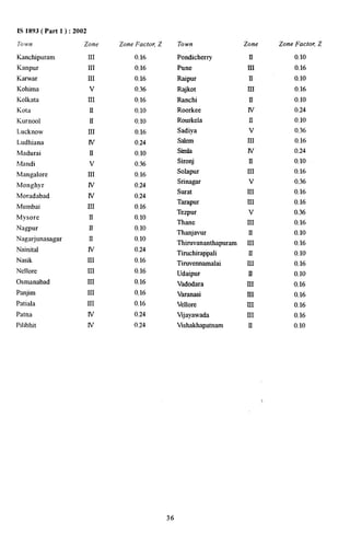
1) The seismic zone map was revised to have 4 zones instead of 5, merging Zone I into Zone II. Zone factors were also changed to reflect realistic peak ground accelerations.
2) Response spectra are now specified for 3 foundation types: rock, medium soil, and soft soil.
3) Empirical expressions for estimating building period were revised.
4) The concept of a response reduction factor was introduced to account for energy dissipation in ductile structures.
![इंटरनेट मानक
Disclosure to Promote the Right To Information
Whereas the Parliament of India has set out to provide a practical regime of right to
information for citizens to secure access to information under the control of public authorities,
in order to promote transparency and accountability in the working of every public authority,
and whereas the attached publication of the Bureau of Indian Standards is of particular interest
to the public, particularly disadvantaged communities and those engaged in the pursuit of
education and knowledge, the attached public safety standard is made available to promote the
timely dissemination of this information in an accurate manner to the public.
“प0रा1 को छोड न' 5 तरफ”
IS 1893-1 (2002): Criteria for Earthquake Resistant Design
of Structures, Part 1: General Provisions and Buildings
[CED 39: Earthquake Engineering]
“!ान $ एक न' भारत का +नम-ण”
Satyanarayan Gangaram Pitroda
“Invent a New India Using Knowledge”
Jawaharlal Nehru
“Step Out From the Old to the New”
“जान1 का अ+धकार, जी1 का अ+धकार”
Mazdoor Kisan Shakti Sangathan
“The Right to Information, The Right to Live”
“!ान एक ऐसा खजाना > जो कभी च0राया नहB जा सकता है”
Bhartṛhari—Nītiśatakam
“Knowledge is such a treasure which cannot be stolen”
हहहै””](https://image.slidesharecdn.com/apsis-1893-140911005918-phpapp02/85/Ap-s-IS-1893-1-2002-1-320.jpg)


![6.4.6 In case design spectrum is specifically prepared
for a structure at a particular project site, the same
may be used for design at the discretion of the project
authorities
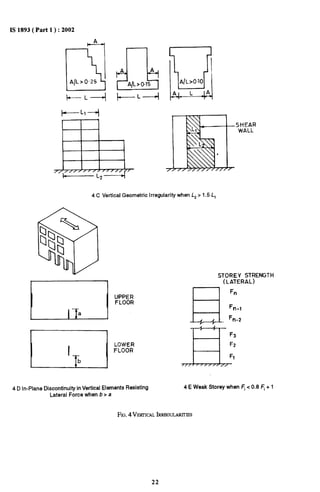
7 BUILDINGS
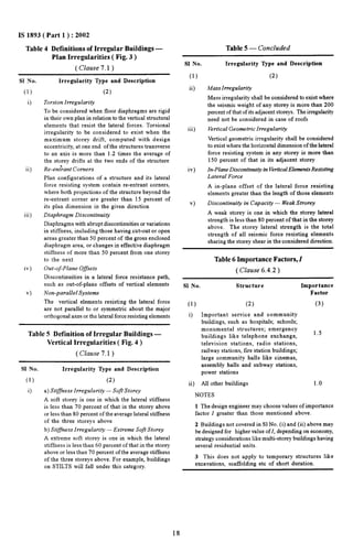
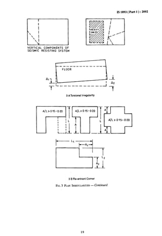
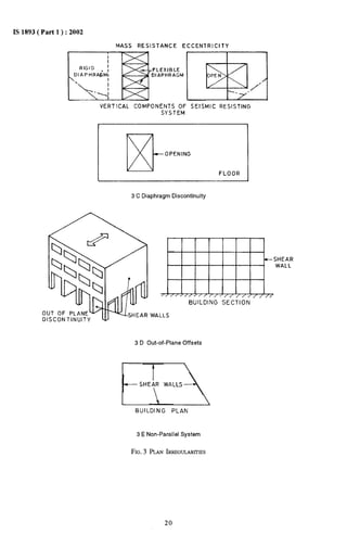
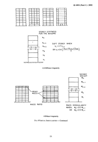
7.1 Regular and Irregular Configuration
To perform well in an earthquake, a building should
possess four main attributes, namely simple and regular
cotilguration, and adequate lateral strength, stiffness
and ductility. Buildings having simple regolar geomet~
and uniformly distributed mass and stiffness in plan
as well as in elevation, suffer much less damage than
buildings with irregular configurations. A building
shall be considered as irregular for the purposes of
this standard, if at least one of the conditions given
in Tables 4 and 5 is applicable,
7.2 Importance Factor Zand Response Reduction
FactorR
The minimum value of importanm factor,1, for ditlerent
building systems shall be as given in Table 6. The
response reduction factor, R, for different building
systems shall be as given in Table 7.
7.3 Design Imposed Loads for Earthquakes Force
Calculation
7.3.1 For various loading classes as specified in
IS 875( Part 2 ), the earthquake force shall be calculatcxl
for the full dead load plus the percentage of imposed
load as given in Table 8.
7.3.2 For calculating the design seismic forces of the
structure, the imposed load on roof need not be
considered.
7.3.3 The percentage of imposed loads given in 7.3.1
and 7.3.2 shall also be used for ‘Whole frame loaded’
condition in the load combinations specified in 6.3.L 1
IS 1893( Part 1 ): 2002
and 6.3.1.2 where the gravity loads are combined with
the earthquake loads [ that is, in load combinations
(3) in 6.3.1.1, and (2) in 6.3.1.2 ]. No further reduction
in the imposed load will be used as envisaged in
IS 875( Part 2 ) for number of storeys above the one
under consideration or for large spans of beams or
floors.
7.3.4 The proportions of imposed load indicated above
for calculating the lateral design forces for earthquakes
are applicable to average conditions. Where the
probable loads at the time of earthquake are more
accurately assessed, the designer may alter the
proportions indicated or even replace the entire
imposed load proportions by the actual assessed load.
In such cases, where the imposed load is not assessed
as per 7.3.1 and 7.3.2 only that part of imposed load,
which possesses mass, shall be considered. Lateral
design force for earthquakes shall not be calculated
on contribution of impact effects from imposed loads.
7.3.5 Other loads apart from those given above ( for
example snow and permanent equipment ) shall be
considered as appropriate.
7.4 Seismic Weight
7.4.1 Seismic Weight of Floors
The seismic weight of each floor is its full dead load
plus appropriate amount of imposed load, as specified
in 7.3.1 and 7.3.2. While computing the seismic weight
of each floor, the weight of columns and walls in any
storey shall be equally distributed to the floors above
and below the storey.
7.4.2 Seismic Weight of Building
The seismic weight of the whole building is the sum
of the seismic weights of all the floors.
7.4.3 Any weight supported in between storeys shall
be distributed to the floors above and below in inverse
proportion to its distance from the floors.
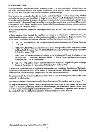
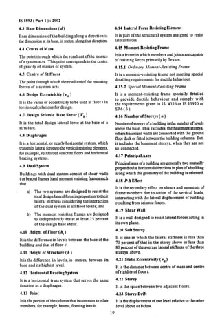
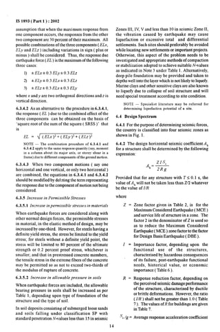
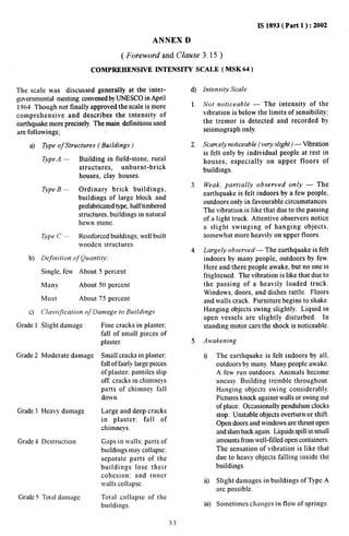
Table 3 Multiplying Factors for Obtaining Values for Other Damping
( Clause 6.4.2)
Damping, o 2 5 7 10 15 20 25 30
percent
Factors 3.20 1,40 1.00 0.90 0.80 0.70 0,60 0.55 0.50
17](https://image.slidesharecdn.com/apsis-1893-140911005918-phpapp02/85/Ap-s-IS-1893-1-2002-21-320.jpg)
![IS 1893( Part 1 ): 2002
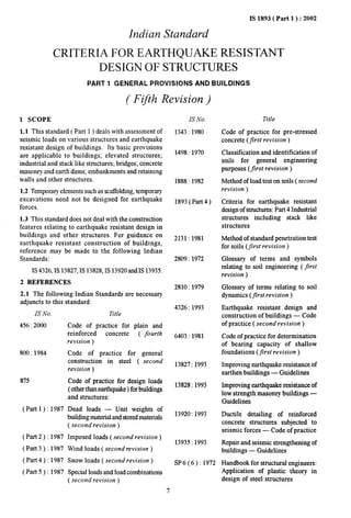
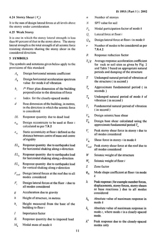
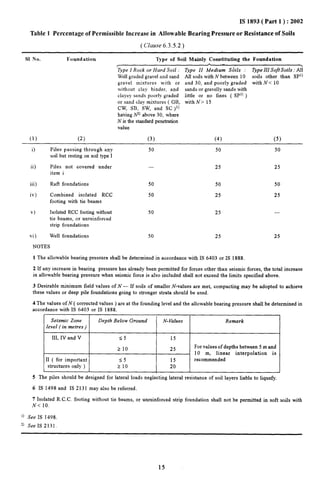
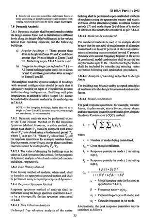
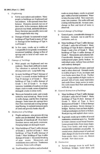
Table 7 Response Reduction Factor l), R, for Building Systems .
( Clause 6.4.2)
S1 No. Lateral Load Resisting System R
(1)
i)
ii)
iii)
iv)
v)
vi)
vii)
viii)
ix)
x)
xi)
(2)
Building Frame Systems
Ordinary RC moment-resisting frame ( OMRF )2)
Special RC moment-resisting frame ( SMRF )3)
Steel frame with
.
a) Concentric braces
b) Eccentric braces
Steel moment resisting frame designed as per SP 6 ( 6 )
Building with Shear Walls4~
Load bearing masonry wall buildings)
a) Unreinforced
b) Reinforced with horizontal RC bands
c) Reinforced with horizontal RC bands and vertical bars at corners of rooms and
jambs of openings
Ordinary reinforced concrete shear walls@
Ductile shear walls7)
Buildings with Dual Systemss)
Ordinary shear wall with OMRF
Ordinary shear wall with SMRF
Ductile shear wall with OMRF
Ductile shear wall with SMRF
(3)
3.0
5.0
4.0
5.0
5.0
1.5
2.5
3.0
3.0
4.0”
3.0
4,0
4.5
5.0
0 The va]ues of response riduction fact&s are to be used for buildings with lateral load resisting elements, and not Just
for the lateral load resisting elements built in isolation.
2) OMRF are those designed and detailedas per IS 456 or Is 800” but not meeting ductile detailing reqllirertleMllt
per IS 13920 or SP 6 (6) respectively.
3)
4)
5)
6)
n
s)
SMRF defined in 4.15.2.
Buildings with shear walls also include buildings having shear walls and frames, but where:
a) frames are not designed to carry lateral loads, or
b) frames are designed to carry lateral loads but do not fulfil the requirements of ‘dual systems’.
Reinforcement should be as per IS 4326.
Prohibited in zones IV and V.
Ductile shear walls are those designed and detailed as per IS 13920.
Buildings with dual systems consist of shear walls ( or braced frames ) and moment resisting frames such that:
a) the two systems are designed to resist the total design force in proportion to their lateral stiffness considering
the interaction of the dual system at all floor levels,; and
b) the moment resisting frames are designed to independently resist at least 25 percent of the design seismic base
shear,
.23](https://image.slidesharecdn.com/apsis-1893-140911005918-phpapp02/85/Ap-s-IS-1893-1-2002-27-320.jpg)


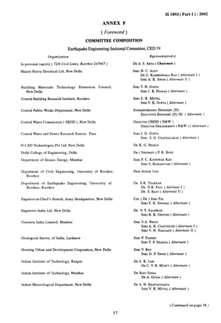
![IS 1893( Part 1 ): 2002
( Continued from page 37)
Organization
Indian Society of Earthquake Technology, Roorkee
Larsen and Toubro, Chennai
Maharashtra Engineering Research Centre ( MERI ), Nasik
Ministry of Surface Transport, New Delhi
National Geophysical Research Institute ( CSIR ), Hyderabad
NationaJ Highway Authority of India, New Delhi
National Hydro-Electric Power Corporation Ltd, New Delhi
National Thermal Power Corporation Ltd, New Delhi
North Eastern Council, Shillong
Nuclear Power Corporation, Mumbai
Railway Board, Ministry of Railways, Lucknow
School of Planning and Architecture, New Delhi
Structural Engineering Research Centre ( CSIR ), Chennai
Tandon Consultants Ltd, New Delhi
Tata Consulting Engineers, Mumbai
Wadia Institute of Himalayan Geology, Debra Dun
In personal capacity ( E-53, Kapil Whan Faridabad )
BIS Directorate GeneraJ
Representative(s)
SHRIM. K. GUPTA
DR D. K. PAUL( Alrernate )
SHRIK. JAYARAMAN
SHRIS. KANAPPAN( Alternate )
SHRIR. L. DAMANI
SHRIS. V. KUMARASWAMY( Alternate )
SHRIN. K. SINHA
SHRIR. S. NINAN( Alternate )
SHRIS. C. BHATIA
SHRIM. RAVIKUMAR( Alternate )
SHRIN. K. SINHA
SHRIG. SHARAN( Alternate )
CHIEPENGINEER,CD-HI
SHRIR. S. BAJAI
SHRIH. K. RAMKUMAR( Alternate )
SHRIL. K. GANJU
SHRIA. D. KHARSHING( Alternate )
SHRtU. S. P. VERMA
EXECUTIVEDIRECTOR( B&S )
JOINTDIRECTOR( B&S ) CB-1 ( Alternate )
SHRIV. THIRUVENDGADAM
SHRIC. V. VAIDYANATErAN
DR B. SWARAMSARMA( Alternate )
DR MAHESHTANDON
SHRIVINAYGUPTA( Alternate )
SHRIK. V. SUBRA~ANIAN
SHRIM. K. S. YOGI( Alternate )
SHRISURINDERKUMAR
SHRIP. L. NARULA
SHRtS.K. JAIN, Director & Head ( Civ Engg )
[ Representing Director General ( Ex-officio ) ]
Member-Secretary
SHRIS. CHATURVEDI
Joint Director ( Civ Engg ), BIS
Earthquake Resistant Construction Subcommittee, CED 39:1
In personal capacity ( 72/6 Civil Lines, Roorkee 247667) DR A. S. ARYA( Convener)
Building Material Technology Promotion Council, New Delhi SHRIT. N. GUPTA
SHRIJ. K. PRASAD( Alternate )
Central Building Research Institute, Roorkee SHRIM. P. JAISINGH
SHRIV. K. GUPTA( Alternate )
( Continued on page 39)
38](https://image.slidesharecdn.com/apsis-1893-140911005918-phpapp02/85/Ap-s-IS-1893-1-2002-42-320.jpg)

Survey of India, Debra Dun SHRIG. M. LAL
39](https://image.slidesharecdn.com/apsis-1893-140911005918-phpapp02/85/Ap-s-IS-1893-1-2002-43-320.jpg)