This document provides an overview and introduction to the book "A Practical Guide to AutoCAD Civil 3D 2017". It includes information about the author, technical editor, and exercise data used in the book. The introduction describes the course objectives and prerequisites. It also explains conventions used like icons to indicate guidance and insights. Finally, it provides instructions for downloading and installing the dataset files needed to complete the exercises in the book.


![Chapter: Building a Survey Quality Surface
Lesson: Building Surfaces from Survey Data 167
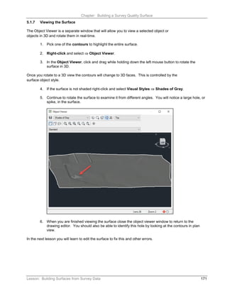
The surface is built with the point group data and displays 5 foot contours colored brown and
green with a yellow border. This display is controlled by the surface style you selected when
you created the surface. If the surface is not visible turn on and thaw the layer C-TOPO-
Survey.
5.1.4 Creating Breaklines by Point Number
Civil 3D does not use special commands for drawing and defining breaklines the way that
Land Desktop and many other programs do. Instead, you draw the breaklines with standard
AutoCAD commands, like the 3D Polyline command, and then define these objects as
breaklines after they have been drawn.
1. Create a new Layer named Breaklines-Survey and set it Current.
2. Thaw the layers PNTS-AEC, PNTS-BREAK, and
PNTS-DRIVEWAY.
3. Freeze the layers C-ANNO, C-PROP, C-PROP-LINE,
C-PROP-TABL, EX-WETLAND-LINE, and PNTS-WTLND.
The drawing will now display the surface as contours and points that you will use for
breaklines. You may need to Regen to clean up the display.
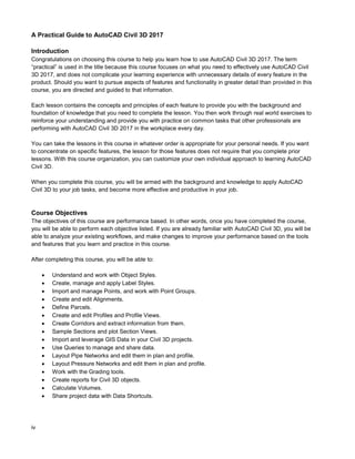
4. Enter 3P at the command line to start the 3D Polyline command.
5. Enter 'PN to change the prompt to Point Number.
Alternatively, you can also select the Point Number button from the Transparent
Commands toolbar.
6. At the command line enter: 1408-1447 and [Enter] to draw the line.
7. [Esc] to end the Point Number prompt.
8. [Enter] to end the line.
9. Enter 3P at the command line to start the 3D Polyline command.](https://image.slidesharecdn.com/apgcivil3d2017tocsample-240225145518-2c4c663e/85/APG_Civil_3D_2017_TOC_Sample-papers-pdf-21-320.jpg)
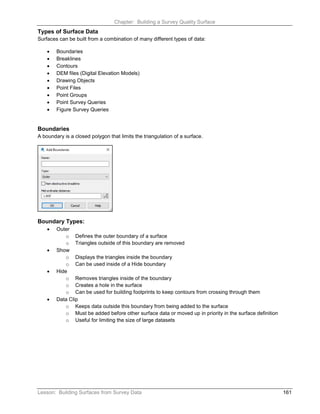
![Chapter: Building a Survey Quality Surface
168 Lesson: Building Surfaces from Survey Data
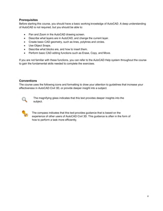
10. Use the points in the following list of points to draw the breaklines the same way that you drew
the previous line. Be sure to use the Point Number transparent command to change the prompt
to Point Number and to end the command completely after drawing each line. Also be sure to
[Enter] after each non-sequential point number as shown below in the list.
Point Numbers
1448-1486
1008-1021
1191-1209
1226-1257
1258-1278
1281-1324
1295 [Enter] 1661-1710
1622-1660 [Enter] 1294
1286 [Enter] 1348-1398 [Enter] 1287
1022-1074
1075-1105
1155-1158
1159-1160
1153-1154
1143-1151
1130-1142
1121-1129
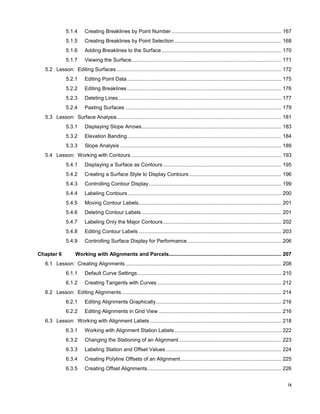
The new 3D Polylines will look like the graphic below. However, they have not yet been
added to the surface as breaklines.
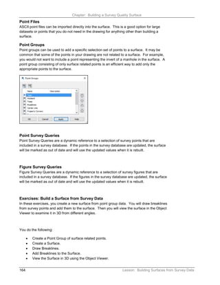
5.1.5 Creating Breaklines by Point Selection
1. On the Prospector tab of the Toolspace, select the Point Group Breaklines.
This will display a list of all the points used in the surface in the preview window at the bottom
of the Prospector, if the Prospector is docked. If the Prospector is not docked it will display
on the side.
2. Find point number 1110 in the preview window.](https://image.slidesharecdn.com/apgcivil3d2017tocsample-240225145518-2c4c663e/85/APG_Civil_3D_2017_TOC_Sample-papers-pdf-22-320.jpg)
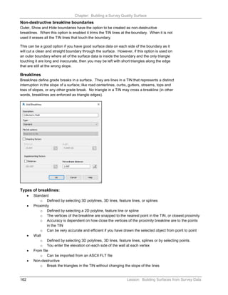
![Chapter: Building a Survey Quality Surface
Lesson: Building Surfaces from Survey Data 169
3. Right-click on point 1110 and select Zoom to. You may want to zoom out some to see the
surrounding points.
4. Enter 3P at the command line to start the 3D Polyline command.
5. Enter 'PO to change the prompt to Point Object.
Alternatively, you can also select the Point Object button from the Transparent
Commands toolbar.
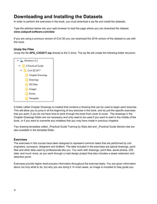
6. Pick point 1110 from the screen.
7. Then pick points 1109, 1108, 1107, and 1106 to draw a breakline between the TOP points toward
the northeast corner of the site.
When using the Point Object transparent command to draw lines between point objects you
will not see the rubber band line that you normally see with the line command.
8. [Enter] to end the Point Object prompt.
9. [Enter] again to end the line.
10. Starting at point 1116, define a second breakline along the bottom of the ditch using the 3D
Polyline command with the 'PO transparent command and points 1116, 1117, 1118, 1119, and
1120.
11. [Enter] to end the Point Object prompt.
12. [Enter] again to end the line.
13. Starting at point 1111, define a third breakline along the bank of the ditch using the 3D Polyline
command with the 'PO transparent command and points 1111, 1112, 1113, 1114, and 1115.
14. [Enter] to end the Point Object prompt.
15. [Enter] again to end the line.
16. Save the drawing.
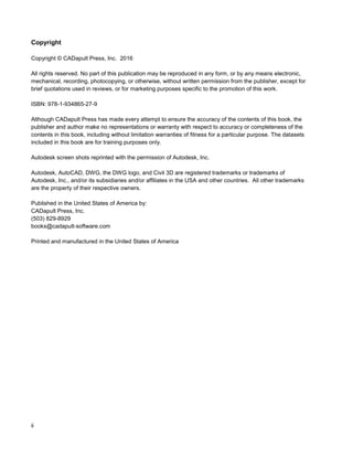
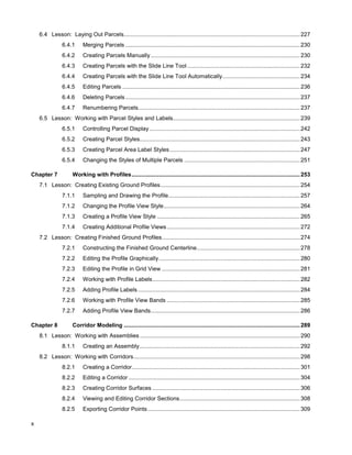
The three new 3D Polylines will look like the graphic below. However, they have not yet been
added to the surface as breaklines.](https://image.slidesharecdn.com/apgcivil3d2017tocsample-240225145518-2c4c663e/85/APG_Civil_3D_2017_TOC_Sample-papers-pdf-23-320.jpg)
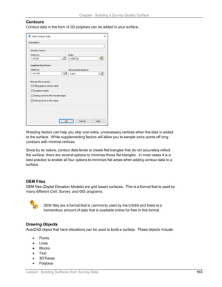
![Chapter: Building a Survey Quality Surface
170 Lesson: Building Surfaces from Survey Data
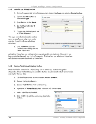
5.1.6 Adding Breaklines to the Surface
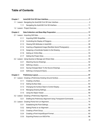
1. Select Ribbon: Home ⇒ Layers ⇒ Isolate.
2. Pick one of the breaklines and one of the contours from the surface to isolate the Breaklines-
Survey and C-TOPO-Survey layers.
3. Confirm that the Definition under the Surface Survey is expanded on the Prospector tab of the
Toolspace.
4. Right-click on Breaklines under the Definition and select ⇒ Add.
5. Enter a Description for the breakline set
of Collected in Field.
6. Confirm that the Type is set to Standard.
You will not use any Weeding or Supplementing
factors in this exercise. These options allow you to
remove or add vertices to breaklines respectively.
These are useful options if you have breaklines that
have been over digitized and may have thousands of
extra vertices very close together or if you need to add
vertices to a breakline that has long distances between
vertices.
7. Click <<OK>>.
8. Select the Breaklines with a crossing window.
9. [Enter] to add the breaklines to the surface.
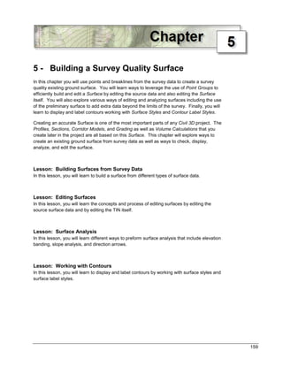
The surface is now updated to include the new breakline data.
10. Select Ribbon: Home ⇒ Layers ⇒ Unisolate to restore the
previous layer state.
11. Save the drawing.](https://image.slidesharecdn.com/apgcivil3d2017tocsample-240225145518-2c4c663e/85/APG_Civil_3D_2017_TOC_Sample-papers-pdf-24-320.jpg)