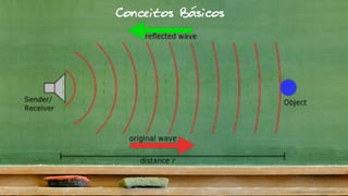
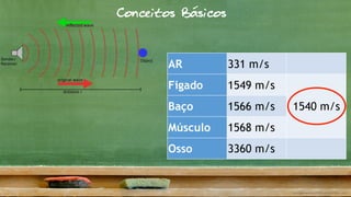
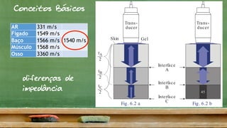
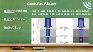
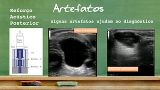
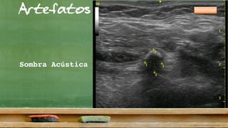
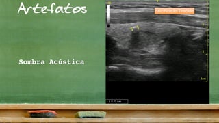
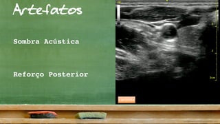
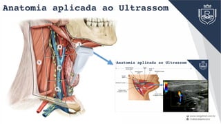
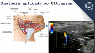
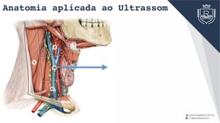
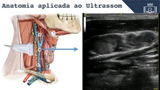
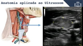
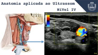
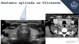
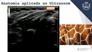
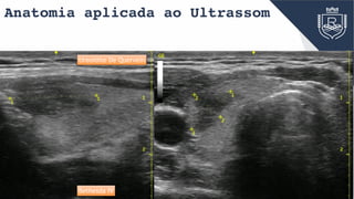
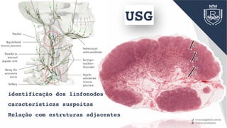
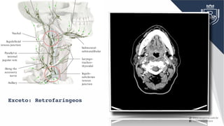
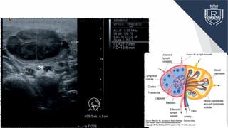
Ultrassonografia
princípios e
anatomia
Dr. Leonardo Guimarães Rangel
Cirurgião de Cabeça e Pescoço
Staff do HUPE-UERJ
antes do curso ……
• Porque um cirurgião faria USG ?
• Eu tenho um radiologista que confio !
• Os radiologistas vão ficar furiosos ?
• Você não manda seus exames para a radiologia ?
• Não tenho tempo de fazer exames e consultas !
Conceitos Básicos
AR 331 m/s
Figado 1549 m/s
1540 m/sBaço 1566 m/s
Músculo 1568 m/s
Osso 3360 m/s
Conceitos Básicos
Conceitos Básicos
AR 331 m/s
Figado 1549 m/s
1540 m/sBaço 1566 m/s
Músculo 1568 m/s
Osso 3360 m/s
Trans-
ducer
Skin Gel
Trans-
ducer
Interface
A
Interface
B
Interface
C
45
t
2
A
t
2
B
t
2
C
face between two tissue layers with differ-
ission properties (interfaces in Fig. 6.2). It is
e that different soft tissues show only minor
transmission of sound (Table 6.1). Only air
ked by massively different sound transmis-
n with other human tissue.
rasound units can be operated at a prese-
equency of approximately 1540 m/s with-
y major inaccuracies in the calculated origin
cho. The processor computes the depth of
from the time difference detected between
und impulse and return of the echo. Echoes
o the transducer (A) arrive earlier (tA) than
per tissues (tB, tC in Fig. 6.2a). The mean
tly theoretical since the processor cannot
of tissue was traversed.
nt of the Sound Wave is Reflected?
ree tissue blocks traversed by sound waves
inimally in their transmission velocity (in-
Table 6.1
Fig. 6.2 a Fig. 6.2 b
sound waves deep to this structure from which it can gener-
ate an image. Instead, the total reflection creates an acoustic
diferenças de
impedância
Trans-
ducer
Skin Gel
Trans-
ducer
Interface
A
Interface
B
Interface
C
45
t
2
A
t
2
B
t
2
C
Muscle 1568 m/s
Bone 3360 m/s
Table 6.1
Fig. 6.2 a Fig. 6.2 b
sound waves deep to this structure from which it can gener-
ate an image. Instead, the total reflection creates an acoustic
shadow (45).
Conceitos Básicos
Conceitos Básicos
Trans-
ducer
Skin Gel
Trans-
ducer
Interface
A
Interface
B
Interface
C
45
t
2
A
t
2
B
t
2
C
waves that are sent by a transducer into the human body and
reflected there. In abdominal ultrasound, the frequencies
used generally are between 2.5 and 5.0 megahertz (MHz; see
p. 9).
The primary condition required for sound wave reflections is
the presence of so-called “impedance mismatches.” These
occur at the interface between two tissue layers with differ-
ent sound transmission properties (interfaces in Fig. 6.2). It is
interesting to note that different soft tissues show only minor
differences in the transmission of sound (Table 6.1). Only air
and bone are marked by massively different sound transmis-
sion in comparison with other human tissue.
For this reason ultrasound units can be operated at a prese-
lected medium frequency of approximately 1540 m/s with-
out producing any major inaccuracies in the calculated origin
(“depth”) of the echo. The processor computes the depth of
origin of the echo from the time difference detected between
emission of the sound impulse and return of the echo. Echoes
from tissue close to the transducer (A) arrive earlier (tA) than
echoes from deeper tissues (tB, tC in Fig. 6.2a). The mean
frequency is strictly theoretical since the processor cannot
know which type of tissue was traversed.
Which Component of the Sound Wave is Reflected?
Fig. 6.2a shows three tissue blocks traversed by sound waves
that differ only minimally in their transmission velocity (in-
dicated by similar gray values). Each interface only reflects a
small portion of the original sound waves (m ) as echo (i ).
Air 331 m/s
Liver 1549 m/s
Spleen 1566 m/s
Muscle 1568 m/s
Bone 3360 m/s
Sound Transmission in Human Tissue
Table 6.1
Fig. 6.2 a Fig. 6.2 b
sound waves deep to this structure from which it can gener-
ate an image. Instead, the total reflection creates an acoustic
shadow (45).
mean =1540 m/s
HiperEcóico - mais claro
HipoEcoico - mais escuro
AnEcóico - preto
Conceitos Básicos
HiperEcóico
HipoEcoico
AnEcóico
Trans-
ducer
Skin Gel
Trans-
ducer
Interface
A
Interface
B
Interface
C
45
t
2
A
t
2
B
t
2
C
ies (interfaces in Fig. 6.2). It is
t soft tissues show only minor
of sound (Table 6.1). Only air
vely different sound transmis-
uman tissue.
s can be operated at a prese-
pproximately 1540 m/s with-
uracies in the calculated origin
cessor computes the depth of
e difference detected between
and return of the echo. Echoes
ucer (A) arrive earlier (tA) than
B, tC in Fig. 6.2a). The mean
l since the processor cannot
raversed.
nd Wave is Reflected?
cks traversed by sound waves
Fig. 6.2 a Fig. 6.2 b
sound waves deep to this structure from which it can gener-
não é uma função da massa ou densidade
tem relação com diferença de impedância
Conceitos Básicos
6-2 MHz 10-5 MHz
maior penetração
pior definição
menor penetração
melhor definição
Conceitos Básicos
can greatly degrade image quality. Conse-
Linear
4545
7.5 MHz
Convex (curved array)
45 45
3.75 MHz
Sector
Ribs
60°
90°
2.5
MHz
Fig. 9.2 a Fig. 9.2 b Fig. 9.2 c
Artefatos
O monitor nem sempre
reflete a verdadeira
ecogenecidade dos
tecidos e não
representa a
verdadeira anatomia.
Interação do som com os tecidos
1. Resolução axial e lateral
2. Interferência
3. Espessura do feixe
4. Reflexão
Reverberação
Trajetória múltipla
Imagem em espelho
5. Refração
6. Lobos laterais
7. Atenuação
Sombra
Reforço
ArtefatosReforço
Acústico
Posterior
3
2
46
4538
70
45
51a
46
70
70
77
77
51b
ways return directly from the point of reflection to the trans-
ucer. The processor makes the same assumption when com-
uting the depth of the site of reflection. In reality, this is not
ways the case:
n their wayback to the transducer, the reflected sound waves
n encounter an impedance mismatch that reflects some of
em back into deeper tissue. There they are again reflected
Usually this phenomenon is lost in the background noise of
the image. However, against an anechoic background such
as the lumen of the urinary bladder (38) or gallbladder, these
reverberations appear as lines parallel to the anterior abdomi-
nal wall (51a in Fig. 16.2). These sound waves can “bounce
back and forth” repeatedly, producing a series of parallel lines
(51a).
Trans-
ducer
Skin Gel
Interface A
Interface B
51a
ction Thickness Artifacts
he far wall of the bladder can appear similarly indistinct. If
e bladder wall (77), cyst, or gallbladder is not perpendicular
g. 16.1 Fig. 16.2 a Fig. 16.2 b
Fig. 16.3). However, these are usually more sharply demar-
cated from the remaining lumen and can be disturbed with
cisto tireoidiano
adenoma pleomórfico
alguns artefatos ajudam no diagnóstico
Artefatos
Sombra Acústica
Sialolitíase
Artefatos
Sombra Acústica
calcificação Tireóide
Artefatos
Sombra Acústica
carótida
Reforço Posterior
Artefatos
Sombra Acústica
carótida
Reforço Posterior
Artefatos
Cristais de Colóide
alguns artefatos ajudam
MUITO no diagnóstico
pontos hiperecóicos
com cauda de cometa
Reverberação
Artefatos
Cristais de Colóide
alguns artefatos ajudam
MUITO no diagnóstico
pontos hiperecóicos
com cauda de cometa
Reverberação
Anatomia aplicada ao Ultrassom
Pescoço
Anatomia aplicada ao Ultrassom
IV
V
III VI
I
II
Anatomia aplicada ao Ultrassom
Facial
vein
Submandibular
gland
Parotid
gland
Facial
artery
Posterior belly
of digastric muscle
Anterior belly
of digastric muscle
Mylohyoid muscle
Stylohyoid muscle
Submandibular
lymph nodes
CHAPTER 9 Salivary Glands 147
Anatomia aplicada ao Ultrassom
Facial
vein
Submandibular
gland
Parotid
gland
Facial
artery
Posterior belly
of digastric muscle
Anterior belly
of digastric muscle
Mylohyoid muscle
Stylohyoid muscle
Submandibular
lymph nodes
CHAPTER 9 Salivary Glands 147
Anatomia aplicada ao Ultrassom
IV
V
III VI
I
II
Anatomia aplicada ao Ultrassom
IV
V
III VI
I
II
Anatomia aplicada ao Ultrassom
IV
V
III VI
I
II
Anatomia aplicada ao Ultrassom
IV
V
III VI
I
II
the head region drain into lymph nodes in the
neck located close to the head.
NíVel IV
Anatomia aplicada ao Ultrassom
IV
V
III VI
I
II
the head region drain into lymph nodes in the
neck located close to the head.
NíVel IV
Anatomia aplicada ao Ultrassom
Tireóide
Anatomia aplicada ao Ultrassom
Head & Neck Anatomy
Anatomia aplicada ao Ultrassom
tireoidite
Anatomia aplicada ao Ultrassom
tireoidite
Anatomia aplicada ao Ultrassom
tireoidite De Quervein
Bethesda IV
Anatomia aplicada ao Ultrassom
Linfonodos
ThoracicRight
Jugulo-
subclavian
venous
junction
Laryngo-
tracheo-
thyroidal
Submental-
submandibular
Nuchal
Jugulofacial
venous junction
Parallel to
internal
jugular vein
Along the
accessory
nerve
Axillary
C Directions of lymphatic drainage in the neck
Right lateral view. The principal pattern of lymphatic ow in the neck
is depicted. Understanding this pattern is critical to identifying the lo-
cation of a potential cause of enlarged cervical lymph nodes. There are
two main sites in the neck where the lymphatic pathways intersect:
• The jugulofacial venous junction: Lymphatics from the head pass
obliquely downward to this site, where the lymph is redirected verti-
cally downward in the neck.
• The jugulosubclavian venous junction: The main lymphatic trunk, the
thoracic duct, terminates at this central location, where lymph col-
lected from the left side of the head and neck region is combined
with lymph draining from the rest of the body.
If only peripheral nodal groups are a ected, this suggests a localized
disease process. If the central groups (e.g., those at the venous junc-
tions) are a ected, this usually signi es an extensive disease process.
Central lymph nodes can be obtained for diagnostic evaluation by pres-
calene biopsy.
USG
identificação dos linfonodos
características suspeitas
Relação com estruturas adjacentes
ThoracicRight
Jugulo-
subclavian
venous
junction
Laryngo-
tracheo-
thyroidal
Submental-
submandibular
Nuchal
Jugulofacial
venous junction
Parallel to
internal
jugular vein
Along the
accessory
nerve
Axillary
C Directions of lymphatic drainage in the neck
Right lateral view. The principal pattern of lymphatic ow in the neck
is depicted. Understanding this pattern is critical to identifying the lo-
cation of a potential cause of enlarged cervical lymph nodes. There are
two main sites in the neck where the lymphatic pathways intersect:
• The jugulofacial venous junction: Lymphatics from the head pass
obliquely downward to this site, where the lymph is redirected verti-
cally downward in the neck.
• The jugulosubclavian venous junction: The main lymphatic trunk, the
thoracic duct, terminates at this central location, where lymph col-
lected from the left side of the head and neck region is combined
with lymph draining from the rest of the body.
If only peripheral nodal groups are a ected, this suggests a localized
disease process. If the central groups (e.g., those at the venous junc-
tions) are a ected, this usually signi es an extensive disease process.
Central lymph nodes can be obtained for diagnostic evaluation by pres-
calene biopsy.
Exceto: Retrofaríngeos
Fig. 6.2a Right side of the neck, transvers
II. An oval lymph node in acute lympha
colli (RF); the node has a delicate intern
pattern with well-defined margins and m
30mm × 15mm in both short-axis dia
A clearly visible incidental finding is the
bundle of the vagus nerve seen in cross-
between the internal (ACI) and externa
carotid arteries (asterisk). GSM, subman
gland.
*
No changes in the size or form
of the lymph node are evident.
Thickness is first affected
(6 mm or greater in thickness).
The capsule also becomes thicker.
Although the entire lymph
node becomes enlarged,
the capsule is retained.
A metastatic focus occupies
almost the entire lymph node.
A border is clearly observed
(10–20 mm in thickness;
can be identified even by CT).
The metastatic focus
extends beyond the capsule
of the lymph node into
surrounding tissues. The border
becomes poorly demarcated.
1 2 3
7 6 5
4
No changes in the size or form
of the lymph node are evident.
T
1 2
7 6
No changes in the size or form
of the lymph node are evident.
Thickness is first affected
(6 mm or greater in thickness).
The capsule also becomes thicker.
1 2 3
7 6 5
4
Fig. 6.23 Left side of the neck, longitudinal,
level III. A round lymph node metastasis with
irregular borders has an anechoic center, which
is indicative of necrosis caused by the metastatic
transformation. VJI, internal jugular vein; MSCM,
sternocleidomastoid muscle.
Fig. 6.24 Left side of the neck, level II. Medial to
the internal and external carotid arteries, the round
metastasis has an anechoic center consistent with
central necrosis; this is considered to be a sign of
malignancy. To the left, medial in the image, is an
ill-defined hypoechoic primary tumor (TU) of the
left side of the oropharynx. The internal jugular
vein (VJI) is compromised and can be seen between
the anterior border of the sternocleidomastoid
muscle (MSCM) and the internal carotid artery
(ACI). The vein can be demonstrated better with
a Valsalva maneuver. ACE, external carotid artery.
No changes in the size or form
of the lymph node are evident.
Thickness is first affected
(6 mm or greater in thickness).
The capsule also becomes thicker.
Although the entire lymph
node becomes enlarged,
the capsule is retained.
A metastatic focus occupies
almost the entire lymph node.
A border is clearly observed
(10–20 mm in thickness;
can be identified even by CT).
The metastatic focus
extends beyond the capsule
of the lymph node into
surrounding tissues. The border
becomes poorly demarcated.
1 2 3
7 6 5
4
Anatomia aplicada ao Ultrassom
Outras Lesões
lipoma de parótida
diagnóstico
programação
intra-operatório
Cisto Branquial
Cisto Tireoglosso
obrigado
www.slideshare.net/leonardograngel
Anatomia ultrassonográfica

Anatomia ultrassonográfica

  • 1.
    Ultrassonografia princípios e anatomia Dr. LeonardoGuimarães Rangel Cirurgião de Cabeça e Pescoço Staff do HUPE-UERJ
  • 2.
    antes do curso…… • Porque um cirurgião faria USG ? • Eu tenho um radiologista que confio ! • Os radiologistas vão ficar furiosos ? • Você não manda seus exames para a radiologia ? • Não tenho tempo de fazer exames e consultas !
  • 3.
  • 4.
    AR 331 m/s Figado1549 m/s 1540 m/sBaço 1566 m/s Músculo 1568 m/s Osso 3360 m/s Conceitos Básicos
  • 5.
    Conceitos Básicos AR 331m/s Figado 1549 m/s 1540 m/sBaço 1566 m/s Músculo 1568 m/s Osso 3360 m/s Trans- ducer Skin Gel Trans- ducer Interface A Interface B Interface C 45 t 2 A t 2 B t 2 C face between two tissue layers with differ- ission properties (interfaces in Fig. 6.2). It is e that different soft tissues show only minor transmission of sound (Table 6.1). Only air ked by massively different sound transmis- n with other human tissue. rasound units can be operated at a prese- equency of approximately 1540 m/s with- y major inaccuracies in the calculated origin cho. The processor computes the depth of from the time difference detected between und impulse and return of the echo. Echoes o the transducer (A) arrive earlier (tA) than per tissues (tB, tC in Fig. 6.2a). The mean tly theoretical since the processor cannot of tissue was traversed. nt of the Sound Wave is Reflected? ree tissue blocks traversed by sound waves inimally in their transmission velocity (in- Table 6.1 Fig. 6.2 a Fig. 6.2 b sound waves deep to this structure from which it can gener- ate an image. Instead, the total reflection creates an acoustic diferenças de impedância
  • 6.
    Trans- ducer Skin Gel Trans- ducer Interface A Interface B Interface C 45 t 2 A t 2 B t 2 C Muscle 1568m/s Bone 3360 m/s Table 6.1 Fig. 6.2 a Fig. 6.2 b sound waves deep to this structure from which it can gener- ate an image. Instead, the total reflection creates an acoustic shadow (45). Conceitos Básicos
  • 7.
    Conceitos Básicos Trans- ducer Skin Gel Trans- ducer Interface A Interface B Interface C 45 t 2 A t 2 B t 2 C wavesthat are sent by a transducer into the human body and reflected there. In abdominal ultrasound, the frequencies used generally are between 2.5 and 5.0 megahertz (MHz; see p. 9). The primary condition required for sound wave reflections is the presence of so-called “impedance mismatches.” These occur at the interface between two tissue layers with differ- ent sound transmission properties (interfaces in Fig. 6.2). It is interesting to note that different soft tissues show only minor differences in the transmission of sound (Table 6.1). Only air and bone are marked by massively different sound transmis- sion in comparison with other human tissue. For this reason ultrasound units can be operated at a prese- lected medium frequency of approximately 1540 m/s with- out producing any major inaccuracies in the calculated origin (“depth”) of the echo. The processor computes the depth of origin of the echo from the time difference detected between emission of the sound impulse and return of the echo. Echoes from tissue close to the transducer (A) arrive earlier (tA) than echoes from deeper tissues (tB, tC in Fig. 6.2a). The mean frequency is strictly theoretical since the processor cannot know which type of tissue was traversed. Which Component of the Sound Wave is Reflected? Fig. 6.2a shows three tissue blocks traversed by sound waves that differ only minimally in their transmission velocity (in- dicated by similar gray values). Each interface only reflects a small portion of the original sound waves (m ) as echo (i ). Air 331 m/s Liver 1549 m/s Spleen 1566 m/s Muscle 1568 m/s Bone 3360 m/s Sound Transmission in Human Tissue Table 6.1 Fig. 6.2 a Fig. 6.2 b sound waves deep to this structure from which it can gener- ate an image. Instead, the total reflection creates an acoustic shadow (45). mean =1540 m/s HiperEcóico - mais claro HipoEcoico - mais escuro AnEcóico - preto
  • 8.
    Conceitos Básicos HiperEcóico HipoEcoico AnEcóico Trans- ducer Skin Gel Trans- ducer Interface A Interface B Interface C 45 t 2 A t 2 B t 2 C ies(interfaces in Fig. 6.2). It is t soft tissues show only minor of sound (Table 6.1). Only air vely different sound transmis- uman tissue. s can be operated at a prese- pproximately 1540 m/s with- uracies in the calculated origin cessor computes the depth of e difference detected between and return of the echo. Echoes ucer (A) arrive earlier (tA) than B, tC in Fig. 6.2a). The mean l since the processor cannot raversed. nd Wave is Reflected? cks traversed by sound waves Fig. 6.2 a Fig. 6.2 b sound waves deep to this structure from which it can gener- não é uma função da massa ou densidade tem relação com diferença de impedância
  • 9.
    Conceitos Básicos 6-2 MHz10-5 MHz maior penetração pior definição menor penetração melhor definição
  • 10.
    Conceitos Básicos can greatlydegrade image quality. Conse- Linear 4545 7.5 MHz Convex (curved array) 45 45 3.75 MHz Sector Ribs 60° 90° 2.5 MHz Fig. 9.2 a Fig. 9.2 b Fig. 9.2 c
  • 11.
    Artefatos O monitor nemsempre reflete a verdadeira ecogenecidade dos tecidos e não representa a verdadeira anatomia. Interação do som com os tecidos 1. Resolução axial e lateral 2. Interferência 3. Espessura do feixe 4. Reflexão Reverberação Trajetória múltipla Imagem em espelho 5. Refração 6. Lobos laterais 7. Atenuação Sombra Reforço
  • 12.
    ArtefatosReforço Acústico Posterior 3 2 46 4538 70 45 51a 46 70 70 77 77 51b ways return directlyfrom the point of reflection to the trans- ucer. The processor makes the same assumption when com- uting the depth of the site of reflection. In reality, this is not ways the case: n their wayback to the transducer, the reflected sound waves n encounter an impedance mismatch that reflects some of em back into deeper tissue. There they are again reflected Usually this phenomenon is lost in the background noise of the image. However, against an anechoic background such as the lumen of the urinary bladder (38) or gallbladder, these reverberations appear as lines parallel to the anterior abdomi- nal wall (51a in Fig. 16.2). These sound waves can “bounce back and forth” repeatedly, producing a series of parallel lines (51a). Trans- ducer Skin Gel Interface A Interface B 51a ction Thickness Artifacts he far wall of the bladder can appear similarly indistinct. If e bladder wall (77), cyst, or gallbladder is not perpendicular g. 16.1 Fig. 16.2 a Fig. 16.2 b Fig. 16.3). However, these are usually more sharply demar- cated from the remaining lumen and can be disturbed with cisto tireoidiano adenoma pleomórfico alguns artefatos ajudam no diagnóstico
  • 13.
  • 14.
  • 15.
  • 16.
  • 17.
    Artefatos Cristais de Colóide algunsartefatos ajudam MUITO no diagnóstico pontos hiperecóicos com cauda de cometa Reverberação
  • 18.
    Artefatos Cristais de Colóide algunsartefatos ajudam MUITO no diagnóstico pontos hiperecóicos com cauda de cometa Reverberação
  • 19.
    Anatomia aplicada aoUltrassom Pescoço
  • 20.
    Anatomia aplicada aoUltrassom IV V III VI I II
  • 21.
    Anatomia aplicada aoUltrassom Facial vein Submandibular gland Parotid gland Facial artery Posterior belly of digastric muscle Anterior belly of digastric muscle Mylohyoid muscle Stylohyoid muscle Submandibular lymph nodes CHAPTER 9 Salivary Glands 147
  • 22.
    Anatomia aplicada aoUltrassom Facial vein Submandibular gland Parotid gland Facial artery Posterior belly of digastric muscle Anterior belly of digastric muscle Mylohyoid muscle Stylohyoid muscle Submandibular lymph nodes CHAPTER 9 Salivary Glands 147
  • 23.
    Anatomia aplicada aoUltrassom IV V III VI I II
  • 24.
    Anatomia aplicada aoUltrassom IV V III VI I II
  • 25.
    Anatomia aplicada aoUltrassom IV V III VI I II
  • 26.
    Anatomia aplicada aoUltrassom IV V III VI I II the head region drain into lymph nodes in the neck located close to the head. NíVel IV
  • 27.
    Anatomia aplicada aoUltrassom IV V III VI I II the head region drain into lymph nodes in the neck located close to the head. NíVel IV
  • 28.
    Anatomia aplicada aoUltrassom Tireóide
  • 29.
    Anatomia aplicada aoUltrassom Head & Neck Anatomy
  • 30.
    Anatomia aplicada aoUltrassom tireoidite
  • 31.
    Anatomia aplicada aoUltrassom tireoidite
  • 32.
    Anatomia aplicada aoUltrassom tireoidite De Quervein Bethesda IV
  • 33.
    Anatomia aplicada aoUltrassom Linfonodos
  • 34.
    ThoracicRight Jugulo- subclavian venous junction Laryngo- tracheo- thyroidal Submental- submandibular Nuchal Jugulofacial venous junction Parallel to internal jugularvein Along the accessory nerve Axillary C Directions of lymphatic drainage in the neck Right lateral view. The principal pattern of lymphatic ow in the neck is depicted. Understanding this pattern is critical to identifying the lo- cation of a potential cause of enlarged cervical lymph nodes. There are two main sites in the neck where the lymphatic pathways intersect: • The jugulofacial venous junction: Lymphatics from the head pass obliquely downward to this site, where the lymph is redirected verti- cally downward in the neck. • The jugulosubclavian venous junction: The main lymphatic trunk, the thoracic duct, terminates at this central location, where lymph col- lected from the left side of the head and neck region is combined with lymph draining from the rest of the body. If only peripheral nodal groups are a ected, this suggests a localized disease process. If the central groups (e.g., those at the venous junc- tions) are a ected, this usually signi es an extensive disease process. Central lymph nodes can be obtained for diagnostic evaluation by pres- calene biopsy. USG identificação dos linfonodos características suspeitas Relação com estruturas adjacentes
  • 35.
    ThoracicRight Jugulo- subclavian venous junction Laryngo- tracheo- thyroidal Submental- submandibular Nuchal Jugulofacial venous junction Parallel to internal jugularvein Along the accessory nerve Axillary C Directions of lymphatic drainage in the neck Right lateral view. The principal pattern of lymphatic ow in the neck is depicted. Understanding this pattern is critical to identifying the lo- cation of a potential cause of enlarged cervical lymph nodes. There are two main sites in the neck where the lymphatic pathways intersect: • The jugulofacial venous junction: Lymphatics from the head pass obliquely downward to this site, where the lymph is redirected verti- cally downward in the neck. • The jugulosubclavian venous junction: The main lymphatic trunk, the thoracic duct, terminates at this central location, where lymph col- lected from the left side of the head and neck region is combined with lymph draining from the rest of the body. If only peripheral nodal groups are a ected, this suggests a localized disease process. If the central groups (e.g., those at the venous junc- tions) are a ected, this usually signi es an extensive disease process. Central lymph nodes can be obtained for diagnostic evaluation by pres- calene biopsy. Exceto: Retrofaríngeos
  • 36.
    Fig. 6.2a Rightside of the neck, transvers II. An oval lymph node in acute lympha colli (RF); the node has a delicate intern pattern with well-defined margins and m 30mm × 15mm in both short-axis dia A clearly visible incidental finding is the bundle of the vagus nerve seen in cross- between the internal (ACI) and externa carotid arteries (asterisk). GSM, subman gland. *
  • 37.
    No changes inthe size or form of the lymph node are evident. Thickness is first affected (6 mm or greater in thickness). The capsule also becomes thicker. Although the entire lymph node becomes enlarged, the capsule is retained. A metastatic focus occupies almost the entire lymph node. A border is clearly observed (10–20 mm in thickness; can be identified even by CT). The metastatic focus extends beyond the capsule of the lymph node into surrounding tissues. The border becomes poorly demarcated. 1 2 3 7 6 5 4
  • 38.
    No changes inthe size or form of the lymph node are evident. T 1 2 7 6
  • 39.
    No changes inthe size or form of the lymph node are evident. Thickness is first affected (6 mm or greater in thickness). The capsule also becomes thicker. 1 2 3 7 6 5 4
  • 40.
    Fig. 6.23 Leftside of the neck, longitudinal, level III. A round lymph node metastasis with irregular borders has an anechoic center, which is indicative of necrosis caused by the metastatic transformation. VJI, internal jugular vein; MSCM, sternocleidomastoid muscle. Fig. 6.24 Left side of the neck, level II. Medial to the internal and external carotid arteries, the round metastasis has an anechoic center consistent with central necrosis; this is considered to be a sign of malignancy. To the left, medial in the image, is an ill-defined hypoechoic primary tumor (TU) of the left side of the oropharynx. The internal jugular vein (VJI) is compromised and can be seen between the anterior border of the sternocleidomastoid muscle (MSCM) and the internal carotid artery (ACI). The vein can be demonstrated better with a Valsalva maneuver. ACE, external carotid artery. No changes in the size or form of the lymph node are evident. Thickness is first affected (6 mm or greater in thickness). The capsule also becomes thicker. Although the entire lymph node becomes enlarged, the capsule is retained. A metastatic focus occupies almost the entire lymph node. A border is clearly observed (10–20 mm in thickness; can be identified even by CT). The metastatic focus extends beyond the capsule of the lymph node into surrounding tissues. The border becomes poorly demarcated. 1 2 3 7 6 5 4
  • 41.
    Anatomia aplicada aoUltrassom Outras Lesões
  • 42.
  • 43.
  • 44.
  • 45.