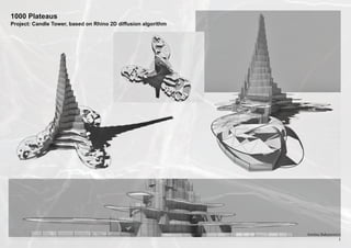
2. 1000 Plateaus
Project: Candle Tower, based on Rhino 2D diffusion algorithm
The main goals of the project:
1. Explore the possibilities of the 2D diffusion algorithm and apply one to a 3D model
2. Find suitable pattern for the canopies of the tower and code it.
3. Make sure that the resulting model has a very strong architectural appeal.
The outcome of the project:
1. The initial goals of the project are met
2. The final model looks like a complete a piece of architecture, however it has few resolvable
functional and structural issues.
3. The code can be applied to any footprint of the future tower. The tower and all its elements
can be build according to the geometry of the chosen Ground Floor curve
4. The amount of the models is infinite as the code has vast variety of model-controlling variables, like the floor height, number of floors, rotation angle of each floor, number of canopy
panels and net strings, size of the canopy panels, number of window panes per floor, etc.
5. The code can be extended by adding functions controlling the transparency of the canopy
panels, their concentration or their size according to various sun conditions. Supporting elements for the canopies can be added as well.
Fig. 1
Fig. 2
Fig. 3
Fig. 4
Inspiration:
Inspiration for the the canopy design came from the cracking, net-like patterns of the river ice,
elephant skin, section throught the marble slab, dried out paints and gels, ceramic cracks,
parched earth, etc. :
Construction of the tower
curves:
- The initial curve representing the
Ground Floor footprint. (Figs. 1,2,3)
- The points of the curve are interpolated and create the outline curve of
the 1st Floor. Then it is rotated by a
user chosen angle around the axis of
the future tower. (Fig. 4)
- All the floor curves (Fig. 5)
Fig. 5
Amiina Bakunowicz
2
3. 1000 Plateaus
Project: Candle Tower, based on Rhino 2D diffusion algorithm
Fig. 11
Construction of the glazing and balustrades:
-The initial curve representing the Ground Floor footprint is divided by a user chosen
number(Fig. 6).
-New polyline is created based on the division points of the curve and the original
curve is deleted (Fig. 7).
-New polyline is the final shape of the slab. Balustrade posts are built from the each
point. Planar surface is added in between of all posts representing the balustrade glazing. The same process is repeated for each floor (Fig. 8)
-As soon as the slab and the balustrade ofthe next floor up are constructed the glazing frames are created for the floor below (Figs. 9 &10))
Fig. 6
Fig. 9
-The final model (Fig.11)
Fig. 7
Fig. 9
Fig. 10
Fig. 8
Amiina Bakunowicz
3
4. 1000 Plateaus
Construction of the canopies:
Project: Candle Tower, based on Rhino 2D diffusion algorithm
-The original construction curve of each floor is copied in Z
direction and the offset outwards to create the overhang for the
future canopy (Figs. 12 & 13)
Fig. 12
-The curve is then divided by the same amount as the original
floor curve. User specified amount of pairs of random points create
net of lines(Fig.14)
-All intersection points are then put in a separate list (Fig.15)
-Those points then are projected on a temporarily created surface of the canopy (Fig. 16)
-Also the lines are projected to thesame surface and then given
volume to represent wire strings of the canopy (Fig. 17)
-A random point is picked from the list of intersection points.
Then all the points within user defined range are found.
Fig. 13
Fig. 14
Fig. 15
-Two further points are selected from the new list. A panel
is created by adding a planar surface between three points.
The same process is repeated for the user defined number of
times,generating an organic pattern of the canopy (Fig. 18)
Fig. 16
Fig. 17
Pseudo Code: Creating the Canopies
# Creates points along the canopy curve which will be
# Deletes construction NetLines and surface (Fig. 17)
connected with lines later
# Loop that creates panels by adding a surface be
# Loop that creates lines connecting random points
tween three points within defined distance range from
on the curve and projects the lines on the surface,
each other (F.18)
which will be deleted at the end of the function (14)
# goes through each element of the intersec
# Defines Min and Max of the distancerange between
tion points list and assigns coordinates to
the points
point 1
# Loop with the range of No of panels required:
# checks the distance between point 1 and
# Projects all lines to the construction sur
the rest and finds all the points within the
face CurveSrf (Fig.17)
range Rmin and Rmax. Appends the selected
points to the temp list “pts”
# As lines are projected each of them can be
divided into few. The lines that are outside of
# points two and three are the random points
the floor curve don’t get projected and their
from the list “pts”
value is []. This conditional makes sure that
all projected lines get thickness and added to
a separate layer for ease of future rendering # creates a planar surface between three
points
# Loop with range of No of the net lines:
# finds intersection points of all the lines in
NetLines list and appends the points to a
relevant list. This list will be used later to cre-
ate panels (Fig. 15)
Fig. 18
Amiina Bakunowicz
4