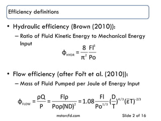
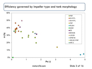
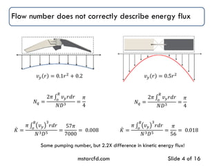
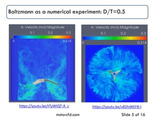
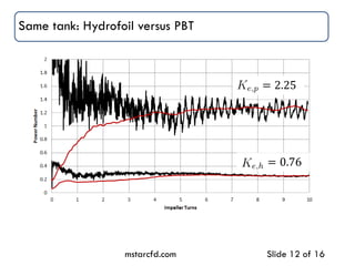
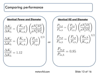
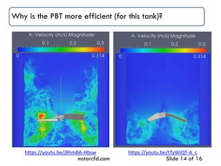
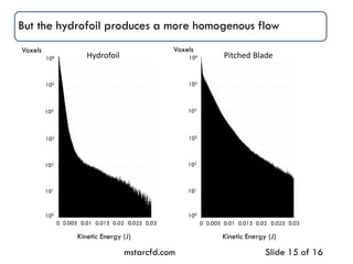
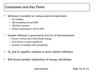
A New Definition of Impeller Efficiency
John A. Thomas, PhD
&
Richard K. Grenville, PhD
AIChE Annual Meeting
Salt Lake City, UT.
12 November 2015
Efficiency definitions
• Hydraulic efficiency (Brown (2010)):
– Ratio of Fluid Kinetic Energy to Mechanical Energy
Input
• Flow efficiency (after Fořt et al. (2010)):
– Mass of Fluid Pumped per Joule of Energy Input
mstarcfd.com Slide 2 of 16
Po
Fl
π
8
=φ
3
2HYDR
2/3-3/4
3/12FLOW
)Tε()
T
D
(
Po
Fl
08.1=
)ND(ρPo
ρFl
=
P
Qρ
=φ
Efficiency governed by impeller type and tank morphology
mstarcfd.com Slide 3 of 16
Flow number does not correctly describe energy flux
mstarcfd.com Slide 4 of 16
𝑣 𝑦 𝑟 = 0.5𝑟2
𝑣 𝑦 𝑟 = 0.1𝑟2
+ 0.2
𝑁𝑞 =
2𝜋 𝑣 𝑦 𝑟𝑑𝑟
𝑅
𝑜
𝑁𝐷3
=
𝜋
4
𝑁𝑞 =
2𝜋 𝑣 𝑦 𝑟𝑑𝑟
𝑅
𝑜
𝑁𝐷3
=
𝜋
4
𝐾 =
𝜋 𝑣 𝑦
3
𝑟𝑑𝑟
𝑅
𝑜
𝑁3 𝐷5 =
57𝜋
7000
= 0.008 𝐾 =
𝜋 𝑣 𝑦
3
𝑟𝑑𝑟
𝑅
𝑜
𝑁3 𝐷5 =
𝜋
56
= 0.018
Same pumping number, but 2.2X difference in kinetic energy flux!
mstarcfd.com Slide 5 of 16
Boltzmann as a numerical experiment: D/T=0.5
https://youtu.be/v82hdKEFB-Ihttps://youtu.be/tTyWIQT-A_c
Power draw output data from the DMT
mstarcfd.com Slide 6 of 16
Underlying DMT physics are correct
mstarcfd.com Slide 7 of 16
32
334/3
max 08.0
04.1 
 sm
w
DNPo
p

Nq
https://youtu.be/x0Zvun5txk8
Power dissipation output data from the DMT
mstarcfd.com Slide 8 of 16
Net effect is a change in kinetic energy
mstarcfd.com Slide 9 of 16
𝑃𝑖𝑛 − 𝑃𝑜𝑢𝑡 =
𝑑𝐾
𝑑𝑡
Non-dimensionalize to create similarity solution
mstarcfd.com Slide 10 of 16
The kinetic energy number, Ke, for this system
mstarcfd.com Slide 11 of 16
Same tank: Hydrofoil versus PBT
mstarcfd.com Slide 12 of 16
𝑁𝑘,𝐻 = 0.76
𝑁𝑘,𝑃 = 2.25
Comparing performance
mstarcfd.com Slide 13 of 16
Identical Power and Diameter
PBT imparts 12% more KE PBT requires 15% less power
Identical KE and Diameter
-or-
Why is the PBT more efficient (for this tank)?
mstarcfd.com Slide 14 of 16
https://youtu.be/j9hmBA-Hbsw https://youtu.be/tTyWIQT-A_c
But the hydrofoil produces a more homogenous flow
mstarcfd.com Slide 15 of 16
0.030.0250.015 0.020.005 0.010
Kinetic Energy (J)
100
101
102
104
105
106
103
Voxels
Hydrofoil
Kinetic Energy (J)
0.030.0250.015 0.020.005 0.010
Voxels
100
101
102
104
105
106
103
Pitched Blade
Conclusions and Key Points
• Boltzmann is excellent at running numerical experiments
– No meshing
– LES turbulence/correct EDR
– 3D/Fully transient
– Scales exceptionally well on HPC
• Impeller efficiency is governed by first law of thermodynamics
– Power In-Power Out=Total Kinetic Energy
– Can derive a system-specific Nk
– Function of impeller/tank competition
• Np and Nk together combine to score relative efficiency
• Still should consider implications of energy distribution
mstarcfd.com Slide 16 of 16

AICHE 15 - IMPELLER EFFICIENCY

  • 1.
    A New Definitionof Impeller Efficiency John A. Thomas, PhD & Richard K. Grenville, PhD AIChE Annual Meeting Salt Lake City, UT. 12 November 2015
  • 2.
    Efficiency definitions • Hydraulicefficiency (Brown (2010)): – Ratio of Fluid Kinetic Energy to Mechanical Energy Input • Flow efficiency (after Fořt et al. (2010)): – Mass of Fluid Pumped per Joule of Energy Input mstarcfd.com Slide 2 of 16 Po Fl π 8 =φ 3 2HYDR 2/3-3/4 3/12FLOW )Tε() T D ( Po Fl 08.1= )ND(ρPo ρFl = P Qρ =φ
  • 3.
    Efficiency governed byimpeller type and tank morphology mstarcfd.com Slide 3 of 16
  • 4.
    Flow number doesnot correctly describe energy flux mstarcfd.com Slide 4 of 16 𝑣 𝑦 𝑟 = 0.5𝑟2 𝑣 𝑦 𝑟 = 0.1𝑟2 + 0.2 𝑁𝑞 = 2𝜋 𝑣 𝑦 𝑟𝑑𝑟 𝑅 𝑜 𝑁𝐷3 = 𝜋 4 𝑁𝑞 = 2𝜋 𝑣 𝑦 𝑟𝑑𝑟 𝑅 𝑜 𝑁𝐷3 = 𝜋 4 𝐾 = 𝜋 𝑣 𝑦 3 𝑟𝑑𝑟 𝑅 𝑜 𝑁3 𝐷5 = 57𝜋 7000 = 0.008 𝐾 = 𝜋 𝑣 𝑦 3 𝑟𝑑𝑟 𝑅 𝑜 𝑁3 𝐷5 = 𝜋 56 = 0.018 Same pumping number, but 2.2X difference in kinetic energy flux!
  • 5.
    mstarcfd.com Slide 5of 16 Boltzmann as a numerical experiment: D/T=0.5 https://youtu.be/v82hdKEFB-Ihttps://youtu.be/tTyWIQT-A_c
  • 6.
    Power draw outputdata from the DMT mstarcfd.com Slide 6 of 16
  • 7.
    Underlying DMT physicsare correct mstarcfd.com Slide 7 of 16 32 334/3 max 08.0 04.1   sm w DNPo p  Nq https://youtu.be/x0Zvun5txk8
  • 8.
    Power dissipation outputdata from the DMT mstarcfd.com Slide 8 of 16
  • 9.
    Net effect isa change in kinetic energy mstarcfd.com Slide 9 of 16 𝑃𝑖𝑛 − 𝑃𝑜𝑢𝑡 = 𝑑𝐾 𝑑𝑡
  • 10.
    Non-dimensionalize to createsimilarity solution mstarcfd.com Slide 10 of 16
  • 11.
    The kinetic energynumber, Ke, for this system mstarcfd.com Slide 11 of 16
  • 12.
    Same tank: Hydrofoilversus PBT mstarcfd.com Slide 12 of 16 𝑁𝑘,𝐻 = 0.76 𝑁𝑘,𝑃 = 2.25
  • 13.
    Comparing performance mstarcfd.com Slide13 of 16 Identical Power and Diameter PBT imparts 12% more KE PBT requires 15% less power Identical KE and Diameter -or-
  • 14.
    Why is thePBT more efficient (for this tank)? mstarcfd.com Slide 14 of 16 https://youtu.be/j9hmBA-Hbsw https://youtu.be/tTyWIQT-A_c
  • 15.
    But the hydrofoilproduces a more homogenous flow mstarcfd.com Slide 15 of 16 0.030.0250.015 0.020.005 0.010 Kinetic Energy (J) 100 101 102 104 105 106 103 Voxels Hydrofoil Kinetic Energy (J) 0.030.0250.015 0.020.005 0.010 Voxels 100 101 102 104 105 106 103 Pitched Blade
  • 16.
    Conclusions and KeyPoints • Boltzmann is excellent at running numerical experiments – No meshing – LES turbulence/correct EDR – 3D/Fully transient – Scales exceptionally well on HPC • Impeller efficiency is governed by first law of thermodynamics – Power In-Power Out=Total Kinetic Energy – Can derive a system-specific Nk – Function of impeller/tank competition • Np and Nk together combine to score relative efficiency • Still should consider implications of energy distribution mstarcfd.com Slide 16 of 16