SlideShare a Scribd company logo
1 of 1
Download to read offline
Acknowledgments
We thank AEM for being our Capstone
sponsor and providing us with support
through all the stages of our design. We
thank Dr. Yang Cao for providing support
for our project as our faculty supervisor. We
thank Durwin Bossy, Ryan Mantau,and
Russell LaMountain for support and
patience during the build phase.
Introduction
Anodyne Electronics Manufacturing
(AEM) proposed a Capstone project to
design and build a machine that will verify
the functionality of a proprietary crack
detection sensor.
Core machine objectives:
- Induce fatigue fractures through cyclic
axial and static torsional loading within
a one week test.
- Allow attachment of crack detection
device to aluminum coupon (thin,
rectangular plate).
- Allow for future software development
to stop test when crack is detected.
Structural Design
The structural design has several main
components summarized below.
Frame
- 6”x6” structural steel members
- CNC machined to ensure dimensional
accuracy.
Load Cell Adapter
- Attaches the load cell to the hydraulic
cylinder
Slider Channels
- Isolate torsional loading from the
hydraulic system and load cell (Fig.1)
Coupon Clamps:
- Top clamp attaches the test coupon to
the load cell (Fig. 1)
- Bottom clamp attaches the test coupon
to the rotation plate (Fig. 2)
Rotation Plate
- Allows user to apply a static torsional
load to the test coupon (Fig. 2)
Results
Core machine objectives were achieved:
- Induce in-plane and out-of-plane fatigue
cracks in aluminum coupons
- Crack coupons within a week of cyclic
fatigue loading
- Modular software design
- Built machine within a $10,000 budget
as shown in Fig. 6 and Table 2
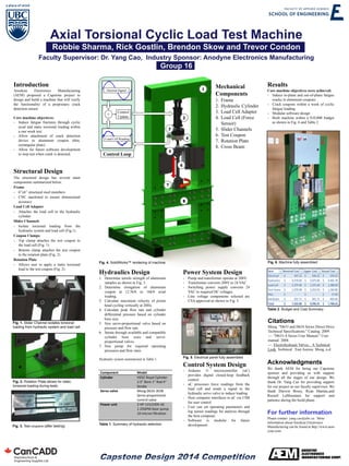
Axial Torsional Cyclic Load Test Machine
Robbie Sharma, Rick Gostlin, Brendon Skow and Trevor Condon
Faculty Supervisor: Dr. Yang Cao, Industry Sponsor: Anodyne Electronics Manufacturing
Group 16
Fig. 1. Slider Channel isolates torsional
loading from hydraulic system and load cell.
Mechanical
Components
1. Frame
2. Hydraulic Cylinder
3. Load Cell Adapter
4. Load Cell (Force
Sensor)
5. Slider Channels
6. Test Coupon
7. Rotation Plate
8. Cross Beam
For further information
Please contact yang.cao@ubc.ca. More
information about Anodyne Electronics
Manufacturing can be found at http://www.aem-
corp.com/
Fig. 3. Test coupons (after testing)
Hydraulics Design
1. Determine tensile strength of aluminum
samples as shown in Fig. 3.
2. Determine elongation of aluminum
coupon at 12.5kN to 16kN axial
loading.
3. Calculate maximum velocity of piston
head cycling vertically at 20Hz.
4. Calculate peak flow rate and cylinder
differential pressure based on cylinder
bore size.
5. Size servo-proportional valve based on
pressure and flow rate.
6. Iterate through available and compatible
cylinder bore sizes and servo-
proportional valves.
7. Size pump for required operating
pressures and flow rates.
Hydraulic system summarized in Table 1.
Power System Design
- Pump and transformer operate at 208V.
- Transformer converts 208V to 24 VAC
- Switching power supply converts 24
VAC to required DC voltages.
- Line voltage components selected are
CSA approved as shown in Fig. 5
Table 1. Summary of hydraulic selection
Fig. 5. Electrical panel fully assembled
Fig. 2. Rotation Plate allows for static
torsional loading during tests.
Control
Update
+
Load Cell Reading
Desired Signal
Control System Design
- Arduino © microcontroller (uC)
provides digital closed-loop feedback
control
- uC processes force readings from the
load cell and sends a signal to the
hydraulic servo valve to induce loading.
- Host computer interfaces to uC via USB
for user control
- User can set operating parameters and
log sensor readings for analysis through
the host computer.
- Software is modular for future
development
Control Loop
Fig. 4. SolidWorks™ rendering of machine
Table 2. Budget and Cost Summary
Fig. 6. Machine fully assembled
Item Nominal Cost UpperCost Actual Cost
Electrical 347.13$ 436.15$ 270.55$
Hydraulics 4,270.66$ 5,673.06$ 4,465.78$
Load cell 1,375.40$ 1,375.40$ 1,388.90$
Test frame 1,070.98$ 2,010.59$ 1,160.80$
Misc -$ -$ 17.00$
Hardware 501.71$ 501.71$ 405.60$
Total 7,565.88$ 9,996.91$ 7,708.63$
Citations
Moog. "D633 and D634 Series Direct Drive
Technical Specifications." Catalog. 2009.
—. "D633-A Series User Manual." User
manual. 2008.
—. Electrohydraulc Valves... A Technical
Look. Technical . East Aurora: Moog, n.d.
Component Model
Cylinder H25C Royal Cylinder
2.5” Bore 1” Rod 4”
Stroke
Servo valve Moog D633-303B
Servo-proportional
control valve
Power unit 2 HP 115/230V AC
1.25GPM Gear pump
10 micron filtration
More Related Content

Similar to AEM Poster

Electric_Drives_FinalProj
Electric_Drives_FinalProjElectric_Drives_FinalProj
Electric_Drives_FinalProjSpencer Minder
 
SRM_Journal_RS2015
SRM_Journal_RS2015SRM_Journal_RS2015
SRM_Journal_RS2015Aniket Ray
 
Classification of electric motors
Classification of electric motors Classification of electric motors
Classification of electric motors Sudhanshu Tripathi
 
WPT FinalProgressReport
WPT FinalProgressReportWPT FinalProgressReport
WPT FinalProgressReportNadeem Qandeel
 
Fabrication and Analysis of Fatigue Testing Machine
Fabrication and Analysis of Fatigue Testing MachineFabrication and Analysis of Fatigue Testing Machine
Fabrication and Analysis of Fatigue Testing Machinetheijes
 
IRJET- Design of Hybrid Boat using Microcontroller at mega 328
IRJET-  	  Design of Hybrid Boat using Microcontroller at mega 328IRJET-  	  Design of Hybrid Boat using Microcontroller at mega 328
IRJET- Design of Hybrid Boat using Microcontroller at mega 328IRJET Journal
 
EME 185 Poster
EME 185 PosterEME 185 Poster
EME 185 Postertonygom
 
IRJET- Multilevel Object Sorting System using PLC Controller
IRJET-  	  Multilevel Object Sorting System using PLC ControllerIRJET-  	  Multilevel Object Sorting System using PLC Controller
IRJET- Multilevel Object Sorting System using PLC ControllerIRJET Journal
 
Presentation final 4.29
Presentation final 4.29Presentation final 4.29
Presentation final 4.29Xueyin Shi
 
Electronic system for testing tensile strength of foundry sand
Electronic system for testing tensile strength of foundry sandElectronic system for testing tensile strength of foundry sand
Electronic system for testing tensile strength of foundry sandeSAT Publishing House
 
BHEL summer training .pptx
BHEL summer training .pptxBHEL summer training .pptx
BHEL summer training .pptxIishii
 
Yizhe_Liu_Resume_11092016
Yizhe_Liu_Resume_11092016Yizhe_Liu_Resume_11092016
Yizhe_Liu_Resume_11092016Yizhe Liu
 
IRJET- Design and Fabrication of Steering System using Servo Motors
IRJET- Design and Fabrication of Steering System using Servo MotorsIRJET- Design and Fabrication of Steering System using Servo Motors
IRJET- Design and Fabrication of Steering System using Servo MotorsIRJET Journal
 
IRJET- Auto Earth System for HV Test Set Up for Transformer in Applicatio...
IRJET-  	  Auto Earth System for HV Test Set Up for Transformer in Applicatio...IRJET-  	  Auto Earth System for HV Test Set Up for Transformer in Applicatio...
IRJET- Auto Earth System for HV Test Set Up for Transformer in Applicatio...IRJET Journal
 
vss102_lewis_2015_o
vss102_lewis_2015_ovss102_lewis_2015_o
vss102_lewis_2015_oAllan Lewis
 
Medical Device Grade Wireless Charger Poster - Vitali Tikhomolov
Medical Device Grade Wireless Charger Poster - Vitali TikhomolovMedical Device Grade Wireless Charger Poster - Vitali Tikhomolov
Medical Device Grade Wireless Charger Poster - Vitali TikhomolovVitali Tikhomolov
 
AN IMPROVED ELECTRICAL PANEL FOR DRIVING THE MAIN TABLE OF VERTICAL TURNING L...
AN IMPROVED ELECTRICAL PANEL FOR DRIVING THE MAIN TABLE OF VERTICAL TURNING L...AN IMPROVED ELECTRICAL PANEL FOR DRIVING THE MAIN TABLE OF VERTICAL TURNING L...
AN IMPROVED ELECTRICAL PANEL FOR DRIVING THE MAIN TABLE OF VERTICAL TURNING L...IRJET Journal
 

Similar to AEM Poster (20)

Electric Motorbike
Electric MotorbikeElectric Motorbike
Electric Motorbike
 
Electric_Drives_FinalProj
Electric_Drives_FinalProjElectric_Drives_FinalProj
Electric_Drives_FinalProj
 
SRM_Journal_RS2015
SRM_Journal_RS2015SRM_Journal_RS2015
SRM_Journal_RS2015
 
SRMAUV Journal
SRMAUV JournalSRMAUV Journal
SRMAUV Journal
 
Classification of electric motors
Classification of electric motors Classification of electric motors
Classification of electric motors
 
WPT FinalProgressReport
WPT FinalProgressReportWPT FinalProgressReport
WPT FinalProgressReport
 
Fabrication and Analysis of Fatigue Testing Machine
Fabrication and Analysis of Fatigue Testing MachineFabrication and Analysis of Fatigue Testing Machine
Fabrication and Analysis of Fatigue Testing Machine
 
IRJET- Design of Hybrid Boat using Microcontroller at mega 328
IRJET-  	  Design of Hybrid Boat using Microcontroller at mega 328IRJET-  	  Design of Hybrid Boat using Microcontroller at mega 328
IRJET- Design of Hybrid Boat using Microcontroller at mega 328
 
EME 185 Poster
EME 185 PosterEME 185 Poster
EME 185 Poster
 
IRJET- Multilevel Object Sorting System using PLC Controller
IRJET-  	  Multilevel Object Sorting System using PLC ControllerIRJET-  	  Multilevel Object Sorting System using PLC Controller
IRJET- Multilevel Object Sorting System using PLC Controller
 
Presentation final 4.29
Presentation final 4.29Presentation final 4.29
Presentation final 4.29
 
Electronic system for testing tensile strength of foundry sand
Electronic system for testing tensile strength of foundry sandElectronic system for testing tensile strength of foundry sand
Electronic system for testing tensile strength of foundry sand
 
BHEL summer training .pptx
BHEL summer training .pptxBHEL summer training .pptx
BHEL summer training .pptx
 
Yizhe_Liu_Resume_11092016
Yizhe_Liu_Resume_11092016Yizhe_Liu_Resume_11092016
Yizhe_Liu_Resume_11092016
 
IRJET- Design and Fabrication of Steering System using Servo Motors
IRJET- Design and Fabrication of Steering System using Servo MotorsIRJET- Design and Fabrication of Steering System using Servo Motors
IRJET- Design and Fabrication of Steering System using Servo Motors
 
IRJET- Auto Earth System for HV Test Set Up for Transformer in Applicatio...
IRJET-  	  Auto Earth System for HV Test Set Up for Transformer in Applicatio...IRJET-  	  Auto Earth System for HV Test Set Up for Transformer in Applicatio...
IRJET- Auto Earth System for HV Test Set Up for Transformer in Applicatio...
 
vss102_lewis_2015_o
vss102_lewis_2015_ovss102_lewis_2015_o
vss102_lewis_2015_o
 
WorkReportDRAFT
WorkReportDRAFTWorkReportDRAFT
WorkReportDRAFT
 
Medical Device Grade Wireless Charger Poster - Vitali Tikhomolov
Medical Device Grade Wireless Charger Poster - Vitali TikhomolovMedical Device Grade Wireless Charger Poster - Vitali Tikhomolov
Medical Device Grade Wireless Charger Poster - Vitali Tikhomolov
 
AN IMPROVED ELECTRICAL PANEL FOR DRIVING THE MAIN TABLE OF VERTICAL TURNING L...
AN IMPROVED ELECTRICAL PANEL FOR DRIVING THE MAIN TABLE OF VERTICAL TURNING L...AN IMPROVED ELECTRICAL PANEL FOR DRIVING THE MAIN TABLE OF VERTICAL TURNING L...
AN IMPROVED ELECTRICAL PANEL FOR DRIVING THE MAIN TABLE OF VERTICAL TURNING L...
 

AEM Poster

  • 1. Acknowledgments We thank AEM for being our Capstone sponsor and providing us with support through all the stages of our design. We thank Dr. Yang Cao for providing support for our project as our faculty supervisor. We thank Durwin Bossy, Ryan Mantau,and Russell LaMountain for support and patience during the build phase. Introduction Anodyne Electronics Manufacturing (AEM) proposed a Capstone project to design and build a machine that will verify the functionality of a proprietary crack detection sensor. Core machine objectives: - Induce fatigue fractures through cyclic axial and static torsional loading within a one week test. - Allow attachment of crack detection device to aluminum coupon (thin, rectangular plate). - Allow for future software development to stop test when crack is detected. Structural Design The structural design has several main components summarized below. Frame - 6”x6” structural steel members - CNC machined to ensure dimensional accuracy. Load Cell Adapter - Attaches the load cell to the hydraulic cylinder Slider Channels - Isolate torsional loading from the hydraulic system and load cell (Fig.1) Coupon Clamps: - Top clamp attaches the test coupon to the load cell (Fig. 1) - Bottom clamp attaches the test coupon to the rotation plate (Fig. 2) Rotation Plate - Allows user to apply a static torsional load to the test coupon (Fig. 2) Results Core machine objectives were achieved: - Induce in-plane and out-of-plane fatigue cracks in aluminum coupons - Crack coupons within a week of cyclic fatigue loading - Modular software design - Built machine within a $10,000 budget as shown in Fig. 6 and Table 2 Axial Torsional Cyclic Load Test Machine Robbie Sharma, Rick Gostlin, Brendon Skow and Trevor Condon Faculty Supervisor: Dr. Yang Cao, Industry Sponsor: Anodyne Electronics Manufacturing Group 16 Fig. 1. Slider Channel isolates torsional loading from hydraulic system and load cell. Mechanical Components 1. Frame 2. Hydraulic Cylinder 3. Load Cell Adapter 4. Load Cell (Force Sensor) 5. Slider Channels 6. Test Coupon 7. Rotation Plate 8. Cross Beam For further information Please contact yang.cao@ubc.ca. More information about Anodyne Electronics Manufacturing can be found at http://www.aem- corp.com/ Fig. 3. Test coupons (after testing) Hydraulics Design 1. Determine tensile strength of aluminum samples as shown in Fig. 3. 2. Determine elongation of aluminum coupon at 12.5kN to 16kN axial loading. 3. Calculate maximum velocity of piston head cycling vertically at 20Hz. 4. Calculate peak flow rate and cylinder differential pressure based on cylinder bore size. 5. Size servo-proportional valve based on pressure and flow rate. 6. Iterate through available and compatible cylinder bore sizes and servo- proportional valves. 7. Size pump for required operating pressures and flow rates. Hydraulic system summarized in Table 1. Power System Design - Pump and transformer operate at 208V. - Transformer converts 208V to 24 VAC - Switching power supply converts 24 VAC to required DC voltages. - Line voltage components selected are CSA approved as shown in Fig. 5 Table 1. Summary of hydraulic selection Fig. 5. Electrical panel fully assembled Fig. 2. Rotation Plate allows for static torsional loading during tests. Control Update + Load Cell Reading Desired Signal Control System Design - Arduino © microcontroller (uC) provides digital closed-loop feedback control - uC processes force readings from the load cell and sends a signal to the hydraulic servo valve to induce loading. - Host computer interfaces to uC via USB for user control - User can set operating parameters and log sensor readings for analysis through the host computer. - Software is modular for future development Control Loop Fig. 4. SolidWorks™ rendering of machine Table 2. Budget and Cost Summary Fig. 6. Machine fully assembled Item Nominal Cost UpperCost Actual Cost Electrical 347.13$ 436.15$ 270.55$ Hydraulics 4,270.66$ 5,673.06$ 4,465.78$ Load cell 1,375.40$ 1,375.40$ 1,388.90$ Test frame 1,070.98$ 2,010.59$ 1,160.80$ Misc -$ -$ 17.00$ Hardware 501.71$ 501.71$ 405.60$ Total 7,565.88$ 9,996.91$ 7,708.63$ Citations Moog. "D633 and D634 Series Direct Drive Technical Specifications." Catalog. 2009. —. "D633-A Series User Manual." User manual. 2008. —. Electrohydraulc Valves... A Technical Look. Technical . East Aurora: Moog, n.d. Component Model Cylinder H25C Royal Cylinder 2.5” Bore 1” Rod 4” Stroke Servo valve Moog D633-303B Servo-proportional control valve Power unit 2 HP 115/230V AC 1.25GPM Gear pump 10 micron filtration