This document provides an overview, intended audience, and related documentation for the Intel Ethernet Adapters and Devices User Guide. It describes installing Intel network adapters, connecting the appropriate network cables, and supported operating systems. Compatibility notes specify requirements for certain adapters and note the last releases supporting some Windows and Linux versions.


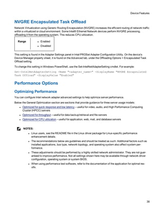
![Device Features
19
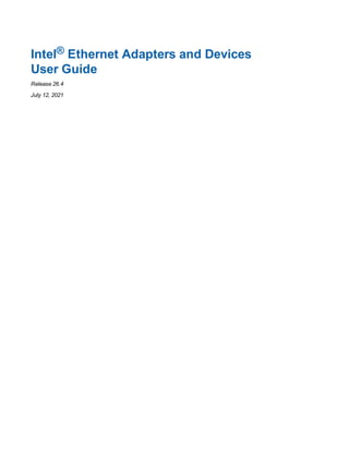
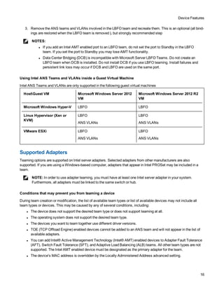
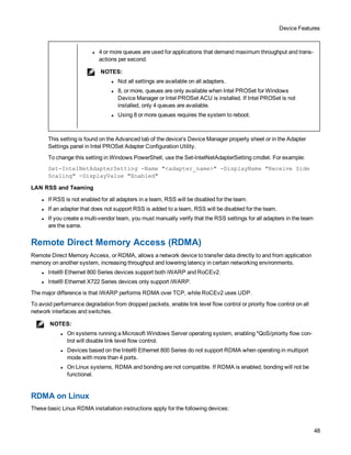
Renaming a Team
Use the Set-IntelNetTeam cmdlet. For example
Set-IntelNetTeam -TeamName "<team_name>" -NewTeamName "<new_team_name>"
Removing a Team
Use the Remove-IntelNetTeam cmdlet. For example
Remove-IntelNetTeamMember -Name "<adapter_name>"
NOTE: If you defined a VLAN or QoS Prioritization on an adapter joining a team, you may have to redefine it
when it is returned to a stand-alone mode.
Specifying a Preferred Primary or Secondary Adapter
Use the Set-IntelNetTeam cmdlet. For example
Set-IntelNetTeam -TeamName "Team 1" -PrimaryAdapterName "<adapter1_name>" -Sec-
ondaryAdapterName "<adapter2_name>"
Configuring Teams with Intel PROSet ACU
Creating a Team with Intel PROSet ACU
1. Launch the Intel PROSet ACU.
2. Select an adapter to start the team.
3. Click the Teaming/VLANs tab.
4. In the Teaming panel, click Create Team.
5. Select the adapters to include in the team, then click Next.
6. Type a name for the team.
7. Select the teaming mode, then click Next.
8. [Optional] Designate Primary and Secondary adapters for the team.
9. Click Finish.
Changing Which Adapters Are In a Team
1. Launch the Intel PROSet ACU.
2. Select the team you wish to modify.
3. In the Team Members panel, click Modify Members.
4. Select the adapters that will be members of the team
5. Click Apply Changes.
Renaming a Team
1. Launch the Intel PROSet ACU.
2. Select the team you wish to modify.
3. In the Team Information panel, type a new team name..
4. Click Apply Changes.](https://image.slidesharecdn.com/adapteruserguide26-220604120044-1eb315ba/85/adapter_user_guide_26-4-pdf-19-320.jpg)


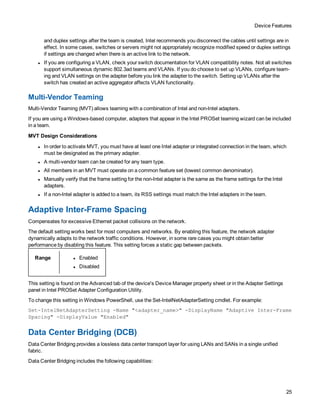


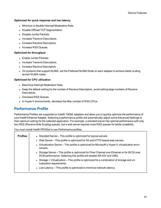


![Microsoft* Windows* Driver and Software Installation and Configuration
66
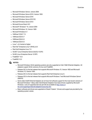
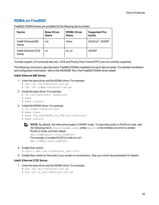
Parameter Definition
"1", create or update the "Intel® PROSet Adapter Configuration Utility" desktop shortcut.
If this parameter is not specified, the shortcut will only be created or updated if it was created
by a previous software installation.
RDMA_
ROUTING
RDMA routing
"0", do not install RDMA routing.
"1", install RDMA routing.
IWARP_
FIREWALL
Installs the iWARP firewall rule. For more information see iWARP (Internet Wide Area
RDMA Protocol) section.
"0", do not install iWARP firewall rule.
"1", install iWARP firewall rule. If "1" is selected, the following parameters are allowed in
addition to IWARP_FIREWALL.
l IWARP_FIREWALL_DOMAIN [0|1] - Applies firewall rule to corporate domains.
l IWARP_FIREWALL_PUBLIC [0|1] - Applies firewall rule to public networks
l IWARP_FIREWALL_PRIVATE [0|1] - Applies firewall rule to private networks
FORCE "0", check that the installed device supports a feature (iSCSI) and only install the feature if
such a device is found.
"1", install the specified features regardless of the presence of supporting devices.
/q[r|n] /q --- silent install options
r Reduced GUI Install (only displays critical warning messages)
n Silent install
/l[i|w|e|a] /l --- log file option for PROSet installation. Following are log switches:
i log status messages.
w log non-fatal warnings.
e log error messages.
a log the start of all actions.
/uninstall
/x
Uninstall Intel PROSet and drivers.](https://image.slidesharecdn.com/adapteruserguide26-220604120044-1eb315ba/85/adapter_user_guide_26-4-pdf-66-320.jpg)

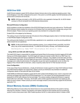
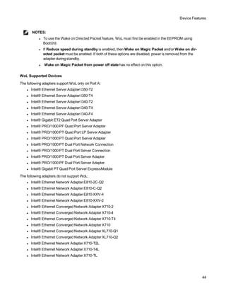
![Microsoft* Windows* Driver and Software Installation and Configuration
69
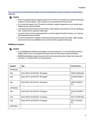
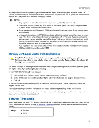
NOTES:
l You must have Administrator privileges to run scripts. If you do not have Administrator privileges, you
will not receive an error, the script just will not run.
l Only adapter settings are saved (these include Intel ANS teaming and VLANs). The adapter's driver
is not saved.
l Restore using the script only once. Restoring multiple times may result in unstable configuration.
l Intel® PROSet must be installed for the SaveRestore.ps1 script to run.
l For systems running a 64-bit OS, be sure to run the 64-bit version of Windows PowerShell, not the
32-bit (x86) version, when running the SaveRestore.ps1 script.
Command Line Syntax
SaveRestore.ps1 –Action save|restore [-ConfigPath] [-BDF]
SaveRestore.ps1 has the following command line options:
Option Description
-Action Required. Valid values: save | restore.
The save option saves adapter and team settings that have been changed from the default
settings. When you restore with the resulting file, any settings not contained in the file are
assumed to be the default.
The restore option restores the settings.
-ConfigPath Optional. Specifies the path and filename of the main configuration save file. If not specified, it is
the script path and default filename (saved_config.txt).
-BDF Optional. Default configuration file names are saved_config.txt and Saved_StaticIP.txt.
If you specify -BDF during a restore, the script attempts to restore the configuration based on the
PCI Bus:Device:Function:Segment values of the saved configuration. If you removed, added, or
moved a NIC to a different slot, this may result in the script applying the saved settings to a
different device.
NOTES:
l If the restore system is not identical to the saved system, the script may not restore any set-
tings when the -BDF option is specified.
l Virtual Function devices do not support the -BDF option.
Examples
Save Example
To save the adapter settings to a file on a removable media device, do the following.
1. Open a Windows PowerShell Prompt.
2. Navigate to the directory where SaveRestore.ps1 is located (generally c:Program FilesIntelWired Net-
workingPROSET).
3. Type the following:
SaveRestore.ps1 –Action Save –ConfigPath e:settings.txt](https://image.slidesharecdn.com/adapteruserguide26-220604120044-1eb315ba/85/adapter_user_guide_26-4-pdf-69-320.jpg)


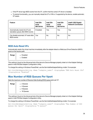
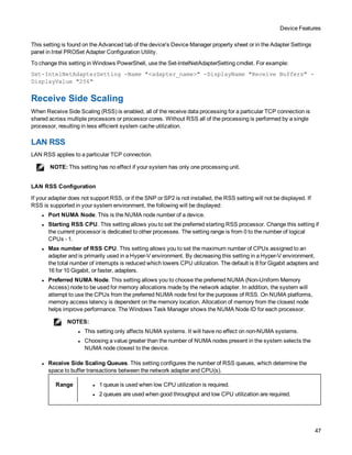
![Remote Boot
76
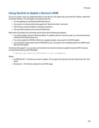
FA 03004000 B X X 2 2 Intel(R) Network Connection
3.0.00
/e3000e2.efi
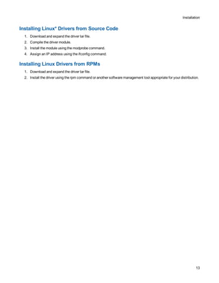
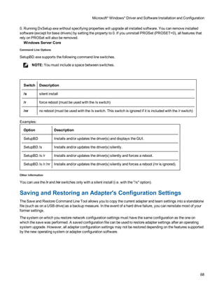
A network boot option will appear in the boot options menu when the UEFI PXE network stack and Intel UEFI network
driver have been loaded. Selecting this
boot option will initiate a PXE network boot.
Configuring UEFI Network Stack for TCP/UDP/MTFTP
An IP-based network stack is available to applications requiring IP-based network protocols such as TCP, UDP, or
MTFTP. The following UEFI network drivers must be built into the UEFI platform implementation to enable this stack:
SNP (Simple Network Protocol), MNP (Managed Network Protocol), ARP, DHCP4, IPv4, ip4config, TCPv4, UDPv4,
and MTFTPv4. These drivers will show up in the UEFI "drivers" command output if they are included in the platform
UEFI implementation:
DRV VERSION TYPE CFG DIAG #D #C DRIVER NAME IMAGE
NAME
F5 00000010 D - - 2 - IP4 CONFIG Network Service
Driver
Ip4Config
F7 00000010 D - - 2 - Simple Network Protocol Driver SNP
F8 00000010 D - - 2 - ARP Network Service Driver Arp
F9 00000010 D - - 2 - Tcp Network Service Driver Tcp4
FA 00000010 D - - 2 - IP4 Network Service Driver Ip4
FB 00000010 D - - 2 - DHCP Protocol Driver Dhcp4
FC 00000010 D - - 6 - UDP Network Service Driver Udp4
FD 00000010 D - - 2 - MTFTP4 Network Service Mtftp4
FE 00000010 B - - 2 6 MNP Network Service Driver /mnp.efi
FF 03099900 B X X 2 2 Intel(R) Network Connection
3.0.00
/e3000e2.efi
The ifconfig UEFI shell command must be used to configure each network interface. Running "ifconfig -?" from the
UEFI shell will display usage instructions for ifconfig.
Unloading the UEFI Network Driver
To unload a network driver from memory the UEFI "unload" command is used. The syntax for using the unload
command is as follows: "unload [driver handle]", where driver handle is the number assigned to the driver in the far left
column of the "drivers" output screen.](https://image.slidesharecdn.com/adapteruserguide26-220604120044-1eb315ba/85/adapter_user_guide_26-4-pdf-76-320.jpg)
![Remote Boot
77
Force Speed and Duplex
The UEFI network driver supports forced speed and duplex capability. The force speed and duplex menu can be
accessed with UEFI shell command "drvcfg":
drvcfg -s [driver handle] [control handle]
The following speed and duplex configurations can be selected:
l Autonegotiate (recommended)
l 100 Mbps, full duplex
l 100 Mbps, half duplex
l 10 Mbps, full duplex
l 10 Mbps, half duplex
The speed and duplex setting selected must match the speed and duplex setting of the connecting network port. A
speed and duplex mismatch between ports will result in dropped packets and poor network performance. It is
recommended to set all ports on a network to autonegotiate. Connected ports must be set to autonegotiate in order to
establish a 1 gigabit per second connection.
Fiber-optic and 10 gigabit ethernet adapters do not support forced speed and duplex.
Diagnostic Capability
The UEFI network driver features built in hardware diagnostic tests. The diagnostic tests are called with the UEFI
shell drvdiag command.
drvdiag -s -Performs a basic hardware register test.
drvdiag -e -Performs an internal loopback transmit and receive test.
UEFI Known Issues
Long Initialization Times
Long initialization times observed with Intel’s UEFI driver are caused when the UNDI.Initialize command is called with
the PXE_OPFLAGS_INITIALIZE_CABLE_DETECT flag set. In this case, UNDI.Initialize will try to detect the link
state.
If the port is connected and link is up, initialize will generally finish in about 3.5 seconds (the time needed to establish
link, dependent on link conditions, link speed and controller type) and returns PXE_STATFLAGS_COMMAND_
COMPLETE. If the port is disconnected (link is down), initialize will complete in about 5 seconds and return PXE_
STATFLAGS_INIIALIZED_NO_MEDIA (driver initializes hardware then waits for link and timeouts when link is not
establish in 5 seconds).
When UNDI.Initialize is called with PXE_OPFLAGS_INITIALIZE_DO_NOT_DETECT_CABLE the function will not
try to detect link status and will take less than 1 second to complete.
The behavior of UNDI.Initialize is described in UEFI specs 2.3.1: Initializing the network device will take up to four
seconds for most network devices and in some extreme cases (usually poor cables) up to twenty seconds. Control
will not be returned to the caller and the COMMAND_COMPLETE status flag will not be set until the adapter is ready
to transmit.](https://image.slidesharecdn.com/adapteruserguide26-220604120044-1eb315ba/85/adapter_user_guide_26-4-pdf-77-320.jpg)


![Known Issues
138
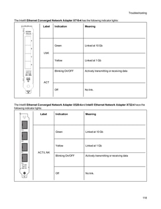
Supported SFP or SFP+ Module Not Recognized by the System
If you try to install an unsupported module, the port may no longer install any subsequent modules, regardless of
whether the module is supported or not. The port will show a yellow bang under Windows Device Manager and an
event id 49 (unsupported module) will be added to the system log when this issue occurs. To resolve this issue, the
system must be completely powered off.
Windows Known Issues
Unable to shutdown virtual machine
Multiple VF failover events may leave a VM in an unstable state. You may not be able to shutdown the VM. Rebooting
the host will resolve the issue.
Traffic does not transmit through VXLAN tunnel
On a system running Microsoft Windows Server 2016, traffic may fail to transmit through a VXLAN tunnel. Enabling
Transmit Checksum Offloads for the appropriate traffic type will resolve the issue. For example, set "TCP Checksum
Offload (IPv4)" to "TX Enabled" or "RX & TX Enabled"
hv_vmbus probe error on a Linux guest in a Windows Server system
On a system running Microsoft Windows Server 2019 or Windows Server 2016 on the host and Linux in the VF, you
may see an "hv_vmbus: probe failed for device X" error in dmesg after you change a vSwitch from VMQ to SRIOV.
This is due to a known timing issue in the operating system. There is no functionality loss, and the VF will successfully
start after a few failed probes.
Incomplete branding string displayed in the event log
Some branding strings are too long to be displayed fully in the event log. In these cases, the branding string will be
truncated and the port's PCI Bus/Device/Function are appended to the string. For example: Intel(R) Ethernet
Converged Network Ad... [129,0,1].
PcieLinkSpeed is Unknown
When you install an Intel® Ethernet 800 Series device in a PCI Gen 4 slot, the operating system may report
PcieLinkSpeed as Unknown. This does not affect the operation of the device.
Windows guest OSs on a Linux host may not pass traffic across VLANs
The VF is not aware of the VLAN configuration if you use LBFO to configure VLANs in a Windows guest. VLANs
configured using LBFO on a VF driver may result in failure to pass traffic. You must use Windows Hyper-V on the host
to configure VLANs on a Windows guest.
Intermittent Link Loss and Degraded Performance at High Stress Can Occur on Windows Server 2012 Sys-
tems
In a Windows Server 2012-based system with multi-core processors, possible intermittent link loss and degraded
performance at high stress may occur due to incorrect RSS processor assignments. More information and a Microsoft
hotfix are available at: http://support.microsoft.com/kb/2846837.
Virtual machine loses link on a Microsoft Windows Server 2012 R2 system
On a Microsoft Windows Server 2012 R2 system with VMQ enabled, if you change the BaseRssProcessor setting,
then install Microsoft Hyper-V and create one or more virtual machines, the virtual machines may lose link. Installing
the April 2014 update rollup for Windows RT 8.1, Windows 8.1, and Windows Server 2012 R2 (2919355) and hotfix
3031598 will resolve the issue. See http://support2.microsoft.com/kb/2919355 and
http://support2.microsoft.com/kb/3031598 for details.](https://image.slidesharecdn.com/adapteruserguide26-220604120044-1eb315ba/85/adapter_user_guide_26-4-pdf-138-320.jpg)


![Attack surfaces and attack tress[inform]](https://cdn.slidesharecdn.com/ss_thumbnails/lecture03-260108015941-a4dee53b-thumbnail.jpg?width=640&height=640&fit=bounds)


