⚫Sensors are fundamentalbuilding blocks of IoT networks
⚫Sensors are the foundational elements found in
smart objects—the “things” in the Internet of Things
⚫Smart objects are any physical objects that contain
embedded technology to sense and/or interact
with their environment in a meaningful way by
being interconnected and enabling
communication among themselves or an
external agent.
3.
SENSORS, ACTUATORS, ANDSMART
OBJECTS
⚫A sensor: It senses
⚫More specifically, a sensor measures some physical
quantity and converts that measurement reading
into a digital representation.
⚫That digital representation is typically passed to
another device for transformation into useful data
that can be consumed by intelligent devices or
humans
⚫Sensors are not limited to human-like sensory data.
⚫They are able to provide an extremely wide spectrum of
rich and diverse measurement data with far greater
precision than human senses
4.
Categorie
s
⚫Active or passive:
⚫Sensorscan be categorized based on whether they produce
an energy output and typically require an external
power supply (active) or
⚫Whether they simply receive energy and typically require
no external power supply (passive).
⚫Invasive or non-invasive:
⚫Sensors can be categorized based on whether a sensor is
part of the environment it is measuring (invasive) or
⚫External to it (non-invasive).
5.
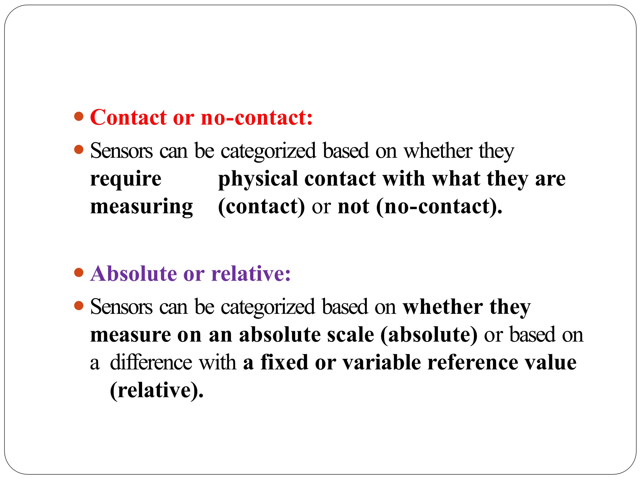
⚫Contact or no-contact:
⚫Sensorscan be categorized based on whether they
require physical contact with what they are
measuring (contact) or not (no-contact).
⚫Absolute or relative:
⚫Sensors can be categorized based on whether they
measure on an absolute scale (absolute) or based on
a difference with a fixed or variable reference value
(relative).
6.
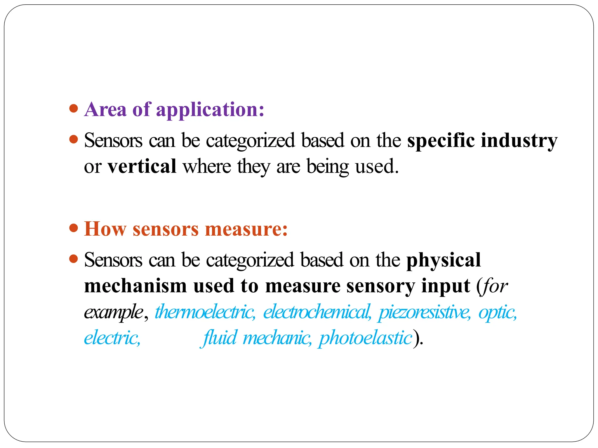
⚫Area of application:
⚫Sensorscan be categorized based on the specific industry
or vertical where they are being used.
⚫How sensors measure:
⚫Sensors can be categorized based on the physical
mechanism used to measure sensory input (for
example, thermoelectric, electrochemical, piezoresistive, optic,
electric, fluid mechanic, photoelastic).
7.
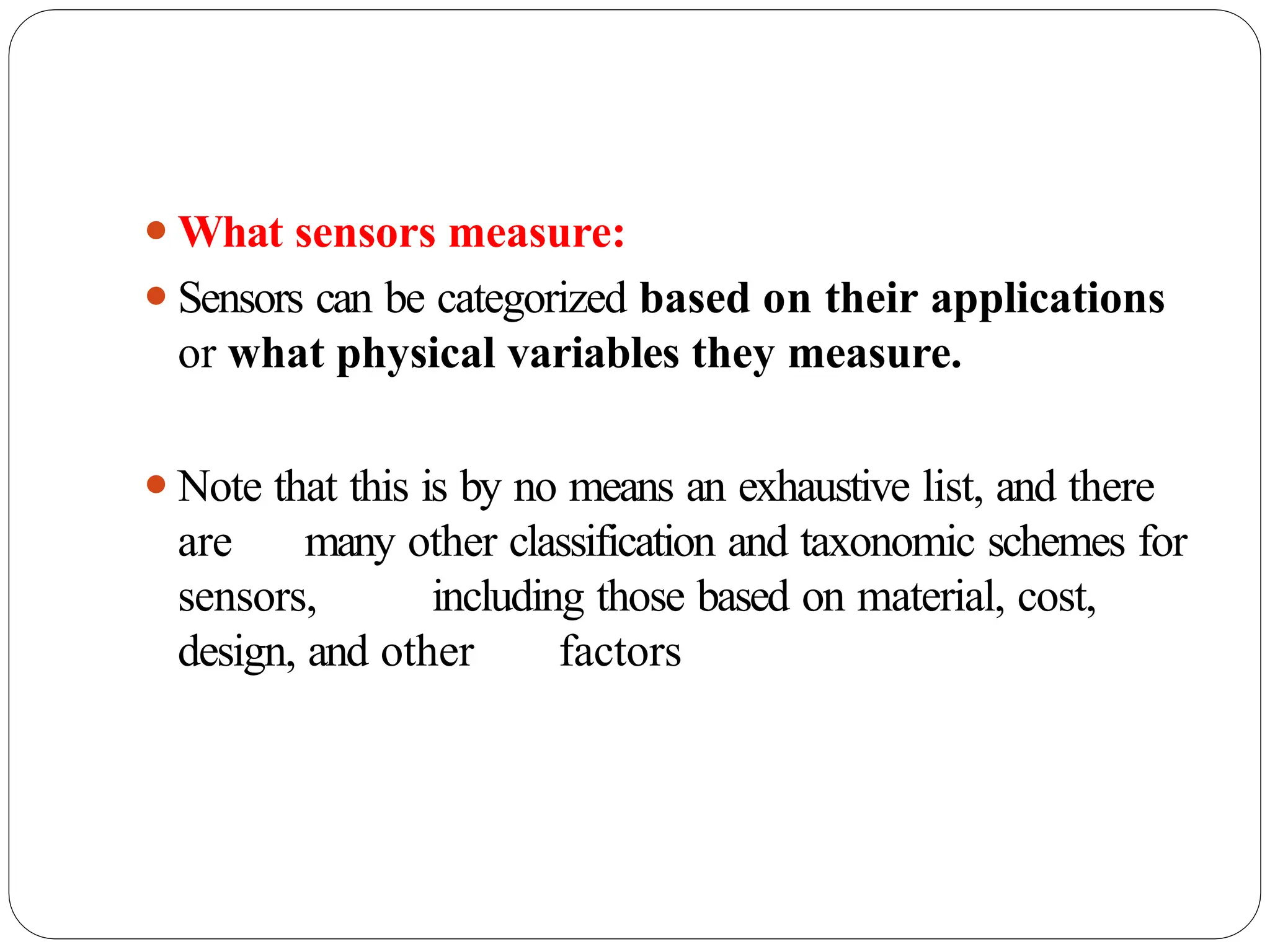
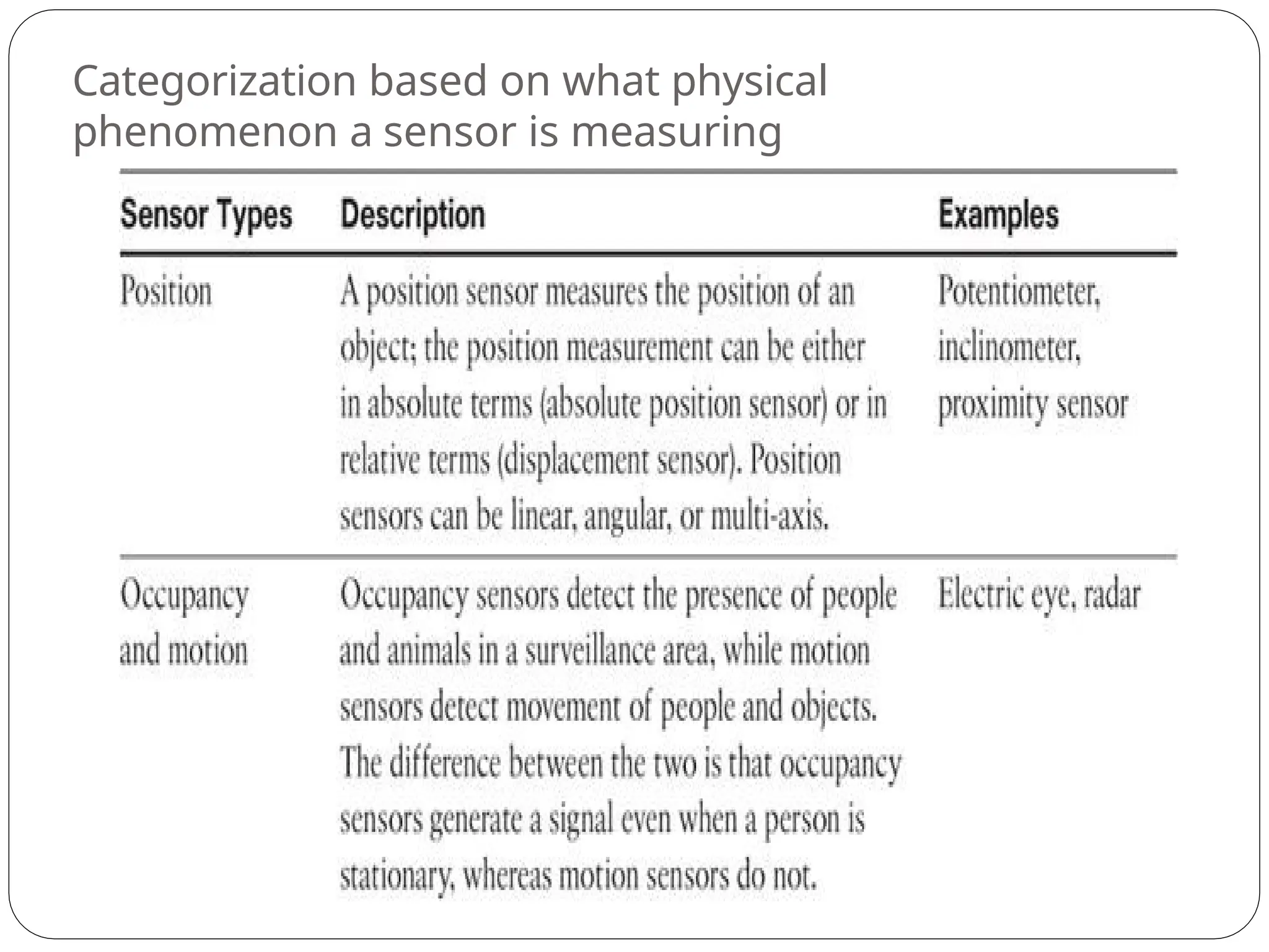
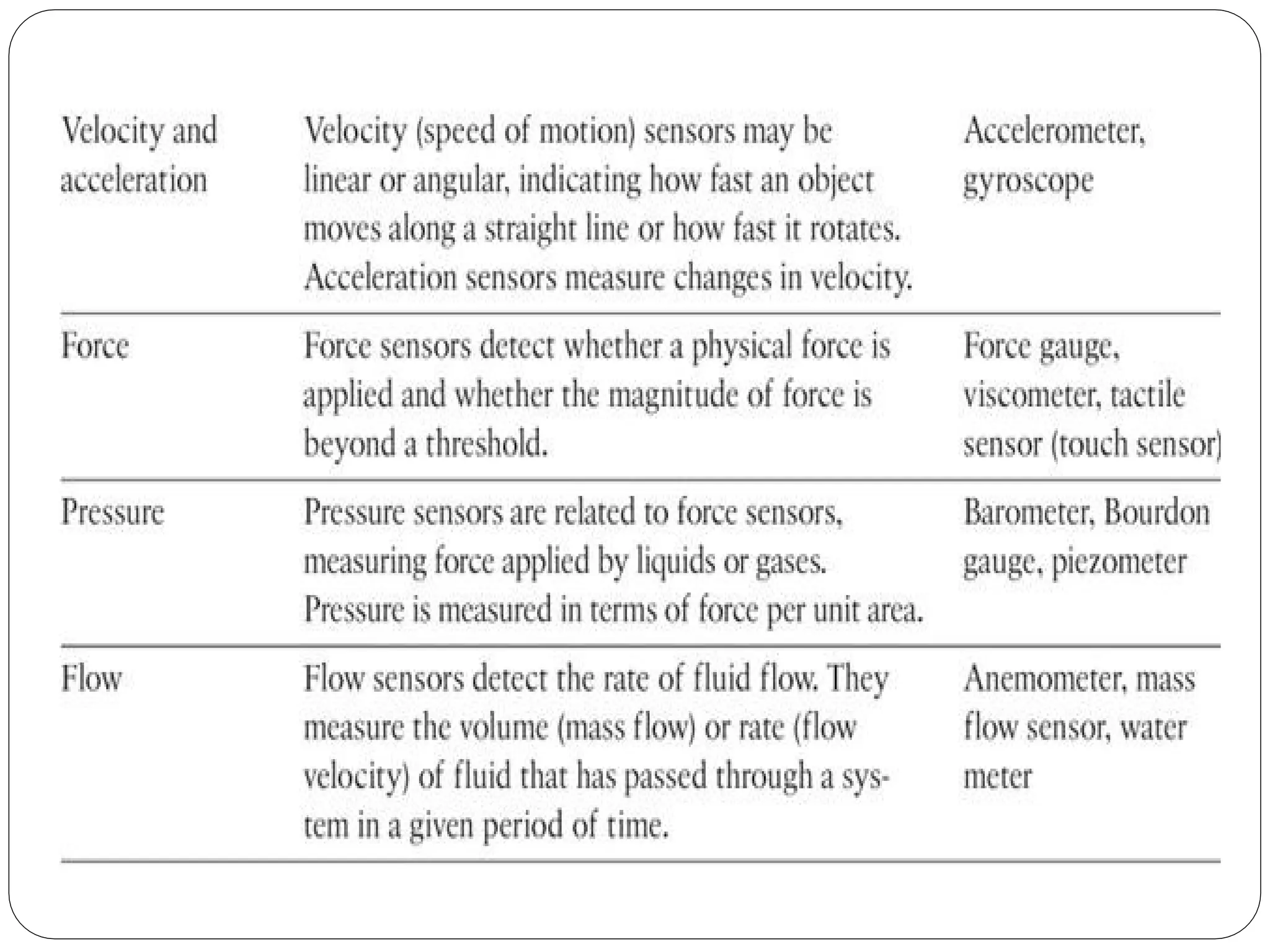
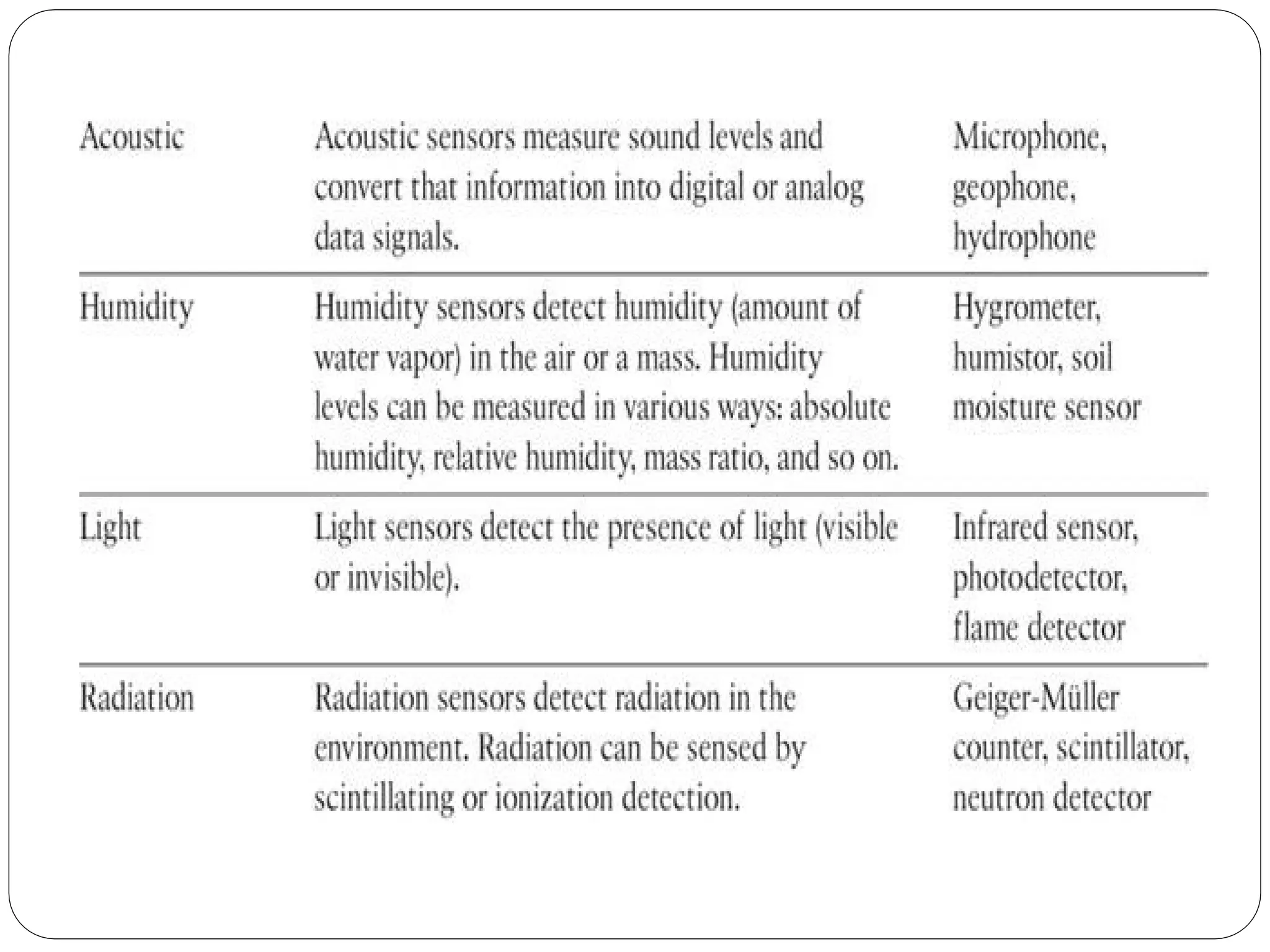
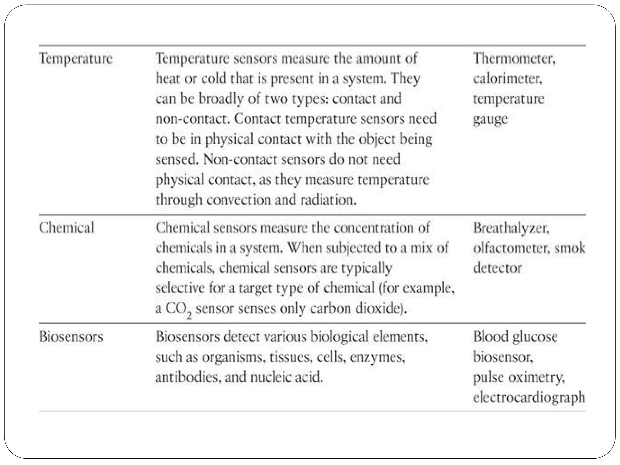
⚫What sensors measure:
⚫Sensorscan be categorized based on their applications
or what physical variables they measure.
⚫Note that this is by no means an exhaustive list, and there
are many other classification and taxonomic schemes for
sensors, including those based on material, cost,
design, and other factors
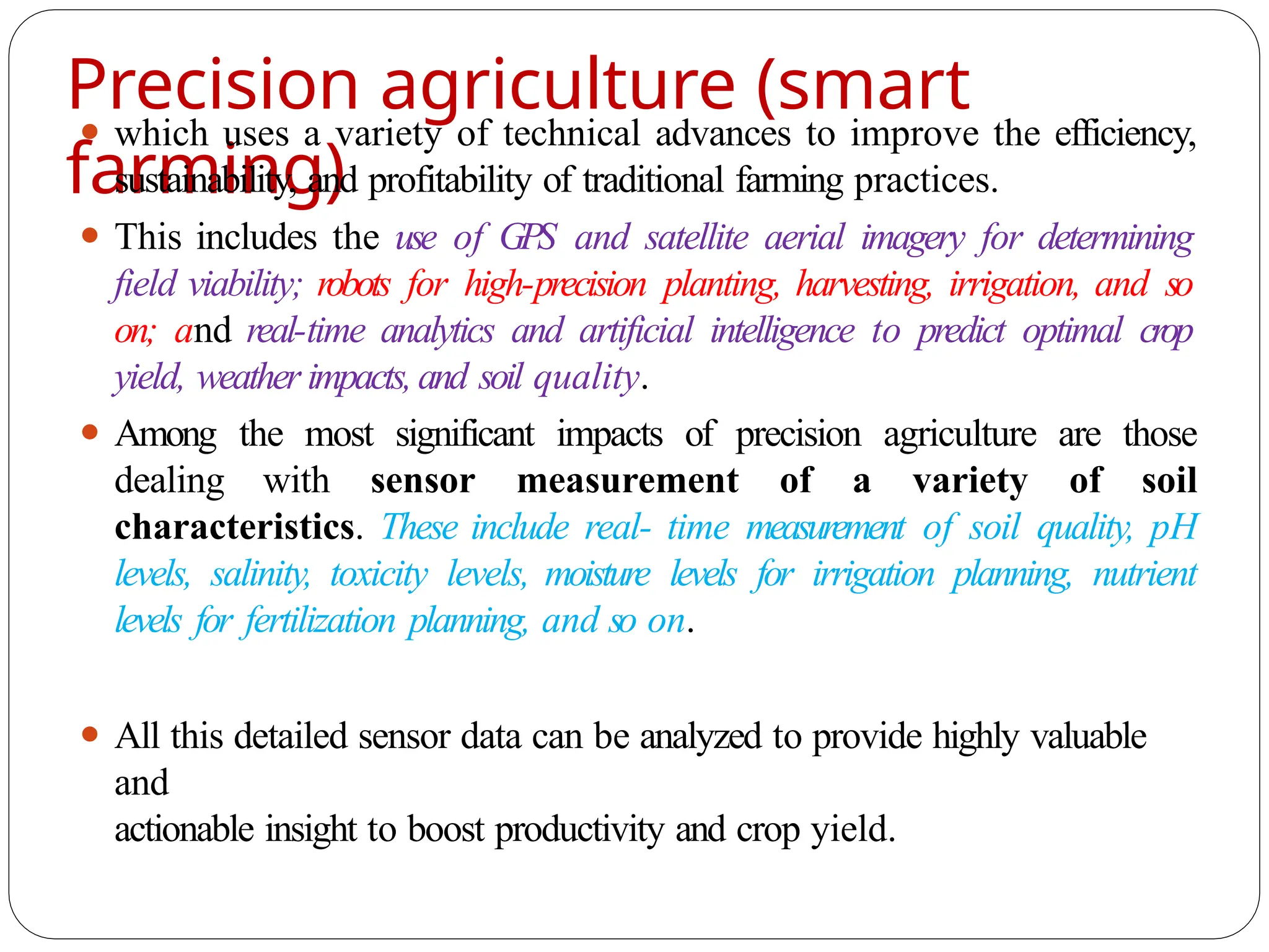
Precision agriculture (smart
farming)
⚫which uses a variety of technical advances to improve the efficiency,
sustainability, and profitability of traditional farming practices.
⚫ This includes the use of GPS and satellite aerial imagery for determining
field viability; robots for high-precision planting, harvesting, irrigation, and so
on; and real-time analytics and artificial intelligence to predict optimal crop
yield, weather impacts,and soil quality.
⚫ Among the most significant impacts of precision agriculture are those
dealing with sensor measurement of a variety of soil
characteristics. These include real- time measurement of soil quality, pH
levels, salinity, toxicity levels, moisture levels for irrigation planning, nutrient
levels for fertilization planning, and so on.
⚫ All this detailed sensor data can be analyzed to provide highly valuable
and
actionable insight to boost productivity and crop yield.
13.
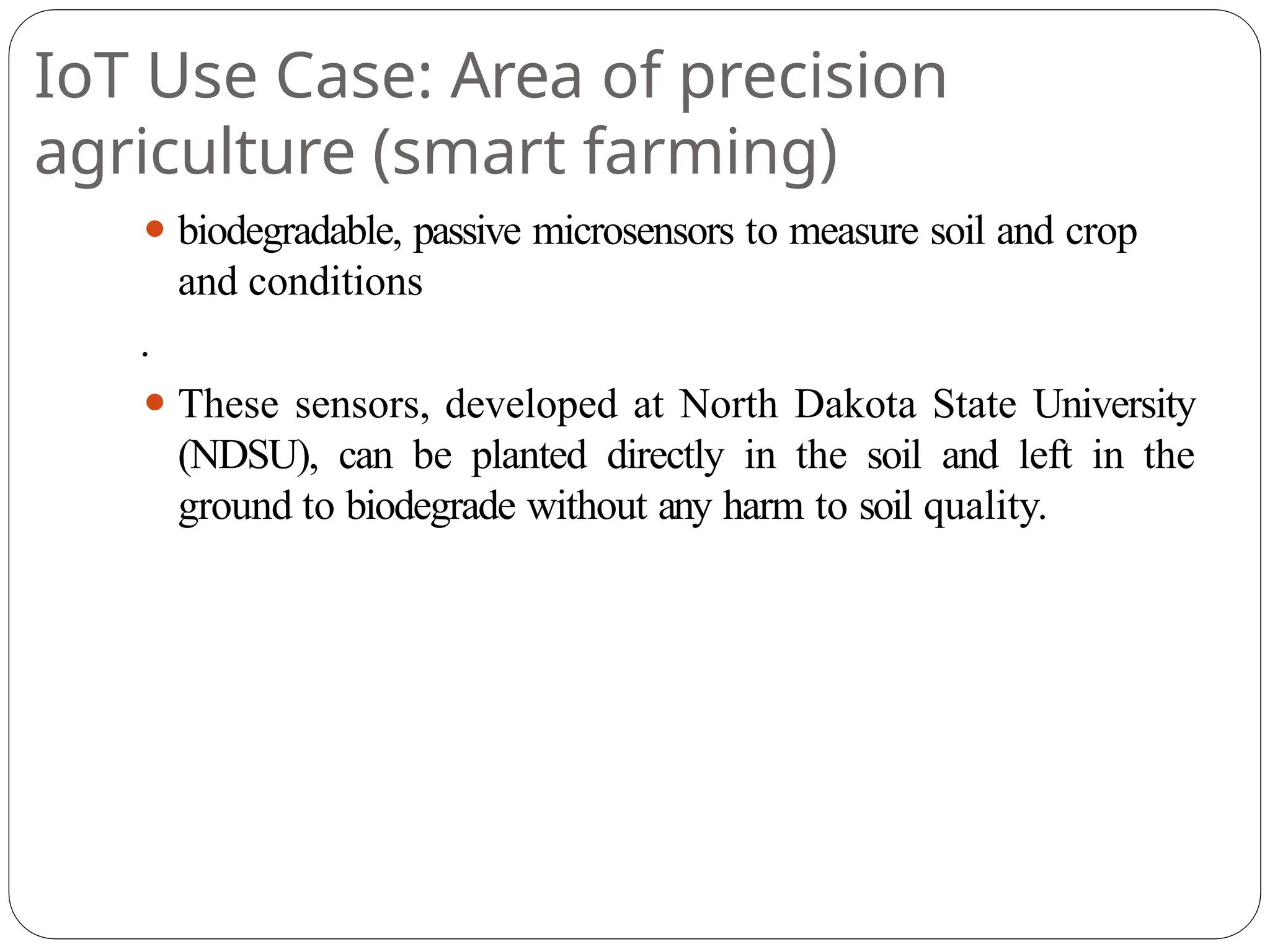
IoT Use Case:Area of precision
agriculture (smart farming)
⚫ biodegradable, passive microsensors to measure soil and crop
and conditions
.
⚫ These sensors, developed at North Dakota State University
(NDSU), can be planted directly in the soil and left in the
ground to biodegrade without any harm to soil quality.
Actuator
s
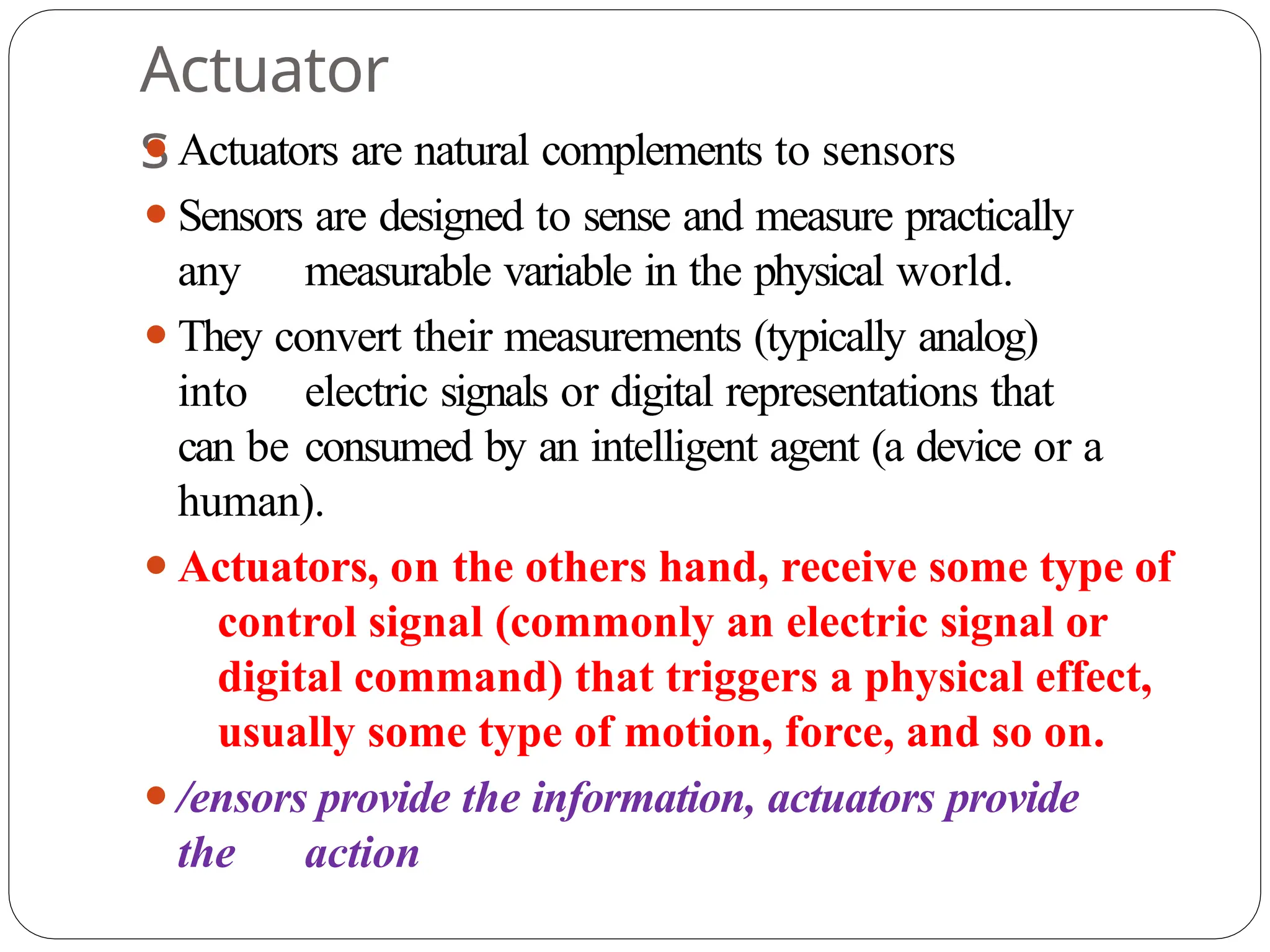
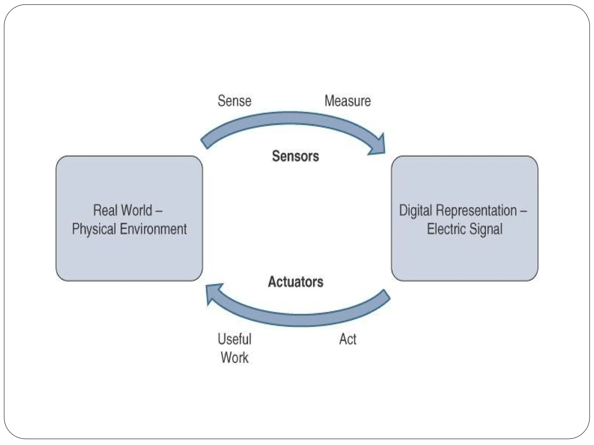
⚫Actuators are naturalcomplements to sensors
⚫Sensors are designed to sense and measure practically
any measurable variable in the physical world.
⚫They convert their measurements (typically analog)
into electric signals or digital representations that
can be consumed by an intelligent agent (a device or a
human).
⚫Actuators, on the others hand, receive some type of
control signal (commonly an electric signal or
digital command) that triggers a physical effect,
usually some type of motion, force, and so on.
⚫/ensors provide the information, actuators provide
the action
20.
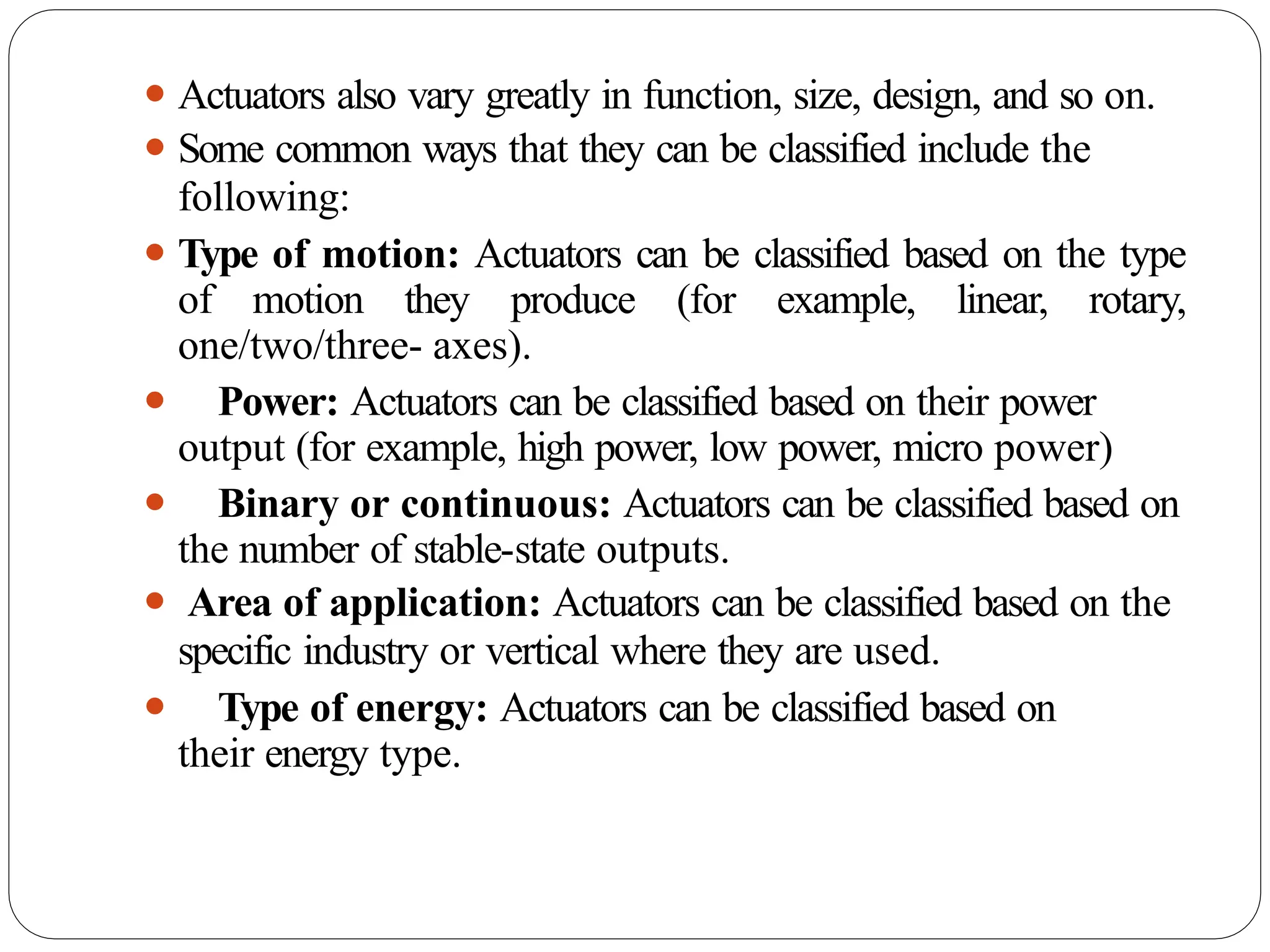
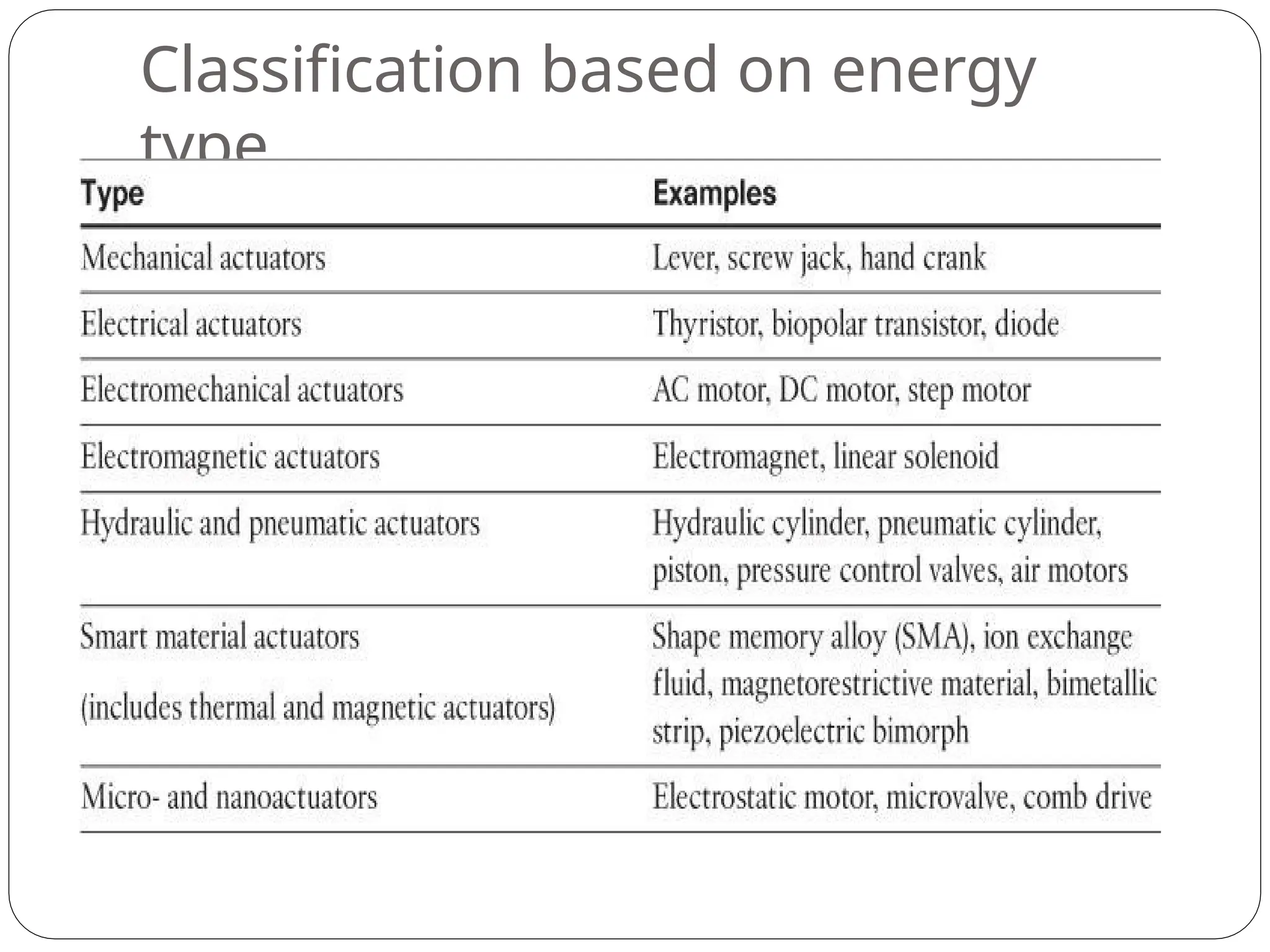
⚫ Actuators alsovary greatly in function, size, design, and so on.
⚫ Some common ways that they can be classified include the
following:
⚫ Type of motion: Actuators can be classified based on the type
of motion they produce (for example, linear, rotary,
one/two/three- axes).
⚫ Power: Actuators can be classified based on their power
output (for example, high power, low power, micro power)
⚫ Binary or continuous: Actuators can be classified based on
the number of stable-state outputs.
⚫ Area of application: Actuators can be classified based on the
specific industry or vertical where they are used.
⚫ Type of energy: Actuators can be classified based on
their energy type.
Micro-Electro-Mechanical Systems
(MEMS)
⚫ Interestingadvances in sensor and actuator technologies is in
how they are packaged and deployed.
⚫ Micro-electro-mechanical systems (MEMS), sometimes
simply referred to as micro-machines, can integrate and combine
electric and mechanical elements, such as sensors and actuators,
on a very small (millimeter or less) scale.
⚫ One of the keys to this technology is a
microfabrication technique that is similar to what is
used for microelectronicintegrated circuits.
⚫ This approach allows mass production at very low costs
23.
⚫ The combinationof tiny size, low cost, and the ability to
mass produce makes MEMS an attractive option for a huge
number of IoT applications.
⚫ MEMS devices have already been widely used in a variety
of different applications and can be found in very
familiar everyday devices.
⚫ For example, inkjet printers use micropump MEMS.
⚫ Smart phones also use MEMS technologies for things
like accelerometers and gyroscopes.
⚫ In fact, automobiles were among the first to
commercially introduce MEMS into the mass market,
with airbag accelerometers.
Smart Objects
⚫Smart objectsare, quite simply, the building blocks of IoT.
⚫They are what transform everyday objects into a
network of intelligent objects that are able to
learn from and interact with their
environment in a meaningful way
⚫The real power of smart objects in IoT comes from
being networked together rather than being isolated as
standalone objects
26.
⚫ If asensor is a standalone device that simply measures
the humidity of the soil, it is interesting and useful, but
it isn’t revolutionary
⚫ If that same sensor is connected as part of an
intelligent network that is able to coordinate
intelligently with actuators to trigger irrigation
systems as needed based on those sensor readings, we
have something far more powerful
⚫ Extending that even further, imagine that the coordinated
sensor/actuator set is intelligently interconnected with
other sensor/actuator sets to further coordinate
fertilization, pest control, and so on—and even
communicate with an intelligent backend to calculate crop
yield potential
27.
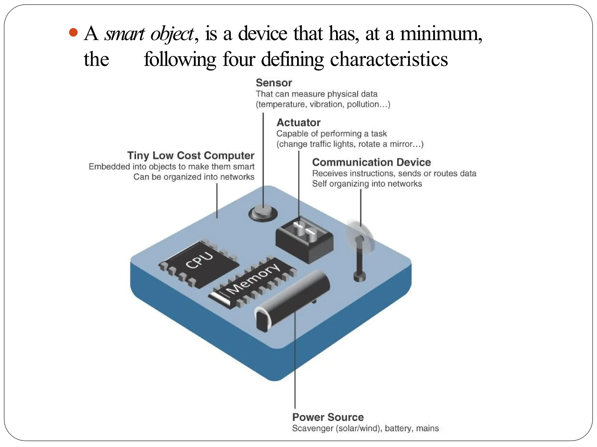
⚫A smart object,is a device that has, at a minimum,
the following four defining characteristics
28.
⚫Processing unit:
⚫Some typeof processing unit for
⚫Acquiring data,
⚫Processing and analyzing sensing
information received by the sensor(s),
⚫Coordinating control signals to any
actuators, and
⚫Controlling a variety of functions on the smart
object, including the communication and power
systems
⚫The most common is a microcontroller because of
its small form factor, flexibility, programming
simplicity, ubiquity, low power consumption, and
29.
⚫Sensor(s) and/or actuator(s):
⚫Asmart object is capable of interacting with the
physical world through sensors and actuators
⚫Communication device:
⚫The communication unit is responsible for connecting
a smart object with other smart objects and the
outside world (via the network).
⚫Communication devices for smart objects can be either
wired or wireless
30.
⚫Power source:
⚫Smart objectshave components that need to be powered.
⚫The most significant power consumption usually comes
from the communication unit of a smart object
31.
Trends in SmartObjects
⚫Size is decreasing
⚫Power consumption is decreasing
⚫Processing power is increasing
⚫Communication capabilities are improving
⚫Communication is being increasingly standardized
32.
SENSOR NETWORKS
⚫A sensor/actuatornetwork (SANET), is a network of
sensors that sense and measure their environment
and/or actuators that act on their environment
⚫The sensors and/or actuators in a SANET are capable
of communicating and cooperating
⚫Effective and well-coordinated communication and
cooperation is a prominent challenge, primarily because the
sensors and actuators in SANETs are diverse, heterogeneous,
and resource-constrained
33.
⚫SANETs offer highlycoordinated sensing and actuation
capabilities.
⚫Smart homes are a type of SANET that display this
coordination between distributed sensors and actuators
⚫For example, smart homes can have temperature sensors
that are strategically networked with heating, ventilation,
and air-conditioning (HVAC) actuators.
⚫When a sensor detects a specified temperature, this can
trigger an actuator to take action and heat or cool the
home as needed.
34.
⚫Advantages and disadvantagesthat a wireless-based
solution offers:
Advantages:
⚫ Greater deployment flexibility (especially in
extreme environments or hard-to-reach places)
⚫ Simpler scaling to a large number of nodes
⚫ Lower implementation costs
⚫ Easier long-term maintenance
⚫ Effortless introduction of new sensor/actuator
nodes
⚫ Better equipped to handle dynamic/rapid topology
changes
Disadvantages:
⚫ Potentially less secure (for example, hijacked access
points)
35.
Wireless Sensor Networks
(WSNs)
⚫Wirelesssensor networks are made up of wirelessly
connected smart objects, which are sometimes
referred to as motes.
⚫The fact that there is no infrastructure to consider
with WSNs is surely a powerful advantage for
flexible
deployments, but there are a variety of design
constraints to consider with these wirelessly connected
smart objects
37.
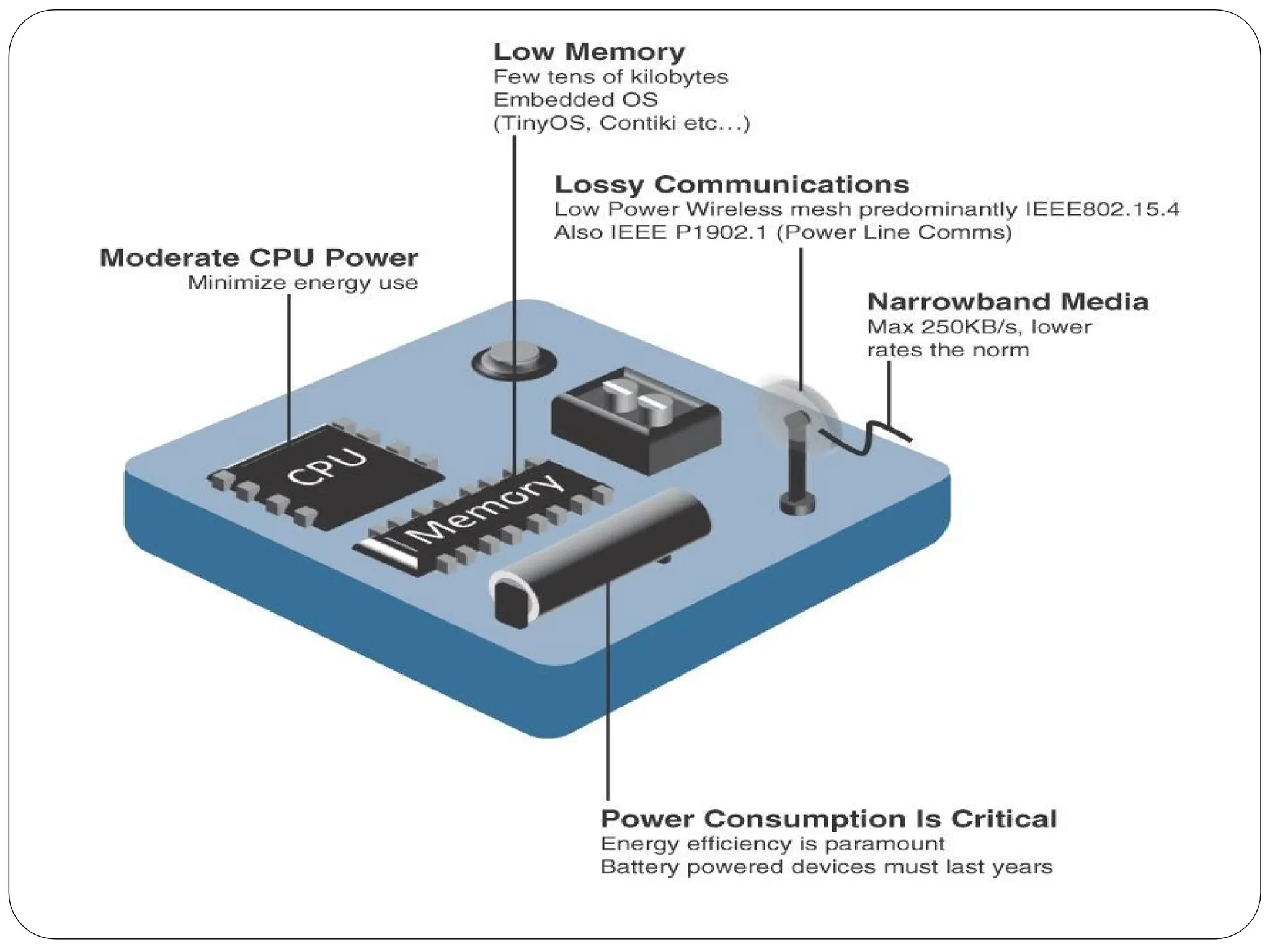
⚫ The followingare some of the most significant limitations
of the smart objects in WSNs:
⚫ Limited processing power
⚫ Limited memory
⚫ Lossy communication
⚫ Limited transmission speeds
⚫ Limited power
⚫Note
⚫Smart objects with limited processing, memory, power,
and so on are often referred to as constrained nodes.
38.
⚫These limitations greatlyinfluence how WSNs are
designed, deployed, and utilized.
⚫The fact that individual sensor nodes are typically so
limited is a reason that they are often deployed in
very large numbers.
⚫As the cost of sensor nodes continues to decline, the
ability to deploy highly redundant sensors becomes
increasingly feasible.
⚫Because many sensors are very inexpensive and
correspondingly inaccurate, the ability to deploy
smart objects redundantly allows for increased
accuracy
39.
⚫Such large numbersof sensors permit the
introduction of hierarchies of smart objects.
⚫ Such a hierarchy provides, among other
organizational advantages, the ability to aggregate
similar sensor readings from sensor nodes
that are in close proximity to each other
40.
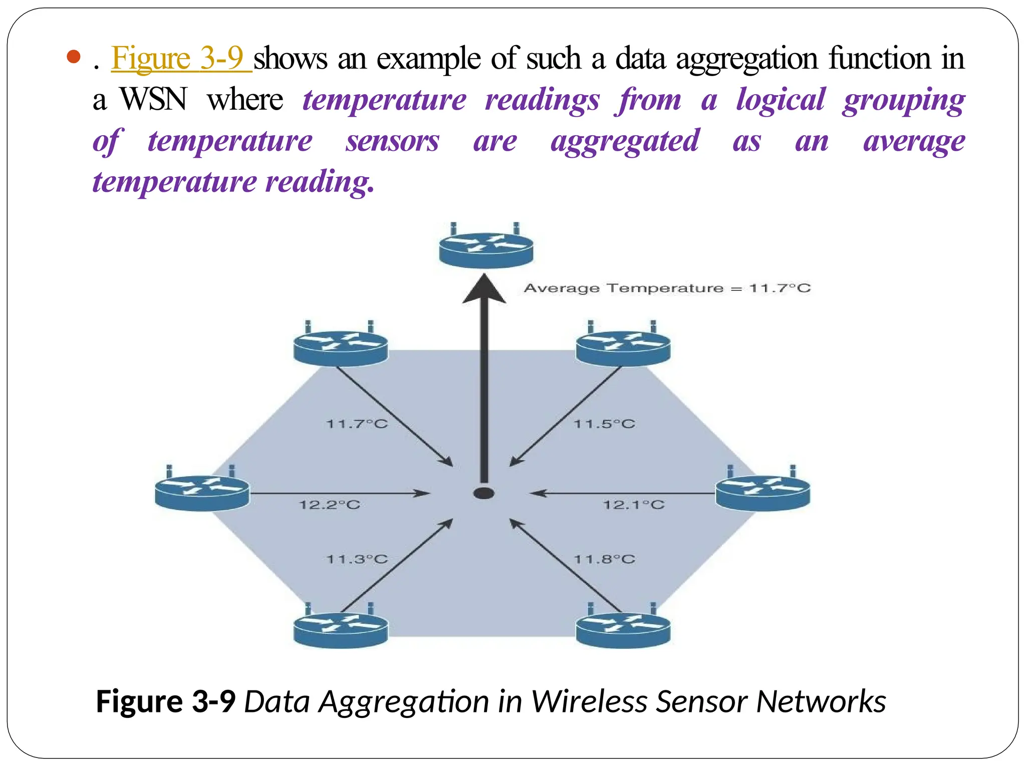
⚫ . Figure3-9 shows an example of such a data aggregation function in
a WSN where temperature readings from a logical grouping
of temperature sensors are aggregated as an average
temperature reading.
Figure 3-9 Data Aggregation in Wireless Sensor Networks
41.
⚫ These dataaggregation techniques are helpful in reducing the
amount of overall traffic (and energy) inW/Ns with very
large numbers of deployed smart objects.
⚫ This data aggregation at the network edges is where fog and
mist computing are critical IoT architectural elements
needed to deliver the scale and performance required by so
many IoT use cases
42.
⚫ Wirelessly connectedsmart objects generally have one of the
following two communication patterns:
⚫ Event-driven:
⚫ Transmission of sensory information is triggered only when a smart
object detects a particular event or predetermined threshold.
⚫ Periodic:
⚫ Transmission of sensory information occurs only at periodic
intervals.
⚫The decision of which of these communication schemes is used
depends greatly on the specific application
⚫For example: medical use cases
43.
⚫For example, insome medical use cases, sensors
periodically send postoperative vitals, such
as temperature or blood pressure readings.
In other medical use cases, the same blood
pressure or temperature readings are
triggered to be sent only when certain critically
low or high readings are measured.
44.
Communication Protocols for
WirelessSensor Networks
⚫ There are literally thousands of different types of sensors and actuators.
⚫ WSNs are becoming increasingly heterogeneous, with more
sophisticated interactions.
⚫ Any communication protocol must be able to scale to a large
number of nodes.
⚫ Likewise, when selecting a communication protocol, you must
carefully take into account the requirements of the specific
application and consider any trade-offs the communication
protocol offers between power consumption,
maximum
transmission speed, range, tolerance for packet loss,
topology optimization, security, and so on
45.
⚫ They mustalso enable, as needed, the overlay of autonomous
techniques (for example, self-organization, self-healing,
self- configuration)
⚫ Wireless sensor networks interact with their environment. Sensors
often produce large amounts of sensing and measurement data that
needs to be processed. This data can be processed locally by the
nodes of a WSN or across zero or more hierarchical levels in IoT
networks.
⚫ Communication protocols need to facilitate routing and
message handling for this data flow between sensor
nodes as well as from sensor nodes to optional gateways, edge
compute, or centralized cloud compute
46.
⚫ standardization ofcommunication protocols is a
complicated task.
⚫ While there isn’t a single protocol solution, there is
beginning to be some clear market convergence around
several key communication protocols.
47.
Connecting Smart Objects
⚫IoTdevices and sensors must be connected to the
network for their data to be utilized.
⚫In addition to the wide range of sensors, actuators, and
smart objects that make up IoT, there are also a number of
different protocols used to connect them
48.
COMMUNICATIONS CRITERIA
⚫The characteristicsand attributes you should
consider when selecting and dealing with
connecting smart objects
⚫Range
⚫Frequency Bands:
⚫Power Consumption:
⚫Topology
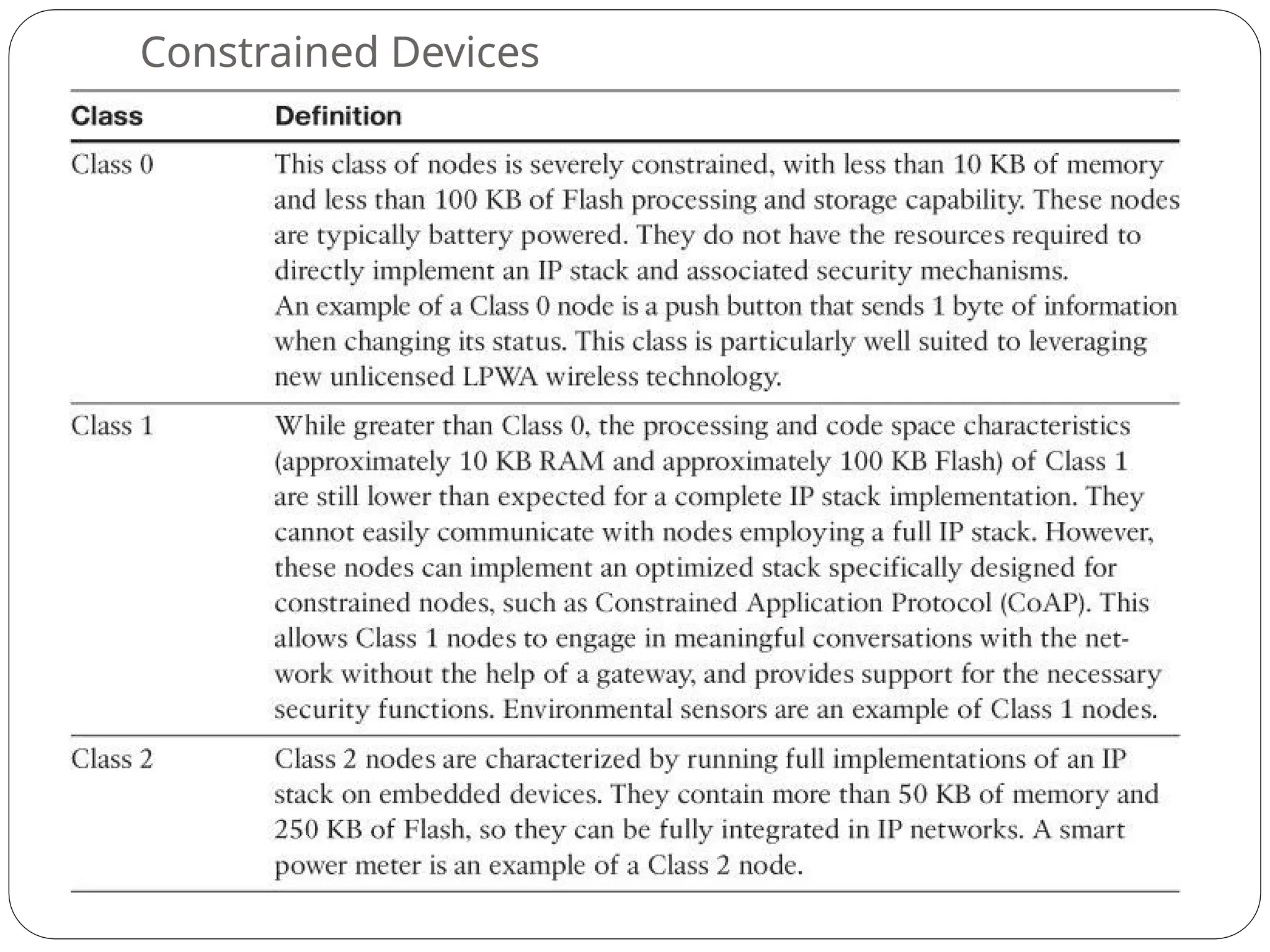
⚫Constrained Devices:
⚫Constrained-Node Networks:
49.
⚫Range
⚫How far doesthe signal need to be propagated?
⚫That is, what will be the area of coverage for a
selected wireless technology?
⚫Should indoor versus outdoor deployments be
differentiated?
51.
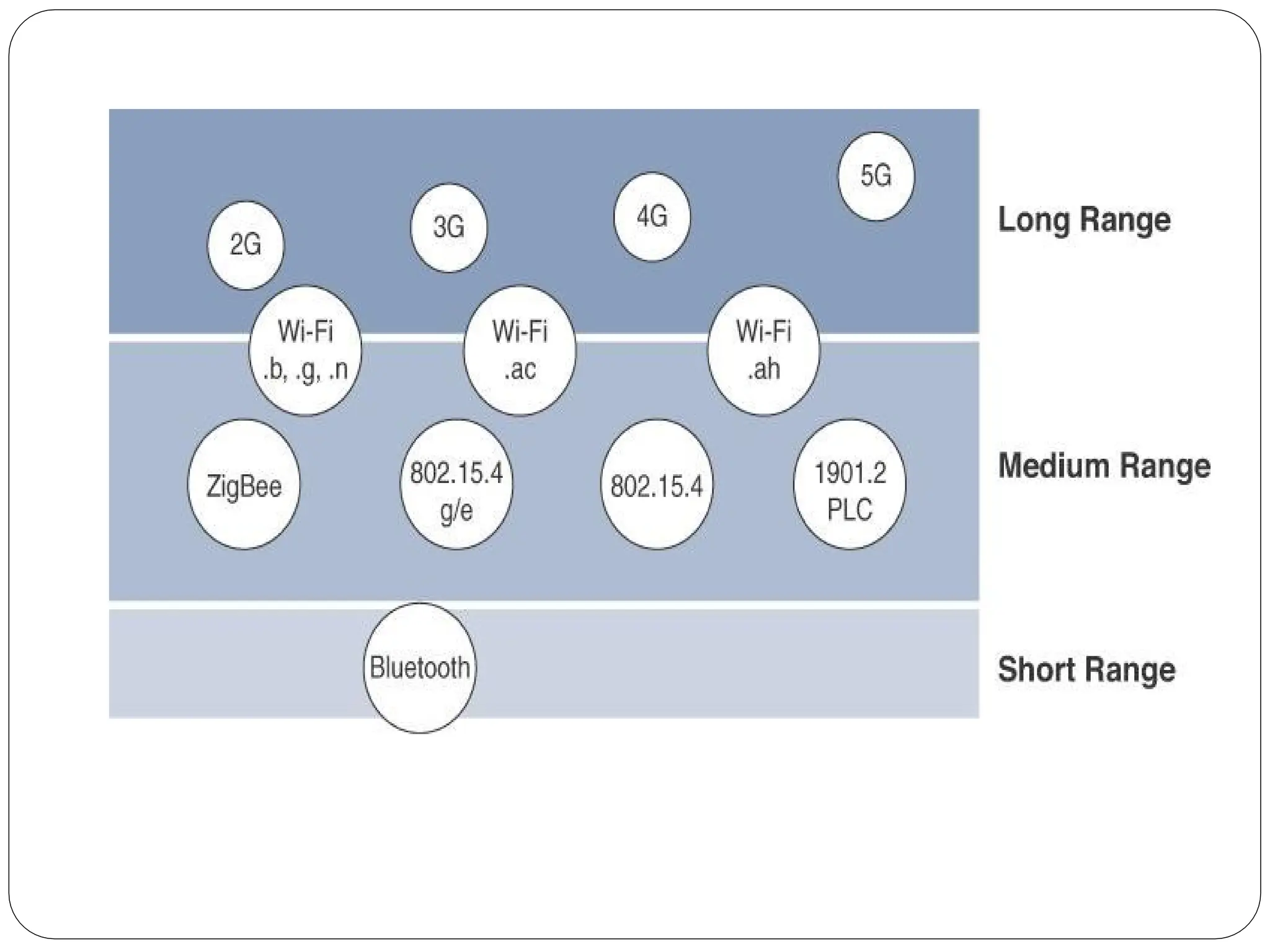
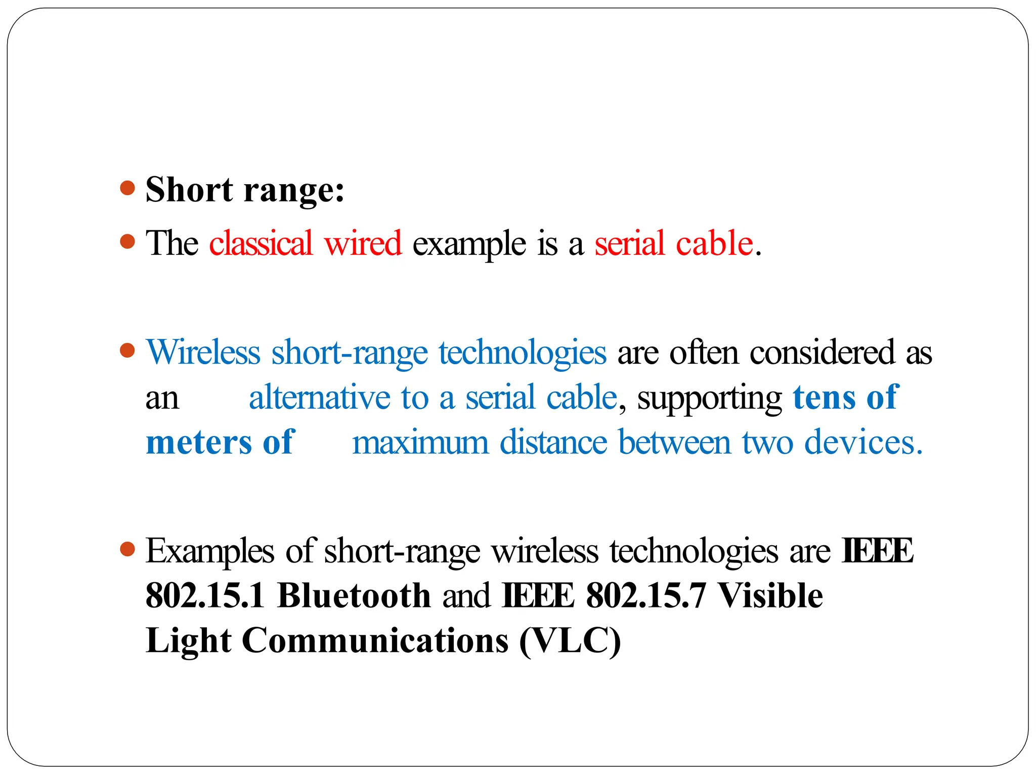
⚫Short range:
⚫The classicalwired example is a serial cable.
⚫Wireless short-range technologies are often considered as
an alternative to a serial cable, supporting tens of
meters of maximum distance between two devices.
⚫Examples of short-range wireless technologies are IEEE
802.15.1 Bluetooth and IEEE 802.15.7 Visible
Light Communications (VLC)
52.
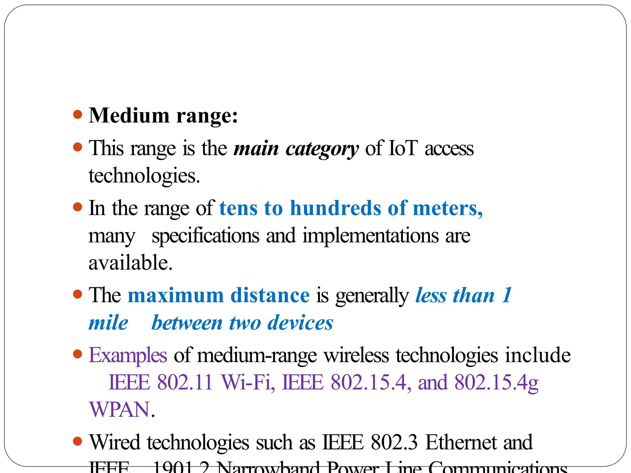
⚫Medium range:
⚫This rangeis the main category of IoT access
technologies.
⚫In the range of tens to hundreds of meters,
many specifications and implementations are
available.
⚫The maximum distance is generally less than 1
mile between two devices
⚫Examples of medium-range wireless technologies include
IEEE 802.11 Wi-Fi, IEEE 802.15.4, and 802.15.4g
WPAN.
⚫Wired technologies such as IEEE 802.3 Ethernet and
53.
⚫Long range:
⚫Distances greaterthan 1 mile between two devices
require long-range technologies.
⚫Wireless examples are cellular (2G, 3G, 4G) and some
applications of outdoor IEEE 802.11 Wi-Fi and Low-
Power Wide-Area (LPWA) technologies.
⚫LPW
A communications have the ability to communicate over a
large area without consuming much power. These
technologies are therefore ideal for battery-powered
IoT sensors
54.
⚫Frequency Bands
⚫Radio spectrumis regulated by countries and/or
organizations, such as the International
Telecommunication Union (ITU) and the Federal
Communications Commission (FCC).
⚫These groups define the regulations and
transmission requirements for various
frequency bands
⚫For example, portions of the spectrum are allocated to
types of telecommunications such as radio, television,
military, and so on.
55.
⚫Focusing on IoTaccess technologies, the frequency
bands leveraged by wireless communications are
split between licensed and unlicensed bands.
⚫Licensed spectrum is generally applicable to IoT
long- range access technologies
⚫In order to utilize licensed spectrum, users must
subscribe to services when connecting their IoT
devices
⚫In exchange for the subscription fee, the network operator
can guarantee the exclusivity of the frequency usage over
the target area and can therefore sell a better guarantee
of service.
56.
⚫ The ITUhas also defined unlicensed spectrum for the
industrial, scientific, and medical (ISM) portions of the radio
bands.
⚫ These frequencies are used in many communications
technologies for short-range devices (SRDs).
⚫ Unlicensed means that no guarantees or protections
are offered in the ISM bands for device
communications
⚫ ISM bands for IoT access
⚫ 2.4 GHz band as used by IEEE 802.11b/g/n Wi-Fi
⚫ IEEE 802.15.1 Bluetooth
⚫ IEEE 802.15.4 WPAN
57.
⚫Unlicensed spectrum isusually simpler to deploy
than licensed because it does not require a service
provider.
⚫However, it can suffer from more interference because
other devices may be competing for the same frequency
in a specific area
⚫The frequency of transmission directly impacts how a
signal propagates and its practical maximum range.
58.
Power Consumption
⚫Powered nodesand battery-powered nodes
⚫A powered node has a direct connection to a
power source, and communications are
usually not limited by power consumption criteria.
⚫However, ease of deployment of powered nodes is
limited by the availability of a power source,
which makes mobility more complex
⚫Battery-powered nodes bring much more flexibility
to IoT devices.
⚫These nodes are often classified by the required
lifetimes of their batteries.
59.
⚫For battery-
powered
nodes, IoTwireless
access
technologies must address the needs of low
power consumption and connectivity
⚫A new wireless environment known as Low-Power
Wide- Area (LPWA)
⚫Battery-powered nodes are often placed in a “sleep
mode”
to preserve battery life when not transmitting
⚫Wired IoT access technologies consisting of powered
nodes are not exempt from power optimization
60.
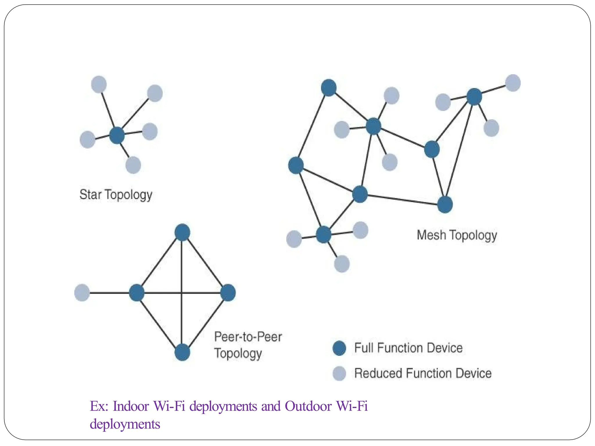
Topology
⚫Among the accesstechnologies available for connecting IoT
devices, three main topology schemes are dominant: star,
mesh, and peer-to-peer
⚫For long-range and short-range technologies, a star topology
is prevalent
⚫Star topologies utilize a single central base station or controller
to allow communications with endpoints
⚫For medium-range technologies, a star, peer-to-peer, or
mesh topology is common
⚫Peer-to-peer topologies allow any device to communicate
with any other device as long as they are in range of
each other
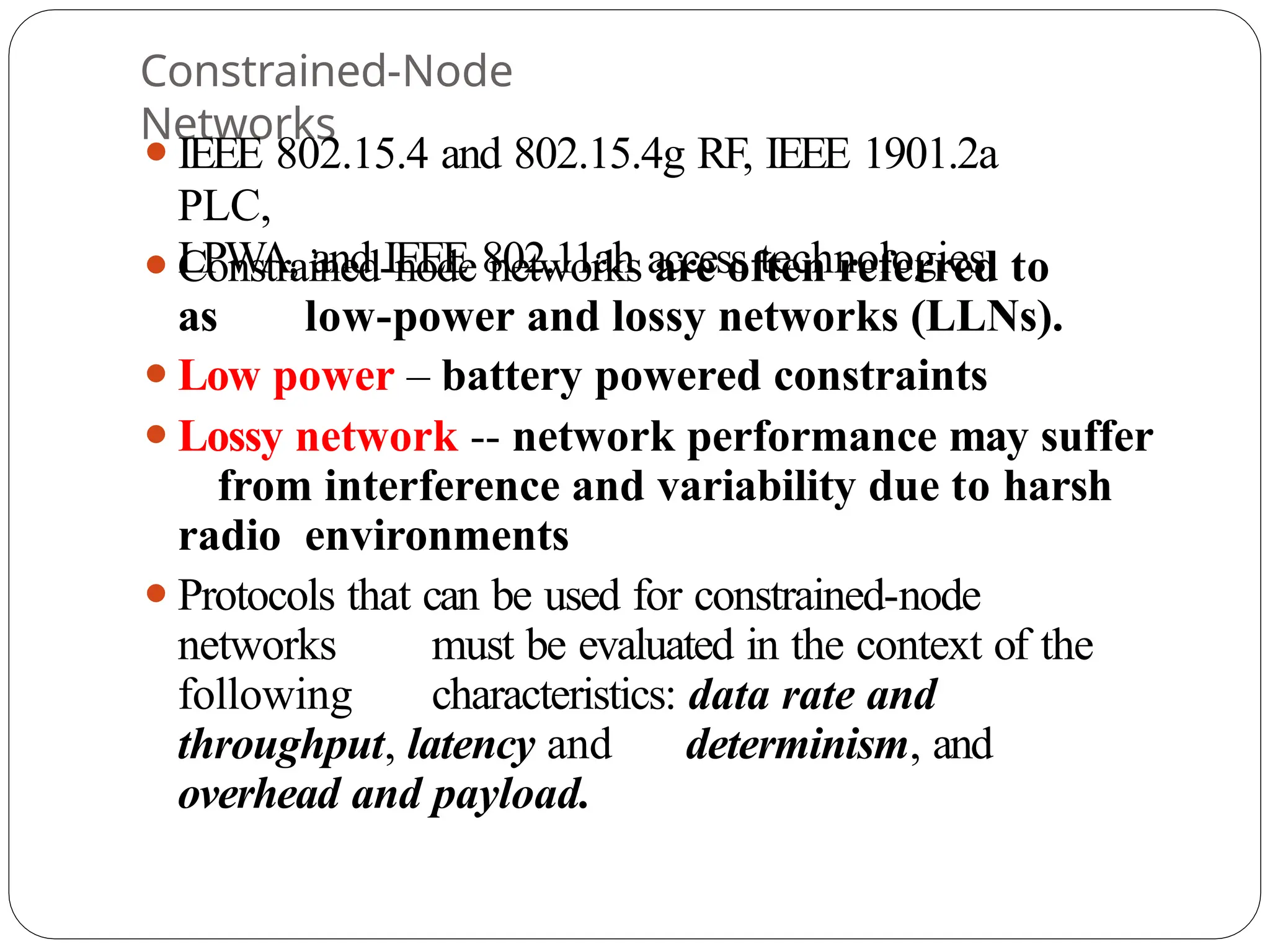
Constrained-Node
Networks
⚫IEEE 802.15.4 and802.15.4g RF, IEEE 1901.2a
PLC,
LPWA, and IEEE 802.11ah access technologies
⚫Constrained-node networks are often referred to
as low-power and lossy networks (LLNs).
⚫Low power – battery powered constraints
⚫Lossy network -- network performance may suffer
from interference and variability due to harsh
radio environments
⚫Protocols that can be used for constrained-node
networks must be evaluated in the context of the
following characteristics: data rate and
throughput, latency and determinism, and
overhead and payload.
64.
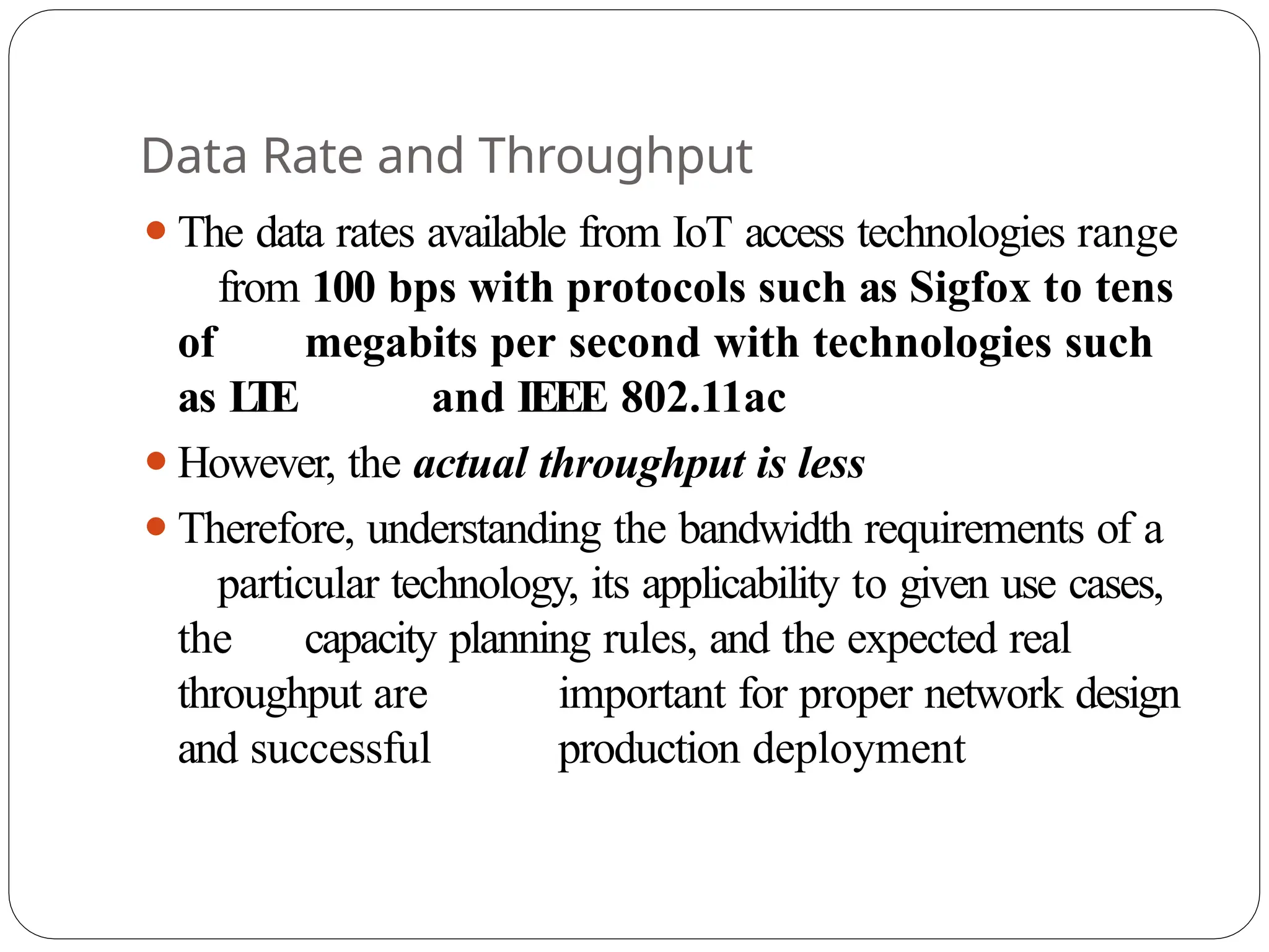
Data Rate andThroughput
⚫The data rates available from IoT access technologies range
from 100 bps with protocols such as Sigfox to tens
of megabits per second with technologies such
as L
TE and IEEE 802.11ac
⚫However, the actual throughput is less
⚫Therefore, understanding the bandwidth requirements of a
particular technology, its applicability to given use cases,
the capacity planning rules, and the expected real
throughput are important for proper network design
and successful production deployment
65.
⚫Technologies not particularlydesigned for IoT, such as
cellular and Wi-Fi, match up well to IoT applications
with high bandwidth requirements
⚫For example, nodes involved with video analytics have a
need for high data rates, IoT endpoints are not
constrained in terms of computing or network bandwidth,
the design guidelines tend to focus on application
requirements, such as latency and determinism
66.
⚫Short-range technologies canalso provide medium to
high data rates that have enough throughput to
connect a few endpoints.
⚫For example, Bluetooth sensors that are now appearing
on connected wearables fall into this category.
⚫In this case, the solutions focus more on footprint and
battery lifetime than on data rate.
⚫The IoT access technologies developed for constrained
nodes are optimized for low power consumption, but they
are also limited in terms of data rate
67.
⚫Another characteristic ofIoT devices is that a majority
of them initiate the communication.
⚫Upstream traffic toward an application server is usually
more common than downstream traffic from the
application server.
⚫Understanding this behavior also helps when deploying
an IoT access technology, such as cellular, that is
asymmetrical because the upstream bandwidth must be
considered a key parameter for profiling the
network capacity
68.
Latency and Determinism
⚫Latencyexpectations of IoT applications should be
known when selecting an access technology
⚫This is particularly true for wireless networks,
where packet loss and retransmissions due to
interference, collisions, and noise are normal
behaviors
⚫On constrained networks, latency may range from
a few milliseconds to seconds, and applications and
protocol stacks must cope with these wide-
ranging values
69.
Overhead and Payload
⚫Whenconsidering constrained access network
technologies, it is important to review the MAC
payload size characteristics required by
applications
⚫Y
ou should be aware of any requirements for IP.
⚫ The minimum IPv6 MTU size is expected to be
1280 bytes.
⚫Therefore, the fragmentation of the IPv6 payload
has to be taken into account by link layer access
protocols with smaller MTUs
70.
IoT Access
Technologies
⚫The followingtopics are addressed for each
IoT access technology:
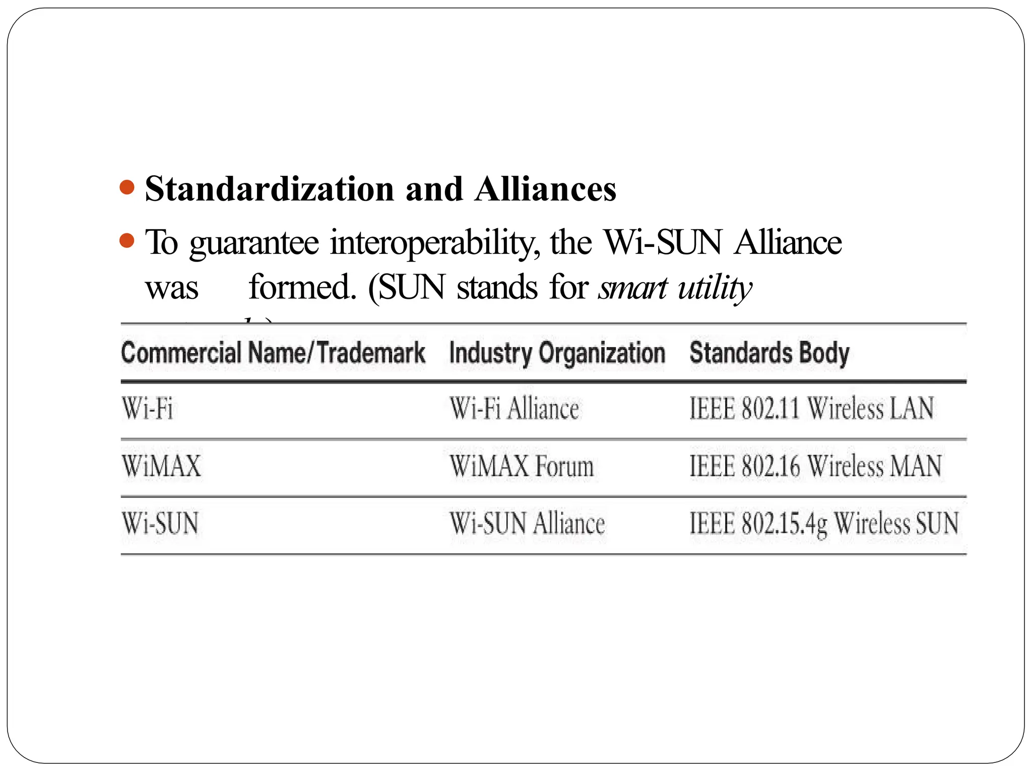
Standardization and alliances:
⚫ The standards bodies that maintain the protocols for a technology
Physical layer:
⚫ The wired or wireless methods and relevant frequencies
MAC layer:
⚫ Considerations at the Media Access Control (MAC) layer, which bridges
the physical layer with data link control
Topology:
⚫ The topologies supported by the technology
Security:
⚫ Security aspects of the technology
Competitive technologies:
⚫ Other technologies that are similar and may be suitable alternatives to the
given technology
71.
⚫IEEE 802.15.4
⚫IEEE 802.15.4gand 802.15.4e
⚫IEEE 1901.2a
⚫IEEE 802.11ah
⚫LoRaWAN
⚫NB-IoT and other LTE
Variations
IoT Access Technologies
72.
IEEE
802.15.4
⚫Wireless access technologyfor low-cost and low-data-
rate devices that are powered or run on batteries
⚫This access technology enables easy installation
while remaining both simple and flexible
⚫IEEE 802.15.4 is commonly found in the following
types of deployments:
⚫Home and building automation
⚫Automotive networks
⚫Industrial wireless sensor networks
⚫Interactive toys and remote controls
73.
⚫Drawbacks of thisincludes MAC reliability, unbounded
latency,
and susceptibility to interference and multipath fading
⚫The negatives around reliability and latency often have to
do with the Collision Sense Multiple Access/Collision
Avoidance (CSMA/CA) algorithm.
⚫CSMA/CA is an access method in which a device “listens”
to make sure no other devices are transmitting before
starting its own transmission.
⚫If another device is transmitting, a wait time (which is
usually
random) occurs before “listening” occurs again
⚫Interference and multipath fading occur with IEEE
802.15.4 because it lacks a frequency-hopping
technique
74.
Standardization and Alliances
⚫IEEE802.15.4 or IEEE 802.15 Task Group 4 defines
low- data-rate PHY and MAC layer specifications
for wireless personal area networks (WPAN).
⚫This is a well-known solution for low complexity
wireless devices with low data rates that need
many months or even years of battery life.
⚫IEEE 802.15.4-2003 , 802.15.4-2006 , 802.15.4-
2011 and
802.15.4-2015
ZigBe
e
⚫ZigBee solutions areaimed at smart objects and
sensors that have low bandwidth and low
power needs.
⚫Furthermore, products that are ZigBee compliant and
certified by the ZigBee Alliance should
interoperate even though different vendors may
manufacture them
⚫The Zigbee specification has undergone several revisions.
⚫In the 2006 revision, sets of commands and message
types were introduced, and increased in number in the
2007 (called Zigbee pro) iteration, to achieve different
functions for a device, such as metering,
temperature, or lighting control
78.
⚫The main areaswhere ZigBee is the most well-known
include automation for commercial, retail, and home
applications and smart energy
⚫In the industrial and commercial automation space,
ZigBee- based devices can handle various functions,
from measuring temperature and humidity to
tracking assets.
⚫For home automation, ZigBee can control lighting, ZigBee
Smart Energy brings together a variety of
interoperable products, such as smart meters,
that can monitor and control the use and delivery
of utilities, such as electricity and water
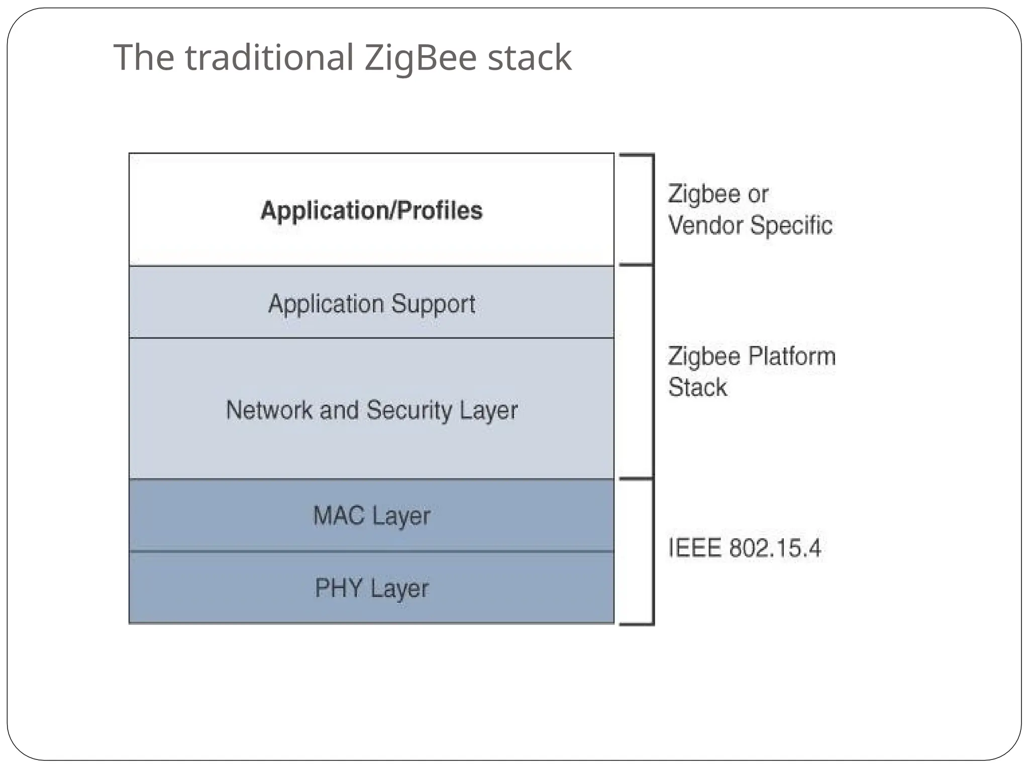
⚫The ZigBee networkand security layer provides
mechanisms for network startup, configuration,
routing, and securing communications.
⚫This includes calculating routing paths in what is often a
changing topology, discovering neighbors, and managing
the routing tables as devices join for the first time.
⚫The network layer is also responsible for forming the
appropriate topology, which is often a mesh but could
be a star or tree as well.
⚫From a security perspective, ZigBee utilizes 802.15.4 for security
at the MAC layer
, using the Advanced Encryption
Standard (AES) with a 128-bit key and also
provides security at the network and
application layers.
81.
⚫ZigBee uses Adhoc On-Demand Distance
Vector (AODV) routing across a mesh
network.
⚫Interestingly, this routing algorithm does not send a
message until a route is needed.
⚫Assuming that the next hop for a route is not in its
routing table, a network node broadcasts a
request for a routing connection.
⚫This causes a burst of routing related traffic, but after a
comparison of various responses, the path with the
lowest number of hops is determined for the
connection.
82.
⚫The application supportlayer interfaces the lower
portion of the stack dealing with the networking of ZigBee
devices with the higher-layer applications.
⚫ZigBee predefines many application profiles for
certain industries, and vendors can optionally create
their own custom ones at this layer.
⚫As mentioned previously, Home Automation and /mart
Energy are two examples of popular application
profiles.
83.
ZigBee
IP
⚫With the introductionof ZigBee IP, the support of IEEE
802.15.4 continues, but the IP and TCP/UDP protocols
and various other open standards are now supported at the
network and transport layers.
⚫The ZigBee-specific layers are now found only at the top
of the protocol stack for the applications
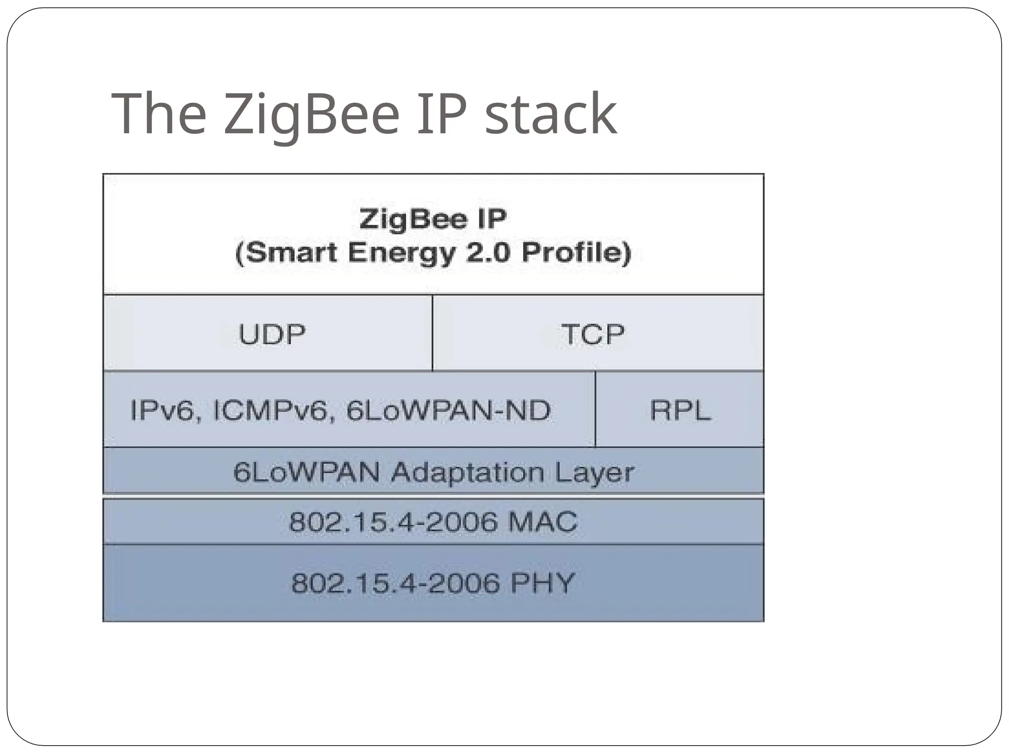
⚫ ZigBee IPsupports 6LoWPAN as an adaptation layer.
⚫ The 6LoWPAN mesh addressing header is not required as
ZigBee IP utilizes the mesh-over or route-over method for
forwarding packets.
⚫ ZigBee IP requires the support of 6LoWPAN’s fragmentation
and
header compression schemes.
⚫ At the network layer, all ZigBee IP nodes support IPv6,
ICMPv6, and 6LoWPAN Neighbor Discovery (ND), and utilize
RPL for the routing of packets across the mesh network.
⚫ Both TCP and UDP are also supported, to provide both
connection-oriented and connectionless service.
86.
Physical
Layer
⚫The 802.15.4 standardsupports an extensive number
of PHY options that range from 2.4 GHz to sub-
GHz frequencies in ISM bands
⚫The original IEEE 802.15.4-2003 standard specified only
three PHY options based on direct sequence spread
spectrum (DSSS) modulation.
⚫DSSS is a modulation technique in which a signal is
intentionally spread in the frequency domain, resulting
in greater bandwidth.
87.
Modulation
⚫In the modulationprocess, some parameter of the
carrier wave (such as amplitude, frequency or
phase ) is varied in accordance with the modulating
signal .This modulated signal is then transmitted
by the transmitter
⚫In the modulation process, two signals are used namely
the modulating signal and the carrier
⚫The modulating signal is nothing but the baseband signal
or information signal while the carrier is a high
frequency sinusoidal signal
88.
⚫Advantages of Modulation
⚫Reductionin the height of antenna
⚫Avoids mixing of signals
⚫Increases the range of
communication
⚫Multiplexing is possible
⚫Improves quality of reception
89.
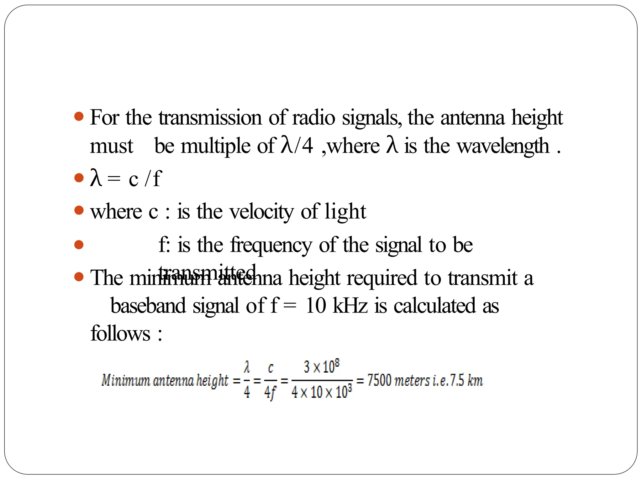
⚫For the transmissionof radio signals, the antenna height
must be multiple of λ/4 ,where λ is the wavelength .
⚫λ = c /f
⚫where c : is the velocity of light
⚫ f: is the frequency of the signal to be
transmitted
⚫The minimum antenna height required to transmit a
baseband signal of f = 10 kHz is calculated as
follows :
90.
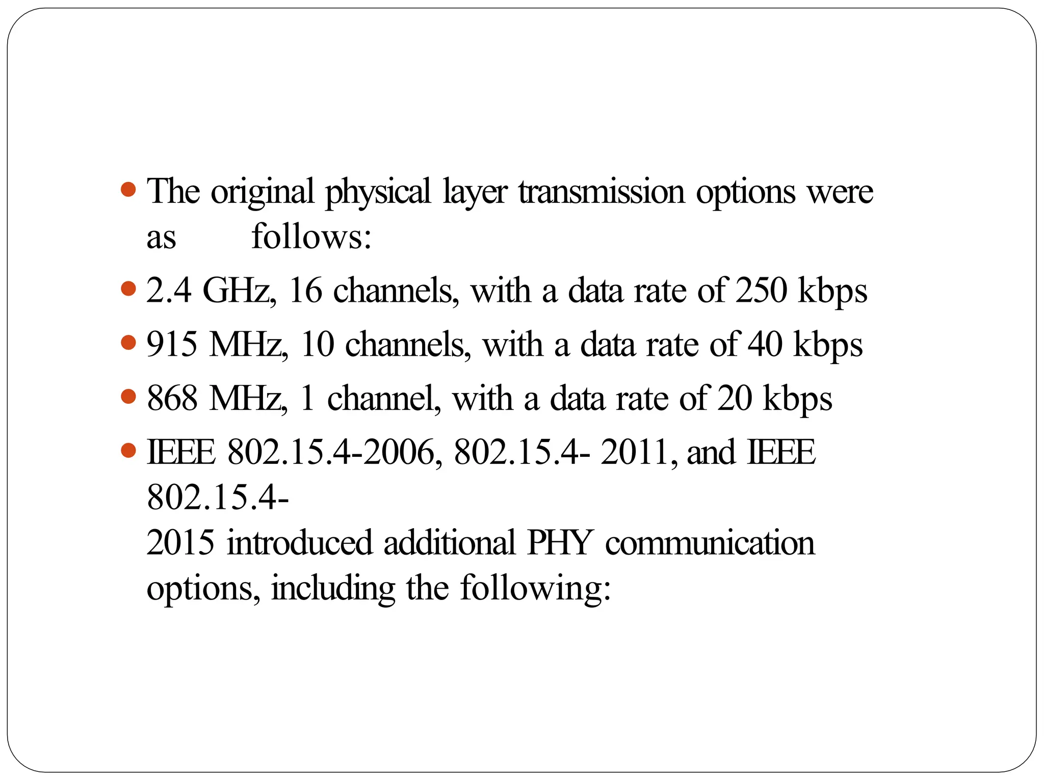
⚫The original physicallayer transmission options were
as follows:
⚫2.4 GHz, 16 channels, with a data rate of 250 kbps
⚫915 MHz, 10 channels, with a data rate of 40 kbps
⚫868 MHz, 1 channel, with a data rate of 20 kbps
⚫IEEE 802.15.4-2006, 802.15.4- 2011, and IEEE
802.15.4-
2015 introduced additional PHY communication
options, including the following:
91.
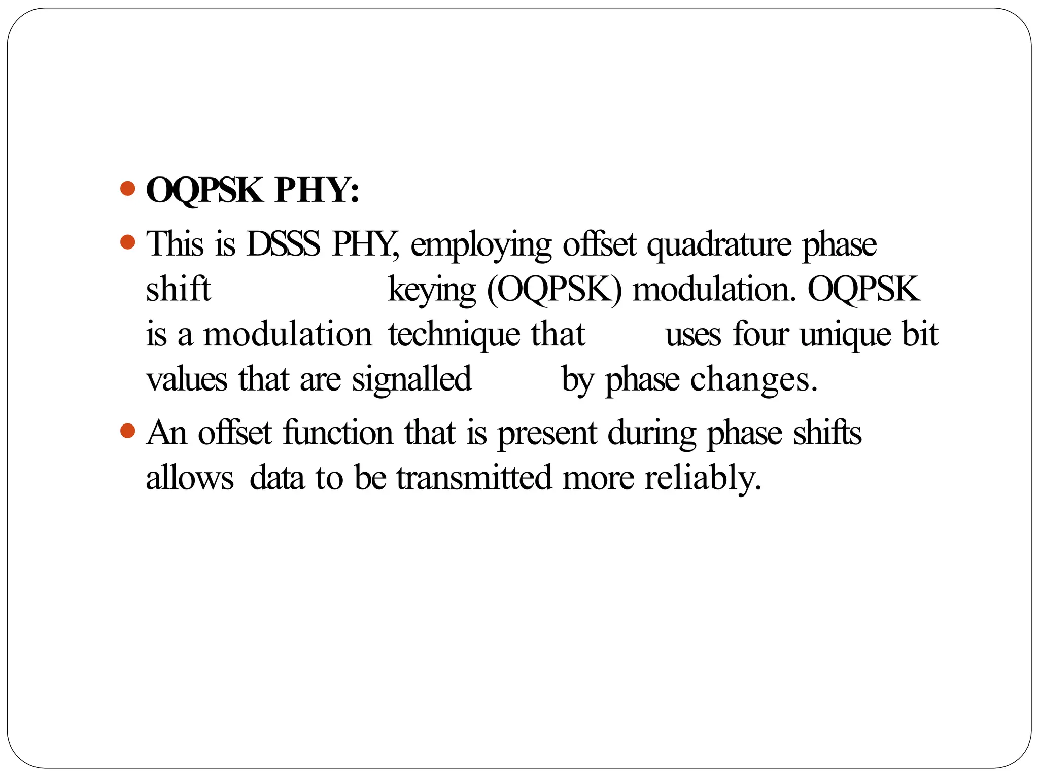
⚫OQPSK PHY:
⚫This isDSSS PHY
, employing offset quadrature phase
shift keying (OQPSK) modulation. OQPSK
is a modulation technique that uses four unique bit
values that are signalled by phase changes.
⚫An offset function that is present during phase shifts
allows data to be transmitted more reliably.
92.
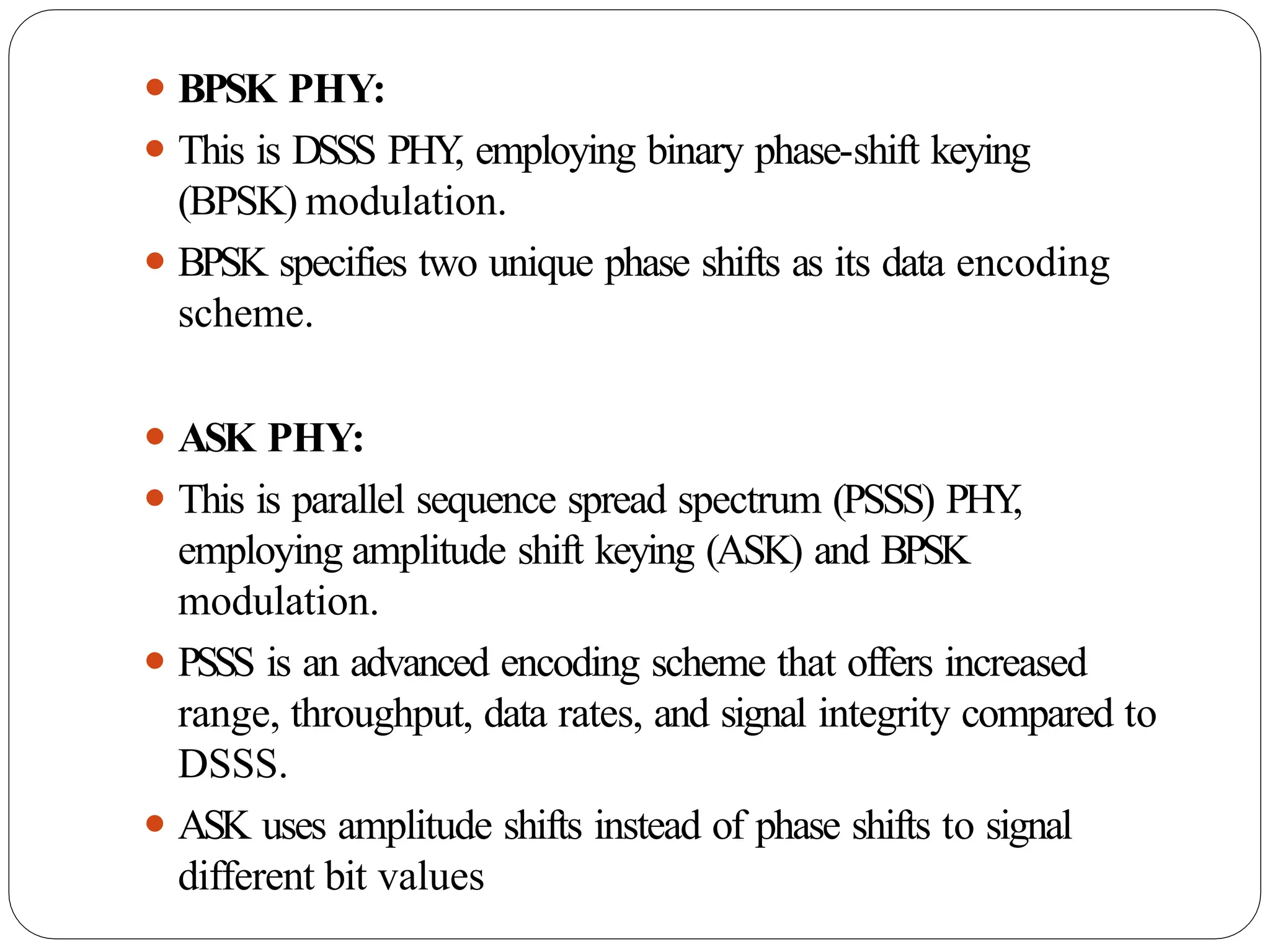
⚫ BPSK PHY:
⚫This is DSSS PHY
, employing binary phase-shift keying
(BPSK) modulation.
⚫ BPSK specifies two unique phase shifts as its data encoding
scheme.
⚫ ASK PHY:
⚫ This is parallel sequence spread spectrum (PSSS) PHY
,
employing amplitude shift keying (ASK) and BPSK
modulation.
⚫ PSSS is an advanced encoding scheme that offers increased
range, throughput, data rates, and signal integrity compared to
DSSS.
⚫ ASK uses amplitude shifts instead of phase shifts to signal
different bit values
93.
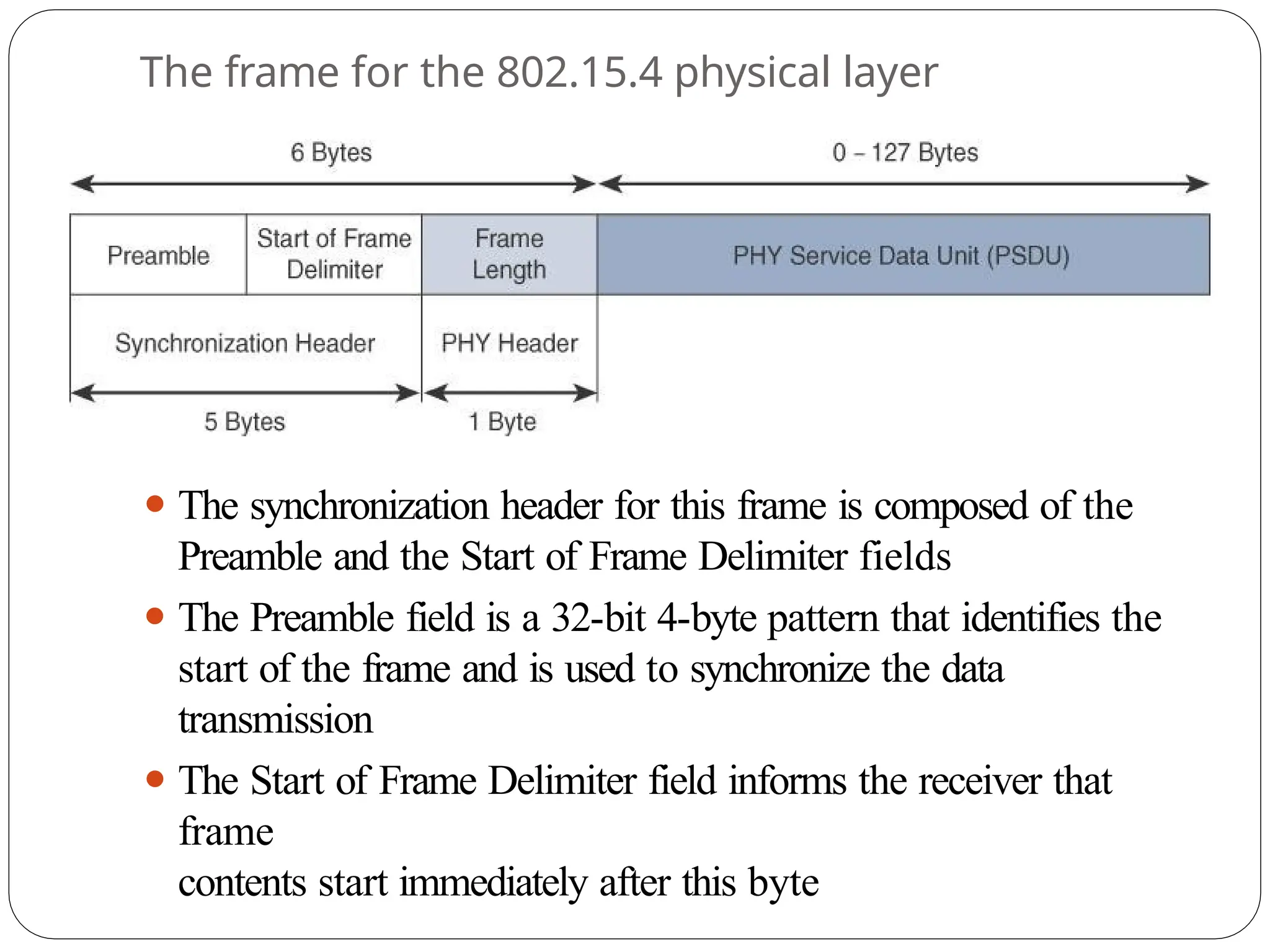
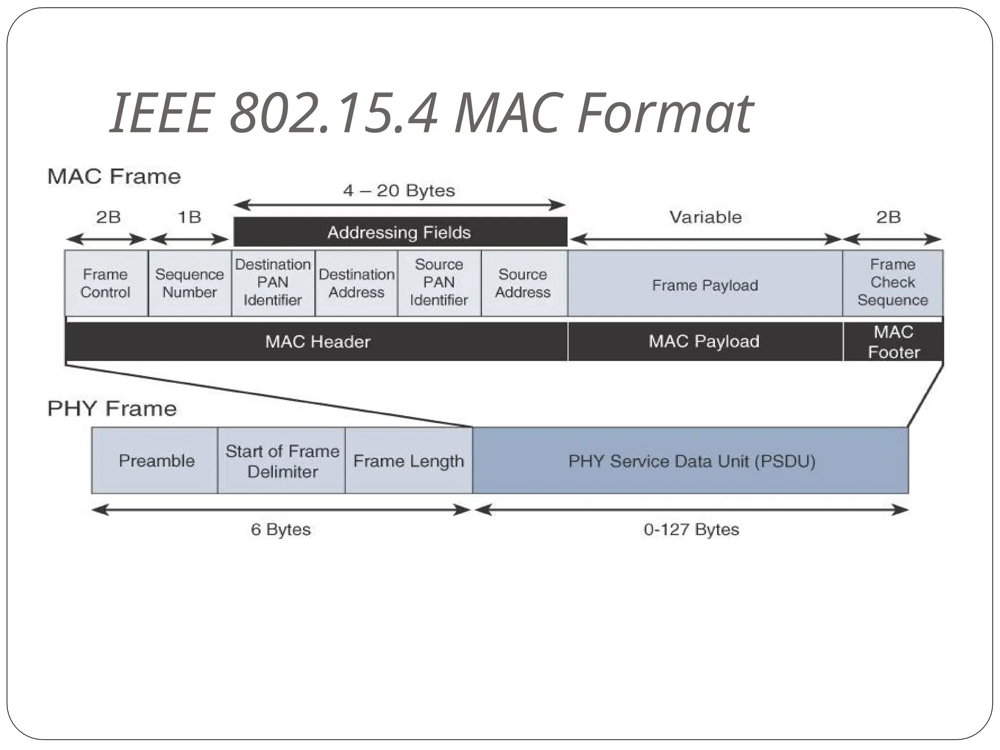
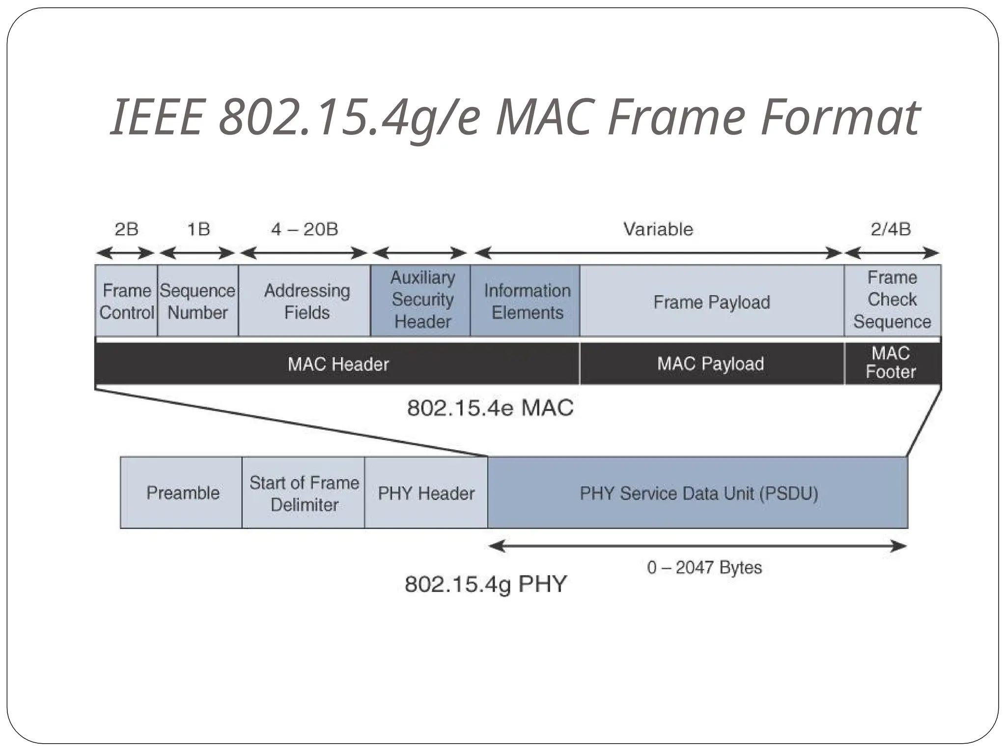
The frame forthe 802.15.4 physical layer
⚫ The synchronization header for this frame is composed of the
Preamble and the Start of Frame Delimiter fields
⚫ The Preamble field is a 32-bit 4-byte pattern that identifies the
start of the frame and is used to synchronize the data
transmission
⚫ The Start of Frame Delimiter field informs the receiver that
frame
contents start immediately after this byte
94.
⚫The PHY Headerportion of the PHY frame is frame
length value. It lets the receiver know how much total
data to expect in the PHY service data unit (PSDU)
portion of the
802.4.15 PHY.
⚫The PSDU is the data field or payload
⚫ The maximum size of the IEEE 802.15.4 PSDU is 127 bytes.This size is
significantly smaller than the lowest MTU setting of other upper-layer
protocols, such as IPv6, which has a minimum MTU setting of 1280
bytes. Therefore, fragmentation of the IPv6 packet must occur at the data
link layer for larger IPv6 packets to be carried over IEEE 802.15.4
frames.
95.
MAC
Layer
⚫At this layer,the scheduling and routing of data frames
are coordinated
⚫The 802.15.4 MAC layer performs the following tasks:
⚫Network beaconing for devices acting as coordinators
(New devices use beacons to join an 802.15.4 network)
⚫PAN association and disassociation by a device
⚫Device security
⚫Reliable link communications between two peer
MAC entities
96.
⚫ The MAClayer achieves these tasks by using various
predefined frame types
⚫ Four types of MAC frames are specified in 802.15.4:
⚫ Data frame:
⚫ Handles all transfers of data
⚫ Beacon frame:
⚫ Used in the transmission of beacons from a P
AN coordinator
⚫ Acknowledgement frame:
⚫ Confirms the successful reception of a frame
⚫ MAC command frame:
⚫ Responsible for control communication between devices
⚫The MAC Headerfield is composed of the Frame
Control, Sequence Number and the Addressing
fields.
⚫The Frame Control field defines attributes such as
frame type, addressing modes, and other control
flags.
⚫The Sequence Number field indicates the sequence
identifier for the frame.
⚫The Addressing field specifies the Source and
Destination PAN Identifier fields as well as the
Source and Destination Address fields
99.
⚫The MAC Payloadfield varies by individual frame type.
⚫For example, beacon frames have specific fields and
payloads related to beacons, while MAC command
frames have different fields present.
⚫The MAC Footer field is nothing more than a frame
check sequence (FCS).
⚫An FCS is a calculation based on the data in the frame that
is used by the receiving side to confirm the integrity
of the data in the frame.
100.
⚫IEEE 802.15.4 requiresall devices to support a unique 64-
bit extended MAC address, based on EUI-64.
⚫However, because the maximum payload is 127 bytes,
802.15.4 also defines how a 16-bit “short address” is
assigned
to devices.
⚫This short address is local to the PAN and substantially
reduces the frame overhead compared to a 64-bit
extended MAC address
101.
Topology
⚫IEEE 802.15.4–based networkscan be built as star, peer-
to- peer, or mesh topologies.
⚫Mesh networks tie together many nodes.
⚫This allows nodes that would be out of range if trying
to communicate directly to leverage intermediary
nodes to transfer communications.
⚫Every 802.15.4 PAN should be set up with a unique
ID.
⚫All the nodes in the same 802.15.4 network should use
the same P
AN ID
103.
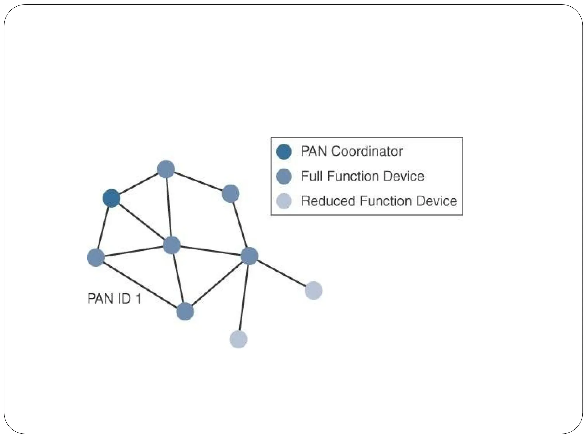
⚫A minimum ofone FFD acting as a PAN coordinator
is required to deliver services that allow other
devices to associate and form a cell or PAN.
⚫A single PAN coordinator is identified for PAN ID 1.
⚫FFD devices can communicate with any other
devices, whereas RFD devices can
communicate only with FFD devices.
104.
⚫The IEEE 802.15.4specification does not define a
path selection within the MAC layer for a mesh
topology.
⚫This function can be done at Layer 2 and is known as
mesh- under.
⚫The routing function can occur at Layer 3, using a
routing protocol, such as the IPv6 Routing
Protocol for Low Power and Lossy Networks
(RPL).
⚫This is referred to as mesh-over
105.
Security
⚫ The IEEE802.15.4 specification uses Advanced Encryption
Standard (AES) with a 128-bit key length as the base
encryption algorithm for securing its data
⚫ AES is a block cipher, which means it operates on fixed-size
blocks of data
⚫ symmetric key - means that the same key is used for both
the encryption and decryption of the data
⚫ In addition to encrypting the data, AES in 802.15.4 also
validates the data that is sent.
⚫ This is accomplished by a message integrity code (MIC), which
is calculated for the entire frame using the same AES key that is
used for encryption
106.
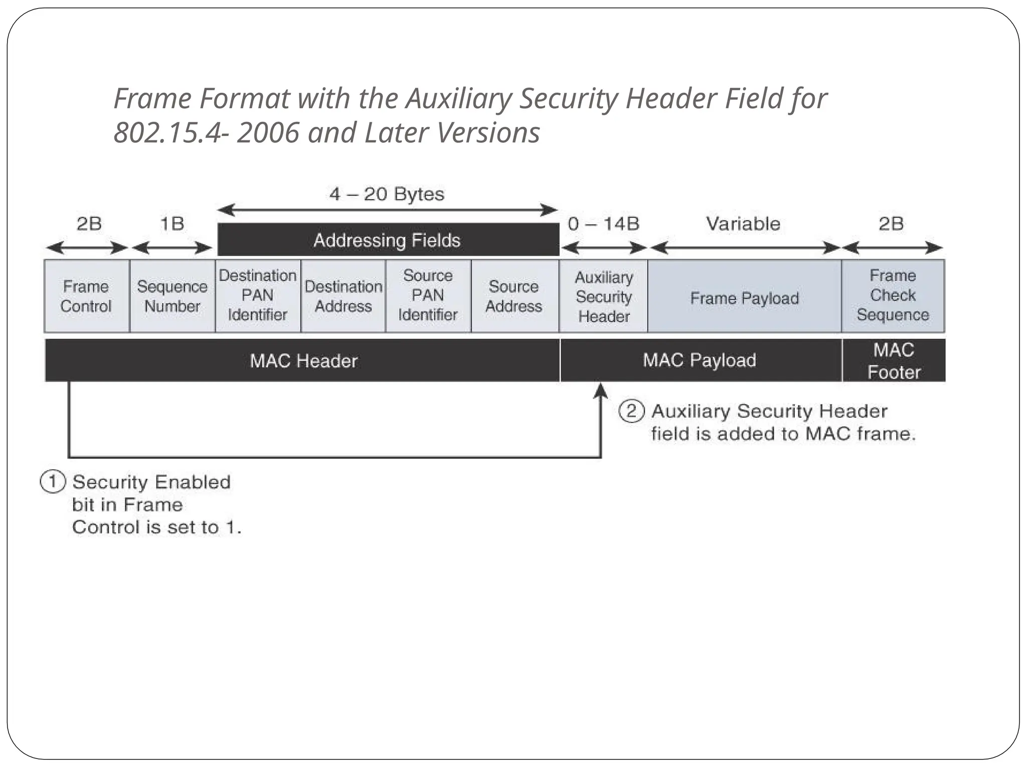
⚫Using the SecurityEnabled field in the Frame Control
portion of the 802.15.4 header is the first step to
enabling AES encryption.
⚫This field is a single bit that is set to 1 for security.
⚫Once this bit is set, a field called the Auxiliary Security
Header is created after the Source Address field, by
stealing some bytes from the Payload field.
107.
Frame Format withthe Auxiliary Security Header Field for
802.15.4- 2006 and Later Versions
108.
IEEE 802.15.4g and802.15.4e
⚫The IEEE 802.15.4e amendment of 802.15.4-2011
expands the MAC layer feature set to remedy the
disadvantages associated with 802.15.4, including MAC
reliability, unbounded latency, and multipath fading
⚫Also made improvements to better cope with certain
application domains, such as factory and process
automation and smart grid
⚫IEEE 802.15.4e-2012 enhanced the IEEE 802.15.4 MAC
layer capabilities in the areas of frame format,
security, determinism mechanism, and frequency
hopping
109.
⚫IEEE 802.15.4g-2012 isalso an amendment to the
IEEE 802.15.4-2011 standard
⚫The focus of this specification is the smart grid or,
more specifically, smart utility network
communication.
⚫802.15.4g seeks to optimize large outdoor wireless
mesh networks for field area networks (FANs)
110.
⚫This technology appliesto IoT use cases such as
the following:
⚫ Distribution automation and industrial supervisory
control and data acquisition (SCADA) environments for
remote monitoring and control
⚫ Public lighting
⚫ Environmental wireless sensors in smart cities
⚫ Electrical vehicle charging stations
⚫ Smart parking meters
⚫ Microgrids
⚫ Renewable energy
Physical
Layer
⚫PSDU or payloadsize of 127 bytes was increased for
the SUN PHY to 2047 bytes
⚫This provides a better match for the greater packet
sizes found in many upper-layer protocols.
⚫For example, the default IPv6 MTU setting is 1280
bytes.
⚫Fragmentation is no longer necessary at Layer 2 when
IPv6 packets are transmitted over IEEE 802.15.4g
MAC frames.
⚫The error protection was improved in IEEE 802.15.4g
by evolving the CRC from 16 to 32 bits
113.
⚫The SUN PHY
,as described in IEEE 802.15.4g-2012,
supports multiple data rates in bands ranging from 169
MHz to 2.4 GHz.
⚫These bands are covered in the unlicensed ISM
frequency spectrum
⚫Within these bands, data must be modulated onto
the frequency using at least one of the following
PHY mechanisms to be IEEE 802.15.4g
compliant:
⚫Multi-Rate and Multi-Regional Frequency
Shift Keying (MR-FSK)
⚫Offers good transmit power efficiency due to the
constant envelope of the transmit signal
114.
⚫Multi-Rate and Multi-RegionalOrthogonal
Frequency Division Multiplexing (MR-
OFDM)
⚫Provides higher data rates but may be too complex for
low- cost and low-power devices
⚫Multi-Rate and Multi-Regional Offset
Quadrature Phase-Shift Keying (MR-O-QPSK)
⚫Shares the same characteristics of the IEEE 802.15.4-
2006 O-QPSK PHY
, making multi-mode systems more
cost- effective and easier to design
⚫Enhanced data rates and a greater number of channels
for channel hopping are available, depending on the
frequency bands and modulation
115.
MAC Layer
⚫Time-Slotted ChannelHopping (TSCH):
⚫It is an IEEE 802.15.4e-2012 MAC operation mode
that works to guarantee media access and channel
diversity.
⚫Channel hopping, also known as frequency hopping,
utilizes different channels for transmission at
different times.
⚫TSCH divides time into fixed time periods, or “time
slots,”
which offer guaranteed bandwidth and predictable
latency.
⚫In a time slot, one packet and its acknowledgement can be
transmitted, increasing network capacity because
multiple nodes can communicate in the same time
116.
⚫A number oftime slots are defined as a “slot frame,”
which is regularly repeated to provide “guaranteed
access.”
⚫The transmitter and receiver agree on the channels and
the timing for switching between channels through
the combination of a global time slot counter and a
global channel hopping sequence list
117.
⚫Information elements:
⚫Information elements(IEs) allow for the exchange of
information at the MAC layer in an extensible manner,
either as header IEs (standardized) and/or payload IEs
(private).
⚫Specified in a tag, length, value (TLV) format, the IE
field allows frames to carry additional metadata to
support MAC layer services
⚫These services may include IEEE 802.15.9 key
management, Wi-SUN 1.0 IEs to broadcast and unicast
schedule timing information, and frequency hopping
synchronization information for the 6TiSCH
architecture.
118.
⚫Enhanced beacons (EBs):
⚫EBsextend the flexibility of IEEE 802.15.4 beacons to
allow the construction of application-specific beacon
content.
⚫This is accomplished by including relevant IEs in EB
frames.
⚫Some IEs that may be found in EBs include network
metrics, frequency hopping broadcast schedule, and
P
AN information version.
119.
⚫Enhanced beacon requests(EBRs):
⚫Like enhanced beacons, an enhanced beacon request
(EBRs) also leverages IEs.
⚫The IEs in EBRs allow the sender to selectively specify
the request of information.
⚫Beacon responses are then limited to what was requested
in the EBR.
⚫For example, a device can query for a PAN that is
allowing new devices to join or a PAN that
supports a certain set of MAC/PHY capabilities
120.
⚫Enhanced Acknowledgement:
⚫The EnhancedAcknowledgement frame allows for
the integration of a frame counter for the frame
being acknowledged.
⚫This feature helps protect against certain attacks that
occur when Acknowledgement frames are spoofed.
⚫The main changesshown in the IEEE 802.15.4e header
are the presence of the Auxiliary Security Header and
Information Elements field.
⚫The Auxiliary Security header provides for the encryption
of the data frame
⚫The IE field contains one or more information elements
that allow for additional information to be exchanged at
the MAC layer.
123.
Topology
⚫Deployments of IEEE802.15.4g-2012 are mostly based on
a mesh topology
⚫Mesh topology is typically the best choice for use cases in
the industrial and smart cities areas
⚫A mesh topology allows deployments to be done in urban
or rural areas, expanding the distance between nodes
that can relay the traffic of other nodes.
124.
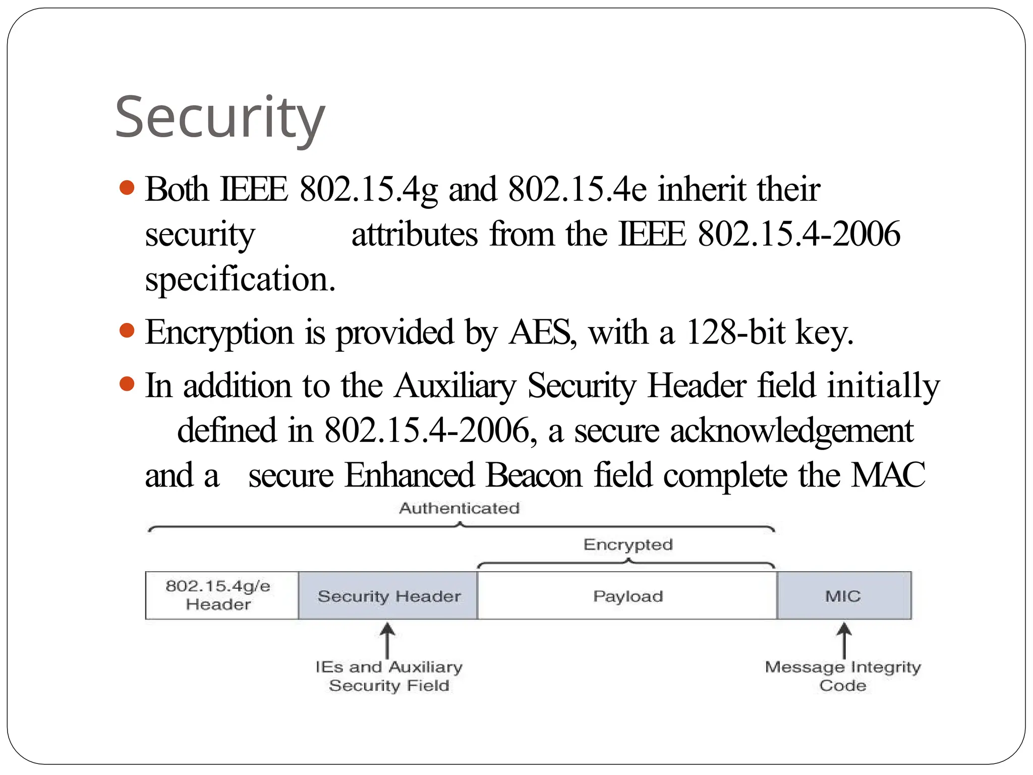
Security
⚫Both IEEE 802.15.4gand 802.15.4e inherit their
security attributes from the IEEE 802.15.4-2006
specification.
⚫Encryption is provided by AES, with a 128-bit key.
⚫In addition to the Auxiliary Security Header field initially
defined in 802.15.4-2006, a secure acknowledgement
and a secure Enhanced Beacon field complete the MAC
layer security
125.
⚫ The fullframe gets authenticated through the MIC at the end
of frame.
⚫ The MIC is a unique value that is calculated based on the
frame contents.
⚫ The Security Header field denoted is composed of the
Auxiliary Security field and one or more Information
Elements fields.
⚫ Integration of the Information Elements fields allows for
the adoption of additional security capabilities, such as the
IEEE
802.15.9 Key Management Protocol (KMP) specification.
⚫ KMP provides a means for establishing keys for robust
datagram
security
126.
IEEE 1901.2a
⚫IEEE 1901.2a-2013is a wired technology that is an update
to the original IEEE 1901.2 specification.
⚫This is a standard for Narrowband Power
Line Communication (NB-PLC).
⚫NB-PLC leverages a narrowband spectrum for low
power, long range, and resistance to interference
over the same wires that carry electric power.
127.
⚫NB-PLC is oftenfound in use cases such as the
following:
⚫Smart metering:
⚫NB-PLC can be used to automate the reading of
utility meters, such as electric, gas, and water
meters
⚫Distribution automation:
⚫NB-PLC can be used for distribution automation,
which involves monitoring and controlling all the
devices in the power grid.
128.
⚫ Public lighting:
⚫A common use for NB-PLC is with public lighting—the lights
found in cities and along streets, highways, and public areas such
as parks.
⚫ Electric vehicle charging stations:
⚫ NB-PLC can be used for electric vehicle charging stations,
where the batteries of electric vehicles can be recharged.
⚫ Microgrids:
⚫ NB-PLC can be used for microgrids, local energy grids that
can disconnect from the traditional grid and operate
independently.
⚫ Renewable energy:
⚫ NB-PLC can be used in renewable energy applications, such
as solar, wind power, hydroelectric, and geothermal heat.
129.
LoRaWAN
⚫Low-Power Wide-Area (LPWA)adapted for long-range
and battery powered endpoints
⚫LoRaWAN is unlicensed-band LPW
A technology
⚫LoRa was a physical layer, or Layer 1, modulation that
was developed by a French company named Cycleo
⚫Later, Cycleo was acquired by Semtech
⚫Optimized for long-range, two-way communications and
low power consumption
Physical
Layer
⚫Semtech LoRa modulationis based on chirp spread
spectrum modulation
⚫Chirp - Compressed High Intensity Radar Pulse
⚫Lower data rate and increase the communication distance
132.
⚫Understanding LoRa gatewaysis critical to understanding
a LoRaWAN system.
⚫A LoRa gateway is deployed as the center hub of a
star network architecture.
⚫It uses multiple transceivers and channels and can
demodulate multiple channels at once or even
demodulate multiple signals on the same channel
simultaneously.
⚫LoRa gateways serve as a transparent bridge relaying
data between endpoints, and the endpoints use a
single-hop wireless connection to communicate
with one or many gateways.
133.
⚫ The datarate in LoRaW
AN varies depending on the
frequency bands and adaptive data rate (ADR).
⚫ ADR is an algorithm that manages the data rate and radio
signal for each endpoint.
⚫ The ADR algorithm ensures that packets are delivered at the
best data rate possible and that network performance is both
optimal and scalable.
⚫ Endpoints close to the gateways with good signal values
transmit with the highest data rate, which enables a shorter
transmission time over the wireless network, and the lowest
transmit power.
⚫ Meanwhile, endpoints at the edge of the link budget
communicate
at the lowest data rate and highest transmit power.
134.
⚫An important featureof LoRa is its ability to handle
various data rates via the spreading factor.
⚫Devices with a low spreading factor (SF) achieve less
distance in their communications but transmit at
faster speeds, resulting in less airtime.
⚫A higher SF provides slower transmission rates but achieves
a higher reliability at longer distances.
135.
MAC
Layer
⚫The MAC layeris defined in the LoRaW
AN
specification.
⚫This layer takes advantage of the LoRa physical layer and
classifies LoRaWAN endpoints to optimize their battery
life and ensure downstream communications to the
LoRaWAN endpoints.
⚫The LoRaW
AN specification documents three classes
of LoRaWAN devices:
⚫Class A:
⚫This class is the default implementation. Optimized
for battery powered nodes, it allows
bidirectional communications, where a given node
is able to receive downstream traffic after
transmitting.
⚫Two receive windows are available after each
136.
⚫Class B:
⚫This classwas designated“experimental” in LoRaW
AN
1.0.1 until it can be better defined.
⚫A Class B node or endpoint should get additional
receive windows compared to Class A, but
gateways must be synchronized through a
beaconing process
⚫Class C:
⚫This class is particularly adapted for powered nodes.
⚫This classification enables a node to be continuously
listening by keeping its receive window open when
not transmitting.
137.
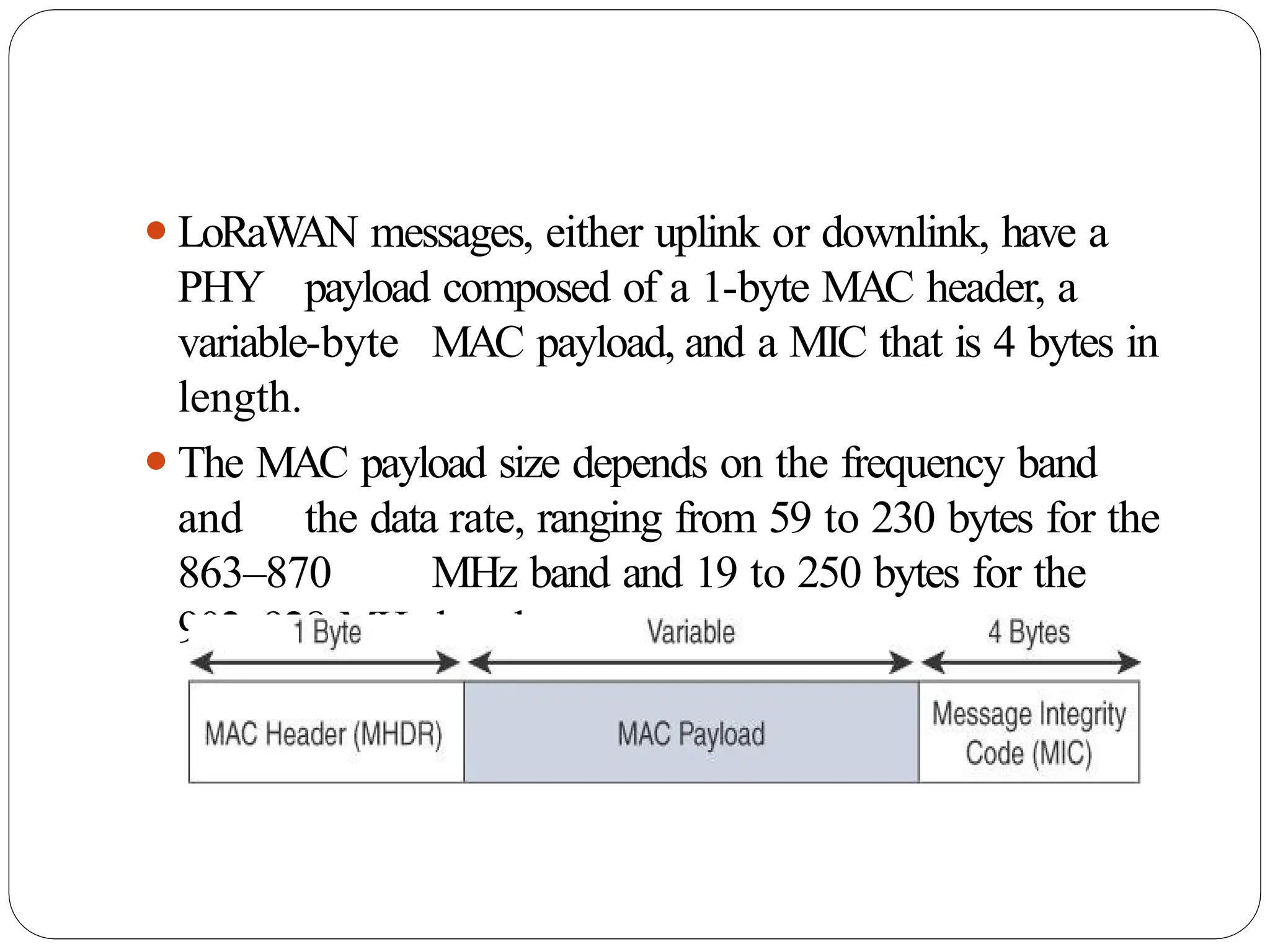
⚫LoRaW
AN messages, eitheruplink or downlink, have a
PHY payload composed of a 1-byte MAC header, a
variable-byte MAC payload, and a MIC that is 4 bytes in
length.
⚫The MAC payload size depends on the frequency band
and the data rate, ranging from 59 to 230 bytes for the
863–870 MHz band and 19 to 250 bytes for the
902–928 MHz band
138.
⚫ In version1.0.x, LoRaW
AN utilizes six MAC message types.
⚫ LoRaW
AN devices use join request and join accept messages
for activation and joining the network.
⚫ The other message types are unconfirmed data up/down and
confirmed data up/down.
⚫ A “confirmed” message is one that must be acknowledged,
and “unconfirmed” signifies that the end device does not
need to acknowledge.
⚫ “up/down” is simply a directional notation identifying
whether the
message flows in the uplink or downlink path.
⚫ Uplink messages are sent from endpoints to the network
server and are relayed by one or more LoRaW
AN gateways.
⚫ Downlink messages flow from the network server to a
single endpoint and are relayed by only a single gateway
139.
⚫LoRaWAN endpoints areuniquely addressable through
a variety of methods, including the following:
⚫An endpoint can have a global end device ID or
DevEUI represented as an IEEE EUI-64
address.
⚫An endpoint can have a global application ID or AppEUI
represented as an IEEE EUI-64 address that uniquely
identifies the application provider, such as the owner, of
the end device
140.
⚫In a LoRaWANnetwork, endpoints are also known by
their end device address, known as a DevAddr, a 32-bit
address.
⚫The 7 most significant bits are the network
identifier (NwkID), which identifies the
LoRaW
AN network.
⚫The 25 least significant bits are used as the network
address (NwkAddr) to identify the endpoint in the
network.
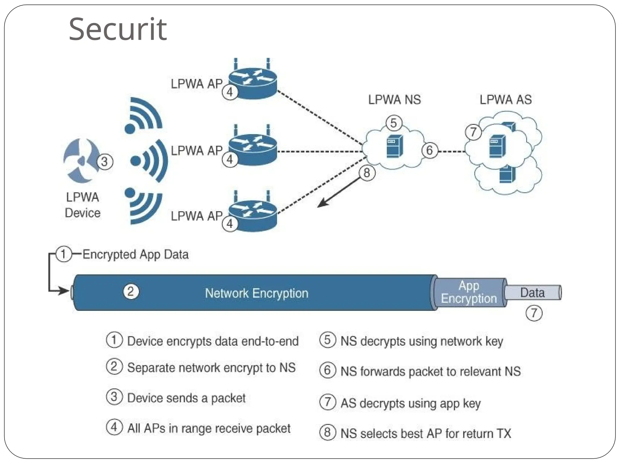
⚫LoRaWAN endpoints mustimplement two layers of
security, protecting communications and data privacy
across the network.
⚫The first layer, called “network security” but applied at the
MAC layer, guarantees the authentication of the
endpoints by the LoRaW
AN network server.
⚫Also, it protects LoRaW
AN packets by
performing encryption based on AES
143.
⚫Each endpoint implementsa network session key
(NwkSKey), used by both itself and the LoRaW
AN
network server.
⚫The NwkSKey ensures data integrity through computing
and checking the MIC of every data message as well as
encrypting and decrypting MAC-only data message
payloads
⚫The second layer is an application session key
(AppSKey), which performs encryption and
decryption functions between the endpoint and its
application server
144.
⚫LoRaWAN endpoints attachedto a LoRaWAN network
must get registered and authenticated.
⚫This can be achieved through one of the two
join mechanisms:
⚫Activation by personalization (ABP):
⚫Endpoints don’t need to run a join procedure as their
individual details, including DevAddr and the NwkSKey
and AppSKey session keys, are preconfigured and
stored in the end device.
⚫This same information is registered in the
LoRaWAN network server
145.
⚫ Over-the-air activation(OTAA):
⚫ Endpoints are allowed to dynamically join a particular
LoRaWAN
network after successfully going through a join procedure.
⚫ The join procedure must be done every time a session context
is renewed.
⚫ During the join process, which involves the sending and
receiving of MAC layer join request and join accept messages,
the node establishes its credentials with a LoRaW
AN network
server, exchanging its globally unique DevEUI, AppEUI, and
AppKey.
⚫ The AppKey is then used to derive the session NwkSKey and
AppSKey keys
146.
NB-IoT and OtherLTE
Variations
⚫Existing cellular technologies, such as GPRS, Edge, 3G,
and 4G/LTE, are not particularly well adapted to
battery- powered devices and small objects
specifically developed for the Internet of Things
⚫L
TE -M
⚫The new LTE-M device category was not sufficiently close
to LPW
A capabilities
⚫A new narrowband radio access technology
called Narrowband IoT (NB-IoT)
147.
⚫It addresses therequirements of a massive number of
low- throughput devices, low device power
consumption, improved indoor coverage, and
optimized network architecture
148.
LTE Cat 0
⚫Thefirst enhancements to better support IoT devices
in 3GPP occurred in L
TE Release 12.
⚫A new user equipment (UE) category, Category 0, was
added, with devices running at a maximum data rate
of 1 Mbps
⚫Category 0 includes important characteristics to
be supported by both the network and end
devices
149.
⚫ Power savingmode (PSM)
⚫ This new device status minimizes energy consumption
⚫ PSM is defined as being similar to “powered off ” mode, but
the
device stays registered with the network.
⚫ By staying registered, the device avoids having to reattach or
re- establish its network connection
⚫ The device negotiates with the network the idle time after
which it will wake up.
⚫ When it wakes up, it initiates a tracking area update (TAU),
after which it stays available for a configured time and then
switches back to sleep mode or PSM.
⚫ A T
AU is a procedure that an L
TE device uses to let the
network know its current tracking area, or the group of
towers in the network from which it can be reached
150.
⚫Half-duplex mode
⚫This modereduces the cost and complexity of a
device’s
implementation because a duplex filter is not needed.
⚫Most IoT endpoints are sensors that send low amounts
of data that do not have a full duplex
communication requirement.
151.
⚫L
TE-M
⚫L
TE Release 13
⚫Lowerreceiver bandwidth
⚫Bandwidth has been lowered to 1.4 MHz versus the usual
20 MHz.This further simplifies the LTE endpoint
⚫Lower data rate
⚫Data is around 200 kbps for LTE-M, compared to 1 Mbps
for Cat 0.
152.
⚫Half-duplex mode
⚫Just aswith Cat 0, LTE-M offers a half-duplex mode
that decreases node complexity and cost
⚫Enhanced discontinuous reception (eDRX)
⚫This capability increases from seconds to minutes the
amount
of time an endpoint can “sleep” between paging cycles