Copyright 2005, AvayaInc.
All Rights Reserved
This document contains information related to
Avaya Communication Manager (as defined
below) and Documentation (“Product”).
“Documentation” means this document and
Avaya’s information manuals in printed or
electronic form containing operating instructions
and performance specifications that Avaya or its
suppliers generally make available to users of its
products, and which Avaya delivers to End User
with the Products. “End User” means any
customer of Avaya or its authorized resellers, or
any end user of the Product. See the Software
and Documentation DVD/CD inserts for additional
legal and licensing information.
This document includes:
Notice
Disclaimer
Warranty
License
Copyright
Security and virus disclaimer
Trademarks
Notice
Changes and corrections to the information in this
document may be incorporated in future releases.
Disclaimer
Avaya, its affiliates or subsidiaries (“Avaya”) are
not responsible for any modifications, additions or
deletions to the original published version of the
Documentation unless such modifications,
additions or deletions were performed by Avaya.
End User agrees to indemnify and hold harmless
Avaya, Avaya's agents, servants, directors,
officers, and employees against all claims,
lawsuits, demands and judgments arising out of,
or in connection with, subsequent modifications,
additions or deletions to the Documentation to the
extent made by the End User.
Warranty
Avaya provides a limited warranty on the Product.
Refer to your customer sales agreement to
establish the terms of the limited warranty. In
addition, Avaya’s standard warranty language as
well as information regarding support for the
Product, while under warranty, is available
through the following web site:
http://www.avaya.com/support.
License
USE OR INSTALLATION OF THE PRODUCT
INDICATES THE END USER’S ACCEPTANCE
OF THE GENERAL LICENSE TERMS
AVAILABLE ON THE AVAYA WEBSITE AT:
http://www.avaya.com/support (“GENERAL
LICENSE TERMS”). DO NOT USE THE
PRODUCT IF YOU DO NOT WISH TO BE
BOUND BY THE GENERAL LICENSE TERMS.
IN ADDITION TO THE GENERAL LICENSE
TERMS, THE FOLLOWING LICENSE TERMS
AND RESTRICTIONS WILL APPLY TO THE
PRODUCT.
Avaya grants End User a license within the scope
of the license types described below. The
applicable number of licenses and units of
capacity for which the license is granted will be
one (1), unless a different number of licenses or
units of capacity is specified in the Documentation
or other materials available to End User.
“Designated Processor” means a single
stand-alone computing device. “Server” means a
Designated Processor that hosts a software
application to be accessed by multiple users.
“Software” means the computer programs in
object code, originally licensed by Avaya and
ultimately utilized by End User, whether as
stand-alone products or pre-installed on
Hardware. “Hardware” means the standard
hardware products, originally sold by Avaya and
ultimately utilized by End User.
Designated System(s) License (DS). End User
may install and use each copy of the Software on
only one Designated Processor, unless a different
number of Designated Processors is indicated in
the Documentation or other materials available to
End User. Avaya may require the Designated
Processor(s) to be identified by type, serial
number, feature key, location or other specific
designation, or to be provided by End User to
Avaya through electronic means established by
Avaya specifically for this purpose.
Concurrent User License (CU). End User may
install and use the Software on multiple
Designated Processors or one or more Servers,
so long as only the licensed number of Units are
accessing and using the Software at any given
time. A “Unit” means the unit on which Avaya, at
its sole discretion, bases the pricing of its licenses
and can be, without limitation, an agent, port or
user, an e-mail or voice mail account in the name
of a person or corporate function (e.g., webmaster
or helpdesk), or a directory entry in the
administrative database utilized by the Product
that permits one user to interface with the
Software. Units may be linked to a specific,
identified Server.
3.
Named User License(NU). Customer may: (i)
install and use the Software on a single
Designated Processor or Server per authorized
Named User (defined below); or (ii) install and use
the Software on a Server so long as only
authorized Named Users access and use the
Software. “Named User,” means a user or device
that has been expressly authorized by Avaya to
access and use the Software. At Avaya’s sole
discretion, a “Named User” may be, without
limitation, designated by name, corporate function
(e.g., webmaster or helpdesk), an e-mail or voice
mail account in the name of a person or corporate
function, or a directory entry in the administrative
database utilized by the Product that permits one
user to interface with the Product.
Shrinkwrap License (SR). With respect to
Software that contains elements provided by third
party suppliers, End User may install and use the
Software in accordance with the terms and
conditions of the “shrinkwrap” or “clickwrap”
license accompanying the Software (“Shrinkwrap
License”). The text of the Shrinkwrap License will
be available from Avaya upon End User’s request
(see “Copyright” below for more information).
Copyright
Except where expressly stated otherwise, the
Product is protected by copyright and other laws
respecting proprietary rights. Unauthorized
reproduction, transfer, and or use can be a
criminal, as well as a civil, offense under the
applicable law.
Certain Software programs or portions thereof
included in the Product may contain software
distributed under third party agreements (“Third
Party Components”), which may contain terms
that expand or limit rights to use certain portions of
the Product (“Third Party Terms”). Information
identifying Third Party Components and the Third
Party Terms that apply to them is available on
Avaya’s web site at
http://www.avaya.com/support.
The disclaimers of warranties and limitations of
liability set forth in the Third Party Terms do not
affect any express warranty or limitation of liability
that may be provided to you by Avaya pursuant to
the license terms covering the Product contained
in a separate written agreement between you and
Avaya. To the extent there is a conflict between
the General License Terms or your customer
sales agreement and any Third Party Terms, the
Third Party Terms shall prevail solely for such
Third Party Components.
Security and virus disclaimer
End User's decision to acquire products from third
parties is End User's sole responsibility, even if
Avaya helps End User identify, evaluate or select
them. Avaya is not responsible for, and will not be
liable for, the quality or performance of such third
party products or their suppliers.
ALL INFORMATION IS BELIEVED TO BE
CORRECT AT THE TIME OF PUBLICATION AND
IS PROVIDED "AS IS". AVAYA DISCLAIMS ALL
WARRANTIES, EITHER EXPRESS OR IMPLIED,
INCLUDING THE WARRANTIES OF
MERCHANTABILITY AND FITNESS FOR A
PARTICULAR PURPOSE AND FURTHERMORE,
AVAYA MAKES NO REPRESENTATIONS OR
WARRANTIES THAT THE STEPS
RECOMMENDED WILL ELIMINATE SECURITY
OR VIRUS THREATS TO END USER’
SYSTEMS. IN NO EVENT SHALL AVAYA BE
LIABLE FOR ANY DAMAGES WHATSOEVER
ARISING OUT OF OR IN CONNECTION WITH
THE INFORMATION OR RECOMMENDED
ACTIONS PROVIDED HEREIN, INCLUDING
DIRECT, INDIRECT, CONSEQUENTIAL
DAMAGES, LOSS OF BUSINESS PROFITS OR
SPECIAL DAMAGES, EVEN IF AVAYA HAS
BEEN ADVISED OF THE POSSIBILITY OF
SUCH DAMAGES.
Avaya does not warrant that this Product is
immune from or will prevent unauthorized use of
telecommunication services or facilities accessed
through or connected to it. Avaya is not
responsible for any damages or charges that
result from either unauthorized uses or from
incorrect installations of the security patches that
are made available from time to time.
Suspected security vulnerabilities with Avaya
products should be reported to Avaya by sending
mail to securityalerts@avaya.com.
Trademarks
All trademarks identified by ®
and TM
are
registered trademarks or trademarks of Avaya Inc.
All other trademarks are the property of their
respective owners.
5.
Issue 2 June2005 5
Welcome. . . . . . . . . . . . . . . . . . . . . . . . 9
Why this book? . . . . . . . . . . . . . . . . . . . . . . . 9
We wrote this book for you!. . . . . . . . . . . . . . . . . 9
Information contained in this book. . . . . . . . . . . . . 10
How to use this book . . . . . . . . . . . . . . . . . . . . 11
Admonishments . . . . . . . . . . . . . . . . . . . . . . . 12
Systems, circuit packs, and media modules. . . . . . 14
Trademarks. . . . . . . . . . . . . . . . . . . . . . . . . . 15
Security concerns . . . . . . . . . . . . . . . . . . . . . . 15
Related books . . . . . . . . . . . . . . . . . . . . . . . . 15
Tell us what you think! . . . . . . . . . . . . . . . . . . . 16
How to get this book on the Web . . . . . . . . . . . . . . 16
How to order more copies . . . . . . . . . . . . . . . . . 17
How to get help . . . . . . . . . . . . . . . . . . . . . . . 18
1: Keeping system information . . . . . . . . . . . 19
Keeping baseline information . . . . . . . . . . . . . . . 19
Retrieving baseline information . . . . . . . . . . . . . . 20
Securing backups . . . . . . . . . . . . . . . . . . . . . . 23
2: Checking system status . . . . . . . . . . . . . . 25
Problem solving strategies . . . . . . . . . . . . . . . . . 25
Viewing the system status . . . . . . . . . . . . . . . 26
Viewing general system operations . . . . . . . . . . 27
Viewing the status of a station . . . . . . . . . . . . . 27
Viewing the status of your cabinets . . . . . . . . . . 28
Viewing changes to the system . . . . . . . . . . . . 29
Contents
Why this book?
Issue2 June 2005 9
Welcome
Why this book?
You’ve told us that you want more information on how to keep your
system up and running. This book contains the basic technical
knowledge you need to understand your telephone system running
Avaya Communication Manager.
There are some differences between the different versions of the
software, but the information provided will help you with the most
basic operations.
We wrote this book for you!
Use this book if you are a system administrator. Use it before you
attend training, and take it with you to your class. Mark it up, make
notes in it, and use it daily even after you complete training.
This book is for you if:
● You are a new administrator taking over from someone else.
● You are filling in for your company’s regular administrator.
● You want to refresh your memory.
10.
Welcome
10 Basic DiagnosticsQuick Reference
Information contained in this book
The Basic Diagnostics Quick Reference is divided into sections to
guide you through your day-to-day operations.
Keeping system information explains what kind of baseline
information you should keep and how to retrieve the information from
your system. It also shows you how to verify that your backups are
successful.
Checking system status explains different problem-solving strategies.
It also tells you how to view the status of your system and any
changes that have been made.
Solving common problems tells you what questions to ask to solve
common problems. It walks you through examples of diagnosing and
correcting typical problems, and explains how to solve basic call
center problems.
Alarms and errors provides information on maintenance reports,
frequently- encountered error types, and how to prevent some alarms
and errors.
Using features to troubleshoot explains how to use specific features
to determine the status of telephones, trunk lines, and facilities.
Solving IP and H.323 problems tells you how to solve basic IP
Softphone and IP trunk and H.323 trunk problems.
Contacting Avaya explains how to escalate problems to Avaya and
lists what information you should gather before you call.
11.
How to usethis book
Issue 2 June 2005 11
How to use this book
Become familiar with the following terms and conventions. They help
you use this book with Communication Manager.
● A “screen” is the display of fields and prompts that appear on a
terminal monitor. See Figure 1: Help screen for status
command on page 26 for an example of a screen and how it is
shown in this book.
● Avaya uses the term “telephone” in this book. Other books
might refer to telephones as voice terminals, stations, or
endpoints.
● Keys and buttons are printed in a bold font: Key.
● Titles of screens are printed in a bold font: Screen Name.
● Names of fields are printed in a bold font: Field Name.
● Text (other than commands) that you need to type into a field
are printed in a bold font: text.
● Commands are printed in a bold constant width font: command.
● Variables are printed in a bold constant width italic font:
variable.
● We show complete commands in this book, but you can use an
abbreviated version of the command. For example, instead of
typing list configuration station, you can type list
config sta.
● If you need help constructing a command or completing a field,
remember to use Help.
- When you press Help at any point on the command line, the
system displays a list of available commands.
- When you press Help with your cursor in a field on a screen,
the system displays a list of valid entries for that field.
12.
Welcome
12 Basic DiagnosticsQuick Reference
● Messages that the system displays are printed in a bold font:
system message.
● To move to a certain field on a screen, you can use the Tab key,
directional arrows, or the Enter key on your keyboard.
● If you use terminal emulation software, you need to determine
what keys correspond to Enter, Return, Cancel, Help, and
Next Page keys.
● We show commands and screens from the newest release of
Communication Manager. Substitute the appropriate
commands for your system and see the manuals you have
available.
● The status line or message line can be found near the bottom of
your monitor. This is where the system displays messages for
you. Check the message line to see how the system responds
to your input. Write down the message if you need to call the
helpline.
● When a procedure requires you to press Enter to save your
changes, the screen clears. The cursor returns to the command
prompt. The message line shows “command successfully
completed” to indicate that the system accepted your changes.
Admonishments
Admonishments that might appear in this book have the following
meanings:
Note:
Note: A note calls attention to neutral information or positive
information that supplements the main text. A note also calls
attention to valuable information that is independent of the
main text.
13.
Admonishments
Issue 2 June2005 13
! Important:
Important: An important note calls attention to situations that can
cause serious inconvenience.
Tip:
Tip: A tip calls attention to information that helps you
apply the techniques and the procedures that the text
describes. A tip can include keyboard shortcuts, or
alternative methods that might not be obvious.
! CAUTION:
CAUTION: A caution statement calls attention to situations that
can result in harm to software, loss of data, or an
interruption of service.
! WARNING:
WARNING: A warning statement calls attention to situations that
can result in harm to hardware or equipment.
! DANGER:
DANGER: A danger statement calls attention to situations that
can result in physical injury to yourself or to other
people.
! SECURITY ALERT:
SECURITY ALERT: A security alert calls attention to situations that can
increase the potential for toll fraud or other
unauthorized use of your telecommunications
system.
ELECTROSTATIC ALERT:
ELECTROSTATIC ALERT: An electrostatic alert calls attention to situations that
can result in damage to electronic components from
electrostatic discharge (ESD).
14.
Welcome
14 Basic DiagnosticsQuick Reference
Systems, circuit packs, and media modules
● The word “system” is a general term encompassing all
references to an Avaya media server running Communication
Manager.
● Circuit pack codes (for example, TN780 or TN2182B) are
shown with the minimum acceptable alphabetic suffix (like the
“B” in the code TN2182B). Generally, an alphabetic suffix higher
than that shown is also acceptable. However, not every vintage
of either the minimum suffix or a higher suffix code is
necessarily acceptable. A suffix of “P” means that firmware can
be downloaded to that circuit pack.
● The term “cabinet” refers to the external casing (shell) of an
MCC1, SCC1, CMC1, G600, or G650 Media Gateway. Circuit
packs are installed in the cabinet in a specific carrier (row), and
in a specific slot within that carrier.
● The designation “UUCSSpp” refers to the location (address) of
a circuit pack in cabinet-carrier-slot-port order. In this address
designation, UU is the cabinet number, C is the carrier letter, SS
is the slot number of a specific circuit pack, and pp (if
applicable) is a specific port on the circuit pack. A sample
address for port 4 on a circuit pack on an MCC1 Media
Gateway might look like this: 02A0704.
● A G350 or G700 Media Gateway uses media modules instead
of circuit packs. The media module address is designated as
XXXVSpp, where XXX is the administered number of the media
gateway, VS is the slot number of a specific media module
location on the media gateway, and pp (if applicable) is a
specific port on the media module. The V is not a variable and
needs to be included in the command exactly where shown. A
sample address for port 4 in slot V3 on an MM711 Media
Module on a G700 Media Gateway might look like this:
002V304. If an S8300 Media Server is installed in a G700
Media Gateway, it must be installed in slot number V1.
15.
Trademarks
Issue 2 June2005 15
Trademarks
All trademarks identified by ®
or ™ are registered trademarks or
trademarks, respectively, of Avaya, Inc. All other trademarks are the
property of their respective owners.
Security concerns
Toll fraud is the theft of long distance service. When toll fraud occurs,
your company is responsible for charges. For information on how to
prevent toll fraud, see the Avaya Toll Fraud and Security Handbook,
555-025-600. You can also call the Avaya Security Hotline at
1 800 643 2353, or contact your Avaya representative.
Related books
There are two companions to this book:
● The Avaya Communication Manager Basic Administration
Quick Reference, 03-300363
● The Avaya Communication Manager Advanced Administration
Quick Reference, 03-300364
The Administrator Guide for Avaya Communication Manager,
03-300509, explains system features and interactions in greater
detail. The Administrator Guide provides a reference how to plan,
operate, and administer your system.
Note:
Note: Prior to April 1997, this same information was in two
separate books: the DEFINITY Implementation and the
DEFINITY Feature Description books.
16.
Welcome
16 Basic DiagnosticsQuick Reference
We also refer to the Overview for Avaya Communication Manager,
03-300468, Administration for Network Connectivity for Avaya
Communication Manager, 555-233-504, and the Avaya Products
Security Handbook, 555-025-600.
Tell us what you think!
Tell us what you like or do not like about this book. Although we
cannot respond personally to all your feedback, we read each
response. Your suggestions make this book more useful for
everyone.
How to get this book on the Web
If you have internet access, you can view and download the latest
version of Avaya Communication Manager Basic Diagnostics Quick
Reference. To view this book, you must have a copy of Acrobat
Reader.
Note:
Note: If you do not have Acrobat Reader, you can get a free copy
at http://www.adobe.com.
Write to us at: Avaya
Product Documentation Group
Room B3-H13
1300 W. 120th Avenue
Denver, CO 80234 USA
Fax to: 1 303 538 1741
Send e-mail to: document@avaya.com
17.
How to ordermore copies
Issue 2 June 2005 17
To get the latest version of this book:
1. Go to the Avaya customer support Web site at
http://www.avaya.com/support/.
2. Click the Search text box.
3. Type 03-300365 (the document number) in the Search text box,
then click the arrow button.
How to order more copies
We can put your name on an order list so you will automatically
receive updated versions of this book. For more information and to
receive future issues of this book, contact the Avaya Publications
Center.
Call: Avaya Publications Center
Voice: 1-800-457-1235 or 1-207-866-6701
Fax: 1-800-457-1764 or 1-207-626-7269
Write: Globalware Solutions
Attn: Avaya Account Management
200 Ward Hill Ave
Haverhill, MA 01835 USA
E-mail: totalware@gwsmail.com
Order: Document No. 03-300365, Issue 2, June 2005
18.
Welcome
18 Basic DiagnosticsQuick Reference
How to get help
If you need additional help, go to the Avaya customer support Web
site at http://www.avaya.com/support/.
● Within the United States, click the Escalation Contacts link
that is located under the Contact Support heading. Then click
the appropriate link for the type of support you need.
● Outside the United States, click the Escalation Contacts link
that is located under the Contact Support heading. Then click
International Services, which includes telephone numbers for
the international Centers of Excellence.
You can also access the following services in the USA. You might
need to purchase an extended service agreement to use some of
these services. Contact your Avaya representative for more
information.
Avaya Communication Manager Helpline
(for help with feature administration and
system applications)
1 800 225 7585
Avaya National Customer Care Center
Support Line (for help with maintenance
and repair)
1 800 242 2121
Avaya Toll Fraud Intervention 1 800 643 2353
Avaya Corporate Security 1 800 822 9009
19.
Keeping baseline information
Issue2 June 2005 19
information
1: Keeping system
information
This section explains what kind of system records to keep and how to
collect the data. It also tells you how to make sure your backups are
successful.
Keeping baseline information
Baseline information consists of:
● the original system configuration
● any upgrades and changes
● switch capabilities (for example, if your company uses a call
center or telecommuting)
The very best set of records starts with information on the original set
up of your system. Most companies keep at least one paper copy of
baseline information, with duplicate paper or electronic copies kept off
site. Update this information any time you make changes to your
system.
Use baseline information to help you diagnose problems with your
telephone system. Also, this information is crucial in the event you
need to reconstruct the information on your system, such as in a
disaster recovery.
20.
Keeping system information
20Basic Diagnostics Quick Reference
Note:
Note: Avaya Warranty and Service Agreement customers are
automatically enrolled in the Emergency Service Plan. The
plan provides coverage for disasters such as fire, flood, and
storms. Under this plan, Avaya restores basic telephone
service on a priority basis. We can also lease a system
running Communication Manager to Warranty and Service
Agreement customers or can ship a replacement system, if
necessary.
Retrieving baseline information
You can retrieve much of the hardware and configuration information
you need right from your System Administration Terminal (SAT).
● Use display commands to see individual records.
● Use list commands to view a group of records.
If you are using a SAT with a local printer attached, you can also:
● Add print to display or list commands to create paper copies
of the records from your system.
● Add schedule to a display or list command to create
paper copies of the records at the system printer (if
administered).
Note:
Note: Be sure your printer is set up to print from the SAT. For more
information, see the Avaya Communication Manager Basic
Administration Quick Reference, 03-300363.
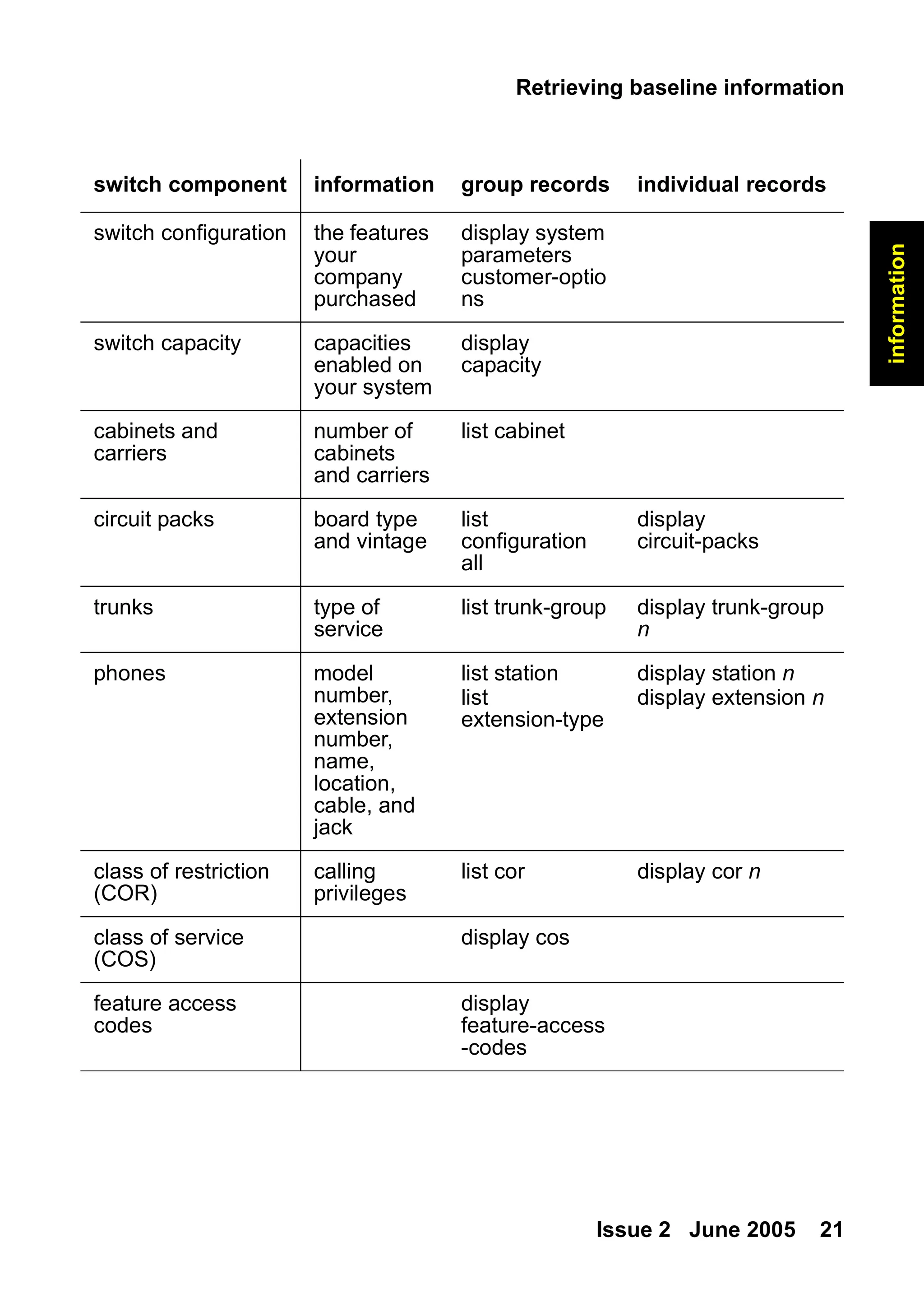
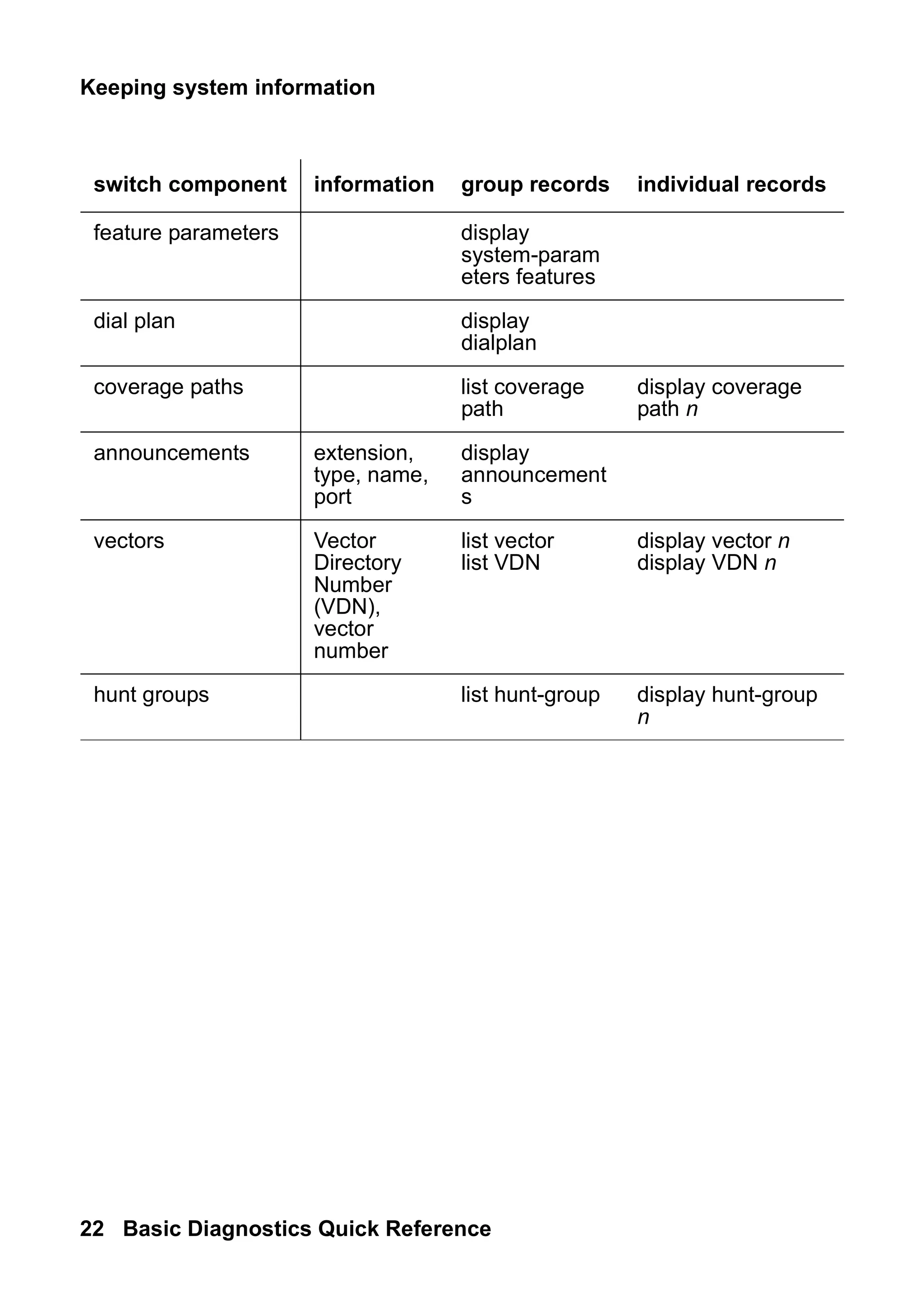
Keep track of the equipment and settings listed in the following table.
Use the commands in the table to access the appropriate screens.
21.
Retrieving baseline information
Issue2 June 2005 21
information
switch component information group records individual records
switch configuration the features
your
company
purchased
display system
parameters
customer-optio
ns
switch capacity capacities
enabled on
your system
display
capacity
cabinets and
carriers
number of
cabinets
and carriers
list cabinet
circuit packs board type
and vintage
list
configuration
all
display
circuit-packs
trunks type of
service
list trunk-group display trunk-group
n
phones model
number,
extension
number,
name,
location,
cable, and
jack
list station
list
extension-type
display station n
display extension n
class of restriction
(COR)
calling
privileges
list cor display cor n
class of service
(COS)
display cos
feature access
codes
display
feature-access
-codes
22.
Keeping system information
22Basic Diagnostics Quick Reference
feature parameters display
system-param
eters features
dial plan display
dialplan
coverage paths list coverage
path
display coverage
path n
announcements extension,
type, name,
port
display
announcement
s
vectors Vector
Directory
Number
(VDN),
vector
number
list vector
list VDN
display vector n
display VDN n
hunt groups list hunt-group display hunt-group
n
switch component information group records individual records
23.
Securing backups
Issue 2June 2005 23
information
Securing backups
Backup your system regularly to keep your records up to date.
● Use save translations to backup changes to your system.
● Use save announcements to backup changes to
announcements.
To verify that a backup was successful, review the Command
Completion Status field.
● If the status field says Success, then the backup of the
translations or the announcements was successful.
● If the status field does not say Success, record the Error Code
and use the following list to determine what happened:
- 1 = unable to save to active-spe device
- 2 = unable to save to standby-spe device
Note:
Note: For more information on performing backups, see the Avaya
Communication Manager Basic Administration Quick
Reference, 03-300363.
Problem solving strategies
Issue2 June 2005 25
status
2: Checking system
status
This section explains how to use system information to keep track of
the general health and status of your system. It tells you how to
access system-wide and individual information, and describes how to
check when changes are made to your system.
Problem solving strategies
As an administrator, one of your responsibilities is to check the status
of your system to determine whether it is performing properly. This is
a proactive approach to system diagnostics.
● Use the status command to check on the operation of your
system. See Viewing the system status on page 26 for more
information.
● Use display alarms and display errors to closely
monitor your system. See Alarms and errors on page 43 for
more information.
Another of your responsibilities is to respond to reports of telephone
problems from your users. You generally have to use a reactive
approach to system diagnostics to perform this important function.
See Solving common problems on page 31 for more information.
26.
Checking system status
26Basic Diagnostics Quick Reference
Viewing the system status
Use system status screens to monitor various parts of your system.
To be prepared for problems, you’ll want to become familiar with what
these reports look like when your system is operating well.
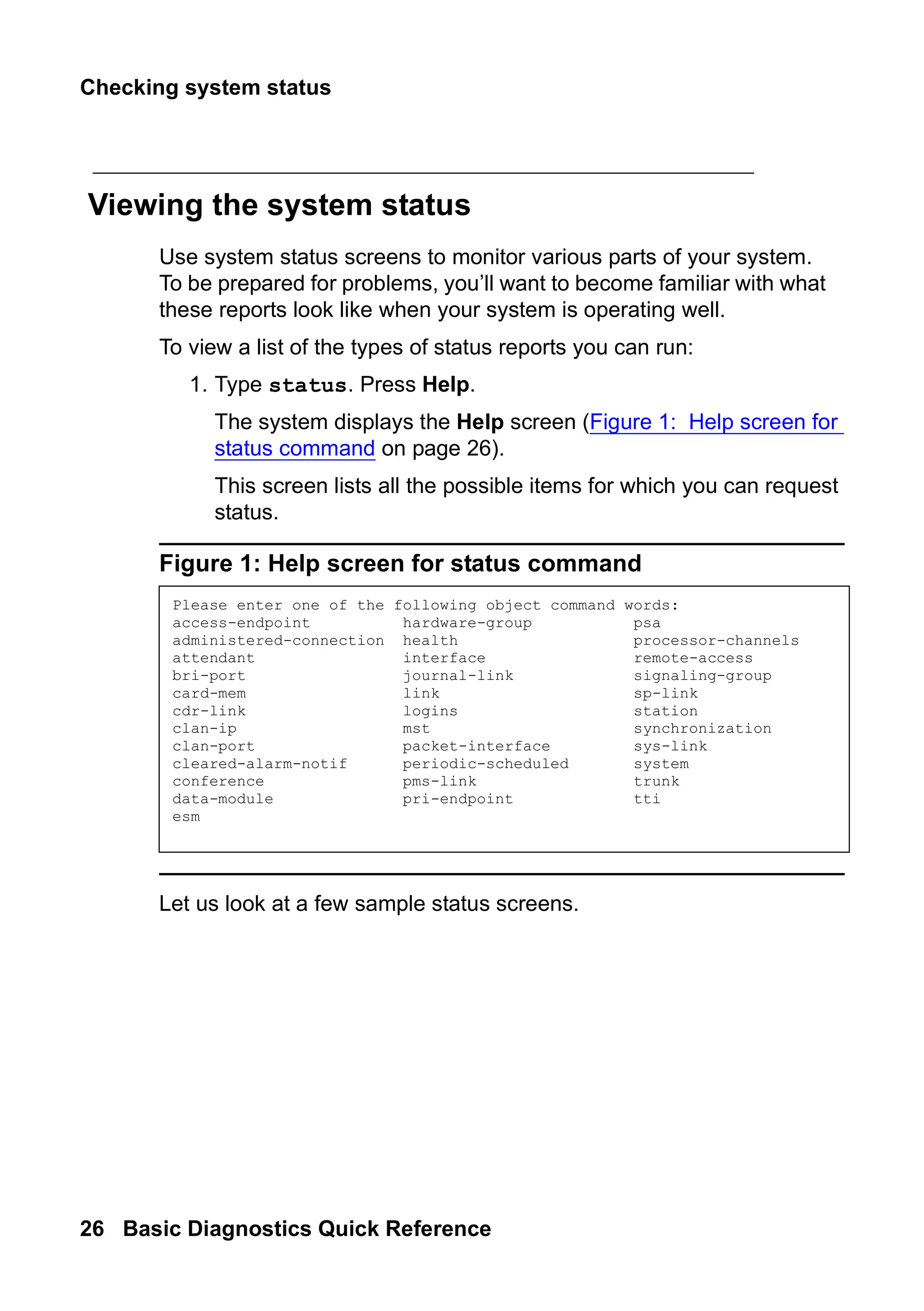
To view a list of the types of status reports you can run:
1. Type status. Press Help.
The system displays the Help screen (Figure 1: Help screen for
status command on page 26).
This screen lists all the possible items for which you can request
status.
Figure 1: Help screen for status command
Let us look at a few sample status screens.
Please enter one of the following object command words:
access-endpoint hardware-group psa
administered-connection health processor-channels
attendant interface remote-access
bri-port journal-link signaling-group
card-mem link sp-link
cdr-link logins station
clan-ip mst synchronization
clan-port packet-interface sys-link
cleared-alarm-notif periodic-scheduled system
conference pms-link trunk
data-module pri-endpoint tti
esm
27.
Problem solving strategies
Issue2 June 2005 27
status
Viewing general system operations
Use the Status Health screen to determine whether everything is
operating smoothly and to see a summary of your system status. You
can use this report to look at alarms, see if anything is busied out, or
check for any major problems.
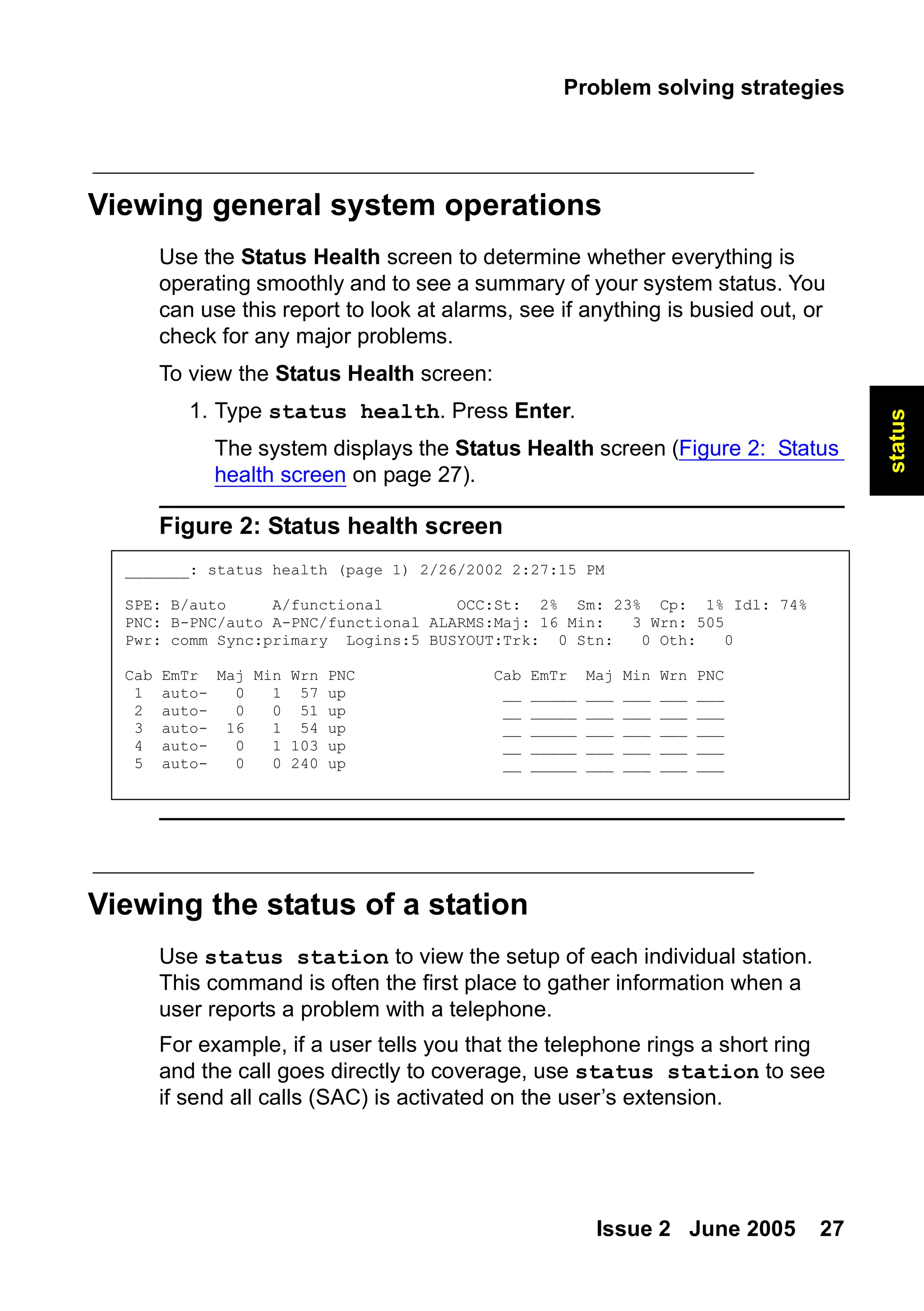
To view the Status Health screen:
1. Type status health. Press Enter.
The system displays the Status Health screen (Figure 2: Status
health screen on page 27).
Figure 2: Status health screen
Viewing the status of a station
Use status station to view the setup of each individual station.
This command is often the first place to gather information when a
user reports a problem with a telephone.
For example, if a user tells you that the telephone rings a short ring
and the call goes directly to coverage, use status station to see
if send all calls (SAC) is activated on the user’s extension.
_______: status health (page 1) 2/26/2002 2:27:15 PM
SPE: B/auto A/functional OCC:St: 2% Sm: 23% Cp: 1% Idl: 74%
PNC: B-PNC/auto A-PNC/functional ALARMS:Maj: 16 Min: 3 Wrn: 505
Pwr: comm Sync:primary Logins:5 BUSYOUT:Trk: 0 Stn: 0 Oth: 0
Cab EmTr Maj Min Wrn PNC Cab EmTr Maj Min Wrn PNC
1 auto- 0 1 57 up __ _____ ___ ___ ___ ___
2 auto- 0 0 51 up __ _____ ___ ___ ___ ___
3 auto- 16 1 54 up __ _____ ___ ___ ___ ___
4 auto- 0 1 103 up __ _____ ___ ___ ___ ___
5 auto- 0 0 240 up __ _____ ___ ___ ___ ___
28.
Checking system status
28Basic Diagnostics Quick Reference
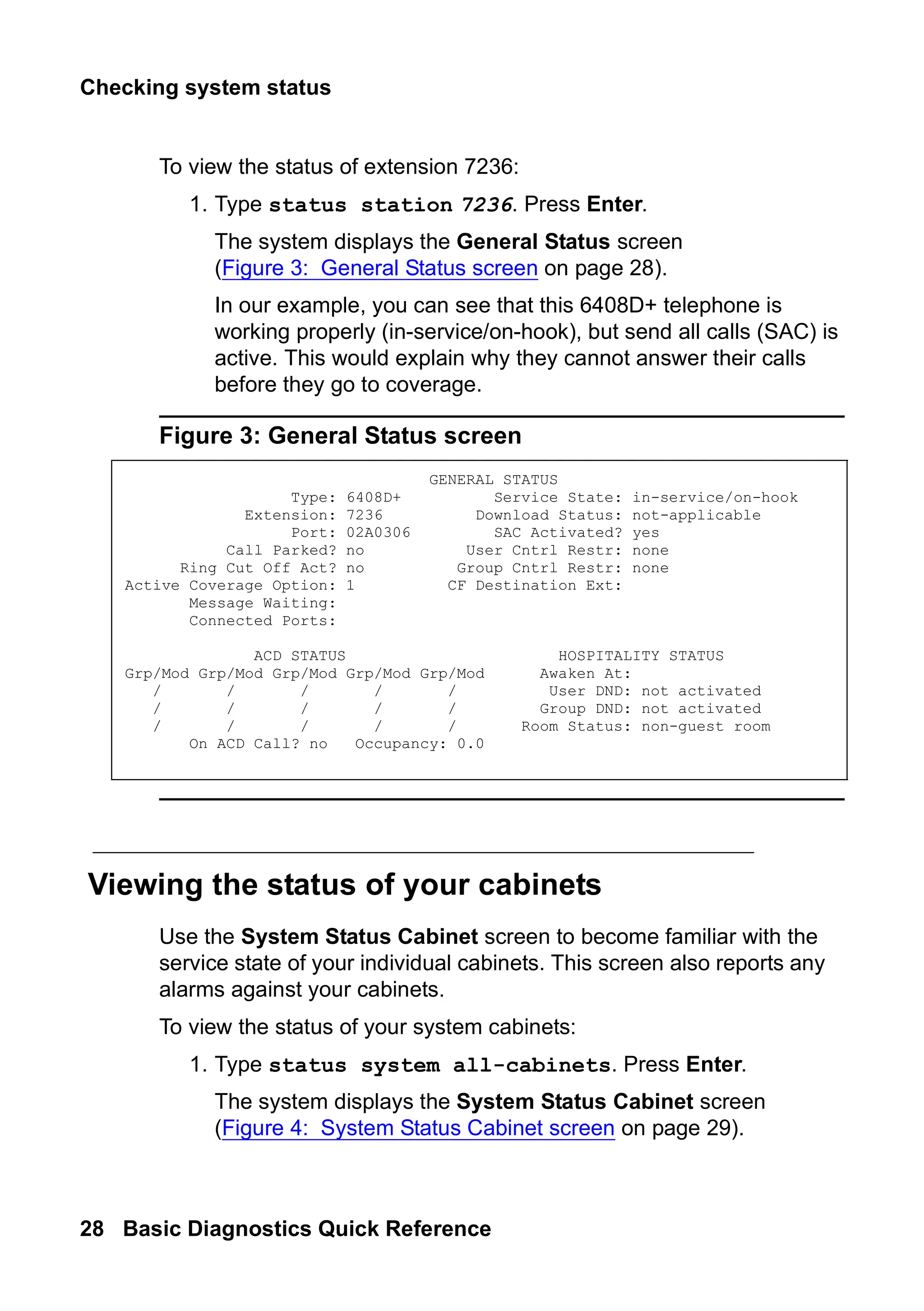
To view the status of extension 7236:
1. Type status station 7236. Press Enter.
The system displays the General Status screen
(Figure 3: General Status screen on page 28).
In our example, you can see that this 6408D+ telephone is
working properly (in-service/on-hook), but send all calls (SAC) is
active. This would explain why they cannot answer their calls
before they go to coverage.
Figure 3: General Status screen
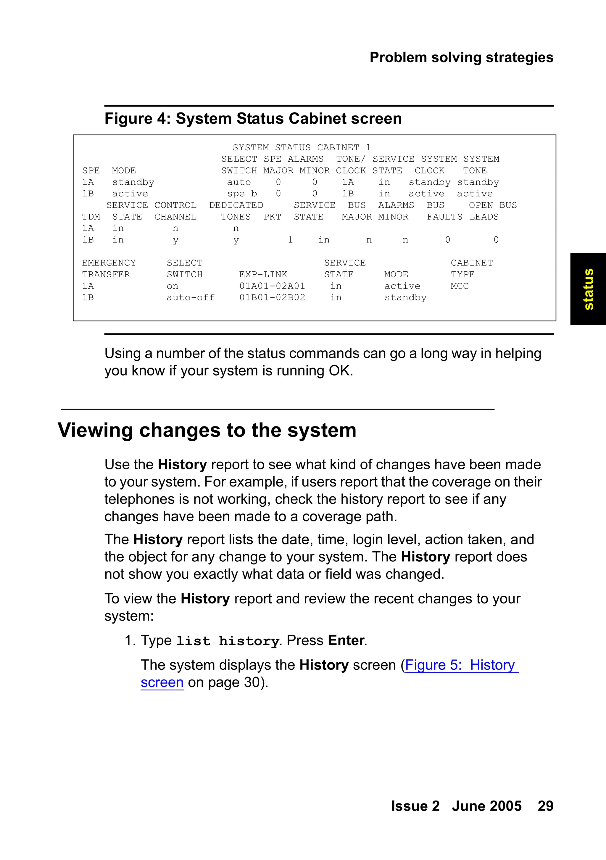
Viewing the status of your cabinets
Use the System Status Cabinet screen to become familiar with the
service state of your individual cabinets. This screen also reports any
alarms against your cabinets.
To view the status of your system cabinets:
1. Type status system all-cabinets. Press Enter.
The system displays the System Status Cabinet screen
(Figure 4: System Status Cabinet screen on page 29).
GENERAL STATUS
Type: 6408D+ Service State: in-service/on-hook
Extension: 7236 Download Status: not-applicable
Port: 02A0306 SAC Activated? yes
Call Parked? no User Cntrl Restr: none
Ring Cut Off Act? no Group Cntrl Restr: none
Active Coverage Option: 1 CF Destination Ext:
Message Waiting:
Connected Ports:
ACD STATUS HOSPITALITY STATUS
Grp/Mod Grp/Mod Grp/Mod Grp/Mod Grp/Mod Awaken At:
/ / / / / User DND: not activated
/ / / / / Group DND: not activated
/ / / / / Room Status: non-guest room
On ACD Call? no Occupancy: 0.0
29.
Problem solving strategies
Issue2 June 2005 29
status
Figure 4: System Status Cabinet screen
Using a number of the status commands can go a long way in helping
you know if your system is running OK.
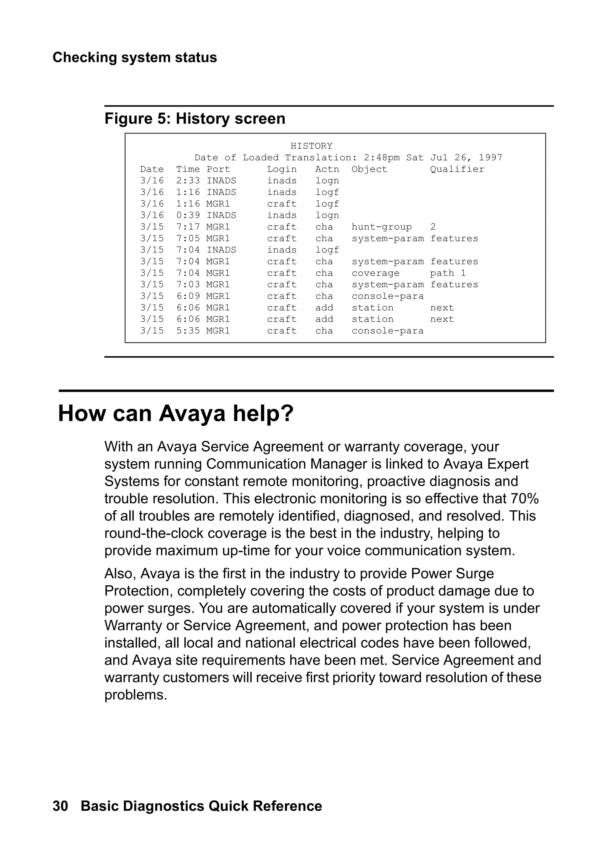
Viewing changes to the system
Use the History report to see what kind of changes have been made
to your system. For example, if users report that the coverage on their
telephones is not working, check the history report to see if any
changes have been made to a coverage path.
The History report lists the date, time, login level, action taken, and
the object for any change to your system. The History report does
not show you exactly what data or field was changed.
To view the History report and review the recent changes to your
system:
1. Type list history. Press Enter.
The system displays the History screen (Figure 5: History
screen on page 30).
SYSTEM STATUS CABINET 1
SELECT SPE ALARMS TONE/ SERVICE SYSTEM SYSTEM
SPE MODE SWITCH MAJOR MINOR CLOCK STATE CLOCK TONE
1A standby auto 0 0 1A in standby standby
1B active spe b 0 0 1B in active active
SERVICE CONTROL DEDICATED SERVICE BUS ALARMS BUS OPEN BUS
TDM STATE CHANNEL TONES PKT STATE MAJOR MINOR FAULTS LEADS
1A in n n
1B in y y 1 in n n 0 0
EMERGENCY SELECT SERVICE CABINET
TRANSFER SWITCH EXP-LINK STATE MODE TYPE
1A on 01A01-02A01 in active MCC
1B auto-off 01B01-02B02 in standby
30.
Checking system status
30Basic Diagnostics Quick Reference
Figure 5: History screen
How can Avaya help?
With an Avaya Service Agreement or warranty coverage, your
system running Communication Manager is linked to Avaya Expert
Systems for constant remote monitoring, proactive diagnosis and
trouble resolution. This electronic monitoring is so effective that 70%
of all troubles are remotely identified, diagnosed, and resolved. This
round-the-clock coverage is the best in the industry, helping to
provide maximum up-time for your voice communication system.
Also, Avaya is the first in the industry to provide Power Surge
Protection, completely covering the costs of product damage due to
power surges. You are automatically covered if your system is under
Warranty or Service Agreement, and power protection has been
installed, all local and national electrical codes have been followed,
and Avaya site requirements have been met. Service Agreement and
warranty customers will receive first priority toward resolution of these
problems.
HISTORY
Date of Loaded Translation: 2:48pm Sat Jul 26, 1997
Date Time Port Login Actn Object Qualifier
3/16 2:33 INADS inads logn
3/16 1:16 INADS inads logf
3/16 1:16 MGR1 craft logf
3/16 0:39 INADS inads logn
3/15 7:17 MGR1 craft cha hunt-group 2
3/15 7:05 MGR1 craft cha system-param features
3/15 7:04 INADS inads logf
3/15 7:04 MGR1 craft cha system-param features
3/15 7:04 MGR1 craft cha coverage path 1
3/15 7:03 MGR1 craft cha system-param features
3/15 6:09 MGR1 craft cha console-para
3/15 6:06 MGR1 craft add station next
3/15 6:06 MGR1 craft add station next
3/15 5:35 MGR1 craft cha console-para
31.
Diagnosing a problem
Issue2 June 2005 31
problem
solving
3: Solving common
problems
This section tells you the questions to ask and the information to
gather to solve some of the most basic telephone problems. It also
describes how to solve common call-center problems.
Diagnosing a problem
As a system administrator, an important part of your job is to respond
to trouble calls from users. You can identify some of the most
common of these problems by following a few simple steps, asking
the right questions, and trying to recreate the problem.
Use a set of questions to determine if:
● the equipment or process has worked before and is now
broken, or if this is a new set-up that you need to correct
● the problem comes from your company’s own equipment, or if
the problem comes from your vendor
● the problem originates within your system, or if the source of the
problem is outside of your own facility
32.
Solving common problems
32Basic Diagnostics Quick Reference
Ask the following basic questions of yourself, your users, and other
system administrators who work with you:
● Is this a new feature or piece of equipment, or did it work before
but does not work now?
● Does the trouble arise when dialing outside the system, dialing
into the system, or dialing inside the system?
● Can we duplicate the problem?
Solving common telephone problems
This section describes the approach that many administrators take to
diagnose and correct common problems with telephones. Following
is a list of suggested actions you can take if you have a problem.
● ask for the exact symptoms
● try to duplicate the problem or have the user show you the
problem
● look at the telephone
● find out if the telephone was swapped out
● check the physical connections (for example, see if the
telephone is plugged in)
● check that the telephone is where it is supposed to be
● try the telephone at another location
● ask if the cord or handset was changed
● check status station
● use display station to look at the station screens
page-by-page
● check the station screens for SAC, coverage paths
● look at printed system records for discrepancies
33.
Solving common telephoneproblems
Issue 2 June 2005 33
problem
solving
● check the alarms and errors logs
● clear any alarms and errors
● test the circuit packs
Let’s take a look at the types of problems users report to their system
administrators, and see how to diagnose and correct the problem.
The user cannot dial out
A user calls to report that the telephone “does not work.” Ask
questions to find out what is really wrong so you can know how to fix
the problem.
To find out why a telephone does not work, ask these questions:
● Does the problem occur when:
- they try to answer a ringing incoming call
- they try to make a call
● If the problem occurs when they try to make a call, is the call
- internal, station to station
- external, to an outside telephone
● Is the problem with just one number, or are they unable to place
any outgoing calls?
● Is this a new telephone, or is this a new problem with an
existing telephone (were they able to call out before)
● Do they hear dial tone before they try to call?
● What do they hear after they dial?
- a tone of some kind
- a message
- static
- nothing
34.
Solving common problems
34Basic Diagnostics Quick Reference
● If they hear a message after they dial, what is the exact
message?
If the message says that the call cannot be completed as dialed,
the problem is likely your ARS programming. For more
information on changing your outbound routing, see the Avaya
Communication Manager Basic Administration Quick Reference,
03-300363.
Incoming calls ring but do not reach the user
Another user calls to report that his telephone “does not work.” Ask
questions similar to the ones listed above. You determine that the
user can call out, and that the telephone rings but there is no call on
the line when the user picks up.
Type status station to see if Send All Calls (SAC) is activated.
The message lamp does not go out
This problem often occurs even when the messages associated with
the telephone have been cleared.
To clear a message waiting light:
1. Type clear amw all n, where n is the extension. Press Enter.
35.
Solving common telephoneproblems
Issue 2 June 2005 35
problem
solving
Diagnosing general trunk problems
The following questions help you determine a problem with a trunk.
● Is the trouble on every call or is the trouble intermittent?
● Are you getting any sort of recordings when you try to dial out
on this trunk?
● Can you identify the trunk in question?
Use a trunk access code (tac) to identify the trunk, especially if
the console has a trunk ID button.
● Is there static on the call?
This is likely a problem with the trunk external to the system.
● Have you notified your vendor of this problem?
Diagnosing tie trunk problems
The following questions help you determine a problem with a tie
trunk.
● Is the problem on incoming calls only?
● Is the problem on outgoing calls only?
● What happens when you try to use this trunk?
● Have you notified the T1 vendor?
● Does this trunk connect to another location?
If so, try to determine the IL number of that location.
● Do you know the circuit ID of this trunk?
36.
Solving common problems
36Basic Diagnostics Quick Reference
Diagnosing modem problems
The following questions help you determine a problem with a modem.
● What is the extension of the modem?
● Is the modem connected through the system?
● What is the modem connected to?
For example, computer, fax, or CMS?
● Have the setup options been changed or checked recently?
● What company manufactures the modem?
● What is the model number?
Diagnosing printer troubles
The following questions help you determine a problem with a printer.
● What is the problem with the printer?
● What is the printer used for?
For example, is it connected to the system, CMS, CAS, or maybe
AUDIX?
● Who manufactures the printer?
● What is the model number?
37.
Solving call centerproblems
Issue 2 June 2005 37
problem
solving
Diagnosing password, login, and
terminal access problems
If the problem is with remote dial-in access, ask:
● How do you dial in?
● What type of software or dialing program do you use?
● What error messages do you see when you try to dial in?
If your password expired, is not working, or is incorrect, call Avaya for
assistance in getting the issue resolved.
Diagnosing SAT problems
If the problem is with the System Access Terminal (SAT), ask:
● What type of terminal is it?
● What type of trouble are you having?
Solving call center problems
This section helps you identify and solve common problems affecting
hunt groups, splits, announcements, and caller access.
The tables below describe symptoms and solutions for common
problems in call centers not using ACD or call vectoring.
38.
Solving common problems
38Basic Diagnostics Quick Reference
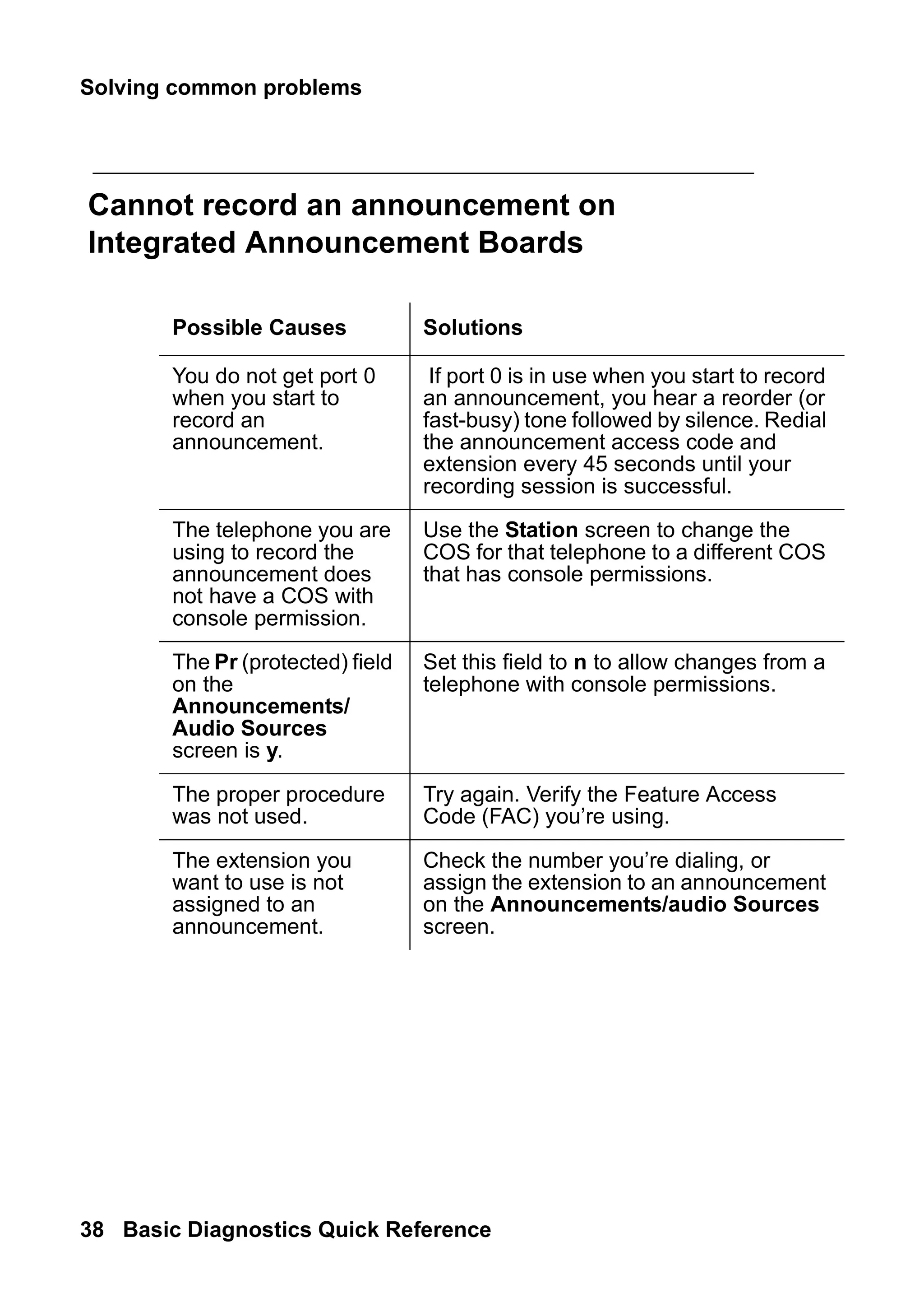
Cannot record an announcement on
Integrated Announcement Boards
Possible Causes Solutions
You do not get port 0
when you start to
record an
announcement.
If port 0 is in use when you start to record
an announcement, you hear a reorder (or
fast-busy) tone followed by silence. Redial
the announcement access code and
extension every 45 seconds until your
recording session is successful.
The telephone you are
using to record the
announcement does
not have a COS with
console permission.
Use the Station screen to change the
COS for that telephone to a different COS
that has console permissions.
The Pr (protected) field
on the
Announcements/
Audio Sources
screen is y.
Set this field to n to allow changes from a
telephone with console permissions.
The proper procedure
was not used.
Try again. Verify the Feature Access
Code (FAC) you’re using.
The extension you
want to use is not
assigned to an
announcement.
Check the number you’re dialing, or
assign the extension to an announcement
on the Announcements/audio Sources
screen.
39.
Solving call centerproblems
Issue 2 June 2005 39
problem
solving
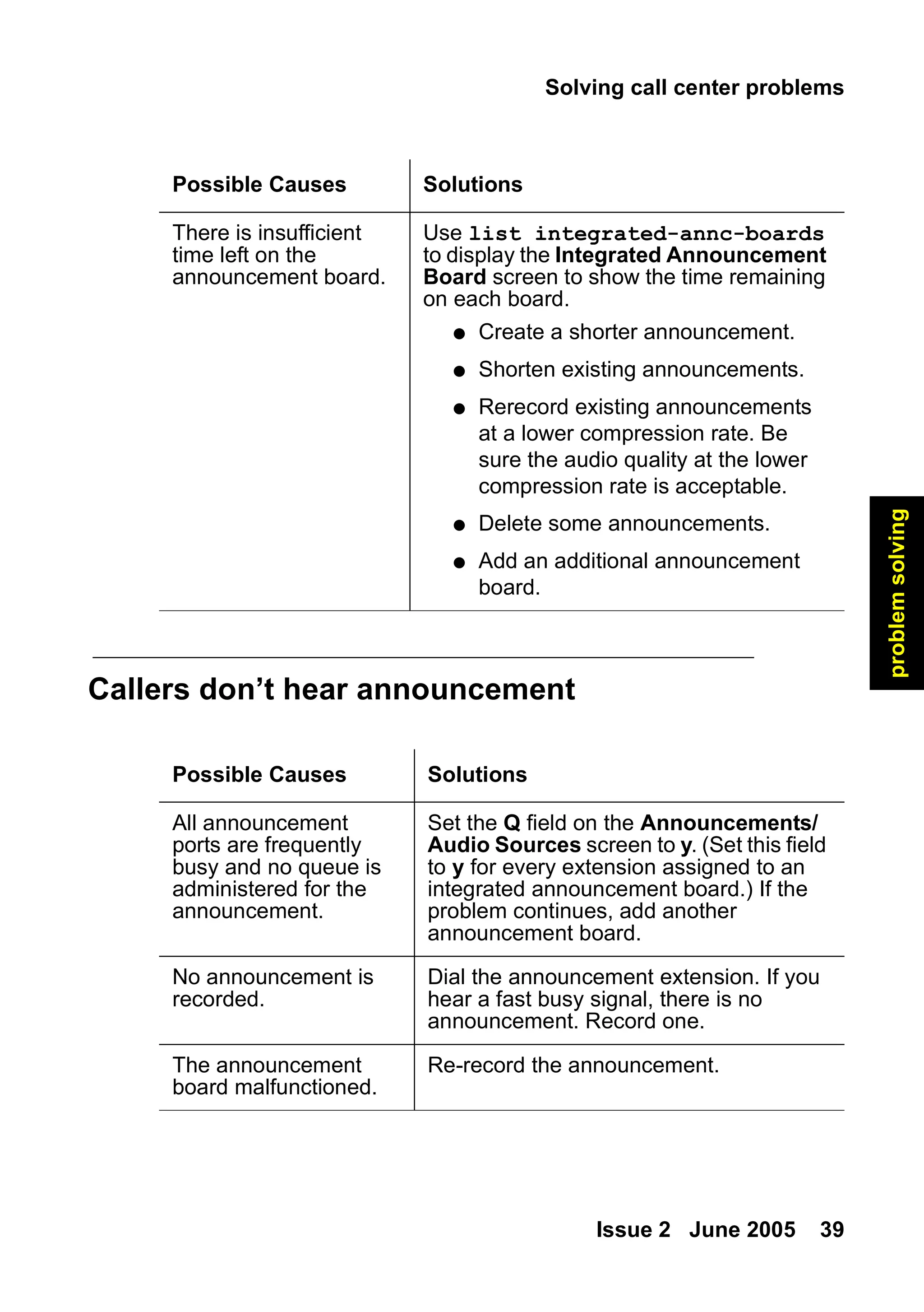
Callers don’t hear announcement
There is insufficient
time left on the
announcement board.
Use list integrated-annc-boards
to display the Integrated Announcement
Board screen to show the time remaining
on each board.
● Create a shorter announcement.
● Shorten existing announcements.
● Rerecord existing announcements
at a lower compression rate. Be
sure the audio quality at the lower
compression rate is acceptable.
● Delete some announcements.
● Add an additional announcement
board.
Possible Causes Solutions
Possible Causes Solutions
All announcement
ports are frequently
busy and no queue is
administered for the
announcement.
Set the Q field on the Announcements/
Audio Sources screen to y. (Set this field
to y for every extension assigned to an
integrated announcement board.) If the
problem continues, add another
announcement board.
No announcement is
recorded.
Dial the announcement extension. If you
hear a fast busy signal, there is no
announcement. Record one.
The announcement
board malfunctioned.
Re-record the announcement.
40.
Solving common problems
40Basic Diagnostics Quick Reference
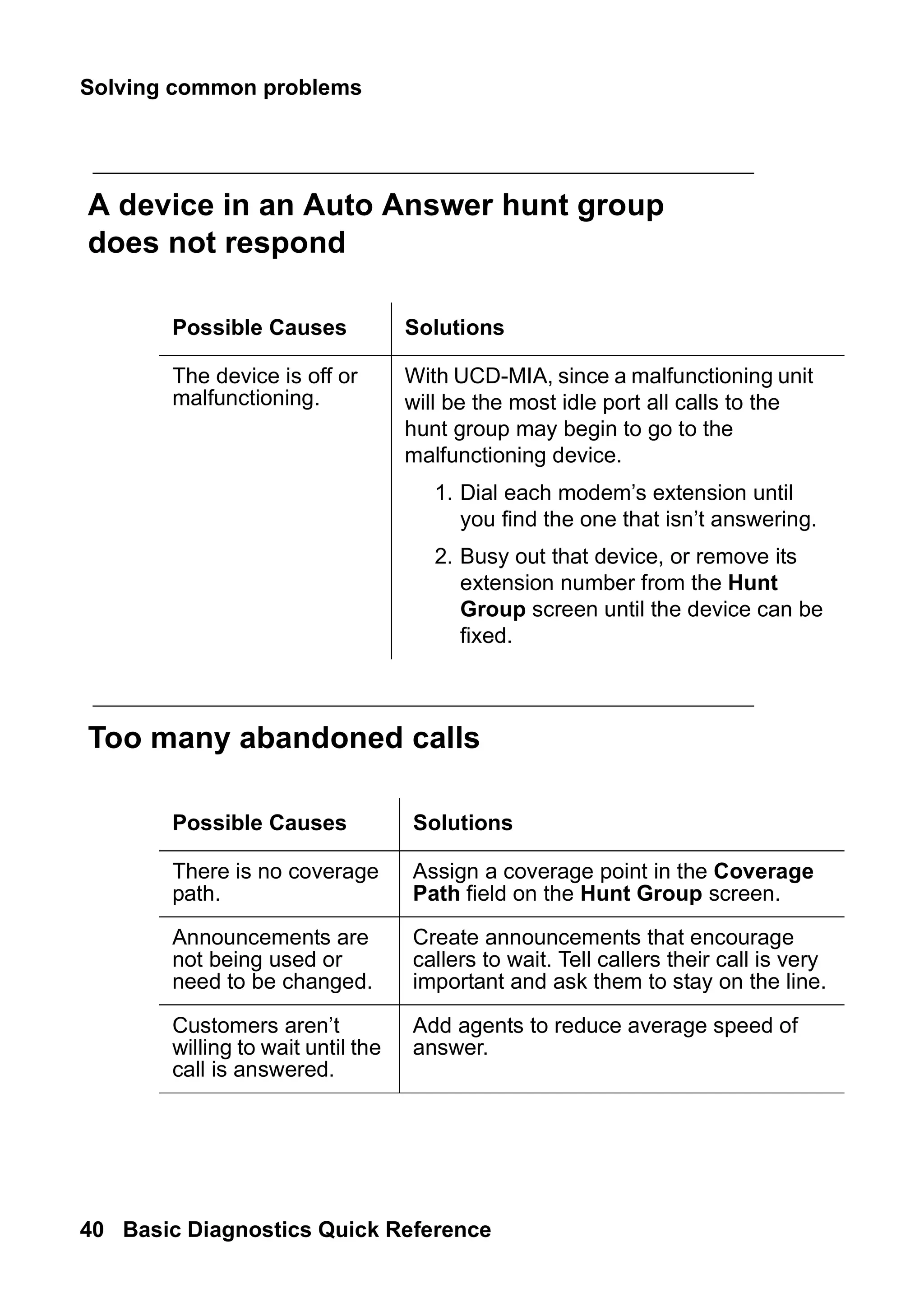
A device in an Auto Answer hunt group
does not respond
Too many abandoned calls
Possible Causes Solutions
The device is off or
malfunctioning.
With UCD-MIA, since a malfunctioning unit
will be the most idle port all calls to the
hunt group may begin to go to the
malfunctioning device.
1. Dial each modem’s extension until
you find the one that isn’t answering.
2. Busy out that device, or remove its
extension number from the Hunt
Group screen until the device can be
fixed.
Possible Causes Solutions
There is no coverage
path.
Assign a coverage point in the Coverage
Path field on the Hunt Group screen.
Announcements are
not being used or
need to be changed.
Create announcements that encourage
callers to wait. Tell callers their call is very
important and ask them to stay on the line.
Customers aren’t
willing to wait until the
call is answered.
Add agents to reduce average speed of
answer.
41.
Solving call centerproblems
Issue 2 June 2005 41
problem
solving
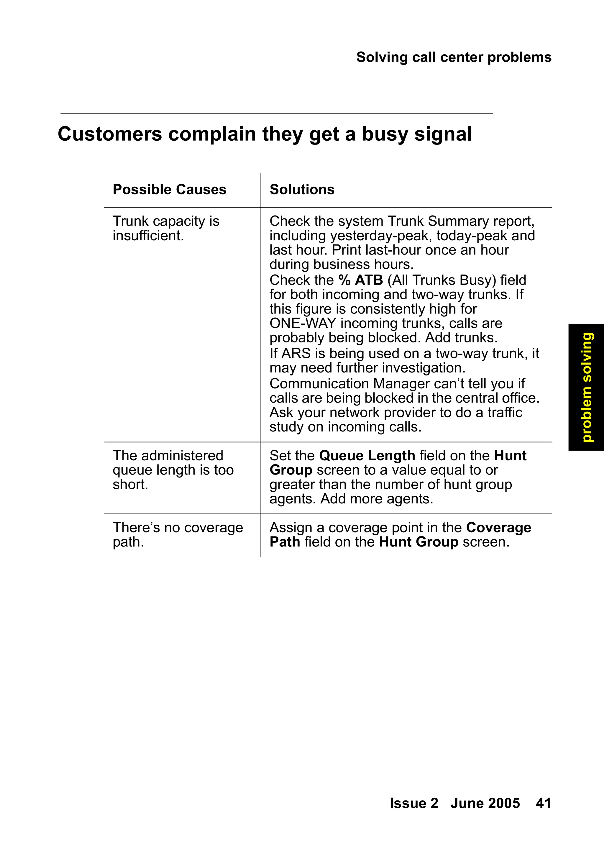
Customers complain they get a busy signal
Possible Causes Solutions
Trunk capacity is
insufficient.
Check the system Trunk Summary report,
including yesterday-peak, today-peak and
last hour. Print last-hour once an hour
during business hours.
Check the % ATB (All Trunks Busy) field
for both incoming and two-way trunks. If
this figure is consistently high for
ONE-WAY incoming trunks, calls are
probably being blocked. Add trunks.
If ARS is being used on a two-way trunk, it
may need further investigation.
Communication Manager can’t tell you if
calls are being blocked in the central office.
Ask your network provider to do a traffic
study on incoming calls.
The administered
queue length is too
short.
Set the Queue Length field on the Hunt
Group screen to a value equal to or
greater than the number of hunt group
agents. Add more agents.
There’s no coverage
path.
Assign a coverage point in the Coverage
Path field on the Hunt Group screen.
Maintenance reports
Issue 2June 2005 43
alarms
/
errors
4: Alarms and errors
This section is for adventurous administrators who are curious about
how to diagnose and fix common problems. The information here will
help you understand how to read and interpret:
● error logs
● alarm logs
Maintenance reports
Avaya Communication Manager monitors many system components.
When a component fails or performs unacceptably, the subsystem
generates two kinds of reports:
● detailed reports in the error log
● general reports in the alarm log
The system detects error conditions in its components through
Maintenance Objects (MO). MOs are the software modules that
monitor, test, and report possible fault conditions.
Viewing error logs
It is a good idea to run and inspect error logs on a regular basis. You
can view all active system errors on the error log. You can also
specify a particular component of your system or a certain time period
to be reported on the error log.
44.
Alarms and errors
44Basic Diagnostics Quick Reference
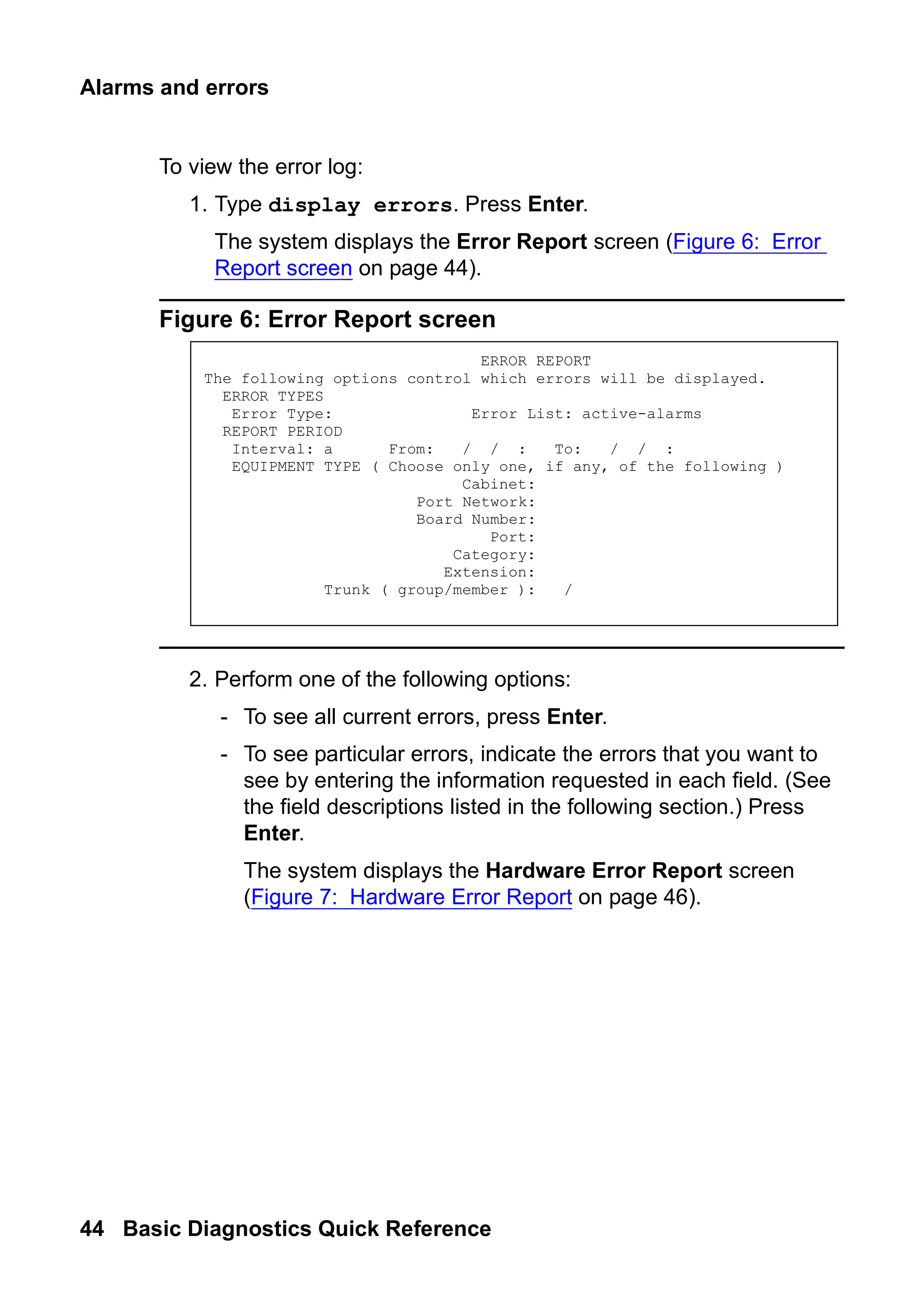
To view the error log:
1. Type display errors. Press Enter.
The system displays the Error Report screen (Figure 6: Error
Report screen on page 44).
Figure 6: Error Report screen
2. Perform one of the following options:
- To see all current errors, press Enter.
- To see particular errors, indicate the errors that you want to
see by entering the information requested in each field. (See
the field descriptions listed in the following section.) Press
Enter.
The system displays the Hardware Error Report screen
(Figure 7: Hardware Error Report on page 46).
ERROR REPORT
The following options control which errors will be displayed.
ERROR TYPES
Error Type: Error List: active-alarms
REPORT PERIOD
Interval: a From: / / : To: / / :
EQUIPMENT TYPE ( Choose only one, if any, of the following )
Cabinet:
Port Network:
Board Number:
Port:
Category:
Extension:
Trunk ( group/member ): /
45.
Maintenance reports
Issue 2June 2005 45
alarms
/
errors
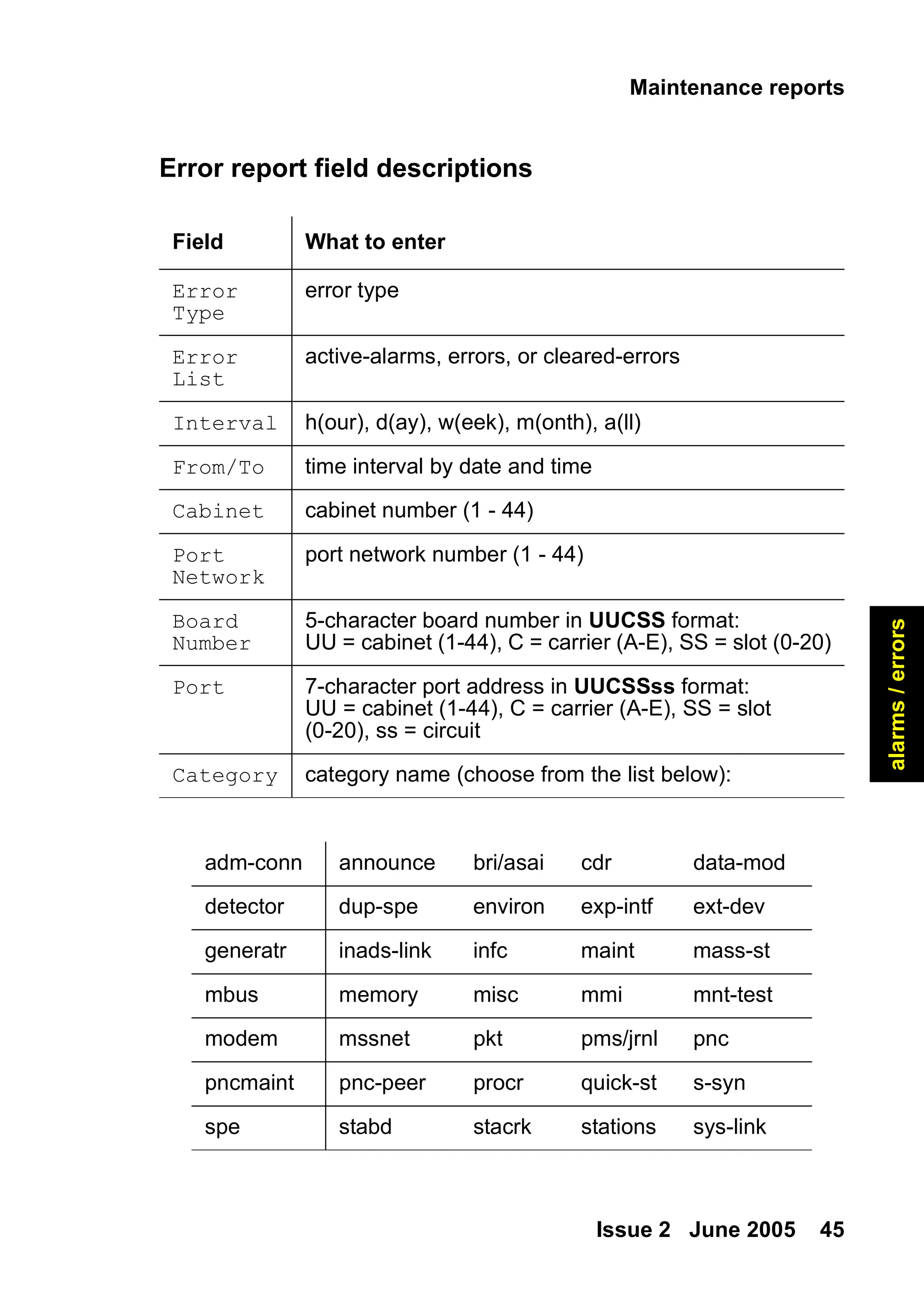
Error report field descriptions
Field What to enter
Error
Type
error type
Error
List
active-alarms, errors, or cleared-errors
Interval h(our), d(ay), w(eek), m(onth), a(ll)
From/To time interval by date and time
Cabinet cabinet number (1 - 44)
Port
Network
port network number (1 - 44)
Board
Number
5-character board number in UUCSS format:
UU = cabinet (1-44), C = carrier (A-E), SS = slot (0-20)
Port 7-character port address in UUCSSss format:
UU = cabinet (1-44), C = carrier (A-E), SS = slot
(0-20), ss = circuit
Category category name (choose from the list below):
adm-conn announce bri/asai cdr data-mod
detector dup-spe environ exp-intf ext-dev
generatr inads-link infc maint mass-st
mbus memory misc mmi mnt-test
modem mssnet pkt pms/jrnl pnc
pncmaint pnc-peer procr quick-st s-syn
spe stabd stacrk stations sys-link
46.
Alarms and errors
46Basic Diagnostics Quick Reference
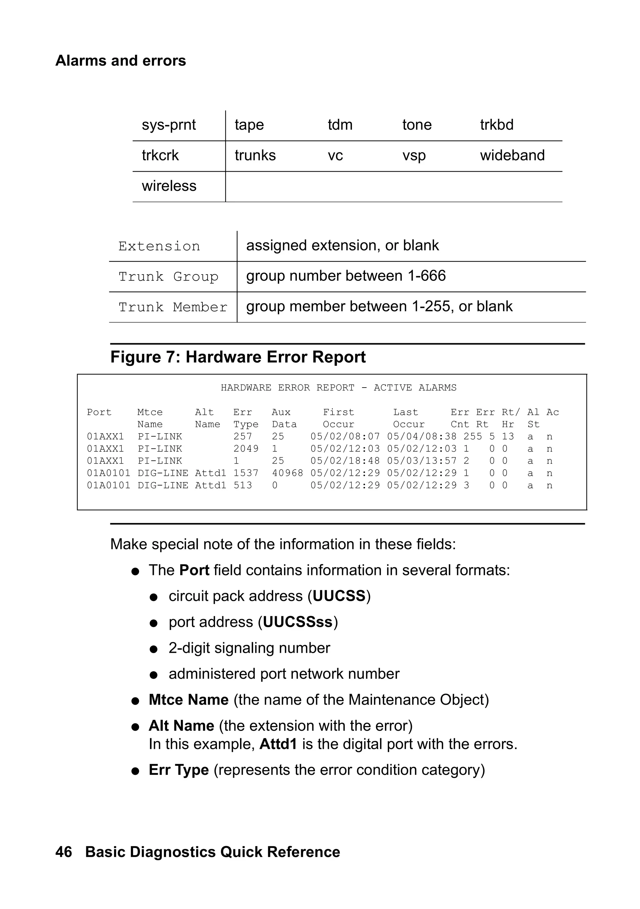
Figure 7: Hardware Error Report
Make special note of the information in these fields:
● The Port field contains information in several formats:
● circuit pack address (UUCSS)
● port address (UUCSSss)
● 2-digit signaling number
● administered port network number
● Mtce Name (the name of the Maintenance Object)
● Alt Name (the extension with the error)
In this example, Attd1 is the digital port with the errors.
● Err Type (represents the error condition category)
sys-prnt tape tdm tone trkbd
trkcrk trunks vc vsp wideband
wireless
Extension assigned extension, or blank
Trunk Group group number between 1-666
Trunk Member group member between 1-255, or blank
HARDWARE ERROR REPORT - ACTIVE ALARMS
Port Mtce Alt Err Aux First Last Err Err Rt/ Al Ac
Name Name Type Data Occur Occur Cnt Rt Hr St
01AXX1 PI-LINK 257 25 05/02/08:07 05/04/08:38 255 5 13 a n
01AXX1 PI-LINK 2049 1 05/02/12:03 05/02/12:03 1 0 0 a n
01AXX1 PI-LINK 1 25 05/02/18:48 05/03/13:57 2 0 0 a n
01A0101 DIG-LINE Attd1 1537 40968 05/02/12:29 05/02/12:29 1 0 0 a n
01A0101 DIG-LINE Attd1 513 0 05/02/12:29 05/02/12:29 3 0 0 a n
47.
Maintenance reports
Issue 2June 2005 47
alarms
/
errors
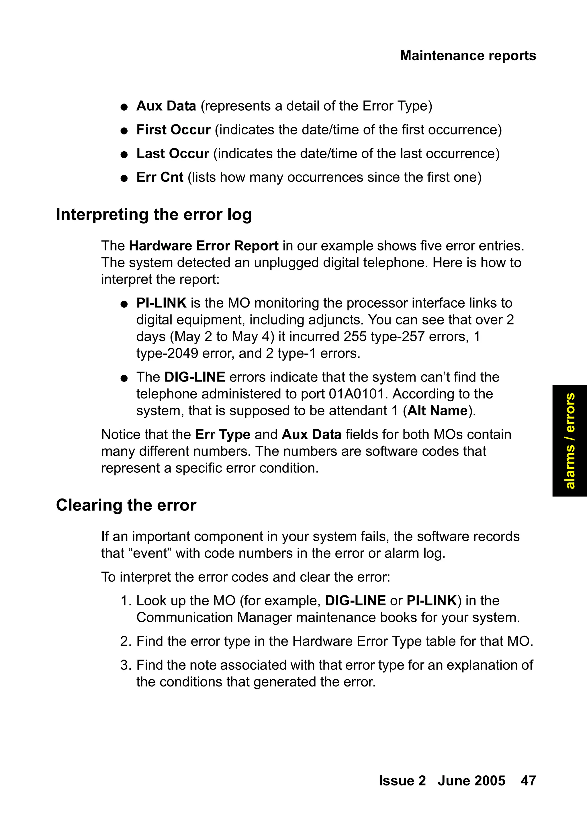
● Aux Data (represents a detail of the Error Type)
● First Occur (indicates the date/time of the first occurrence)
● Last Occur (indicates the date/time of the last occurrence)
● Err Cnt (lists how many occurrences since the first one)
Interpreting the error log
The Hardware Error Report in our example shows five error entries.
The system detected an unplugged digital telephone. Here is how to
interpret the report:
● PI-LINK is the MO monitoring the processor interface links to
digital equipment, including adjuncts. You can see that over 2
days (May 2 to May 4) it incurred 255 type-257 errors, 1
type-2049 error, and 2 type-1 errors.
● The DIG-LINE errors indicate that the system can’t find the
telephone administered to port 01A0101. According to the
system, that is supposed to be attendant 1 (Alt Name).
Notice that the Err Type and Aux Data fields for both MOs contain
many different numbers. The numbers are software codes that
represent a specific error condition.
Clearing the error
If an important component in your system fails, the software records
that “event” with code numbers in the error or alarm log.
To interpret the error codes and clear the error:
1. Look up the MO (for example, DIG-LINE or PI-LINK) in the
Communication Manager maintenance books for your system.
2. Find the error type in the Hardware Error Type table for that MO.
3. Find the note associated with that error type for an explanation of
the conditions that generated the error.
48.
Alarms and errors
48Basic Diagnostics Quick Reference
4. Perform the recommended procedure to clear the error.
The recommended procedure may require you to test alarmed
components. Be sure to have test permissions enabled.
If any tests fail or abort, you will get an error code for the test.
5. Look up the test error code by MO in your Communication
Manager maintenance books.
6. Find the numbered test listed in the test results.
7. Look for the correct combination of error code and test result in
the numbered-test tables.
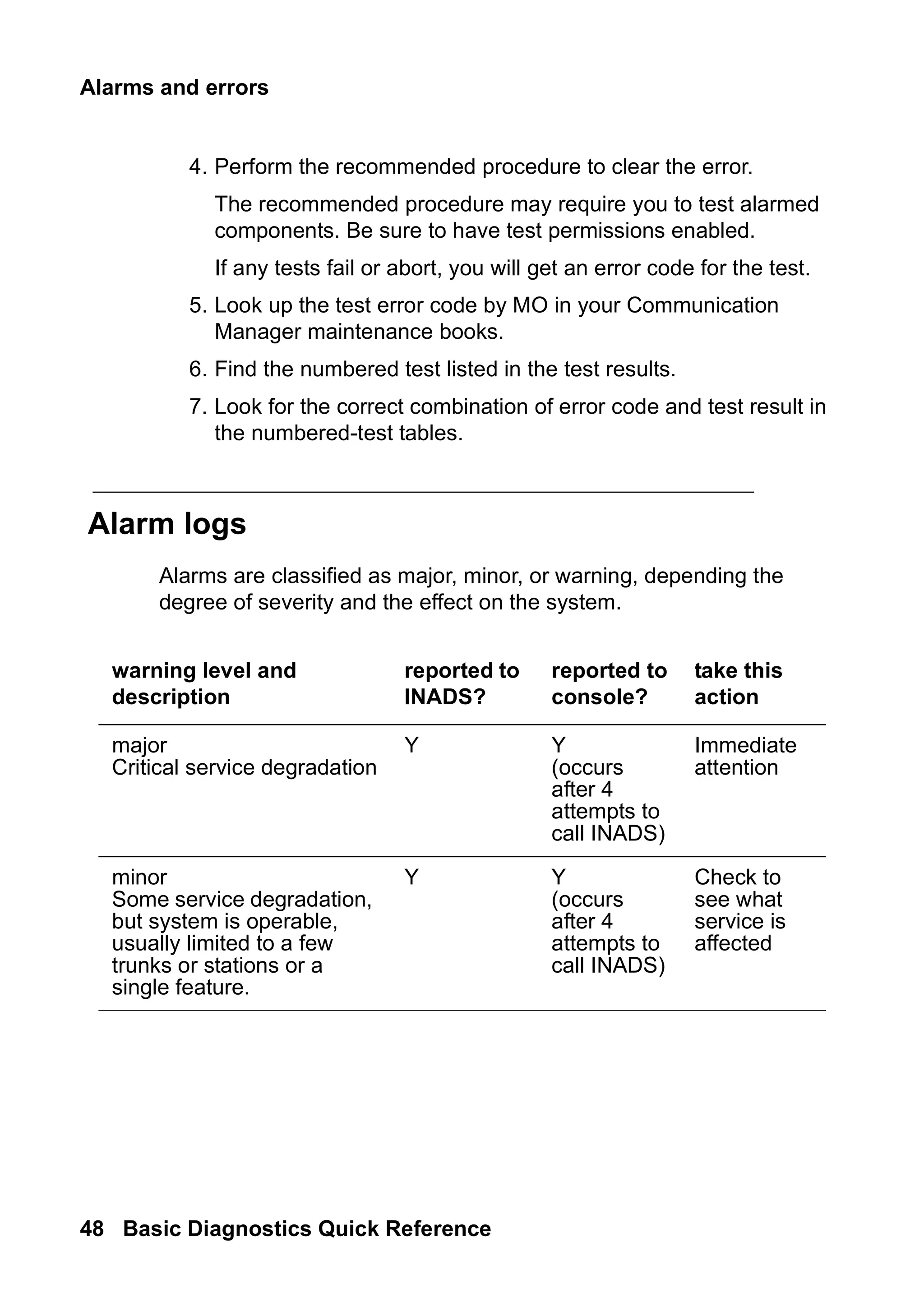
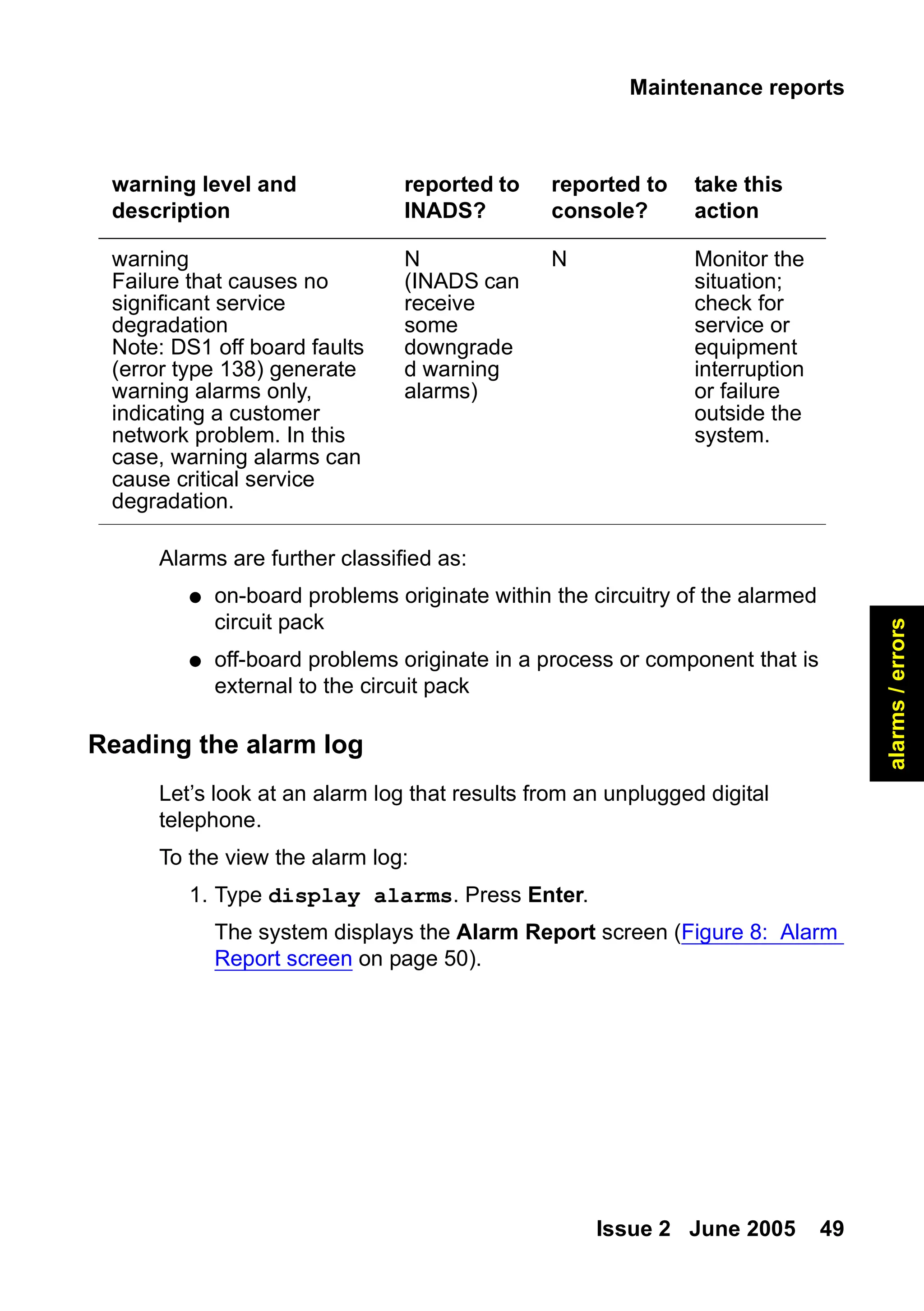
Alarm logs
Alarms are classified as major, minor, or warning, depending the
degree of severity and the effect on the system.
warning level and
description
reported to
INADS?
reported to
console?
take this
action
major
Critical service degradation
Y Y
(occurs
after 4
attempts to
call INADS)
Immediate
attention
minor
Some service degradation,
but system is operable,
usually limited to a few
trunks or stations or a
single feature.
Y Y
(occurs
after 4
attempts to
call INADS)
Check to
see what
service is
affected
49.
Maintenance reports
Issue 2June 2005 49
alarms
/
errors
Alarms are further classified as:
● on-board problems originate within the circuitry of the alarmed
circuit pack
● off-board problems originate in a process or component that is
external to the circuit pack
Reading the alarm log
Let’s look at an alarm log that results from an unplugged digital
telephone.
To the view the alarm log:
1. Type display alarms. Press Enter.
The system displays the Alarm Report screen (Figure 8: Alarm
Report screen on page 50).
warning
Failure that causes no
significant service
degradation
Note: DS1 off board faults
(error type 138) generate
warning alarms only,
indicating a customer
network problem. In this
case, warning alarms can
cause critical service
degradation.
N
(INADS can
receive
some
downgrade
d warning
alarms)
N Monitor the
situation;
check for
service or
equipment
interruption
or failure
outside the
system.
warning level and
description
reported to
INADS?
reported to
console?
take this
action
50.
Alarms and errors
50Basic Diagnostics Quick Reference
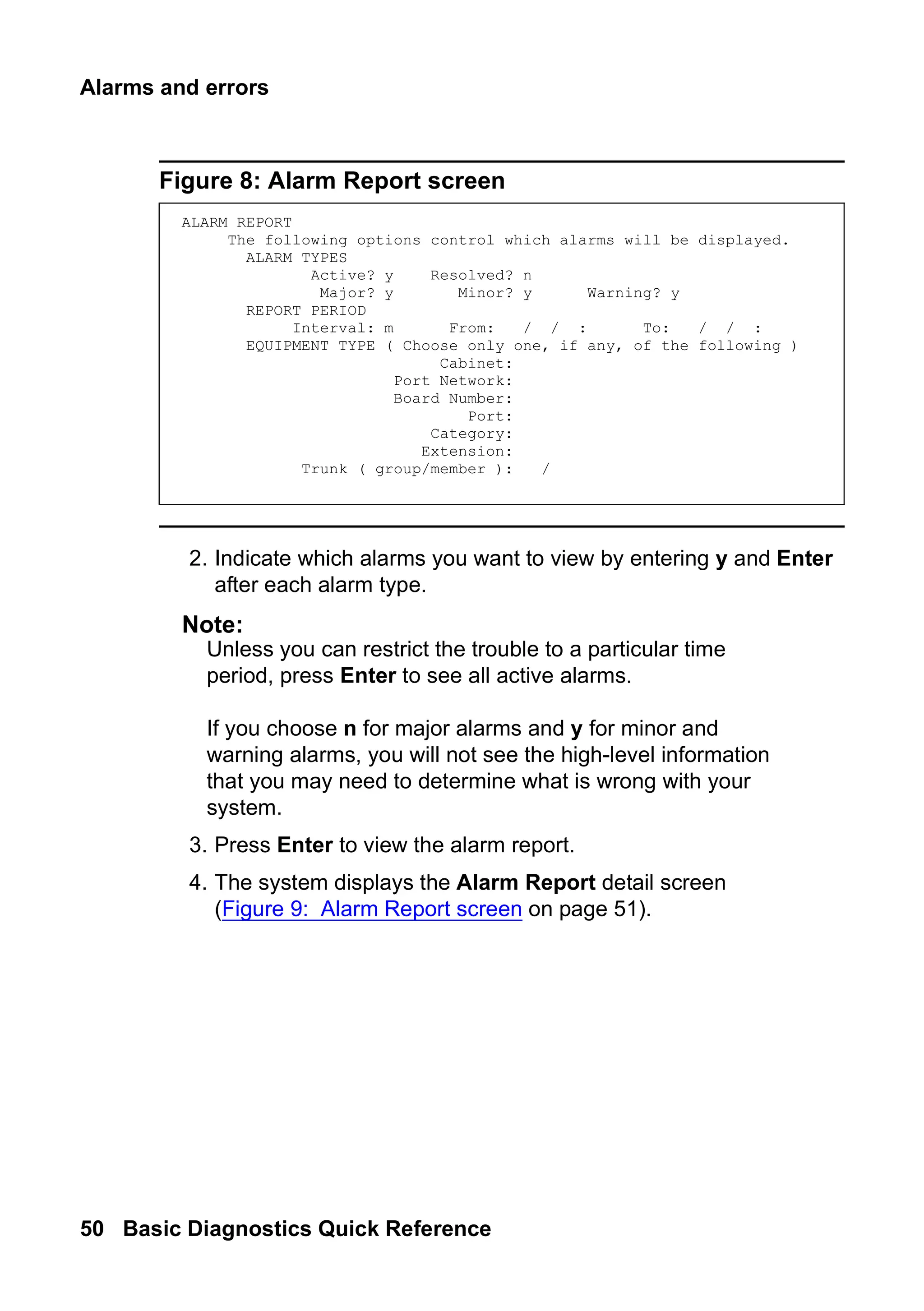
Figure 8: Alarm Report screen
2. Indicate which alarms you want to view by entering y and Enter
after each alarm type.
Note:
Note: Unless you can restrict the trouble to a particular time
period, press Enter to see all active alarms.
If you choose n for major alarms and y for minor and
warning alarms, you will not see the high-level information
that you may need to determine what is wrong with your
system.
3. Press Enter to view the alarm report.
4. The system displays the Alarm Report detail screen
(Figure 9: Alarm Report screen on page 51).
ALARM REPORT
The following options control which alarms will be displayed.
ALARM TYPES
Active? y Resolved? n
Major? y Minor? y Warning? y
REPORT PERIOD
Interval: m From: / / : To: / / :
EQUIPMENT TYPE ( Choose only one, if any, of the following )
Cabinet:
Port Network:
Board Number:
Port:
Category:
Extension:
Trunk ( group/member ): /
51.
Maintenance reports
Issue 2June 2005 51
alarms
/
errors
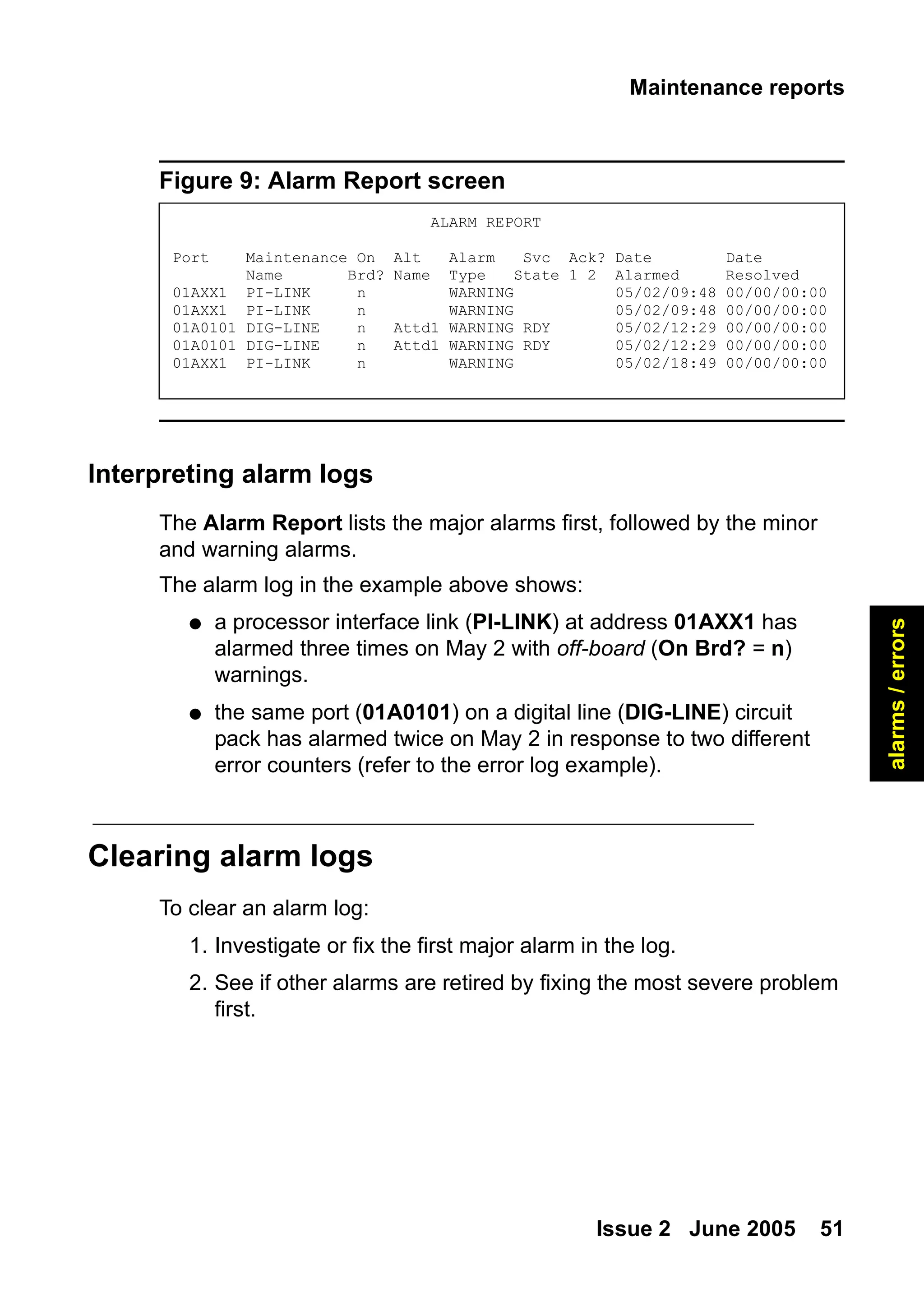
Figure 9: Alarm Report screen
Interpreting alarm logs
The Alarm Report lists the major alarms first, followed by the minor
and warning alarms.
The alarm log in the example above shows:
● a processor interface link (PI-LINK) at address 01AXX1 has
alarmed three times on May 2 with off-board (On Brd? = n)
warnings.
● the same port (01A0101) on a digital line (DIG-LINE) circuit
pack has alarmed twice on May 2 in response to two different
error counters (refer to the error log example).
Clearing alarm logs
To clear an alarm log:
1. Investigate or fix the first major alarm in the log.
2. See if other alarms are retired by fixing the most severe problem
first.
ALARM REPORT
Port Maintenance On Alt Alarm Svc Ack? Date Date
Name Brd? Name Type State 1 2 Alarmed Resolved
01AXX1 PI-LINK n WARNING 05/02/09:48 00/00/00:00
01AXX1 PI-LINK n WARNING 05/02/09:48 00/00/00:00
01A0101 DIG-LINE n Attd1 WARNING RDY 05/02/12:29 00/00/00:00
01A0101 DIG-LINE n Attd1 WARNING RDY 05/02/12:29 00/00/00:00
01AXX1 PI-LINK n WARNING 05/02/18:49 00/00/00:00
52.
Alarms and errors
52Basic Diagnostics Quick Reference
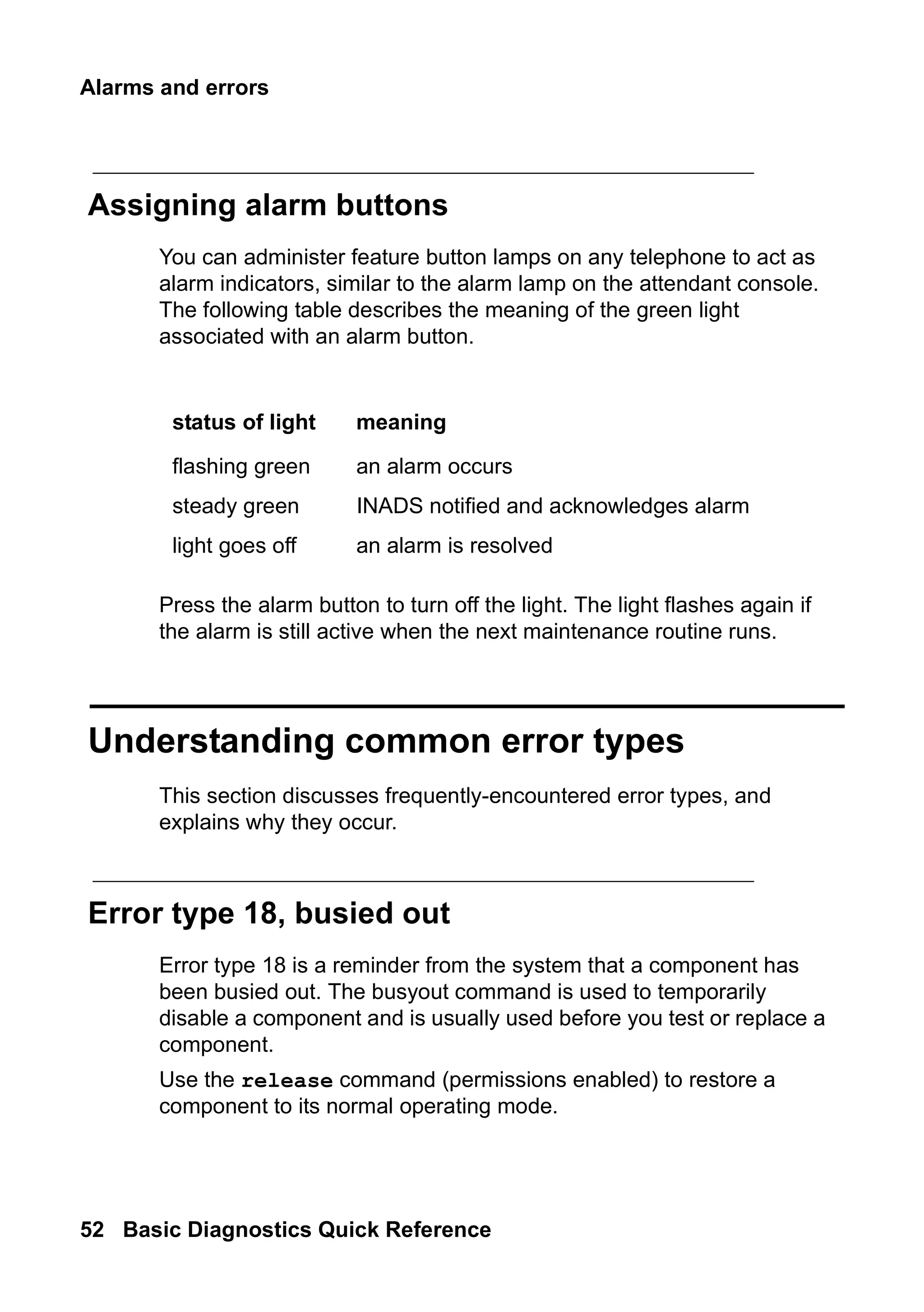
Assigning alarm buttons
You can administer feature button lamps on any telephone to act as
alarm indicators, similar to the alarm lamp on the attendant console.
The following table describes the meaning of the green light
associated with an alarm button.
Press the alarm button to turn off the light. The light flashes again if
the alarm is still active when the next maintenance routine runs.
Understanding common error types
This section discusses frequently-encountered error types, and
explains why they occur.
Error type 18, busied out
Error type 18 is a reminder from the system that a component has
been busied out. The busyout command is used to temporarily
disable a component and is usually used before you test or replace a
component.
Use the release command (permissions enabled) to restore a
component to its normal operating mode.
status of light meaning
flashing green an alarm occurs
steady green INADS notified and acknowledges alarm
light goes off an alarm is resolved
53.
Understanding common errortypes
Issue 2 June 2005 53
alarms
/
errors
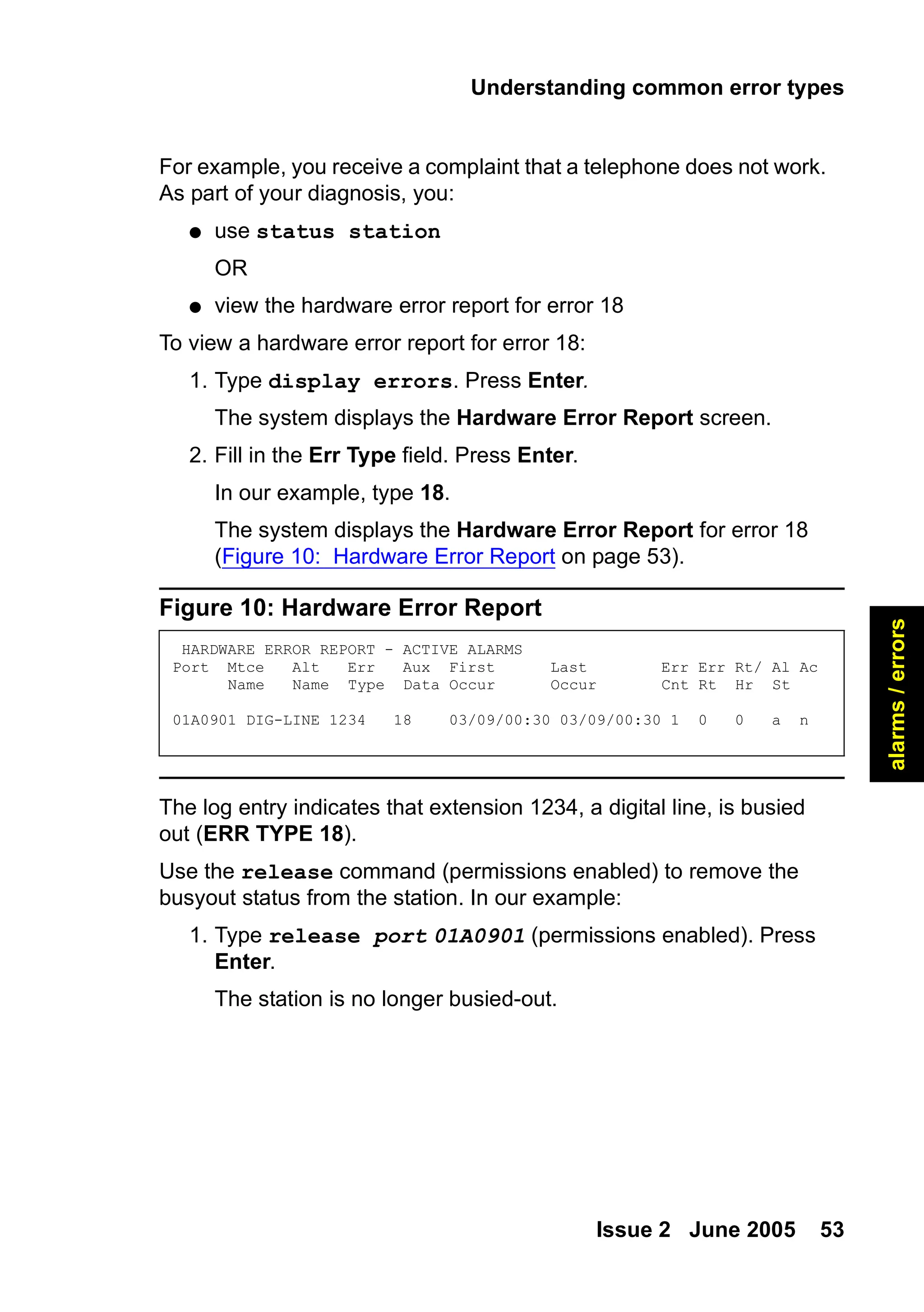
For example, you receive a complaint that a telephone does not work.
As part of your diagnosis, you:
● use status station
OR
● view the hardware error report for error 18
To view a hardware error report for error 18:
1. Type display errors. Press Enter.
The system displays the Hardware Error Report screen.
2. Fill in the Err Type field. Press Enter.
In our example, type 18.
The system displays the Hardware Error Report for error 18
(Figure 10: Hardware Error Report on page 53).
Figure 10: Hardware Error Report
The log entry indicates that extension 1234, a digital line, is busied
out (ERR TYPE 18).
Use the release command (permissions enabled) to remove the
busyout status from the station. In our example:
1. Type release port 01A0901 (permissions enabled). Press
Enter.
The station is no longer busied-out.
HARDWARE ERROR REPORT - ACTIVE ALARMS
Port Mtce Alt Err Aux First Last Err Err Rt/ Al Ac
Name Name Type Data Occur Occur Cnt Rt Hr St
01A0901 DIG-LINE 1234 18 03/09/00:30 03/09/00:30 1 0 0 a n
54.
Alarms and errors
54Basic Diagnostics Quick Reference
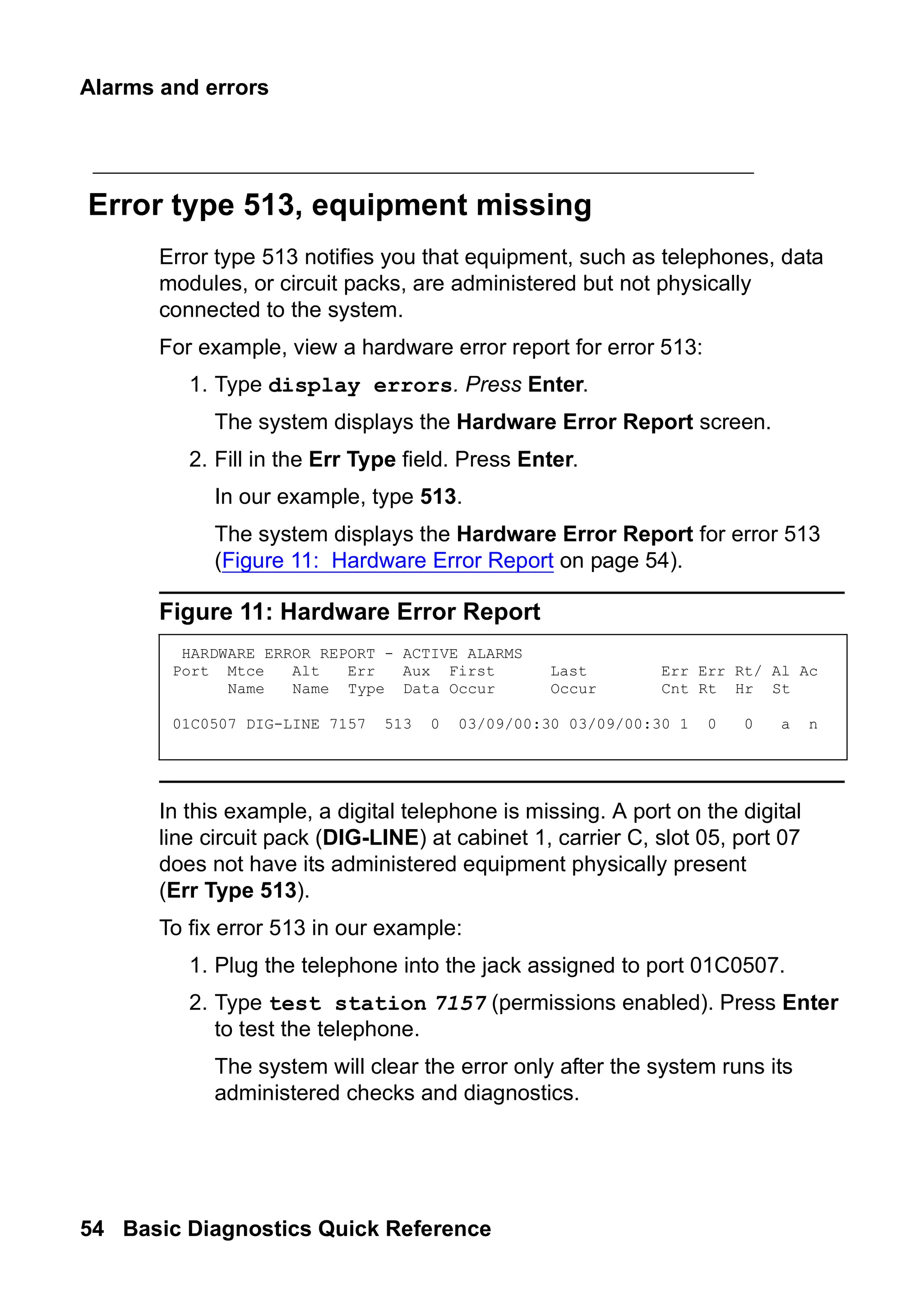
Error type 513, equipment missing
Error type 513 notifies you that equipment, such as telephones, data
modules, or circuit packs, are administered but not physically
connected to the system.
For example, view a hardware error report for error 513:
1. Type display errors. Press Enter.
The system displays the Hardware Error Report screen.
2. Fill in the Err Type field. Press Enter.
In our example, type 513.
The system displays the Hardware Error Report for error 513
(Figure 11: Hardware Error Report on page 54).
Figure 11: Hardware Error Report
In this example, a digital telephone is missing. A port on the digital
line circuit pack (DIG-LINE) at cabinet 1, carrier C, slot 05, port 07
does not have its administered equipment physically present
(Err Type 513).
To fix error 513 in our example:
1. Plug the telephone into the jack assigned to port 01C0507.
2. Type test station 7157 (permissions enabled). Press Enter
to test the telephone.
The system will clear the error only after the system runs its
administered checks and diagnostics.
HARDWARE ERROR REPORT - ACTIVE ALARMS
Port Mtce Alt Err Aux First Last Err Err Rt/ Al Ac
Name Name Type Data Occur Occur Cnt Rt Hr St
01C0507 DIG-LINE 7157 513 0 03/09/00:30 03/09/00:30 1 0 0 a n
55.
Preventing alarms anderrors
Issue 2 June 2005 55
alarms
/
errors
Error type 1, circuit pack removed
Error type 1 often indicates that an administered circuit pack has
been removed.
To correct the problem and clear Error type 1:
1. Replace and latch the circuit pack in its administered slot.
The next time the system runs its routine maintenance program,
it should be able to “see” the circuit pack and the error will not
appear.
Preventing alarms and errors
This section lists a few common causes of unnecessary alarms.
Turn off maintenance
The Remote Loop-Around Test sends a burst of current to activate a
telephone’s ringer. If the ringer responds, the test detects the return.
Data modules, fax machines and modems do not have ringers and do
not respond to this test. This generates an error on that port.
You should turn off this test for data modules, fax machines and
modems. Turning off the test does not affect the performance of any
of these devices.
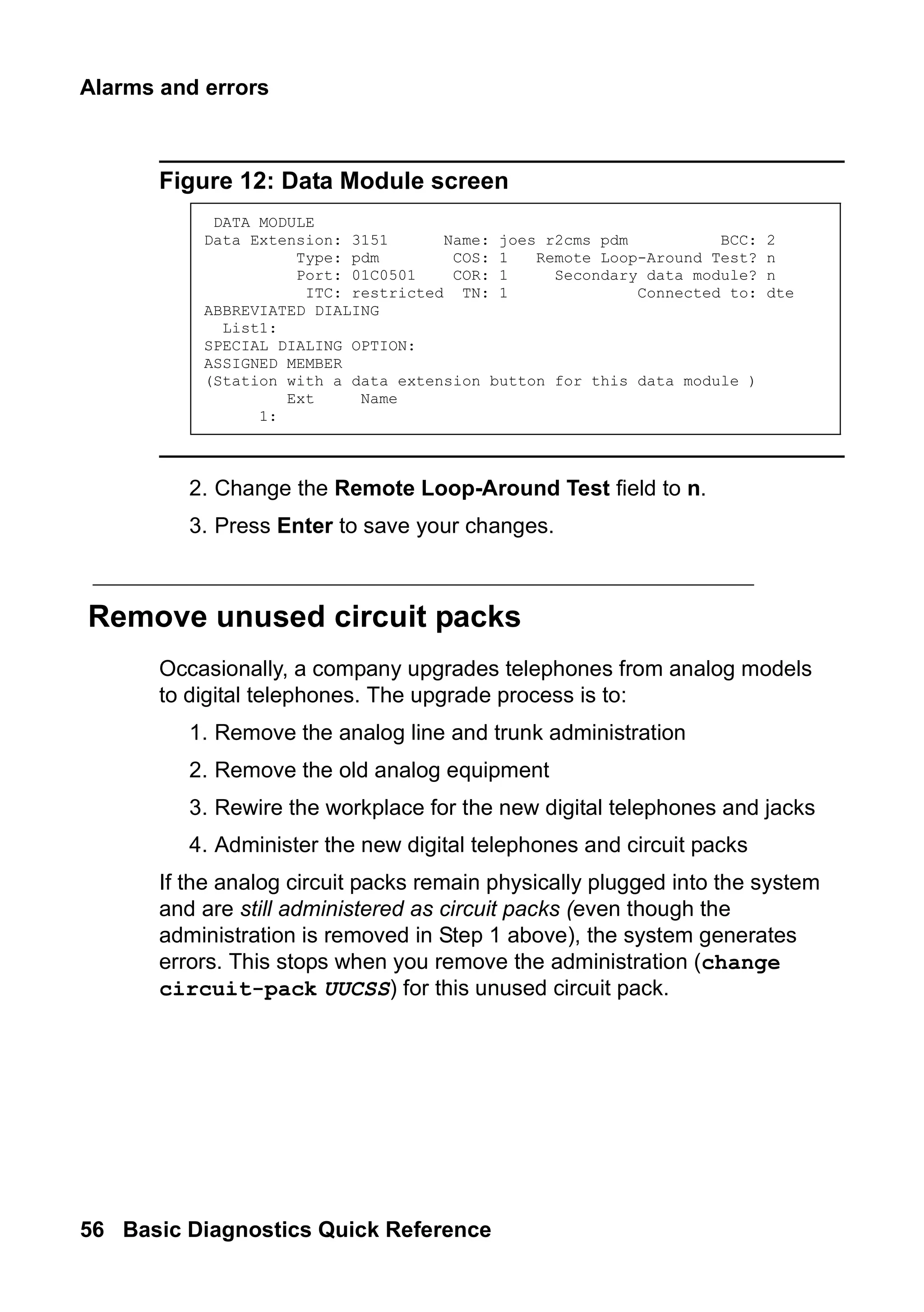
To turn off the maintenance test:
1. Type change data-module n, where n is the extension
number. Press Enter.
The system displays the Data Module screen (Figure 12: Data
Module screen on page 56).
56.
Alarms and errors
56Basic Diagnostics Quick Reference
Figure 12: Data Module screen
2. Change the Remote Loop-Around Test field to n.
3. Press Enter to save your changes.
Remove unused circuit packs
Occasionally, a company upgrades telephones from analog models
to digital telephones. The upgrade process is to:
1. Remove the analog line and trunk administration
2. Remove the old analog equipment
3. Rewire the workplace for the new digital telephones and jacks
4. Administer the new digital telephones and circuit packs
If the analog circuit packs remain physically plugged into the system
and are still administered as circuit packs (even though the
administration is removed in Step 1 above), the system generates
errors. This stops when you remove the administration (change
circuit-pack UUCSS) for this unused circuit pack.
DATA MODULE
Data Extension: 3151 Name: joes r2cms pdm BCC: 2
Type: pdm COS: 1 Remote Loop-Around Test? n
Port: 01C0501 COR: 1 Secondary data module? n
ITC: restricted TN: 1 Connected to: dte
ABBREVIATED DIALING
List1:
SPECIAL DIALING OPTION:
ASSIGNED MEMBER
(Station with a data extension button for this data module )
Ext Name
1:
57.
Preventing alarms anderrors
Issue 2 June 2005 57
alarms
/
errors
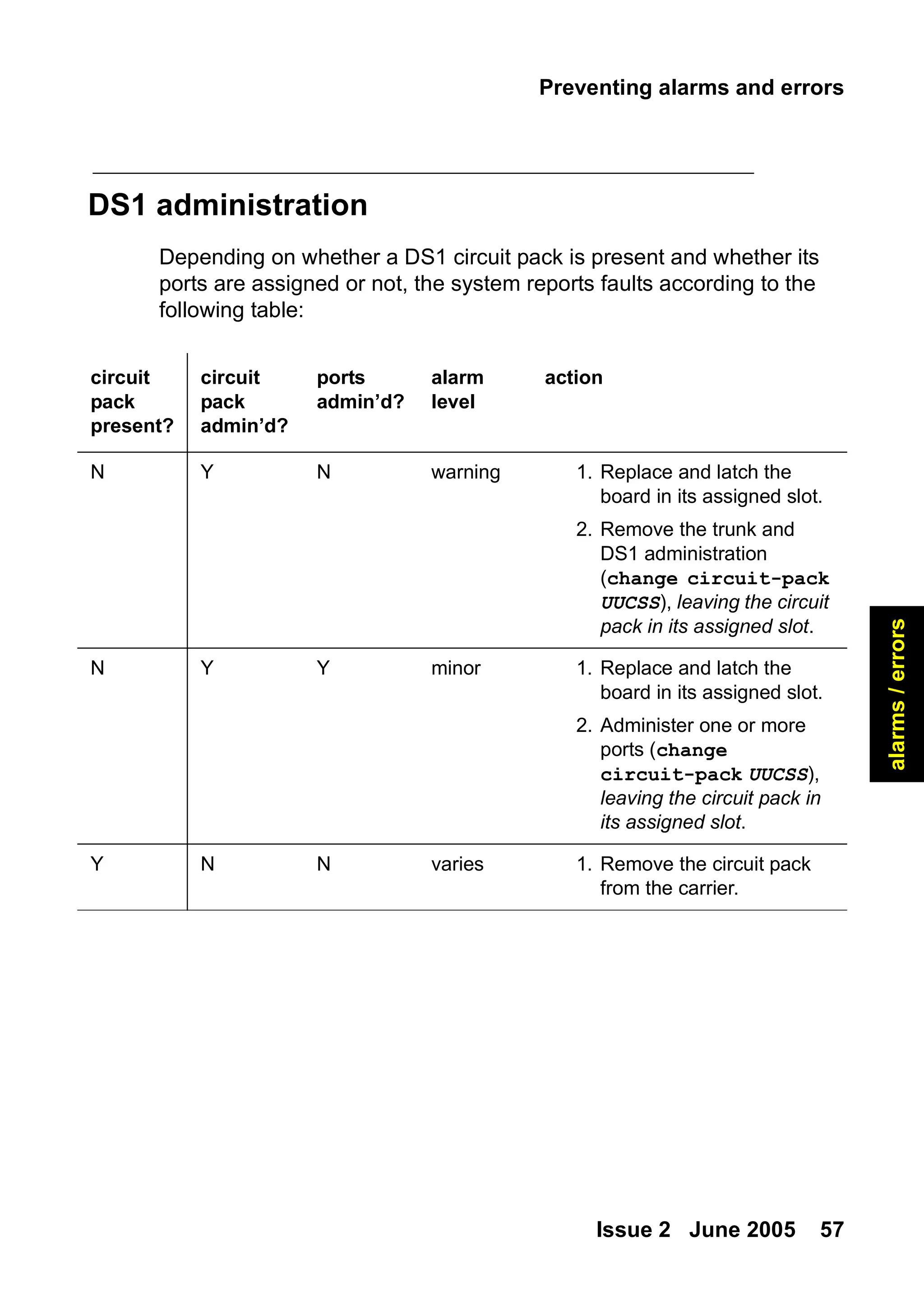
DS1 administration
Depending on whether a DS1 circuit pack is present and whether its
ports are assigned or not, the system reports faults according to the
following table:
circuit
pack
present?
circuit
pack
admin’d?
ports
admin’d?
alarm
level
action
N Y N warning 1. Replace and latch the
board in its assigned slot.
2. Remove the trunk and
DS1 administration
(change circuit-pack
UUCSS), leaving the circuit
pack in its assigned slot.
N Y Y minor 1. Replace and latch the
board in its assigned slot.
2. Administer one or more
ports (change
circuit-pack UUCSS),
leaving the circuit pack in
its assigned slot.
Y N N varies 1. Remove the circuit pack
from the carrier.
Troubleshooting
Issue 2 June2005 59
features
5: Using features to
troubleshoot
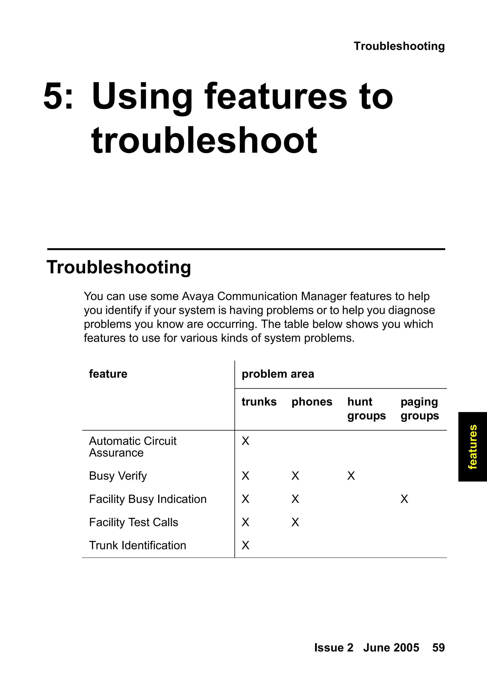
Troubleshooting
You can use some Avaya Communication Manager features to help
you identify if your system is having problems or to help you diagnose
problems you know are occurring. The table below shows you which
features to use for various kinds of system problems.
feature problem area
trunks phones hunt
groups
paging
groups
Automatic Circuit
Assurance
X
Busy Verify X X X
Facility Busy Indication X X X
Facility Test Calls X X
Trunk Identification X
60.
Using features totroubleshoot
60 Basic Diagnostics Quick Reference
Automatic Circuit Assurance
You can use Automatic Circuit Assurance (ACA) to help identify faulty
trunks. If activated, your system notifies you with a referral call when
it detects unusual trunk usage like very short or very long calls. It
needs to be turned on for each individual trunk group.
The referral call arrives on an idle call appearance. If you answer the
call, your display shows:
● that the call is an ACA call
● the trunk-group access code
● the trunk-group member number
● the reason for the call (short or long holding time)
To use ACA on a G3V2 or older system
1. Assign an ACA button to your telephone.
2. Press the ACA button to activate your telephone for referrals.
3. When you receive an ACA referral call, answer the call.
4. Record the information listed on your display to use for further
troubleshooting.
To use ACA on a G3V3 or newer system
1. Assign an ACA-Halt button to your telephone.
2. Leave the ACA-Halt button OFF to keep your telephone active
for referrals.
3. When you receive an ACA referral call, answer the call.
4. Record the information listed on your display to use for further
troubleshooting.
61.
Troubleshooting
Issue 2 June2005 61
features
Busy Verify
You can use Busy Verify to place test calls to check the busy
condition of trunks, telephones, or hunt groups. This test helps you
determine if the trunk, telephone, or hunt group is busy because of
heavy use or appears busy because of a problem.
To use Busy Verify, you should administer a Busy Verify button on
your telephone.
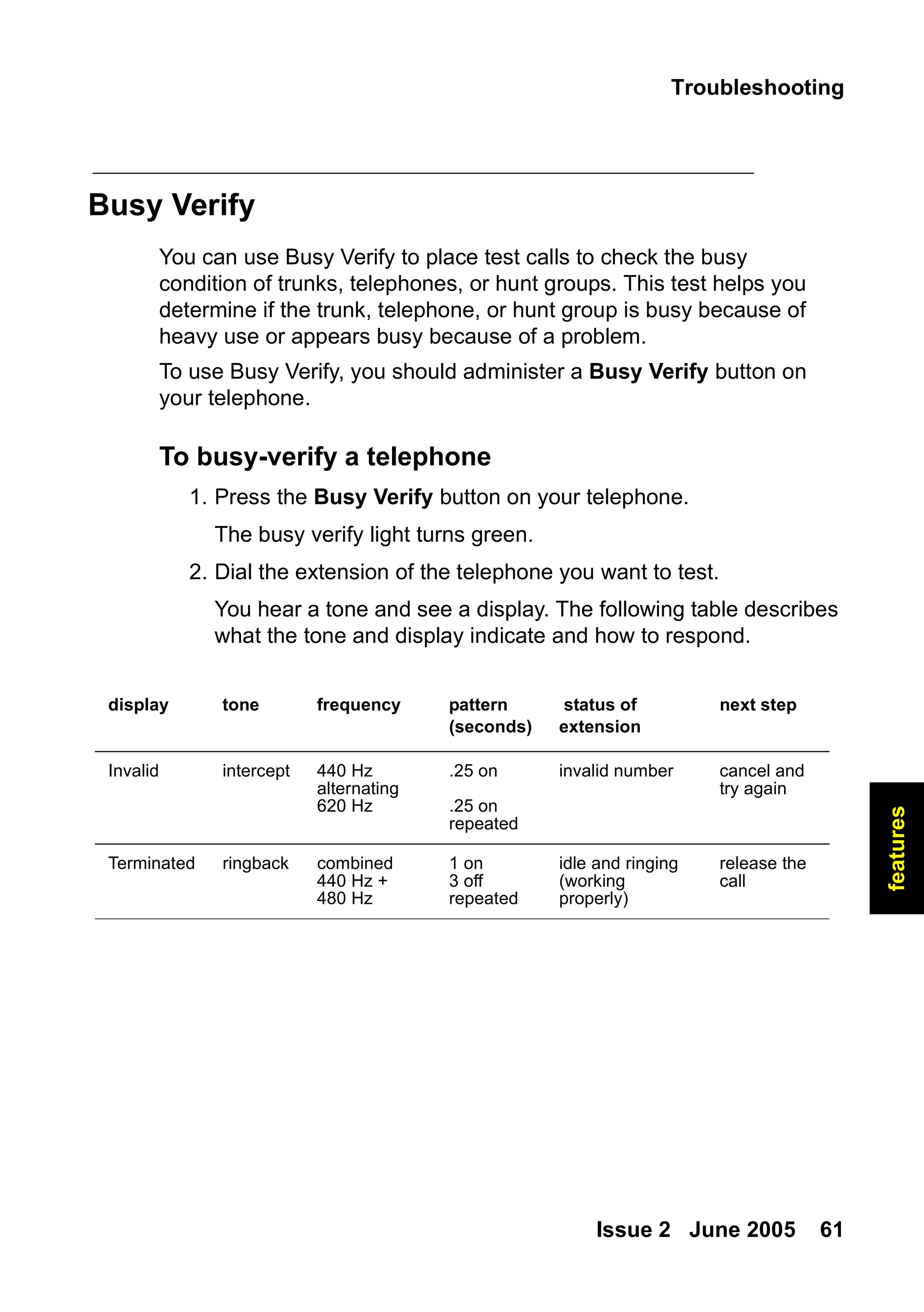
To busy-verify a telephone
1. Press the Busy Verify button on your telephone.
The busy verify light turns green.
2. Dial the extension of the telephone you want to test.
You hear a tone and see a display. The following table describes
what the tone and display indicate and how to respond.
display tone frequency pattern
(seconds)
status of
extension
next step
Invalid intercept 440 Hz
alternating
620 Hz
.25 on
.25 on
repeated
invalid number cancel and
try again
Terminated ringback combined
440 Hz +
480 Hz
1 on
3 off
repeated
idle and ringing
(working
properly)
release the
call
62.
Using features totroubleshoot
62 Basic Diagnostics Quick Reference
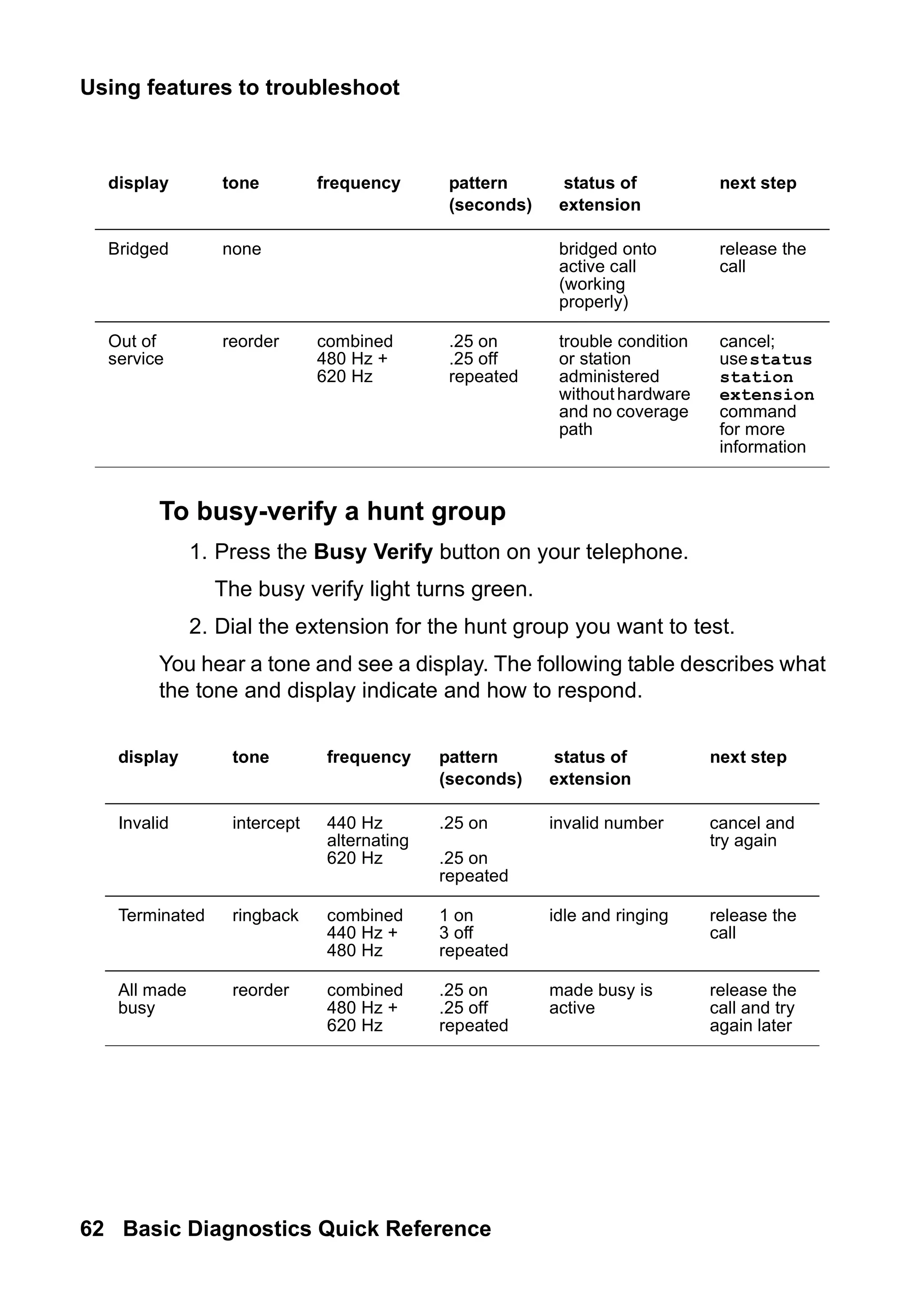
To busy-verify a hunt group
1. Press the Busy Verify button on your telephone.
The busy verify light turns green.
2. Dial the extension for the hunt group you want to test.
You hear a tone and see a display. The following table describes what
the tone and display indicate and how to respond.
Bridged none bridged onto
active call
(working
properly)
release the
call
Out of
service
reorder combined
480 Hz +
620 Hz
.25 on
.25 off
repeated
trouble condition
or station
administered
withouthardware
and no coverage
path
cancel;
usestatus
station
extension
command
for more
information
display tone frequency pattern
(seconds)
status of
extension
next step
display tone frequency pattern
(seconds)
status of
extension
next step
Invalid intercept 440 Hz
alternating
620 Hz
.25 on
.25 on
repeated
invalid number cancel and
try again
Terminated ringback combined
440 Hz +
480 Hz
1 on
3 off
repeated
idle and ringing release the
call
All made
busy
reorder combined
480 Hz +
620 Hz
.25 on
.25 off
repeated
made busy is
active
release the
call and try
again later
63.
Troubleshooting
Issue 2 June2005 63
features
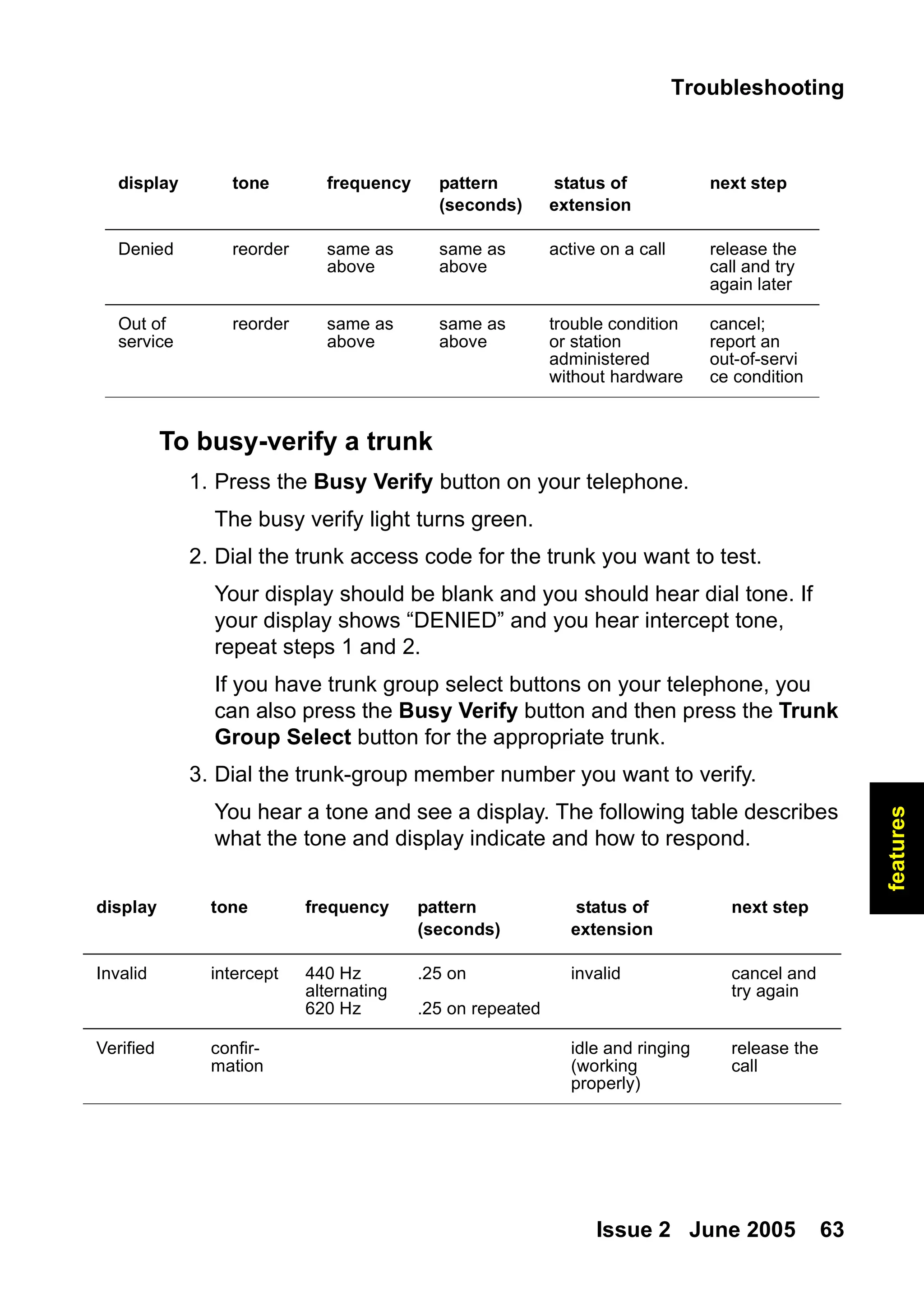
To busy-verify a trunk
1. Press the Busy Verify button on your telephone.
The busy verify light turns green.
2. Dial the trunk access code for the trunk you want to test.
Your display should be blank and you should hear dial tone. If
your display shows “DENIED” and you hear intercept tone,
repeat steps 1 and 2.
If you have trunk group select buttons on your telephone, you
can also press the Busy Verify button and then press the Trunk
Group Select button for the appropriate trunk.
3. Dial the trunk-group member number you want to verify.
You hear a tone and see a display. The following table describes
what the tone and display indicate and how to respond.
Denied reorder same as
above
same as
above
active on a call release the
call and try
again later
Out of
service
reorder same as
above
same as
above
trouble condition
or station
administered
without hardware
cancel;
report an
out-of-servi
ce condition
display tone frequency pattern
(seconds)
status of
extension
next step
display tone frequency pattern
(seconds)
status of
extension
next step
Invalid intercept 440 Hz
alternating
620 Hz
.25 on
.25 on repeated
invalid cancel and
try again
Verified confir-
mation
idle and ringing
(working
properly)
release the
call
64.
Using features totroubleshoot
64 Basic Diagnostics Quick Reference
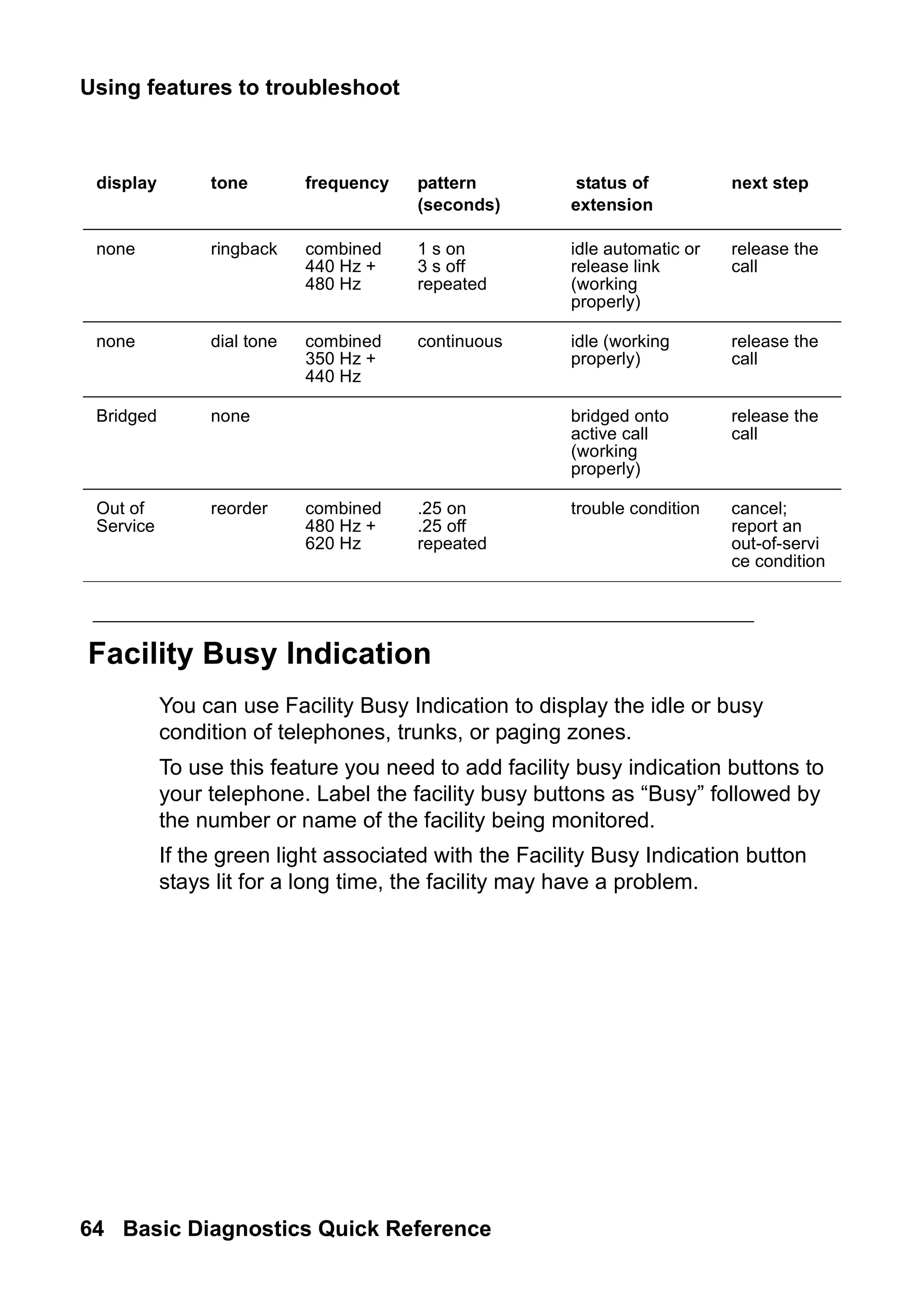
Facility Busy Indication
You can use Facility Busy Indication to display the idle or busy
condition of telephones, trunks, or paging zones.
To use this feature you need to add facility busy indication buttons to
your telephone. Label the facility busy buttons as “Busy” followed by
the number or name of the facility being monitored.
If the green light associated with the Facility Busy Indication button
stays lit for a long time, the facility may have a problem.
none ringback combined
440 Hz +
480 Hz
1 s on
3 s off
repeated
idle automatic or
release link
(working
properly)
release the
call
none dial tone combined
350 Hz +
440 Hz
continuous idle (working
properly)
release the
call
Bridged none bridged onto
active call
(working
properly)
release the
call
Out of
Service
reorder combined
480 Hz +
620 Hz
.25 on
.25 off
repeated
trouble condition cancel;
report an
out-of-servi
ce condition
display tone frequency pattern
(seconds)
status of
extension
next step
65.
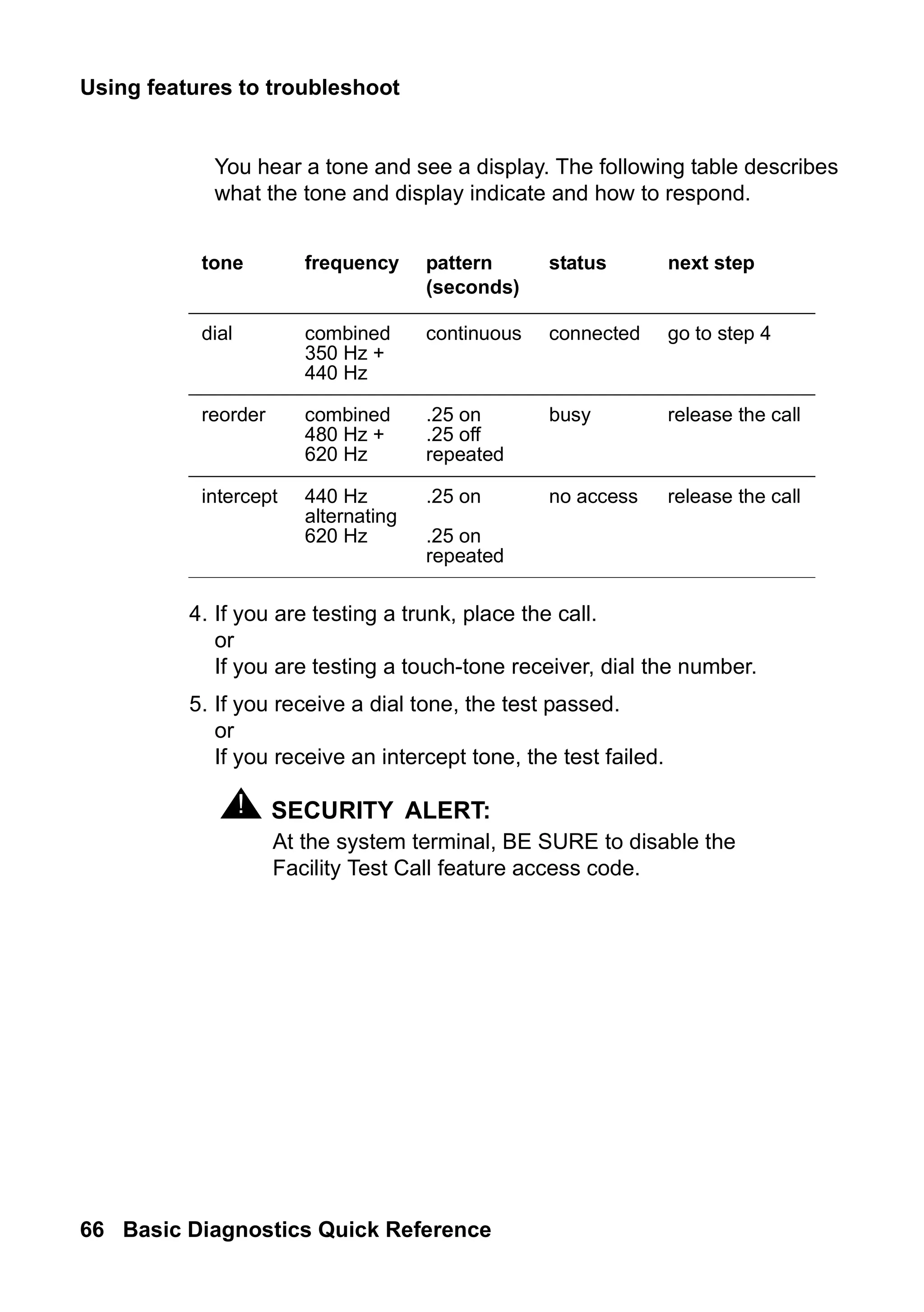
Troubleshooting
Issue 2 June2005 65
features
Facility Test Calls
You can use Facility Test Calls to place test calls to specific trunks or
telephones. Because this feature bypasses the regular system traffic,
it is very helpful in finding noisy lines and other problems. However,
this feature can be easily misused by outside parties. Disable this
feature when you are not using it.
! SECURITY ALERT:
SECURITY ALERT: Whenever you use this feature, enable the feature
access code only for the tests you want to make. Be
sure to immediately remove the access code when
you are through testing because leaving this feature
enabled can leave you open to security breaches.
To place a test call to a trunk or touch-tone telephone
1. At the system terminal, enable a feature access code for Facility
Test Call.
2. At your telephone, dial the feature access code for Facility Test
Call. Listen for dial tone.
3. Dial the 6- or 7-digit port address in UUCSSss format, where:
UU = cabinet number (01, 02, etc.)
C = carrier number (A=1, B=2, C=3, D=4, E=5)
SS = slot number (depends on system)
ss = port number (depends on circuit pack)
Note:
Note: If you have problems with this step, try dialing the port
address without the first zero in the cabinet number.
66.
Using features totroubleshoot
66 Basic Diagnostics Quick Reference
You hear a tone and see a display. The following table describes
what the tone and display indicate and how to respond.
4. If you are testing a trunk, place the call.
or
If you are testing a touch-tone receiver, dial the number.
5. If you receive a dial tone, the test passed.
or
If you receive an intercept tone, the test failed.
! SECURITY ALERT:
SECURITY ALERT: At the system terminal, BE SURE to disable the
Facility Test Call feature access code.
tone frequency pattern
(seconds)
status next step
dial combined
350 Hz +
440 Hz
continuous connected go to step 4
reorder combined
480 Hz +
620 Hz
.25 on
.25 off
repeated
busy release the call
intercept 440 Hz
alternating
620 Hz
.25 on
.25 on
repeated
no access release the call
67.
Troubleshooting
Issue 2 June2005 67
features
Trunk Identification
You can identify a faulty or noisy trunk with Trunk Identification. You
can use Trunk Identification:
● on an active call
● while accessing a trunk
To identify the specific trunk used on a call:
1. Press the Trunk ID button.
Trunk access code and trunk group member number appears on
the display.
If 2 trunks are used on the call, the identification of the last trunk
added to the call displays. If more than 2 trunks are on a call,
Trunk Identification is denied.
2. See if there are any on-board alarms against a trunk circuit pack.
If no, report the trunk problem to the appropriate vendor.
If yes, report the trunk problem and the identification information
to Avaya.
Solving Softphone problems
Issue2 June 2005 69
IP
&
H.323
6: Solving IP and
H.323 problems
This section describes some basic troubleshooting tips and tools that
may help you solve problems with IP (internet protocol) telephones,
Softphones, and IP and H.323 trunk issues.
In addition to using this section, you may want to refer to
Administration for Network Connectivity for Avaya Communication
Manager, 555-233-504, for basic IP administration.
Solving Softphone problems
This section discusses some common problems you or your users
may encounter while using IP Softphones (telecommuter or
RoadWarrior types).
Note:
Note: R1 and R2 IP Softphone and IP Agent, which use a dual
connect (two extensions) architecture, are no longer
supported. R3 and R4 IP Softphone and IP Agent, which
use a single connect (one extension) architecture, continue
to be supported. This applies to the RoadWarrior
configuration and the Native H.323 configuration for the IP
Softphone.
70.
Solving IP andH.323 problems
70 Basic Diagnostics Quick Reference
Users cannot login (register) with IP Softphone
The user’s password needs to be the same as the administered
station security code. So, the first thing to verify is whether or not the
user is using the correct password. If they are using the correct
password, then you should determine if the problem is with their PC.
To determine if the problem is related to the user’s PC, try to register
(login) this extension from another PC. If you can successfully
register, then the problem is within the user’s PC. If you cannot
register, then the extension may not be administered correctly or you
may have a network problem.
User is logged in, but cannot use Softphone for
calls
If you see the message “Telephony is not available” in the call status
area, then you may have COR to COR restrictions between the
IP Softphone and the actual hard telephone used to make calls.
If you do not have restrictions, then try logging off and back in again.
If that fails, reboot the PC that the Softphone is running on.
! WARNING:
WARNING: Some system platforms also run on a PC. If you
reboot a system PC that is running a D1, all calls will
be lost. In that case, you might want to wait until after
normal business hours to reboot the PC.
71.
Solving Softphone problems
Issue2 June 2005 71
IP
&
H.323
Cannot listen to messages with
INTUITY Message Manager
When a user is logged in to IP Softphone in the Roadwarrior
application, the Softphone has control of the PC sound card. Since
only one application can control the PC sound card at a time, the
sound card will not be available to Message Manager.
Users get message “Action cannot be completed”
The user may have a button on the IP Softphone that is not actually
administered on the Station screen for the extension. Or the user is
trying to dial a feature access code that is not administered in the
system.
User cannot conference or transfer
Both the conference and the transfer operations require at least two
lines. Make sure the user has more than one line available to place
calls. To determine if the user has more than one line appearance,
complete the following steps:
1. At the IP Softphone, select Number of Calls from the Options
menu.
2. Verify that the Minimum or Default number of lines to be
displayed is more than one.
72.
Solving IP andH.323 problems
72 Basic Diagnostics Quick Reference
Users cannot use Directory
In order to use the directory, users must have a Directory, Normal,
and Next button available.
Other tips
If your users get the message “Communication to the server has
been lost. You will be logged off by the server,” the only option is to
click OK. However, if the user is active on a call, they can finish the
call before they click OK.
Sound quality problems
Because of the myriad of networks and equipment involved in an IP
call, there are a lot of factors that may contribute to sound quality
problems. This section contains tips for how to determine the source
of the problem, and some things you can do that may help.
Isolating problems in the LAN
or the Communication Manager setup
There are a few easy things you can do to determine if a voice quality
problem is in the Communication Manager setup or in your LAN
or PC.
To check the PC sound quality, create and play back a sound file
using the PC sound recorder. If the sound quality is unacceptable, the
problem is somewhere in your headset or sound card.
73.
Sound quality problems
Issue2 June 2005 73
IP
&
H.323
To check sound quality over the LAN, shut down IP Softphone. Now
start up Net Meeting and initiate a call. This completely bypasses the
Communication Manager. Therefore, if you are still experiencing
sound quality problems, the source must be somewhere within the
LAN. If this resolves the sound quality problem, the issue is with the
Communication Manager setup.
Note:
Note: For more information on NetMeeting, see Microsoft’s Web
site at www.microsoft.com.
Running a mute test
The mute test can also help determine the source of a sound quality
problem. To run this test, set up an IP softphone test call between two
users who are experiencing voice quality problems. Have one user
mute their telephone and have the other user count aloud to 10. If the
sound quality improves, then the problem is in the sound card,
microphone, or headset of the muted telephone. If the sound quality
does not improve, try the test again, but this time mute the other
telephone.
Checking the PC volume control
Softphone has its own volume controls, but sometimes the volume
controls on the PC need to be adjusted. If the PC volume controls are
set too loud, it can cause sound quality to be distorted. If the PC
volume controls are set too low, it may be difficult to hear clearly. Try
adjusting the volume control on the PC to resolve the problem.
74.
Solving IP andH.323 problems
74 Basic Diagnostics Quick Reference
Checking for packet loss and jitter
Packet loss and jitter can cause a noisy connection that eventually
breaks up, creating gaps in the conversation and making speech
unintelligible. Use status station to check for station-side IP
problems, including problems with an IP telephone, and use status
trunk to check for trunk-side IP problems.
Each command generates snapshot jitter buffer size (ms) and packet
loss report for a particular station or trunk group member that shows:
● the number of packets that are lost or corrupted
● amount of jitter on the connection
In this instance, jitter is the variability in the amount of time (in
milliseconds) that packets are received over the network. When jitter
increases, the user experiences a noisy connection, delays, and a
general loss of quality, making speech unintelligible.
Note:
Note: If you issue a status station or status trunk
command for a non-IP station, or the connection is
hairpinned or shuffled, then the packet loss and jitter size
information does not appear. For more information, see the
Administration for Network Connectivity for Avaya
Communication Manager, 555-233-504.
Other possible causes
If a user is browsing the web while using softphone and they are
accessing web sites with large graphics, they may experience an
interruption in voice transmission.
75.
Basic troubleshooting tools
Issue2 June 2005 75
IP
&
H.323
Basic troubleshooting tools
This section describes some basic tools that you can use to
understand better what is going on in your network and with the IP
hardware and software.
Using ping
The ping command helps you to determine if endpoints on the
network are available to place or receive calls, and if nodes in the
network are active. You can specify which circuit pack you want to
ping.
For example, to ping from a C-LAN circuit pack at 01A011 to an
endpoint at 111.122.133.144, complete the following steps:
1. Type ping ip-address 111.122.133.144 board 01A011.
Use the IP address of the endpoint that you want to ping, and the
board location for the specific pack that you want to test.
You can also use the ping node-name to ping a node defined
on the Node Names screen.
2. Press Enter.
The system displays the Ping Results screen (Figure 13: Ping
Results screen on page 75).
Figure 13: Ping Results screen
3. Review the report to see if pinging the endpoints failed or if the
round-trip time was too long.
PING RESULTS
End-pt Node-name Port Port Type Result Time (ms) Error code
111.122.133.144 01A011 ETH-PT PASS 60
76.
Solving IP andH.323 problems
76 Basic Diagnostics Quick Reference
Using trace-route
The trace-route command helps you test the path that a call takes
from the PC endpoint, through the various nodes in a network.
Trace-route can help you see where in the network a problem may be
occurring.
For example, to determine the path from a C-LAN circuit pack at
01A011 to an endpoint at 111.122.133.144, complete the following
steps:
1. Type trace-route ip-address 111.122.133.144 board
01A011.
Use the IP address of the endpoint you want to reach and the
board location for the specific pack you want to test.
You can also use the trace-route node-name to test the
path to a node defined on the Node Names screen.
2. Press Enter.
The system displays the Trace Route Results screen
(Figure 14: Trace Route Results screen on page 76).
Figure 14: Trace Route Results screen
TRACE ROUTE RESULTS
Hop Time (ms) IP Address
0 Start Addr: 111.44.33.122
1 5, 6, 6 111.44.33.144
2 35, 36, 37 111.44.33.111
3 49, 51, 51 111.122.133.111
4 58, 58, 59 111.122.133.144
77.
Basic troubleshooting tools
Issue2 June 2005 77
IP
&
H.323
3. Verify that the last IP address on the report is the same as the IP
endpoint you specified in Step 1.
If the system was unable to follow the full path, it lists the last
address that it could successfully reach. This information may
help you narrow which part of the network is experiencing
problems.
Finding the IP address
In some cases, you will want to know the IP address of a PC so that
you can ping it or trace the route of a call to it. To determine the IP
address, complete the following steps:
1. At the PC, open a Command Prompt (DOS) window.
Typically you can access the command prompt by selecting Start
> Programs > Command Prompt.
2. At the Command prompt, type winntsystem32ipconfig
(Windows NT/2000) or winipcfg (Windows 95/98).
3. Record the IP address for the PC.
Verifying the IP Softphone registration
Sometimes you will need to know whether or not an IP Softphone is
registered. For example, to determine whether the Softphone at
extension 4455 is registered, complete the following steps:
1. Type status station 4455. Press Enter.
The system displays the General Status screen.
2. Look at the Registration Status field on the second page. If the
word “authenticated” appears, the Softphone is registered.
78.
Solving IP andH.323 problems
78 Basic Diagnostics Quick Reference
Verifying the trunk type
Sometimes you will need to know whether or not a trunk group is an
IP type endpoint. For example, to determine whether the trunk
member 01 of trunk group 40 is an IP endpoint, complete the
following steps:
1. Type status trunk 40/01. Press Enter.
The system displays the Trunk Status screen.
2. Verify that the Port field is T000nn.
If this field displays a standard port address (for example,
01A0210), then the trunk is not an IP endpoint.
When all else fails
Reboot the PC. When you are experiencing unexpected behavior that
you cannot easily fix, you may want to close all your applications and
reboot the machine.
! WARNING:
WARNING: Some system platforms also run on a PC. If you
reboot a system PC that is running a D1, all calls will
be lost. In that case, you might want to wait until after
normal business hours to reboot the PC.
79.
Preparing to contactAvaya
Issue 2 June 2005 79
contacting
7: Contacting Avaya
This section describes what information you should have handy when
you need to contact the Avaya Technical Service Center (TSC). This
section also provides a list of telephone numbers you can call when
you have a problem with your system.
Preparing to contact Avaya
Do you need to call Avaya for additional information or help in solving
a problem? If you do, please have the following information handy.
This helps the person taking your call.
● your name and number (in case we need to call you back)
● your installation location number (also called your IL)
___________________________________
(Write your IL number here for easy reference)
● your company’s main telephone number
● the type of your system
● the number of trunks on your system
● the number of stations on your system
Also, use the information in this book to determine the possible
source of your problem. It always helps to keep a log of the steps you
took and the information you gathered while performing your
diagnosis. This information is extremely helpful when you partner with
an Avaya representative in solving your system problems.
80.
Contacting Avaya
80 BasicDiagnostics Quick Reference
Remember, if the problem is with equipment or service outside of
your own equipment, you need to call your vendor or service provider.
If you determine that the problem is with your own equipment, such
as on your own stations, system, or trunks, give Avaya a call.
If you are not sure where the problem is located, double-check your
system information. Refer to Problem solving strategies on page 25
for more information.
Be ready to talk about:
● the problem you want to solve
● if the problem is with a new component or feature
● if something that used to work now does not work
● any numbers involved with the problem (for example,
extensions or telephone numbers, trunk group numbers,
telephone types, or report types)
● the contents of any recorded messages received
● error messages from the system
● type of ringback tones received on telephones
● the names and numbers of your vendors
● any other pertinent information
81.
Contacting Avaya
Issue 2June 2005 81
contacting
Contacting Avaya
The following table lists additional services available to you. If you are
outside of the 1 800 calling area, contact your local Avaya
representative.
Technical Service Center for Large-Systems
Customers and Toll Fraud Crisis Intervention
(for help with repairs)
1 800 242 2121
Communication Manager Helpline (for
administration and software problems,
including vectors, how features work,
administration, and interactions)
1 800 225 7585