From Event to Action: Accelerate Your Decision Making with Real-Time Automation
5g_norma_d4-2.pdf
1. Project: H2020-ICT-2014-2 5G NORMA
Project Name:
5G Novel Radio Multiservice adaptive network Architecture (5G NORMA)
Deliverable D4.2
RAN architecture components –
final report
Date of delivery: 30/06/2017 Version: 1.0
Start date of Project: 01/07/2015 Duration: 30 months
2. Document properties:
Document Number: H2020-ICT-2014-2 5G NORMA/D4.2
Document Title: RAN architecture components – final report
Editor(s): Mark Doll
Authors: Hajo Bakker, Mark Doll, Diomidis Michalopoulos, Vinh
Van Phan, Peter Rost, Peter Schneider (Nokia);
Vincenzo Sciancalepore (NEC); Jorge Rivas (Atos);
Alessandro Colazzo (Azcom); Sina Khatibi, Kunjan Shah
(Nomor); Vasilis Friderikos, Oliver Holland (King’s
College London); Bin Han, Shreya Tayade (TU
Kaiserslautern); Albert Banchs, Maria Cristina Márquez
Colás (Universidad Carlos III de Madrid)
Contractual Date of Delivery: 30/06/2017
Dissemination level: Public
Status: Final
Version: 1.0
File Name: 5G NORMA D4.2
Revision History
Revision Date Issued by Description
1.0 21.07.2017 5G NORMA WP4 Final version
Abstract
The main goal of 5G NORMA is to propose a multi-tenant multi-service mobile network architecture
that adapts the use of the mobile network resources to the service requirements, the variations of the
traffic demands over time and location, and the network topology, individually and concurrently for
multiple tenants that share the infrastructure. This is the final deliverable of WP4 containing the
findings of WP4 after the third 5G NORMA design iteration. Three options for RAN slicing, namely
slice-specific RAN, splice-specific radio bearer and slice-aware RAN, are presented. Standardization
relevance and potential of 5G NORMA innovations are discussed and a comparison with respective
aspects of the 3GPP next generation architecture is made. Then, we show how the functionally
decomposed c/d-layer can be adapted to specific services through suitable function selection and
placement as well as how to use the functionally decomposed c/d-layer to realize a multi-service radio
access. The c/d-layer function blocks are characterized and categorised into data layer, distributed and
centralized control, respectively. Besides these architectural aspects, we introduce specific solutions
for multi-tenancy RRM and admission control, for multi-connectivity support to increase reliability,
integrate mm-wave and realize virtual cells, for signalling optimizations of mMTC and finally discuss
the usefulness of geolocation DBs for mobile networks. Security considerations for both architecture
design and specific solutions complete the 5G NORMA view on flexible RAN design.
Keywords
5G, mobile radio network architecture, RAN architecture components, functional decomposition,
multi-tenancy, multi-service, multi-connectivity, NFV, network slicing, RAN slicing, physical network
functions, SDMC
3. 5G NORMA Deliverable D4.2
Dissemination level: Public Page 3 / 158
Table of Contents
1 Introduction......................................................................................................................... 14
1.1 Scientific highlights..................................................................................................... 14
1.2 Outline and relation to other work packages ............................................................... 15
2 Flexible network design...................................................................................................... 17
2.1 RAN Slicing................................................................................................................. 17
2.1.1 Slice-specific RAN (Option 1) ............................................................................... 19
2.1.2 Slice-specific radio bearer (Option 2)..................................................................... 20
2.1.3 Slice-aware shared RAN (Option 3)....................................................................... 22
2.1.4 Exemplary use of RAN Slicing .............................................................................. 23
2.2 Standardization relevance and potential ...................................................................... 24
3 Use of functional decomposition for service adaptation.................................................. 29
3.1 Function selection and placement................................................................................ 29
3.2 Multi-service radio access ........................................................................................... 32
3.3 Security considerations................................................................................................ 34
4 Control and data layer ....................................................................................................... 36
4.1 Centralized control....................................................................................................... 36
4.2 Distributed control....................................................................................................... 40
4.3 Data layer..................................................................................................................... 41
4.4 Security considerations................................................................................................ 43
4.4.1 Securing inter-domain interfaces............................................................................ 43
4.4.2 Securing intra-domain interfaces............................................................................ 45
5 Multi-tenancy...................................................................................................................... 47
5.1 Multi-tenancy aspects of RRM.................................................................................... 47
5.1.1 Multi-tenancy radio-resource management ............................................................ 47
5.1.2 Reinforcement learning for network slice resource management........................... 49
5.2 Multi-tenancy in multi-RAT environments ................................................................. 54
5.2.1 Admission control................................................................................................... 54
5.2.2 Dynamic resource sharing ...................................................................................... 56
5.3 Security considerations................................................................................................ 58
5.3.1 Isolation between multiple tenants ......................................................................... 58
5.3.2 Trust relationships .................................................................................................. 59
6 Multi-technology architecture in HetNets ........................................................................ 60
6.1 Multi-connectivity algorithm....................................................................................... 60
6.1.1 The Inter-RAT Link Controller .............................................................................. 60
6.1.2 Slice specific constraints......................................................................................... 60
6.1.3 Proposed algorithm................................................................................................. 62
6.2 Clustering of mm-wave access points controlled by a 5G low band coverage layer... 63
6.3 Virtual cells and multi-cell coordination ..................................................................... 65
6.3.1 Novel virtual cell algorithm.................................................................................... 65
6.3.2 Forming virtual cell using Q-learning .................................................................... 69
6.3.3 Implementation of virtual cells in Demo 1............................................................. 71
6.4 User-centric connection area ....................................................................................... 71
6.5 Mobile edge computing ............................................................................................... 75
6.6 Massive machine-type communication RAN congestion control................................ 77
6.7 Geolocation database................................................................................................... 81
7 Conclusions.......................................................................................................................... 83
8 Annex A: Why no virtualized connectivity on the air interface? ................................... 85
4. 5G NORMA Deliverable D4.2
Dissemination level: Public Page 4 / 158
9 Annex B: List of function blocks ....................................................................................... 86
9.1 Data layer..................................................................................................................... 86
9.2 Distributed control....................................................................................................... 86
9.3 Centralized control....................................................................................................... 87
10 References............................................................................................................................ 89
11 Multi-tenancy in multi-RAT environments...................................................................... 94
11.1 Admission control........................................................................................................ 94
11.2 Dynamic resource sharing ........................................................................................... 95
12 Inter-slice resource sharing ............................................................................................... 98
12.1 Motivation and problem statement .............................................................................. 98
12.2 Related work................................................................................................................ 99
12.3 A mathematical programming formulation approach.................................................. 99
12.4 Evaluation.................................................................................................................. 101
12.5 Concluding remarks................................................................................................... 103
12.6 References.................................................................................................................. 103
13 Multiple connectivity at the different layers .................................................................. 105
13.1 Motivation and problem statement ............................................................................ 105
13.2 Architecture and process............................................................................................ 105
14 Data-layer and control-layer design for multi-connectivity.......................................... 108
14.1 Motivation and problem statement ............................................................................ 108
14.2 Related work.............................................................................................................. 109
14.3 Architectural approaches ........................................................................................... 110
14.4 Throughput evaluation of multi-connectivity............................................................ 111
14.5 References.................................................................................................................. 112
15 Architectural approaches for multi-connectivity of mm-wave APs and 5G low band
........................................................................................................................................ 113
15.1 Motivation and problem statement ............................................................................ 113
15.2 Major results.............................................................................................................. 113
15.3 Architectural approaches for provisioning of 5G-mmAPs ........................................ 113
15.4 Evaluation.................................................................................................................. 116
15.5 Security considerations.............................................................................................. 118
15.6 References.................................................................................................................. 118
16 Virtual cells and multi-cell coordination ........................................................................ 119
16.1 Security...................................................................................................................... 119
16.2 Numeric results.......................................................................................................... 119
16.3 The implementation of the Virtual Cell in Demo 1 ................................................... 121
16.4 References.................................................................................................................. 123
17 Flexible 5G service-flow (SF) with in-SF QoS differentiation and multi-connectivity
........................................................................................................................................ 124
17.1 PDCP multiplexing of SFs from different network slices ......................................... 124
17.2 Coordinated dynamic scheduling and semi-persistent scheduling based allocations
................................................................................................................................... 129
17.3 References.................................................................................................................. 132
18 User-centric connection area ........................................................................................... 133
18.1 Motivation and problem statement ............................................................................ 133
18.2 Major results.............................................................................................................. 133
18.3 Related work.............................................................................................................. 134
18.4 UCA concept ............................................................................................................. 134
18.5 Simulation framework ............................................................................................... 135
18.6 Simulation results ...................................................................................................... 137
5. 5G NORMA Deliverable D4.2
Dissemination level: Public Page 5 / 158
18.7 Security considerations.............................................................................................. 140
18.8 References.................................................................................................................. 140
19 Massive machine-type communication RAN congestion control ................................. 142
19.1 Impact analysis of D2D link exception...................................................................... 142
19.2 Enhanced grouping processes.................................................................................... 142
19.3 Enhanced transmission frame structure ..................................................................... 145
19.4 Geolocation database integration............................................................................... 146
19.5 Security considerations.............................................................................................. 147
19.6 Summary.................................................................................................................... 148
20 Geolocation databases, use of geolocation information and associated opportunities
........................................................................................................................................ 149
20.1 Motivation and problem statement ............................................................................ 149
20.2 Major results.............................................................................................................. 150
20.3 Related work.............................................................................................................. 152
20.4 Signalling procedures ................................................................................................ 153
20.5 Security considerations.............................................................................................. 157
20.6 References.................................................................................................................. 157
6. 5G NORMA Deliverable D4.2
Dissemination level: Public Page 6 / 158
List of Figures
Figure 2-1: Three RAN slicing options....................................................................................... 17
Figure 2-2: Functional control and data layer architecture, RAN slicing Option 1 (slice-specific
RAN)........................................................................................................................................... 19
Figure 2-3: Functional control and data layer architecture, RAN slicing Option 2 (slice-specific
radio bearer) (function types)...................................................................................................... 20
Figure 2-4: Integration of RAN slicing Option 2 and multi-connectivity based on MAC and PDCP
layer, respectively ....................................................................................................................... 21
Figure 2-5: Functional control and data layer architecture, RAN slicing Option 3 (shared RAN)
..................................................................................................................................................... 22
Figure 2-6: Exemplary deployment using RAN slicing in the context of an industrial campus
deployment.................................................................................................................................. 23
Figure 2-7: Overall architecture of 3GPP 5G network (Figure 4.1-1 of TS 38.300) .................. 24
Figure 2-8: Overview of functional split between 3GPP NG-RAN and 5GC (Figure 4.2-1 of TS
38.300) ........................................................................................................................................ 25
Figure 2-9: The gNB architecture with CU and DUs (Figure 11.1.3.8-1 of TR 38.801)............ 26
Figure 2-10: Functional split options between CU and DU (Figure 11.1.1-1 of TR 38.801) ..... 26
Figure 3-1: Function selection and placement (RAN slicing Option 2)...................................... 29
Figure 3-2: Multi-service vs. multi-tenancy and inter-tenant multi-connectivity vs (single tenant)
multi-connectivity ....................................................................................................................... 32
Figure 3-3: Example 5G New Radio multi-service RAT for RAN slicing Option 2.................. 33
Figure 4-1: 5G NORMA SDMC interfaces ................................................................................ 36
Figure 4-2: Abstraction layer turning non-SDN devices into SDN-controllable devices ........... 39
Figure 5-1: Reinforcement learning for slice admission control................................................. 49
Figure 5-2: Network slice admission control .............................................................................. 50
Figure 5-3: Pseudocode of the admission control algorithm....................................................... 52
Figure 5-4: Revenue vs 𝜌i/𝜌e ....................................................................................................... 56
Figure 5-5: Utility gains for different approaches as a function of network size........................ 58
Figure 6-1: Slice specific requirements and UE mapping........................................................... 60
Figure 6-2: Data duplication mode (left) and data split mode (right) ......................................... 61
Figure 6-3: Flow diagram of the proposed algorithm ................................................................. 62
Figure 6-4: Deployment of a UE specific multi-connectivity cluster of mmAPs on a 5G-LB
coverage layer ............................................................................................................................. 64
Figure 6-5: Activity Management within MC-Cluster, triggering of data transmission with flags
..................................................................................................................................................... 65
Figure 6-6: An example of the virtual cell concept (based on [CSS+16]).................................. 65
Figure 6-7: The network throughput increases as a function of the cell edge threshold (Scenario
A) ................................................................................................................................................ 68
Figure 6-8: The total network throughput and the three phases of the Q-learning. .................... 70
7. 5G NORMA Deliverable D4.2
Dissemination level: Public Page 7 / 158
Figure 6-9: The key elements of Demo 1 of WP6. ..................................................................... 71
Figure 6-10: Signalling messages towards the core based on 4G LTE....................................... 72
Figure 6-11: Reduction of signalling messages towards the core with the NORMA UCA concept
..................................................................................................................................................... 73
Figure 6-12: Gain over LTE for different RRC timer values and different UE speeds .............. 74
Figure 6-13: Gain over LTE for different paging are sizes......................................................... 74
Figure 6-14: Mobile Edge Computing platform supporting Slice QoS Monitoring ................... 75
Figure 6-15: Message sequence chart of MEC slice QoS monitoring/enforcement ................... 76
Figure 6-16: Different congestions and their sources in LTE-A networks ................................. 77
Figure 6-17: Comparing the performances of different RAN congestion controlling methods.. 78
Figure 6-18: The RAN topology in D2D-based grouped RA ..................................................... 78
Figure 6-19: Collision densities with respect to RACH resource dedication in a 2-DC-case
(DC1+DC2), numerical results obtained from 500 iterations of Monte-Carlo test..................... 80
Figure 6-20: Performances of different allocation methods, when DC1 is required to have an
average collision rate of 0.02 ...................................................................................................... 81
Figure 11-1. The distribution of the revenues obtained by random smart policies compared to the
proposed algorithms.................................................................................................................... 94
Figure 11-2. Revenue in perturbed scenario, 𝜌i /𝜌e = 5............................................................... 95
Figure 11-3: Normalised utility gain GW as a function of the maximum allowed number of
handovers m ................................................................................................................................ 95
Figure 11-4: Computational complexity of GLLG and SoA algorithms .................................... 96
Figure 11-5: Capacity saving ...................................................................................................... 96
Figure 11-6: Improvement on the user throughput ..................................................................... 97
Figure 12-1: Comparison between loose and tight coupling using a toy example scenario ....... 99
Figure 12-2: Aggregate rate vs. number of user........................................................................ 102
Figure 12-3: CDF of throughput per user.................................................................................. 102
Figure 13-1: C/d-layer architecture for multi-connectivity support in a multi RAT environment
................................................................................................................................................... 106
Figure 13-2: Message sequence chart for the inter-RAT link selection process....................... 107
Figure 14-1 The LTE RAN Architecture .................................................................................. 108
Figure 14-2 The 5G RAN Architecture considered in [5GN-D41] vs the existing LTE RAN
Architecture............................................................................................................................... 109
Figure 14-3 Transport connectivity options to small cells [NGMN-SBH] ............................... 110
Figure 14-4: The small-cell aggregation and centralized scenario architectural approach ....... 110
Figure 14-5: Throughput performance (at application layer) of approach 1............................. 112
Figure 14-6: Throughput performance (at application layer) of approach 2............................. 112
Figure 15-1: PDCP based MC with two variants for location of RRC protocol stack.............. 114
Figure 15-2: Architecture approach -2: split in PDCP_H and PDCP_L and related protocol stack
................................................................................................................................................... 114
Figure 15-3: Architecture approach-3: MAC based MC and related protocol stack................. 115
8. 5G NORMA Deliverable D4.2
Dissemination level: Public Page 8 / 158
Figure 15-4: Signalling messages flow between the node and the UE for approach-1a........... 116
Figure 15-5: Comparison of number of messages between different approaches..................... 118
Figure 16-1: The network throughput increases as a function of the cell edge threshold (Scenario
B)............................................................................................................................................... 119
Figure 16-2: The network throughput increases as a function of the cell edge threshold (Scenario
C)............................................................................................................................................... 120
Figure 16-3: The throughput of the cells in download direction............................................... 120
Figure 16-4: The throughput of the cells in download direction............................................... 121
Figure 16-5: Network reconfiguration into edge-cloud ............................................................ 122
Figure 16-6: Software demo with Edge-Cloud Configuration.................................................. 122
Figure 16-7: The beam coordination method............................................................................ 123
Figure 17-1: PDCP structure for PDCP multiplexing of SFs from different NSIs into one RB125
Figure 17-2: PDCP multiplexing of SFs from different NSIs into one RB............................... 125
Figure 17-3: Adding a NSI-SF into a multiplexed RB.............................................................. 127
Figure 17-4: Illustration of SN mapping inquiry procedure of PDCP ...................................... 127
Figure 17-5: Possible extension to cover NSI specific c-layer RRC, referred to as RRC_Slice128
Figure 17-6: TB formed based on the coordination between SPS and dynamic scheduling..... 130
Figure 17-7: Coordinated dynamic scheduling and SPS resource allocations.......................... 131
Figure 18-1: (a) Assignment and (b) update of UCA for a UE traversing the path shown by the
dashed line................................................................................................................................. 134
Figure 18-2: Saving of signalling messages towards the core with UCA compared to 4G LTE
................................................................................................................................................... 135
Figure 18-3: Idle/active modelling for simulation study based on SDP arrivals and UE mobility
................................................................................................................................................... 136
Figure 18-4: Definition of a UCA based on applying a window size to RSRP based UE
measurements............................................................................................................................ 136
Figure 18-5: UCA size and UCA updates with respect to UCA window size.......................... 137
Figure 18-6: Gain over LTE for different UE speeds with linear mobility............................... 138
Figure 18-7: Gain over LTE for different UE speeds and different mobility schemes............. 138
Figure 18-8: Gain over LTE for different packet inter-arrival times ........................................ 139
Figure 18-9: Gain over LTE for different RRC timer values and different UE speeds ............ 139
Figure 18-10: Gain over LTE for different paging are sizes..................................................... 140
Figure 19-1: The simulated impact of D2D link failure reports through extra RA processes... 142
Figure 19-2: The global group updating process....................................................................... 143
Figure 19-3: The group leaving process, triggered by detaching events................................... 143
Figure 19-4: The group leaving process, triggered by a GM losing D2D link but holding macro-
cell link...................................................................................................................................... 144
Figure 19-5: The group leaving process, triggered by a GM losing D2D and macro-cell links144
Figure 19-6: The group leaving process, triggered by handover events ................................... 145
9. 5G NORMA Deliverable D4.2
Dissemination level: Public Page 9 / 158
Figure 19-7: Frame structure of the grouped mMTC transmission based on D2D; the terms R/R,
UDT, A/C and DDT denote request/report, uplink data, acknowledgment/command, respectively
................................................................................................................................................... 145
Figure 19-8: GDB signalling (generic case).............................................................................. 147
Figure 20-1: Virtualized edge network slices achieving a more direct path compared with (fixed)
network elements in a Tactile Internet remote surgical operation example.............................. 149
Figure 20-2: Map of channel availability for a Class 3 white space device, for a large area of
England, for a 30m height above ground level transmitter, ≥30 dBm allowed power.............. 150
Figure 20-3: CCDFs of channel availability for different classes of white space device, for a large
area of England, for a 30 m height above ground level transmitter,≥30 dBm allowed power
scenario ..................................................................................................................................... 151
Figure 20-4: Example of latency CDFs for optimised (using the GDB) and non-optimised
Network Function placement. ................................................................................................... 152
Figure 20-5: Signalling—resource management (generalisation)............................................. 154
Figure 20-6: Signalling—rendezvous ....................................................................................... 155
Figure 20-7: Signalling—indirect access.................................................................................. 156
Figure 20-8: Signalling—Link to mMTC congestion control, MAC structuring ..................... 156
Figure 20-9: Signalling—Link to mMTC congestion control reflected in GDB signalling (partial)
................................................................................................................................................... 157
10. 5G NORMA Deliverable D4.2
Dissemination level: Public Page 10 / 158
List of Tables
Table 2-1: 5G NORMA innovations vs. 3GPP 5G, grouped according to the 5 key innovations
..................................................................................................................................................... 27
Table 4-1: Subset of parameters obtained for eMBMS Control.................................................. 38
Table 5-1: Traffic Class Requirements (similar QCI from [23.203]) ......................................... 49
Table 6-1: Virtual cell scenario configurations........................................................................... 67
Table 6-2: Process of MEC triggering MAC Scheduling to adapt scheduling ........................... 76
Table 6-3: Simulation specification.......................................................................................... 80
Table 6-4: Results in simulations under different DC combinations .......................................... 80
Table 12-1: Simulation parameters used for numerical investigations ..................................... 101
Table 18-1: Simulation parameter for UCA performance assessment...................................... 137
Table 20-1: Statistical results on number of allowed channels................................................. 151
Table 20-2: Scenarios (MBD: Mobile Broadband Downlink; IBP/MBU: Internal Broadband
Provisioning/Mobile Broadband Uplink).................................................................................. 151
11. 5G NORMA Deliverable D4.2
Dissemination level: Public Page 11 / 158
List of Acronyms and Abbreviations
3GPP 3rd Generation Partnership Project
5GC 5G Core
A/D Analog-to-Digital Converter
ABSF Almost-Blank Sub-Frame
ACK Acknowledgement
AI Air Interface
AMCC Activity Management within a Multi-
Connectivity cluster
AMF Access and Mobility Management Function
AMMC Activity Management within a Multi-
Connectivity cluster
ANDSF Access Network Discovery and Selection
Function
AP Access Point
API Application Programming Interface
ARP Allocation and Retention Priority
ARQ Automatic Repeat Request
AS Access Stratum
ATA Autonomous Timing Advance
BCCH Broadcast Control Channel
CA Carrier Aggregation
CAMADM Context-Aware Multiple Attribute Decision
Making
CAPEX Capital Expenditure
CBRS Citizens Broadband Radio Service
CCMCC Coordinated and Cooperative Multi-
Connectivity Cluster
CD Confidential Degree
CH Channel
CID Context Identification
CLI Command Line Interface
CN Core Network
CoMP Coordinated Multipoint Transmission and
Reception
CP Control Plane
CPC Cognitive Pilot Channel
CPRI Common Public Radio Interface
CQI Channel Quality Indication
CRC Cyclic Redundancy Check
CRE Cell Range Expansion
CRS Common Reference Signal
CRS Cell-specific Reference Signal
CSI Channel State Information
CSI-RS Channel State Information Reference Signal
D/A Digital-to-Analog Converter
D2D Device-to-Device
DC Device Class
DCCH Dedicated Control Channel
DCN Data Communication Network
DG Distributed Greedy
DL Downlink
DM-RS Demodulation Reference Signal
DPF Direct Provisioning Function
DRB Data Radio Bearer
DRX Discontinuous Reception
DS Dynamic Scheduling
E2E End-to-End
EC European Commission
eDECOR Enhancements of Dedicated Core Networks
eIMTA Enhanced Interference Mitigation and Traffic
Adaptation
eMBMS Evolved Multimedia Broadcast Multicast
Services
eMBSFN Evolved Multimedia Broadcast Single
Frequency network
EPC Evolved Packet Core
EPS Evolved Packet System
ETSI European Telecommunication Standard
Institute
EU European Union
E-UTRA Evolved Universal Terrestrial Radio Access
E-UTRAN Evolved Universal Terrestrial Radio Access
Network
FCC Federal Communications Commission
FDD Frequency Division Duplexing
FE Function Element
FEC Forward Error Correction
FFT Fast Fourier Transform
ForCES Forwarding and Control Element Separation
FPTAS Fully Polynomial Time Approximation
Schemes
GBR Guaranteed Bit Rate
GC Group Coordinator
GDB Geolocation Database
GLLG Greedy Local Largest Gain
GM Group Member
gNB Next Generation Node B
GTP GPRS Tunnelling Protocol
GWCN Gateway Core Network
H2020 Horizon 2020
HARQ Hybrid Automatic Repeat Request
HetNet Heterogeneous Network
HO Handover
HSPA High Speed Packet Access
HTC Human-Type Communication
HW Hardware
IAT Inter-Arrival Time
ICIC Inter-Cell Interference Cancelation
ICT Information and Communication
Technologies
IETF Internet Engineering Task Force
iFFT Inverse Fast Fourier Transformation
IoT Internet of Things
IP Internet Protocol
IT Information Technology
JT/JP (Downlink) Joint Transmission/(Uplink) Joint
Processing
LC Logical Channel
LMMC Link Management within MC-Cluster
LMMC Link Management within a Multi-Connectivity
cluster
LNA Low-Noise Amplifier
LSA Licensed Shared Access
LTE Long-Term Evolution
LTE-A Long Term Evolution Advanced
MAC Medium Access Control
MBMS Multimedia Broadcast Multicast Services
MBR Maximum Bit Rate
MBSFN Multimedia Broadcast Single Frequency
network
MC Multi-Connectivity
MCCH Multicast Control Channel
MCH Multicast Channel
MCN Multi-hop Cellular Network
MCPTT Mission Critical Push to Talk
MCS Modulation and Coding Scheme
MCS Modulation and Coding Scheme
MEC Mobile Edge Computing
MeNB Master Evolved Node B
MIB Master Information Block
MIMO Multiple-Input Multiple-Output
MMC Massive Machine Communication
MME Mobility Management Entity
MMSE Minimum Mean Square Error
12. 5G NORMA Deliverable D4.2
Dissemination level: Public Page 12 / 158
mMTC Massive Machine-Type Communication
MN Moving Network
MNO Mobile Network Operator
MOCN Multi-Operator Core Network
MORA Multi-Operator Resource Sharing
MPL Mean Path Length
MPTCP Multi-Path Transmission Control Protocol
MSP Mobile Service Provider
MTA Moving Tracking Area
MTC Machine Type Communication
MTCD Machine-Type Communication Device
MTCH Multicast Traffic Channel
MUX Multiplexer
MVNO Mobile Virtual Network Operators
NAS Non-Access Stratum
NBI Northbound Interface
NETCONF Network Configuration Protocol
NFV Network Function Virtualisation
NG Next Generation
NG-RAN Next Generation Radio Access Network
NR-RAN New Radio Radio Access Network
NSI Network Slice Instance
NSI-SF Network Slice Instance Service Flow
NVS Network Virtualisation Substrate
OFDM Orthogonal Frequency-Division Multiplexing
OFDMA Orthogonal Frequency-Division Multiple
Access
ONF Open Networking Foundation
OPEX Operational Expenditure
ORI Open Radio equipment Interface
PA Power Amplifier
PCCH Paging Control Channel
PDCP Packet Data Convergence Protocol
PDU Protocol Data Unit
P-GW Packet Data Network Gateway
PHY Physical Layer
PHY TP Physical Layer Transmission Point
PRACH Physical Random Access Channel
PRB Physical Resource Block
ProSe Proximity Services
PS Public Safety
PSM Power Saving Mode
PSME Program Making and Special Events
QCI QoS Class Identifier
QoE Quality of Experience
QoS Quality of Service
QPS QoS Parameter Set
RA Random Access
RACH Random Access Channel
RAN Radio Access Network
RAO Random Access Opportunity
RAT Radio Access Technology
RB Radio Bearer
REST Representational State Transfer
RLC Radio Link Control
ROHC Robust Header Compression
RRC Radio Resource Control
RRH Remote Radio Head
RRM Radio Resource Management
RRU Radio Resource Utilisation
RSRP Reference Signal Received Power
RTT Round Trip Time
SAE System Architecture Evolution
SBI Southbound Interface
SCTP Stream Control Transmission Protocol
SDMC Software-Defined Mobile Network Control
SDM-C Software-Defined Mobile Network Controller
SDMN Software-Defined Mobile Network
SDM-O Software-Defined Mobile Network
Orchestrator
SDM-X Software-Defined Mobile Network
Coordinator
SDP Short Data Packet
SDU Service Data Unit
SeNB Secondary Evolved Node B
SF Service Flow
SFN System Frame Number
S-GW Serving Gateway
SIB System Information Block
SINR Signal-to-Interference-plus-Noise Ratio
SLA Service Level Agreement
SON Self-Organised Network
SPS Semi-Persistent Scheduling
SRB Signalling Radio Bearer
SSH Secure Shell
SSL Secure Sockets Layer
SW Software
TB Transmission Block
TCP Transmission Control Protocol
TDD Time Division Duplex
TDD Time Division Duplex
TLS Transport Layer Security
TP Transmission Point
TTI Transmission Time Interval
TV Television
TVWS Television White Spaces
UCA User-Centric Connection Area
UDN Ultra-Dense Network
UE User Equipment
UF-UFDM Universal Filtered Orthogonal Frequency-
Division Multiplex
UL Uplink
UMTS Universal Mobile Telecommunications System
UP User Plane
UPF User Plane Function
URC Ultra-Reliable Communication
URLLC Ultra-Reliable Low Latency Communication
V2X Vehicular-to-everything
VC Virtual Cell
VNF Virtual Network Function
VoIP Voice over IP
WP Work Package
YANG Yet Another Next Generation (modelling
language)
13. 5G NORMA Deliverable D4.2
Dissemination level: Public Page 13 / 158
PART I:
ARCHITECTURE
14. 5G NORMA Deliverable D4.2
Dissemination level: Public Page 14 / 158
1 Introduction
5G NORMA’s main objective for its novel mobile network architecture is to enable the
integration of different technologies and different use cases, concurrently for multiple tenants on
a shared infrastructure. Different use cases respectively services create different requirements,
which calls for different service-individual realizations. Together with the desire to separate
different tenants’ network resources according to contractual agreements, this necessitates to use
the right functionality at the right place and time within the network and to assign resources to
the right tenants.
In order to provide this flexibility, the network function virtualisation (NFV) paradigm is adopted
in the mobile access and core network domain. Mobile network functionality is decomposed into
smaller function blocks and flexibly instantiated and assigned to the tenants’ network slices. This
is complemented by the centralized control (software-defined networking, SDN) paradigm,
broadened by 5G NORMA to become the comprehensive software-defined mobile network
control (SDMC) concept, covering all aspects of mobile networks instead of just transport. The
network programmability offered through SDMC enables mobile service providers to flexibly
control and manage their networks, and tenants, through an exposed application programming
interface (APIs), to customize their slices’ behaviour to their needs.
5G NORMA proposed 5 key innovations, more precisely 3 innovative enablers and 2 innovative
functionalities, that comprise such an ambitious mobile network architecture. While these 5 key
innovations acted as general design guideline to all the work in 5G NORMA, each of the 5 key
innovations is put specifically into focus in a different Chapter:
The “3” Innovative Enablers
• Adaptive (de)composition and allocation of mobile network functions between the
edge and the network cloud depending on the service requirements and deployment needs
is tackled with Chapter 3 Use of functional decomposition for service adaptation that
presents ways of function selection and placement.
• Software-Defined Mobile network Control (SDMC), which applies the SDN principles
to mobile network specific functions, is described in Chapter 4 Control and data layer
specifically in conjunction with centralized control.
• Joint optimization of mobile access and core network functions localized together in
the network cloud or the edge cloud, is an important aspect of many of the novel
functionalities presented in chapter 6 Multi-technology architecture in HetNets.
The “2” Innovative Functionalities
• Multi-service- and context-aware adaptation of network functions is covered again
by Chapter 3 Use of functional decomposition for service adaptation with the introduction
to multi-service radio access.
• Mobile network multi-tenancy is introduced in Chapter 2 Flexible network design with
radio access network (RAN) slicing; related questions with respect to radio resource
management and admission control are thoroughly examined in Chapter 5 Multi-tenancy.
1.1 Scientific highlights
Multi-tenancy support is the heart of 5G NORMA in general and of WP4 in special, where the
focus lies on its realization within the RAN. A number of notable outcomes of WP4 form the
basis for multi-tenancy as well as proof of its usefulness, to highlight some:
• A functionally decomposed control and data layer architecture to replace today’s network
of entities by a network of functions;
• RAN slicing to extend network slicing into the RAN for a tenant-individual customization
of the RAN; and
15. 5G NORMA Deliverable D4.2
Dissemination level: Public Page 15 / 158
• The proof that dynamic sharing of resources among multiple tenants never performs
worse than static sharing.
The functionally decomposed control and data layer creates a network of functions. It replaces
today’s network of entities, in which each such entity is responsible for a pre-assigned set of
mobile network functions. With5G NORMA, the only entities that exist are different kinds of
cloud processing infrastructure, all interconnected by virtualized (SDN-enabled) transport
networks. Only one non-virtualized physical layer function (PNF) must remain at the antenna
sites, the PHY TP function block. It implements the very lowest level of the air interface, functions
that inherently cannot be virtualized as they are non-digital (analogue and mixed signal
processing). As presented in Section 3.1, the flexibility introduced by such a functionally
decomposed control and data layer enables slice-individual and therefore tenant-individual
service adaptation. Furthermore, as shown in Section 3.2, it can be used to realize a multi-service-
capable RAN in a very flexible and future-proof way. Multi-service support within a single RAN
instance, i.e. a single base station respectively cell, is a crucial functionality if the RAN is to be
shared by multiple tenants with diverse and likely contradicting service requirements to the air
interface.
Both tenant-individual service adaptation and tenant-aware multi-service support on common
RAN infrastructure culminate into the unique functionality of RAN slicing, which is presented in
Section 2.1. Up to now, tenant-individual customization is limited to the fully virtualized part of
the network, where it is provided through network slicing. RAN slicing effectively extends
network slicing into the RAN, allowing tenant-individual customization of the air interface. This
includes, depending on the slicing option chosen, many of its non-virtualized physical network
functions. Through RAN slicing, network slicing in 5G NORMA effectively becomes end-to-end,
spanning the whole path from the data network (respectively end-user service) to the UE.
To proof the benefits of multi-tenancy, in Section 5.2.2, a criterion for dynamic resource
allocation amongst tenants is proposed. One of the most important key properties provided is
represented by the utility gain obtained over the static sharing (SS) approach. In the latter strategy,
each tenant contracts for a fixed slice/fraction of the network resources at each base station for its
exclusive use. In this scenario, each operator independently optimizes its users’ associations and
allocation of resources in order to maximize its utility. Under the Multi-Operator Resource
Sharing (MORA) criterion, that jointly optimizes operators’ users’ association and resource
allocation, the overall network utility is clearly larger than that under SS. Furthermore, we proved
that for a given user association x, MORA’s resource allocation achieves always a higher or equal
utility than that of SS [CBV+16].
1.2 Outline and relation to other work packages
This document is structured as follows: This Chapter 1 introduces the overall objective of the
WP4 work, highlighted three of its main outcomes and outlines the structure of this document as
well as its relation to the other 5G NORMA work packages. The following Chapters 2, 3 and 4
cover general architectural aspects, before Chapter 5 and Chapter 6 dive into specific WP4
innovations and present representative evaluation results. Further background information and
evaluation results to the specific WP4 innovations can be found in Part II. Throughout the
document, we provided security considerations, which cover most of the architectural aspects and
selected innovations with possible security implications.
In detail, Chapter 2 presents the control and data layer functional architecture in conjunction with
three options for RAN slicing, namely slice-specific RAN, splice-specific radio bearer and slice-
aware RAN, to exemplify the support of multi-tenancy by the 5G NORMA architecture. Then,
Chapter 3 shows, by example of three prominent examples broadband, low latency and mission
critical service, how the functionally decomposed c/d-layer is utilized to adapt a slice to specific
service requirements through suitable function selection and placement. Second, for the common
network functions that are shared by multiple slices, it shows how the functionally decomposed
16. 5G NORMA Deliverable D4.2
Dissemination level: Public Page 16 / 158
c/d-layer helps to realize a multi-service radio access in a flexible and future-proof way (Annex A
motivates why at all to service-specifically tailor transport over the air interface). In Chapter 4,
the c/d-layer function blocks (a complete list of function blocks can be found in Annex B) are
characterized and categorised into centralized control, distributed control and data layer,
respectively, and specific aspects of each class are discussed: The SDMC concept is explained
together with centralized control, why and where to deviate from the SDMC concept is motivated
in conjunction with decentralized control and the limits of virtualization, which lead to the
introduction of physical network functions (PNF), are discussed with the data layer.
Coming to the specific WP4 innovations, Chapter 5 presents solutions for multi-tenancy radio
resource management (RRM) and admission control. Chapter 6 then presents several benefits of
multi-connectivity, namely specific solutions to increase reliability, to integrate mm-wave and for
realizing virtual cells, which increase efficiency and service quality in time-division duplex
(TDD) networks. Further innovations bring core functions to the RAN, which has several benefits:
The user-centric connection area (UCA) reduces mobility related signalling, mobile edge
computing (MEC) reduces application latency and reduced congestion in massive machine type
communication (mMTC) is achieved by clustering mMTC signalling with assistance of a central
geolocation database. Security considerations for both architecture design and specific solutions
complete the 5G NORMA view on flexible RAN design. Part I concludes with a summary of the
WP4 outcomes in Chapter 7, Annexe with additional information on the general architecture
design and references. Finally, Part II provides various additional background information to
specific WP4 innovations including further evaluation results.
WP4 Flexible RAN Design only covers a subset of the overall 5G NORMA architecture and its
related innovations, namely those of the RAN control and data layer. More specifically it focuses
on the question how to provide flexibility through functional decomposition and how to use it to
realize multi-tenancy and multi-service within a single RAN. In contrast, the main focus of WP5
Flexible Connectivity and QoS/QoE Management lies in shaping the SDMC concept, i.e. how
control functionality can be implemented as SDM-C applications in a centralized way,
specifically those for QoS/QoE and management [5GN-D52]. In WP3 Multi-service Network
Architecture, the designs of WP4 and WP5 are integrated into a comprehensive control and data
layer architecture and complemented by WP3 innovations on the management and orchestration
(MANO) layer and the service layer. The interworking of WP4 with WP3 and WP5 is therefore
primarily visible in Section 4.1 on centralized control, where the SDMC concept and specific
SDM-C applications like QoS Control are presented and the connection to the MANO layer is
made. Besides QoS Control, the User-centric Connection Area (UCA, cf. Section 6.4) relies on
the SON application for determining a suitable UCA per UE, one of the functions discussed in
WP5 connectivity management. Security considerations, which are provided throughout this
document, are to be understood in relation to the primary work on security in 5G NORMA hosted
by WP3 (Task 3.3 Security). From WP6 Demonstrator, which realizes selected innovations of
WP4, first outcomes complement WP4 work in respect to implementation aspects, e.g. on
southbound interface (SBI) protocol plugins for the SDMC controller (cf. Section 4.1) and with
evaluation results, e.g. for virtual cells (cf. Section 6.3 and Chapter 16). Finally, WP4 results
presented in this document contribute to the verification and evaluation of the overall
5G NORMA architecture design, which is carried out in WP3 [5GN-D33] and in WP2 Use cases,
requirements and KPIs [5GN-D23], respectively.
17. 5G NORMA Deliverable D4.2
Dissemination level: Public Page 17 / 158
2 Flexible network design
Traditionally, mobile networks implicitly group functions into network entities via specification
of their interconnections respectively by absence of standardized interconnections between the
grouped functions. Each entity is responsible for a pre-defined set of functions. Accordingly, the
degrees of freedom for assigning network functionality to physical network entities are very
limited. Replacing the traditional network of entities by a flexible “network of functions” allows
for adapting the network to diverse services in a tailor-made way, by using different virtual
network functions (VNF) rather than using just different parameterisations of a common VNF.
Each block may be replaceable and individually instantiated for each logical network running on
the same infrastructure. Depending on the use case, requirements, and the physical properties of
the existing deployment, VNFs and (to some extent) physical network functions (PNF, cf. Section
4.3) are executed at different entities within the network. Coexistence of different use cases and
services would imply the need for using different VNF allocations within the network as detailed
in the Chapter 3.
The mobile network must further integrate also legacy technologies to guarantee that it can
operate with existing networks. This is reflected in the following by using 3GPP EPS as the basis
for the set of function blocks. 5G NORMA further adds blocks and amends existing blocks’
functionalities to implement its aforementioned 5 key innovations. The involved NFs are
described in Chapter 4.
This chapter focuses on RAN slicing as the central novel functionality and overarching structural
element of 5G NORMA’s flexible network design. The following section introduces three RAN
slicing options, presents the according control and data layer functional architecture for each of
them and shows the applicability to a set of current and future services and use cases. A discussion
of standardization relevance and potential in reference to 3GPP concludes this chapter. Security
considerations are provided with later chapters, when individual aspects of RAN slicing like
function selection and placement, inter-domain interfaces or multi-tenant RRM are discussed.
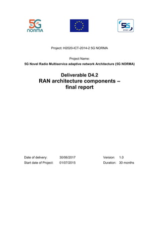
2.1 RAN Slicing
Figure 2-1: Three RAN slicing options
Service
Service
NAS
Service
Service
NAS
Service
Service
NAS
Service
Service
NAS
Service
Service
NAS
Service
Service
NAS
Network
Control
Layer
SDM-C
Multiplexing
Policy
Function
(slice
specific)
SDM-X
Multiplexing
Policy
Function
(across
multiple
slices)
Network
Management
and
Orchestration
(MANO)
Core
Network
Domain
Radio
Access
Network
Domain
Option 2:RAN slicingwith slice-
specific PDCP/RLCandRRCper
slice
Option 3:RAN slicingwith
sharedRAN (similarto 3GPP
MOCN)
Option 1:RAN slicingwith slice-
specific RAN stack and shared
lower PHY (TP specific)
PHY User
MAC
PDCP
RLC
MUX
PHY Cell
PHY TP
PHY User
MAC
PDCP
RLC
PHY Cell
RRC (User/Cell)
IF* IF*
Slice 2
MNO2, IoT
PDCP
RLC
MUX
PHY (TP/Cell/User)
MAC
PDCP
RLC
IF* IF*
Slice 2
MNO2, IoT
Slice 1
MNO1,MBB
RRC
Slice 1
MNO1,MBB
MUX
PHY (TP/Cell/User)
MAC
IF* IF*
Slice 2
MNO2, IoT
Slice 1
MNO1,MBB
RLC
PDCP
QoS Ctrl
RRC
QoS Ctrl
RRC Slice
QoS Ctrl QoS Ctrl
RRC Slice
QoS Ctrl QoS Ctrl
RRC (User/Cell)
18. 5G NORMA Deliverable D4.2
Dissemination level: Public Page 18 / 158
In [5GN-D41], we introduced three options for RAN slicing1
that are considered by 5G NORMA.
Those three options differ by the degree of freedom offered for slice-individual customization, as
well as the required complexity for implementation. In the following, all three options, jointly
shown in Figure 2-1, are summarized; afterwards, the functional architecture for each RAN slicing
option is detailed in the sub-sequent sections. All function blocks are described in detail later in
Chapter 4 (also cf. Annex B and the List of Acronyms and Abbreviations above).
Option 1: Slice-specific RAN. The first option in Figure 2-1 refers to the case where only
transmission point specific functionality is shared among network slices while all other
functionality is instantiated specifically for each network slice. In this case, the
maximum degrees of freedom are achieved because each network slice may be
customized down to the physical layer. On the other hand, this option requires a tight
synchronization of the multi-tenancy policies applied to the common part and the per-
slice (dedicated) implementation, which may limit the achievable multiplexing gains
considerably. Examples for this option include the possibility for implementing
different radio access technologies within the same shared spectrum, e.g., 4G and 5G,
or to separate two deployments while still exploiting multiplexing gains.
Option 2: Slice-specific radio bearer. The second option in Figure 2-1 refers to sharing
transmission point (cell) specific and user specific functionality, i.e., PHY and MAC in
the data layer, and RRC in the control layer. This options slightly reduces the
complexity because resource multiplexing would be implemented across all network
slices and each network slice makes use of the same efficient flexible RAN
implementation; on the other hand, each network slice may still customize the operation
through configuration and parameterization based on the service requirements and each
network slice may still implement its own QoS control (QoS prioritization). Hence, this
option provides a reasonable trade-off of flexibility and complexity.
Option 3: Slice-aware shared RAN. The third option in Figure 2-1 refers to a deployment where
the complete RAN is shared by multiple tenants. This option is close to existing
solutions such as eDECOR [23.711] although in our case, multi-slice connectivity is
considered. Hence, one UE may be connected to more than one network slice. In
addition, the SMDC Coordinator (SDM-X, cf. Section 4.1) is quite powerful in this
option because a significant part of the RAN functionality may be implemented as
applications on top of the SDM-X.
The above options are not meant to cover all possible RAN slicing options but they cover three
setups of particular interest, each providing different benefits and requiring different degrees of
complexity. In addition, the different options may co-exist, e.g., Option 1 may multiplex network
slices customized down to the PHY layer with sets of network slices implemented using Option
2 and a set of Option 3 slices can be multiplexed either also with Option 1 or with Option 2, then
sharing the lower part up to MAC with other Option 2 slices.
1
Network slicing, in general, refers to sharing a common infrastructure between multiple logical network instances
(see also [5GN-D32]). In this context, a tenant can be a mobile network operator, or companies from vertical
industries requesting and using a network slice instance.
19. 5G NORMA Deliverable D4.2
Dissemination level: Public Page 19 / 158
2.1.1 Slice-specific RAN (Option 1)
Figure 2-2: Functional control and data layer architecture, RAN slicing Option 1 (slice-
specific RAN)
The functional architecture for the first option is shown in Figure 2-2. The depicted lowercase
letters (m, r, c, e, n, s, p, g, q, t) indicate the exchange of information during operation between
the respective function blocks. A letter at the bottom of one block relates to the same letter at top
of other block(s), implying a controlling logic and controlled agent relation. The uppercase letters
(C, U, M) represent proprietary control interfaces between distributed control and data layer (for
the rationale and details cf. Section 4.2).
Transmission (and reception) point specific functionality is shared across network slices while all
other functionality is implemented specifically by each network slice. This choice may coincide
with the choice of functional split between the access point (AP) respectively more precisely the
distributed unit (DU) located at the antenna site and the central unit (CU), i.e., the SDM-X
functionality may be executed at the DU controlling the PNFs, while the slice-specific
implementation would be implemented at the centralized processor using partly VNFs.
Alternatively, the SDM-X may be more centralized controlling multiple DUs depending on the
connectivity properties between SDM-X and PHY TP.
The implementation of Option 1, in particular the SDM-X, is very challenging because each slice
may implement an own slice-specific scheduler. The resource management of these schedulers
and the multi-tenancy policies enforced by the SDM-X need to be kept consistent, which requires
closed-loop feedback between the SDM-X and per-slice schedulers. However, this may be
alleviated by reserving fixed resources per slice, such as for legacy systems, which would also
limit the multiplexing gain significantly.
Hence, the interface between common and dedicated part would mainly cover radio resource
management information in order to allow for multiplexing the different network slices in the air
interface, i.e. no post-processing of time/frequency domain symbols necessary. This covers also
inter-cell coordination algorithms such as ICIC, which may be implemented in each slice but need
to be coordinated with the SDM-X, e.g., ensuring similar resource allocation of the same network
slice at different APs.
5GNORMA-SDMC-NF
Control
layer
Data
layer
Common Dedicated
SDM-C
SDM-X
SON
s
NAS
Control
n
PHY
TP
r
PHY
User
U,M
MAC
U,M
PDCP
Split
Bearer
U,q
Transp. (SDN)
MAC
CA
U,M
Transport (SDN)
eMBMS
User
e,q
RRC
User
RRC
mmW U
RAT/Link
sel.
M,c,s,p,r,
n,g
RRC
Cell
M,c,e,n
C
Interfaces distributed control
t,c,s,… Info exchange SDMC-enabled control
C,U,M
common/dedicated per slice
standard/modified by 5G NORMA
common/dedicated control app
control/data layer interfaces
Distributed
PDCP
U,q
RLC
U,q
PHY
Cell
C,M
NAS
n,q
MEC
Application
Service
Data
Network
GDB
g
mMTC
RAN
Cong.
Ctrl
c
g
eMBMS
Control
e
n
QoS
Control
q
n
RAN
Paging
p
s
Multi-ten.
Policy
t
RRC
Cell
r
m
MAC
Scheduling
M,t,e,q
M
QoS
Scheduling
5GNORMA-SDMC-NF
5GNORMA-SDMX-NF
5GNORMA-SDMC-SDMX
20. 5G NORMA Deliverable D4.2
Dissemination level: Public Page 20 / 158
Furthermore, Figure 2-2 shows that RRC Cell is located in the common and dedicated part. This
reflects the possibility of individual RRC Cell implementations in each network slice, while the
set of configuration parameters pertaining to PHY TP (e.g. enabled antenna elements, total
transmission) is under common control. Slice-specific RRC Cell may be necessary in the case of
legacy systems that are not slicing-capable. In addition, the RRC User function block is
implemented in each network slice, i.e., also user mobility would be implemented in a slice-
specific way. Hence, if a user connects to multiple slices of Option 1, it must be able to support
multiple RRC instances.
A key enabler for this option, and for the following RAN slicing options, is a flexible RAN
numerology as investigated by H2020 FANTASTIC-5G, cf. Section 3 in [F5G-D32]. Such a
flexible numerology allows for allocating radio resources and configuring their usage in a service-
specific manner. Hence, each network slice representing a different service may use individual
numerologies in order to adjust the air interface to its requirements. As such, using RAN slicing
and this flexible numerology, very different networks, i.e. end-to-end logical networks, may be
implemented in the same spectrum in order to optimize the radio resource usage.
2.1.2 Slice-specific radio bearer (Option 2)
Figure 2-3: Functional control and data layer architecture, RAN slicing Option 2 (slice-
specific radio bearer) (function types)
The second RAN slicing option is illustrated in Figure 2-3 where both the transmission point and
user specific part of PHY and MAC is shared across network slices, and the service (or bearer)
specific part is implemented in each network slice. Hence, in this option, the individual network
slices rely on the same radio access technology but customize their operation at lower layers
through parameterization and at higher layers through customized implementation.
In this option, the MAC layer and with it the TTI-based scheduling is part of the shared functions.
This tighter control of the radio resources may increase the achievable multiplexing gains and
alleviates the consistency requirements compared to Option 1. On the other hand, the interface
between the shared and dedicated part is more complex because more interactivity between both
parts is required, e.g., the actual resource assignments in the shared part must be reflected by the
Common Dedicated
Control
layer
Data
layer
5GNORMA-SDMX-NF
5GNORMA-SDMX-NF
5GNORMA-SDMC-SDMX
RLC
U,q
PDCP
U,q
SDM-C
SDM-X
mMTC
RAN
Congestion
Control
c
SON
s
NAS
Control
n
Multi-ten.
Scheduling
t
PHY
TP
C
PHY
User
U,M
MAC
U,M
RRC
Slice
r
PDCP
Split
Bearer
r,q’
Transport (SDN)
MAC
CA
U,M
Transport (SDN)
eMBMS
User
e,q’
RRC
User
RRC
mmW
U
RAT/Link
sel.
M,c,s,p,r,
n,g
RRC
Cell
M,c,e,n
C
Interfaces distributed control
t,c,s,… Info exchange SDMC-enabled control
C,U,M
common/dedicated per slice
standard/modified by 5G NORMA
common/dedicated control app
control/data layer interfaces
Distributed
PDCP
r,q’
RLC
r,q’
PHY
Cell
C,M
NAS
n,q’
MEC
Application
Service
Data
Network
GDB
g
g n
eMBMS
Control
e
n
QoS
Control
q’
n
RAN
Paging
p
s
QoS
Control
q
q’
MAC
Scheduling
M,t,e,q
M
QoS
Scheduling
5GNORMA-SDMC-NF
21. 5G NORMA Deliverable D4.2
Dissemination level: Public Page 21 / 158
RLC layer in the dedicated part (segmentation, ARQ), channel measurements need to be
exchanged, etc. All this information needs to be handled by this interface between shared and
dedicated part. Again, this interface may coincide with the interface between the DU executing
the common part and the edge/central cloud executing the dedicated part. Consequently, also the
SDM-X in Option 2 is more complex than in Option 1 but it also offers more degrees of freedom
for resource sharing among slices as well as opportunities for future evolution. While the
MAC Scheduling function is element of the common part and therefore does not allow for
customization by the tenant, the QoS Control function is element of the dedicated part and offers
the possibility for slice-specific control based on policies and constraints customized by the
tenant. The information about the individual services and their QoS requirements would be
provided to the MAC Scheduling function block respectively its QoS Scheduling subblock, which
then enforces those QoS constraints as part of its multi-service framework.
Compared to Option 1, the RRC Cell and RRC User function blocks are common to network
slices of one UE and therefore the mobility handling is significantly simplified. The PDCP
function block is part of the dedicated network slice implementation and as such also the security
context in the RAN, i.e. the tenant may implement the security functions of each network slice.
Furthermore, the RLC and PDCP function blocks are listed both on the common and dedicated
part. The function blocks in the common part are used for the control signalling, which is user
specific, and the RLC/PDCP function blocks in the dedicated part are used for the data layer,
which is service/bearer specific.
Figure 2-4: Integration of RAN slicing Option 2 and multi-connectivity based on MAC and
PDCP layer, respectively
MUX
(RRCUser/Cell)
MUX
(RRCUser/Cell)
Slice
MNO 1, MBB
Core
network
domain
Radio
access
network
domain
AirInterface
PDCP
PHY A
Service
Service
IF*
Example: Option 2 combined
with PDCP based MC (split
bearer)
MAC A
RLCA.1 RLCB.1
QoSControl
PHY B
MAC B
RRC Slice
Slice
MNO 2, IoT
PDCP
Service
Service
IF*
RLCA.2 RLCB.2
QoSControl
RRC Slice
Slice
MNO 1, MBB
PDCP
PHY A
Service
Service
IF*
Example: Option 2 combined
with MAC-based MC (carrier
aggregation)
MAC
QoSCtrol
PHY B
RRC Slice
Slice
MNO 2, IoT
PDCP
Service
Service
IF*
QoSControl
RRC Slice
RLC RLC
PDCPSplit PDCPSplit
MUX
(RRCUser/Cell)
iMUX
22. 5G NORMA Deliverable D4.2
Dissemination level: Public Page 22 / 158
Furthermore, in this option most ingredients of a flexible RAN are included in the common part
such as the flexible numerology mentioned before, carrier aggregation, RRC state handling, etc.
Hence, it is not necessary that each slice needs to reimplement this flexible RAN functionality
but may use one efficient implementation while customization through parametrization is still
possible. In addition, multi-connectivity can be well integrated with this RAN slicing option as
illustrated in Figure 2-4.
2.1.3 Slice-aware shared RAN (Option 3)
Figure 2-5: Functional control and data layer architecture, RAN slicing Option 3 (shared
RAN)
The third option is illustrated in Figure 2-5 and corresponds to the case where the RAN is a
common resource for network slices. This case is similar to the ongoing discussion in 3GPP SA
[23.799], which considers slicing only in core network and treats the RAN as a common resource
[23.501]. In 3GPP LTE/SAE, eDECOR has been introduced which allows for implementing
dedicated core networks such that each UE may be connected to a customized core network.
Furthermore, 3GPP LTE/SAE allows for connecting a UE to multiple PDNs while using the same
serving gateway (S-GW). This is the main limitation, which is alleviated by 5G where each UE
may be connected to more than one network slice (i.e., core network). Hence, this option would
provide seamless migration and requires minimal changes to current standards.
Common Dedicated
5GNORMA-SDMC-SDMX
Control
layer
Data
layer
5GNORMA-SDMX-NF
5GNORMA-SDMX-NF
SDM-C
SDM-X
SON
s
NAS
Control
n
Multi-ten.
Scheduling
t
PHY
TP
C
PHY
User
U,M
MAC
U,M
PDCP
Split
Bearer
U,q
Transport (SDN)
MAC
CA
U,M
Transport (SDN)
eMBMS
User
e,q
RRC
User
RRC
mmW
U
RAT/Link
sel.
M,c,s,p,r,
n,g
RRC
Cell
M,c,e,n
C
Interfaces distributed control
t,c,s,… Info exchange SDMC-enabled control
C,U,M
common/dedicated per slice
standard/modified by 5G NORMA
common/dedicated control app
control/data layer interfaces
Distributed
PDCP
U,q
RLC
U,q
PHY
Cell
C,M
NAS
n,q’
MEC
Application
Service
Data
Network
GDB
g
mMTC
RAN
Congestion
Control
c
g
eMBMS
Control
e
n
QoS
Control
q’
n
RAN
Paging
p
s
QoS
Control
q
q’
MAC
Scheduling
M,t,e,q
M
QoS
Scheduling
5GNORMA-SDMC-NF
23. 5G NORMA Deliverable D4.2
Dissemination level: Public Page 23 / 158
2.1.4 Exemplary use of RAN Slicing
Figure 2-6: Exemplary deployment using RAN slicing in the context of an industrial
campus deployment
Figure 2-6 shows exemplarily different network slices that may co-exist within the same
deployment such as an industrial campus network. In this particular example, we stagger different
RAN slicing options, i.e. RAN slicing Option 1 multiplexing data from two network slices and
the common part of RAN slicing Option 2.
In particular, the following slices are shown in Figure 2-6 (note that those are examples which
may have different requirements or implementations in other scenarios):
• 4G (legacy systems): This network slice represents a legacy network such as 4G
which is integrated into the same infrastructure. In existing deployments, it is unlikely
the installed terminals could be replaced all at once, but those terminals will rather
co-exist with new deployments utilizing 5G technologies enabling novel service.
Hence, the architecture needs to integrate both existing standards as well as upcoming
technologies, which is reflected by RAN slicing Option 1.
• Critical IoT slices may be implemented within factories for novel and critical IoT
services [5GPPPWP] such as wireless robot control. They may also use different
radio access technologies in order to satisfy the requirements and constraints imposed
by the use cases and requiring customization down to the PHY layer. Compared to
other slices, they may not require NAS signalling (or only very limited).
• Massive IoT slices may not need customized PHY and MAC layer which also
increases the deployment flexibility of sensor nodes as well as reduces their costs
because non-proprietary technologies are used. The required access may only be local
at the factory in order to guarantee data privacy. The slice may be (partly) operated
by the industrial tenant, e.g., data layer provided by tenant and control layer (partly)
provided by third party (e.g. MNO).
QoS Ctrl
QoS Ctrl
RRC Slice
Core
Network
Domain
Radio
Access
Network
Domain
PHY User
MAC
PDCP
RLC
MUX
PHY Cell
PHY TP
PHY User
MAC
PDCP
RLC
PHY Cell
QoS Ctrl QoS Ctrl
NAS
NAS
IF* IF*
eMBB
(public
access)
RRC
4G
(legacy
support)
MUX
NAS
(Service)
NAS
(Service)
NAS
(Service)
NAS
(Service)
IF* IF*
Massive IoT
(Tenant 2)
Massive IoT
(Tenant 1)
PDCP
RLC
QoS Ctrl
RRC Slice
NAS
NAS
IF*
Massive IoT
(local
access)
PHY User
MAC
PDCP
RLC
PHY Cell
QoS Ctrl
IF*
RRC
Critical IoT
(robot
control)
RRC User/Cell
PDCP
RLC
MUX
24. 5G NORMA Deliverable D4.2
Dissemination level: Public Page 24 / 158
• eMBB slice may be provided by MNO but operated only on the factory ground in
order to provide data access into the public network, e.g., for video telephony and
similar services.
• The two massive IoT slices at the right may be operated by the MNO in order to
provide data access to third party companies operating equipment on the factory
ground, e.g. logistics companies tracking goods. The slices may exploit additional
infrastructure on the factory grounds in order to improve coverage while the factory
owner may offer these services jointly with the MNO.
[5GN-D32] and [5GN-D33] provide more detailed analyses of business models and stakeholder
roles which would affect the above architecture.
2.2 Standardization relevance and potential
This section does not aim to provide an architecture comparison between 5G NORMA and 3GPP
5G systems in general, rather to use 3GPP 5G as a best possible reference to show standardization
relevance and potential of 5G NORMA innovations. Note that 5G NORMA is primarily a
research oriented project and 5G NORMA does not aim to specify complete network systems for
5G at the first place.
The baselines of 3GPP next-generation radio access network (NG-RAN) are being captured in
[38.300]. As depicted in Figure 2-7, NG-RAN consists of gNBs and/or eNBs, providing the u-
plane and c-plane (named d-layer and c-layer in 5G NORMA) protocol terminations for the radio-
interfaces towards the UE. The gNBs and eNBs may be interconnected with each other via Xn
interface. The gNBs and eNBs are connected to 5G core network (5GC) via NG interfaces, more
specifically to AMF (Access and Mobility Management Function) via the NG-C interface and to
UPF (User Plane Function) via the NG-U interface [23.501]. The functional split between NG-
RAN and 5GC is given in Figure 2-8.
Figure 2-7: Overall architecture of 3GPP 5G network (Figure 4.1-1 of TS 38.300)
gNB gNB
gNB
NG
NG
N
G
N
G
Xn
X
n
X
n
NG-RAN
5GC
AMF/UPF AMF/UPF
25. 5G NORMA Deliverable D4.2
Dissemination level: Public Page 25 / 158
Figure 2-8: Overview of functional split between 3GPP NG-RAN and 5GC (Figure 4.2-1 of
TS 38.300)
A realization of the 3GPP 5G system on 5G NORMA would have, for the 5GC part, the control
functions of AMF and UPF implemented as a set of SDM-C applications, e.g. NAS Control would
be part of such a set. The UPF is part of the NAS d-layer function block. The NG-RAN, i.e. the
functions of the gNB, would be provided by the following 5G NORMA function blocks:
• Radio Admission Control: Multi-tenant Scheduling SDM-X Application (Multi-tenant
Policy for RAN Slicing Option 1)
• Connection Mobility Control: Mobility-Management SDM-C Application [5GN-D52]
• RB Control and Measurement Configuration & Provision: RRC User and additionally
RRC slice for RAN slicing Option 2
• Inter-cell RRM and Dynamic Resource Allocation (Scheduler): MAC Scheduling
distributed control function, with tenant-specific control via SDM-X applications Multi-
tenant Scheduling and SDM-C/X application QoS Control
Further aspects of NG-RAN architecture and interfaces can be found in [38.801]. In particular,
the gNB architecture consists of a central unit (CU) and one or more distributed unit (DU)
connected to CU via Fs-C and Fs-U interfaces for C-plane and U-plane, respectively, as shown in
Figure 2-9.
3GPP has considered various options for reconfigurable RAN functional split between CU and
DU, as shown in Figure 2-10. 5G NORMA omits split Options 3 and 5 within RLC and MAC,
respectively, and High PHY, Low PHY and RF PHY relate to PHY User, PHY Cell and PHY TP
of 5G NORMA, respectively.
For multi-connectivity architecture, 3GPP has been focusing on RAN level integrated dual
connectivity between NR and LTE. RAN supports for network slicing are also addressed in
[38.801], focusing on enabling selection of network slice and CN instance by a gNB. NG-RAN
also incorporates supports for UEs in inactive mode, QoS flow management and mapping to data
radio bearers as well as new challenging services such as ultra-reliable and low latency
communications (URLLC).
internet
gNB
RB Control
Connection Mobility Cont.
Measurement
Configuration & Provision
Dynamic Resource
Allocation (Scheduler)
AMF
UPF
Inter Cell RRM
Radio Admission Control
NG-RAN 5GC
Mobility Anchoring
Idle State Mobility
Handling
NAS Security
SMF
UE IP address
allocation
PDU Session
Control
PDU Handling
26. 5G NORMA Deliverable D4.2
Dissemination level: Public Page 26 / 158
Figure 2-9: The gNB architecture with CU and DUs (Figure 11.1.3.8-1 of TR 38.801)
Figure 2-10: Functional split options between CU and DU (Figure 11.1.1-1 of TR 38.801)
In a high-level comparison between 5G NORMA and 3GPP 5G access network architectures, the
following can be observed:
• Both are sharing views in many aspects, including flexible RAN functional split or
function decomposition, multi-connectivity with NR-LTE tight interworking and RAN
level integration, supports for network slicing, UE inactive state, QoS flow and radio
bearer mapping and management.
• 5G NORMA, however, has more extensive considerations on SDN/SDMC-enabled
architectures and flexible multi-service and multi-tenancy supports via means of network
slicing, resulting in a more centralized SDMC based architecture. This enables and
facilitates different RAN slicing innovations with more flexible and dynamic adaptive
function decomposition, as presented in Section 2.2.
The following Table 2-1 provides a more insightful view from 5G NORMA innovation
perspective, which of the 5 5G NORMA overall objectives they address and how in this respect
they compare to the approach 3GPP has taken. As can be seen, 3GPP in many aspects took similar
approaches to 5G NORMA. Most notable differences stem from the different approaches of
5G NORMA and 3GPP. While 5G NORMA start from highest possible flexibility and reduces
where technically necessary, 3GPP starts from with the legacy approach of a network of entities
and a RAN core split and adds flexibility as needed for the short term targets. The results become
visible especially at the RAN, where 5G NORMA applies its SDMC concept and offers RAN
CU
Fs-C
DU DU
Fs-U Fs-C Fs-U
gNB
PDCP
Low-
RLC
High-
MAC
Low-
MAC
High-
PHY
Low-PHY
PDCP
Low-
RLC
High-
MAC
Low-
MAC
High-
PHY
Low-PHY
Option 5
Option 4 Option 6 Option 7
Option 2
Option 1
RRC
RRC
RF
RF
Option 8
Data
Data
High-
RLC
High-
RLC
Option 3
27. 5G NORMA Deliverable D4.2
Dissemination level: Public Page 27 / 158
slicing, while 3GPP, at least the first phase of 5G standardization, just adds support for network
slicing to NG-RAN, i.e. a non-sliced RAN comparable to RAN slicing Option 3 but which lacks
the programmability offered through SDMC and accordingly the means for slice-individual
customization of the RAN.
Table 2-1: 5G NORMA innovations vs. 3GPP 5G, grouped according to the 5 key
innovations
Innovations 5G NORMA 3GPP 5G
Adaptive
(de)composition and
allocation of mobile
network functions
• Flexible and cloud-RAN
based approach
• Multi-RAT MC with tight 5G-
LTE interworking
• More dynamic SON based
• Flexible and cloud-
RAN based approach
• Multi-RAT MC with
tight 5G-LTE
interworking
• Semi-static
reconfigurable
Software-defined mobile
network control
(SDMC),
• NFV- and SDMC-based c/d-
layer to realize a slice-
individually customizable
network of functions
• NFV is more visible in
5GC
• Certain legacy design
principles are kept to
allow RAN and 5GC
evolve independently
as much as possible
Joint optimization of
mobile access and core
network functions
• RAN support for in-bear QoS
differentiation
• RAN support for context
aware service delivery (multi-
service radio access)
• UE in INACTIVE and RAN
paging as defined by the UCA
concept
• Integration of mmAP clusters
• Through functional
split between NG-
RAN and 5GC, e.g.,
RB control and some
QoS flow management
is moved to gNB
• Feature specific
optimizations, e.g.,
supports for MTC, UE
in INACTIVE and
RAN paging, RAN
support for context
aware service delivery
Multi-service- and
context-aware
adaptation of network
functions
• URLLC support
• Multi-service radio access and
high data rates via mmAPs
• URLLC support
Mobile network multi-
tenancy
• Network slicing including
RAN slicing
• Extensive considerations on
characterization/categorization
of tenants for future mobile
networks
• Network slicing for
5GC and NG-RAN
support for network
slicing
28. 5G NORMA Deliverable D4.2
Dissemination level: Public Page 28 / 158
More specifically, 5G NORMA partners have (so far) submitted 21 contributions to 3GPP RAN2
and RAN3, the two 3GPP specification groups that the innovations of WP4 mostly apply to. The
complete list of standards contributions will be documented at the end of the 5G NORMA project
with [5GN-D72]. These standards contributions express 5G NORMA views and findings in some
selected topics, including:
• Support of novel services in 5G beyond mobile broadband, in particular ultra-reliable low
latency communications (URLLC) ([5GN-D41] Section 1.3 innovations 1, 3, 5 and 13);
• Requirements and principles for network slicing, including isolation between network
slices and how these requirements can be supported in slicing the RAN ([5GN-D41]
Section 3.3 and Section 1.3 innovation 2);
• RAN slicing, in particular radio resource isolation ([5GN-D41] Section 3.3);
• Multi-connectivity supports including tight interworking between LTE and 5G NR
([5GN-D41] Section 1.3 innovations 1, 3, 4, 5 and 7);
• RAN level QoS flow management and PDCP relocation ([5GN-D41] Section 1.3
innovations 11 and 12);
• Support of UE in an INACTIVE state with RAN level paging ([5GN-D41] Section 3.2.1.4
and Section 1.3 Innovation 6)
• Multi-connectivity support, as described in Section 6.1;
• RAN support for network slicing in RAN slicing Option 3, described in Section 2.1.3,
with two innovations to enable the UE to access multiple network slices simultaneously:
(i) PDCP multiplexing of service flows from different network slices and (ii) coordinated
dynamic scheduling and semi-persistent scheduling based resource allocations. These are
described in Part II Chapter 17;
• SON based flexible configuration of 5G RAN protocol stacks aims for possible support
of more flexible and dynamic on-the-fly adaptation of the RAN function decomposition,
as compared to rather semi-static reconfigurable options for RAN functional split
between CU and DU (Figure 2-10) ([5GN-D41] Section 1.3 Innovation 9);
• UE agent based end-to-end connection decomposition concept, which is directly related
to and goes beyond 3GPP Rel-14 study on context aware service delivery in RAN for
LTE [36.933]. This innovation also provides an effective means for integrating and
leveraging lower data rate satellite communications into 5G network systems ([5GN-
D41] Section 1.3 Innovation 10).
29. 5G NORMA Deliverable D4.2
Dissemination level: Public Page 29 / 158
3 Use of functional decomposition for service
adaptation
A fundamental aspect of flexible architecture is its ability to adapt to multiple services with
different requirements, yet with minimal or no infrastructure amendments. In this regard, function
decomposition plays an important role in tailoring the network operation to its specific needs,
thereby, attaining the desired adaptability in terms of allocating the network functions and
resources based on the requirement and deployment characteristics.
The remainder of this section is divided into three major parts. First, the concept of flexible
function selection and placement is put forward, thereby highlighting the fact that different slices
may involve different network functions located at different places. Second, the notion of multi-
service radio access is analysed, elaborating on the conceptual differences between multi-
connectivity, multi-tenancy as well as multi-service. Third, the above analyses are complemented
with security considerations.
3.1 Function selection and placement
Conceptual relation to network slicing
As discussed in Chapter 2, the concept of flexible network design entails the ability of network
functions to be deployed in an adaptive fashion. This practically means that, in contrast to
conventional network architectures where network functions are pre-configured, network
functions are dynamically configured both in terms of functional operation and physical location.
In fact, with the flexible design approach embraced in 5G NORMA, a new dimension in network
architecture is offered, where functions are systematically extracted from a pool of resources and
utilised exactly when and where they are needed.
Such network design is in line with the architectural approach of network slicing. In particular,
the fundamental conceptual element of network slicing is the separation of services into
independent logical networks. In this respect, the 5G NORMA architecture comprises
decomposed functional elements, which can be allocated on demand, such that different slices are
associated with different network function blocks. Moreover, the diverse requirements of network
slices (for example, in terms of latency of end-to-end services) imply that the requirements on the
physical placement of individual network functions also vary.
Figure 3-1: Function selection and placement (RAN slicing Option 2)
Missioncritical slice
Low latency slice
Broadband slice
PHY Cell
PHY TP
PHY User
SDM-C
SDM-X
PHY Cell
PHY TP
PHY User
PDCP
PHY Cell
PHY TP
PHY User
MAC
PDCP
Edge cloud
PHY Cell
PHY TP
PHY User
PHY Cell
PHY TP
PHY TP
(transparent)
RLC UM
PDCP
MAC
MAC CA
RRC Cell
Distributed
control
RRC User
MAC
MAC
Scheduling
PHY User
PHY Cell
PHY User
SDM-C
SDM-X
RRC Cell
Distributed
control
RRC User
MAC
Scheduling
SDM-C
SDM-X
RRC Cell
Distributed
control
RRC User
MAC
Scheduling
RLC
PDCPSplitBearer
(distribution)
RLC
MAC
MAC
c-layer
d-layer c-layer
d-layer c-layer
d-layer
Edge cloud
Edge cloud
RLC AM
RLC AM
PDCPSplitBearer
(duplication)
Antenna
site
Antenna site
Antenna
site
30. 5G NORMA Deliverable D4.2
Dissemination level: Public Page 30 / 158
A closer look on flexible function allocation
We distinguish two basic levels of flexible function allocation, namely function selection and
function placement. Function selection refers to the set of the network functions deployed in a
slice, thereby reflecting the ability of the 5G NORMA architecture to construct the functional
operation of a network slice via function blocks. Function placement refers to the physical
network locations, where those functions are deployed, again on the basis of a particular network
slice with given requirements.
The above two levels of flexible function allocation are illustrated in Figure 3-1. In particular, we
map the concepts of function selection and function placement onto the principal types of network
slices anticipated for 5G, namely mobile broadband, low latency and mission critical slice. As
can be observed from Figure 3-1, different slices comprise different set of functions placed in
different parts of the network, aiming to better meet the diverse requirements imposed. Next, we
treat each of the three slice types separately and elaborate on the effect of function selection and
placement on the considered architecture, focusing on the data layer.
QoS control per network slice
In line with the above consideration, the network will be designed as a multi-service adaptive
mobile network, where the network resources fulfil the service requirements in a flexible and
dynamic way per each network slice.
The QoS Control function block will be in charge of the network monitoring and configuration.
For the QoS monitoring tasks, two approaches can be considered: ‘intrusive’ and ‘non-intrusive’.
The non-intrusive methods are purely based on monitoring the already available QoS parameters
(i.e., latency, jitter, or packet loss). On the other hand, intrusive methods are based on installing
specific purpose SDM-C applications to get additional QoS parameters. Other solutions are
focused on including new network functions (e.g., network probes and analysers, deep packet
inspectors, etc.) that are responsible for capturing the traffic from a certain service and analysing
its performance.
A QoS agent (specific piece of software) in network function blocks (VNFs, PNFs) will monitor
the QoS status at run time, e.g., connection speed or packet loss rate. When some monitoring
parameter does not fulfil the proper values, an event will be generated and captured by the SDM-
C/X and distributed control functions. Then, the QoS Control function block will receive the
reports of these events from the controllers and will aggregate and analyse the data, enforcing
new configuration actions (resource re-scheduling, new resource assignments) on the network
function blocks to meet the QoS requirements of each mobile service according to the assessment
results. The adjustment happens when the evaluation result violates a threshold that is defined by
service requirements.
The broadband slice
Function selection aspect of flexible design: The broadband slice is designed to serve applications
associated with high data rate transmissions. This means that the broadband slice involves
network functions, the primal use of which is to increase the overall throughput. Hence,
considering the network functions analysed in deliverable D4.1 [5GN-D41], the broadband slice
would involve the PDCP split bearer as well as the MAC carrier aggregation (CA) function blocks
from the data layer domain. Of course, any combination of the different transmission legs is
possible. For instance, the MAC CA function can be applied to one or more components of the
bearer, which is split in PDCP by means of the PDCP split bearer function. In Figure 3-1, an
exemplary implementation of function selection for the broadband slice can be observed in the
left part.
Function placement aspect: Beside function selection, a typical example of locating network
functions based on the corresponding broadband service is also depicted in the left part of Figure
3-1. Specifically, we notice that the PDCP and PDCP split bearer blocks are located at the edge
cloud. This location has been chosen to facilitate multi-connectivity as well as to minimise the
31. 5G NORMA Deliverable D4.2
Dissemination level: Public Page 31 / 158
mobility signalling to the core network [Rav16]. We also notice that, in contrary to PDCP
functionalities, RLC as well as lower layers of the protocol stack need to be co-located at the
antenna site. This is due to their real-time operation, implying a synchronous interaction between
one another and thus a low latency inter-layer communication.
The low latency slice
Function selection: Contrary to the broadband slice, the main requirement for the low latency
slice type is not, in principal, high data rate. In fact, with the exception of virtual reality services
where both latency and throughput need to be taken care of, low latency applications are usually
associated with machine-type packets of bursty nature, the size of which is considerably smaller
than that of the usual packet size of MBB applications. This means that multi-connectivity is not
a crucial element of the low latency slice and is therefore not included. This is depicted in the
middle part of Figure 3-1. It is also important to notice that for slices supporting ultra-low latency
requirements, the outer Automatic Repeat request (ARQ) function is also not included in the RLC
part of radio stack, thus the RLC operates in the unacknowledged mode. The RLC UM is thus
included in this slice.
Function placement: The low latency slice entails special, tight requirements in terms of the end-
to-end latency. This demands for the realization of the network functions in a location which is
as close to the antenna site as possible. As a result, there is no use of the edge cloud for this slice;
instead, all network functions are placed in the (logical) edge cloud co-located at the antenna site
(which may be a small NVFI integrated into the DU), including those supporting PDCP
functionalities. In other words, the edge cloud is unused or “transparent” for low latency slices.
The mission critical slice
Function selection: This slice is designed to mainly support services with ultra-high reliability
levels2
. Such reliability levels are considerably higher than the usual values in LTE, and are
sometimes referred to as the “five nine reliability”, implying that communication should be
established without errors for at least 99.999 % percent of time. It is important to note that the
above required reliability level refers not only to the time, for which a UE is within a given area
with decent coverage, but it rather refers to the overall percentage of time, thus including also
areas with limited coverage. In other words, the requirement for high reliability here encompasses
the need for eliminating coverage holes, such that sufficient coverage is provided for 99.999 %
of UE operation. Such ultra-high reliability levels are hard to achieve with existing standards,
implying that new access techniques need to be employed. To this end, the data duplication
method has been recently proposed as a special case of multi-connectivity. Contrary to multi-
connectivity variations proposed for broadband services [36.808], data duplication involves
replicating the same message over multiple links, so as to leverage the independent streams and
increase the probability of correct reception [Rav16], [MVD16]. Of course, this would involve
modifying the functionality of PDCP, so that data streams are not split into multiple legs (as is
the case in the broadband slice) but duplicated instead, thus achieving redundancy. This implies
that special coordination needs to take place to ensure that replicas of correctly transmitted
messages are discarded, and that unnecessary further transmissions of already successfully
received data are avoided whenever possible. It is worth noting that the missing critical slice
involves the acknowledged mode in RLC (i.e., the RLC AM block in the right part of Figure 3-1),
as opposed to the RLC UM block used for the low latency slice.
Function placement: As mentioned above, high reliability entails centralised functionalities,
which are mainly associated with the coordination of the duplicate transmission. In particular,
given that duplicated and redundant streams must be jointly coordinated, a distributed
2
Although high reliability and low latency are sometimes studied on a common basis (known as ultra-reliable low
latency communication services, URLLC), ultra-high reliability entails a different architecture design which is the
focal point of this paragraph.
32. 5G NORMA Deliverable D4.2
Dissemination level: Public Page 32 / 158
implementation of the RLC and PDCP functionality would entail a large signalling overhead
between the involved nodes, which is in principle not desired. As a result, the realization of the
functions in the PDCP and RLC stack is expected to take place in the edge cloud (c.f. Figure 3-1,
right part).
3.2 Multi-service radio access
Figure 3-2: Multi-service vs. multi-tenancy and inter-tenant multi-connectivity vs (single
tenant) multi-connectivity
Multi-connectivity is the technique to connect a single user (UE) to multiple distinct instances,
i.e. cells, of a single service respectively slice, cf. Figure 3-2. Multi-tenancy, on one hand, means
that multiple tenants share common infrastructure, including sharing a single air interface
instance. On the other hand, with respect to a single UE, multi-tenancy means that the UE
connects to the services of multiple tenants concurrently, i.e. in the sense of multihoming, where
the UE connects to multiple data networks in parallel. This sharing by multiple and connection to
multiple tenants may be for the same single service, i.e. is independent of whether the service
offered by each tenant differs or not. A UE may need to concurrently support both, multi-
connectivity, the connection to multiple instances, and multi-tenancy, the connection to multiple
tenants, due to different availability of the tenants’ services at different cells or due to tenant-
individual mobility control. Such inter-tenant multi-connectivity therefore occurs, when a UE
connects to multiple slices, but the connectivity to the slices is provided to the UE via different
cells.
In 5G NORMA, each slice provides exactly one telecommunication service, e.g., eMBB or
URLLC. Having just one service per slice best captures the benefits of slicing as it allows for
optimizing a slice for its specific service as discussed in Section 3.1. Accordingly, a UE that
utilizes multiple services in parallel connects to multiple slices in parallel. On fully virtualized
network infrastructure, where specifically communication/transport resources are fully
virtualized, the same means, namely network slicing, is used to implement both multi-tenancy
and multi-service. This is typically the case in the non-access stratum. In contrast, communication
resources in the access stratum are not virtualized into generic units of transport resources. The
implementation of transport over the air interface itself is very much dependent on the service and
deployment needs and thereby represents an important differentiator for tenants. Accordingly,
implementation of transport differs between services and between tenants, notwithstanding the
use of a common implementation where this is deemed sufficient.
Access
stratum
Non-access
stratum
Service
1
Service
2
Service
3
Service
1
Service
2
Service
3
Multi-connectivity
Multi-tenancy
UE
Multi-
connectivity1 Multi-tenancy2
Multi-service2
Multi-service Multi-service
Tenant1 Tenant2 Tenant3 Tenant4
Inter-tenant
Multi-connectivity
1 single tenant, 2 single connectivity