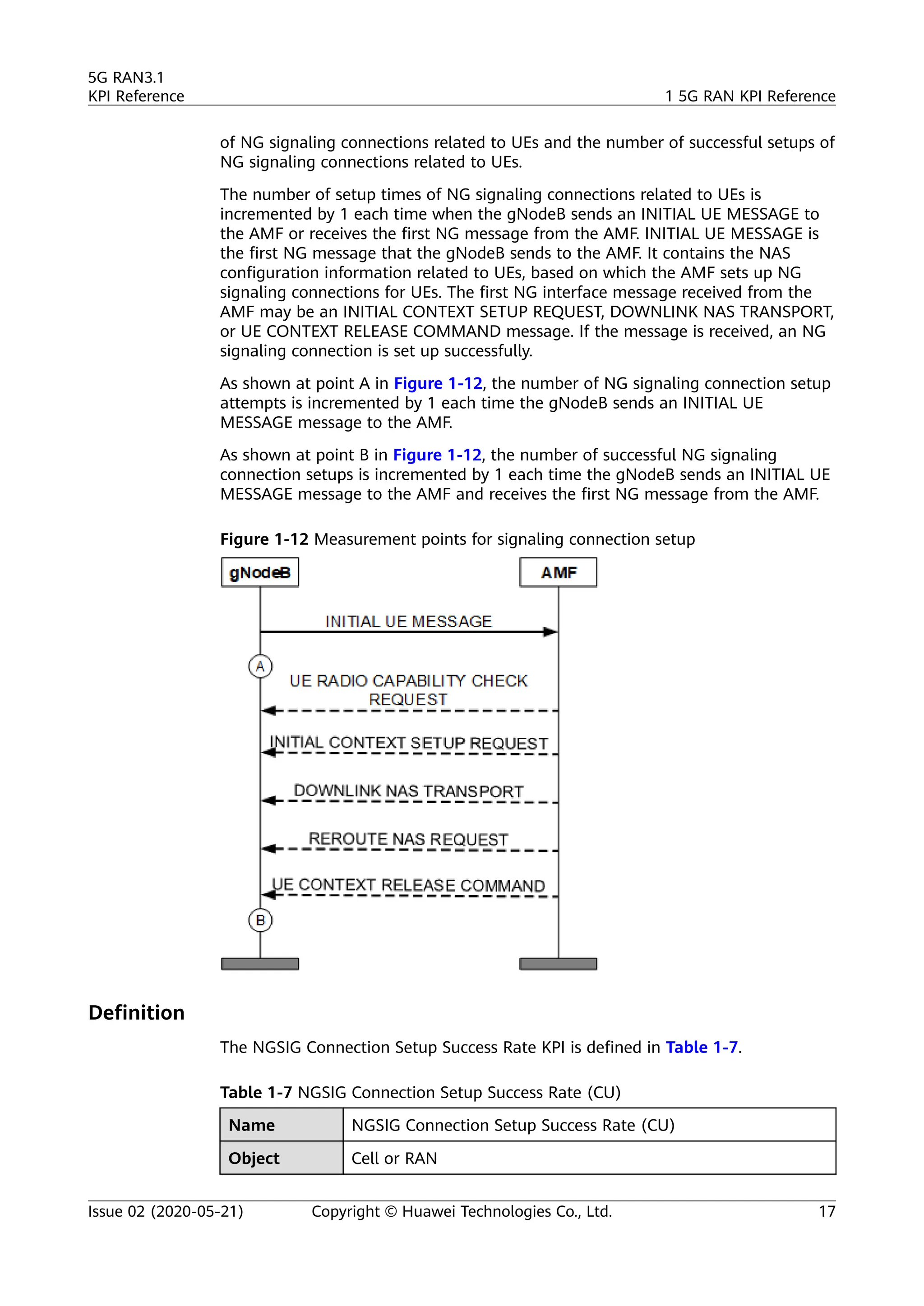
5G RAN3.1
V100R016C10
KPI Reference
Issue 02
Date 2020-05-21
HUAWEI TECHNOLOGIES CO., LTD.
Copyright © Huawei Technologies Co., Ltd. 2020. All rights reserved.
No part of this document may be reproduced or transmitted in any form or by any means without prior
written consent of Huawei Technologies Co., Ltd.
Trademarks and Permissions
and other Huawei trademarks are trademarks of Huawei Technologies Co., Ltd.
All other trademarks and trade names mentioned in this document are the property of their respective
holders.
Notice
The purchased products, services and features are stipulated by the contract made between Huawei and
the customer. All or part of the products, services and features described in this document may not be
within the purchase scope or the usage scope. Unless otherwise specified in the contract, all statements,
information, and recommendations in this document are provided "AS IS" without warranties, guarantees
or representations of any kind, either express or implied.
The information in this document is subject to change without notice. Every effort has been made in the
preparation of this document to ensure accuracy of the contents, but all statements, information, and
recommendations in this document do not constitute a warranty of any kind, express or implied.
Huawei Technologies Co., Ltd.
Address: Huawei Industrial Base
Bantian, Longgang
Shenzhen 518129
People's Republic of China
Website: https://www.huawei.com
Email: support@huawei.com
Issue 02 (2020-05-21) Copyright © Huawei Technologies Co., Ltd. i
Contents
1 5G RAN KPI Reference............................................................................................................1
1.1 Changes in 5G RAN KPI Reference....................................................................................................................................2
1.2 Accessibility KPIs...................................................................................................................................................................... 4
1.2.1 RRC Setup Success Rate (CU).......................................................................................................................................... 4
1.2.2 RRC Setup Success Rate (CU, Inactive)........................................................................................................................ 5
1.2.3 RRC Setup Success Rate (Service) (CU)....................................................................................................................... 8
1.2.4 RRC Setup Success Rate (Service) (CU, Inactive)................................................................................................... 10
1.2.5 RRC Setup Success Rate (Signaling) (CU)................................................................................................................ 13
1.2.6 RRC Setup Success Rate (Signaling) (CU, Inactive)...............................................................................................14
1.2.7 NGSIG Connection Setup Success Rate (CU)...........................................................................................................16
1.2.8 QoS Flow Setup Success Rate (CU)............................................................................................................................ 18
1.2.9 QoS Flow Setup Success Rate (CU, Inactive)...........................................................................................................21
1.2.10 QoS Flow Setup Success Rate (CU, VoNR).............................................................................................................25
1.2.11 Call Setup Success Rate (CU)......................................................................................................................................26
1.2.12 Call Setup Success Rate (CU, Inactive).................................................................................................................... 26
1.3 Retainability KPIs.................................................................................................................................................................. 28
1.3.1 Service Call Drop Rate (CU)...........................................................................................................................................28
1.3.2 Service Call Drop Rate (CU, Inactive)......................................................................................................................... 28
1.3.3 Call Drop Rate (CU, VoNR)............................................................................................................................................ 29
1.4 Mobility KPIs...........................................................................................................................................................................29
1.4.1 Intra-Frequency Handover Out Success Rate (CU)............................................................................................... 30
1.4.2 Inter-Frequency Handover Out Success Rate (CU)................................................................................................36
1.4.3 Intra-RAT Handover In Success Rate (CU)............................................................................................................... 41
1.4.4 Inter-RAT Handover Out Success Rate (NR to LTE) (CU)....................................................................................45
1.4.5 EPSFB Success Rate Based Handover (NR to E-UTRAN) (CU).......................................................................... 47
1.5 Service Integrity KPIs........................................................................................................................................................... 49
1.5.1 User Downlink Average Throughput (DU)............................................................................................................... 49
1.5.2 User Uplink Average Throughput (DU)..................................................................................................................... 49
1.5.3 Cell Downlink Average Throughput (DU).................................................................................................................50
1.5.4 Cell Uplink Average Throughput (DU).......................................................................................................................50
1.6 Utilization KPIs.......................................................................................................................................................................51
1.6.1 Downlink Resource Block Utilizing Rate (DU)........................................................................................................ 51
1.6.2 Uplink Resource Block Utilizing Rate (DU).............................................................................................................. 52
5G RAN3.1
KPI Reference Contents
Issue 02 (2020-05-21) Copyright © Huawei Technologies Co., Ltd. ii
1.6.3 Average CPU Load.............................................................................................................................................................52
1.7 Availability KPIs..................................................................................................................................................................... 53
1.7.1 Radio Network Availability Rate (CU)....................................................................................................................... 53
1.8 Traffic KPIs.............................................................................................................................................................................. 53
1.8.1 Downlink Traffic Volume (DU).....................................................................................................................................53
1.8.2 Uplink Traffic Volume (DU)...........................................................................................................................................54
1.8.3 Average User Number (CU)...........................................................................................................................................54
1.8.4 Maximum User Number(CU)........................................................................................................................................ 55
1.9 NSA DC Accessibility and Mobility KPIs........................................................................................................................ 55
1.9.1 SgNB Addition Success Rate (CU)............................................................................................................................... 56
1.9.2 Intra-SgNB PSCell Change Success Rate (CU).........................................................................................................57
1.9.3 Intra-SgNB IntraFreq PSCell Change Success Rate (CU)..................................................................................... 58
1.9.4 Inter-SgNB PSCell Change Success Rate (CU).........................................................................................................59
1.9.5 Inter-SgNB IntraFreq PSCell Change Success Rate (CU)......................................................................................60
1.9.6 SgNB-Triggered SgNB Abnormal Release Rate (CU)............................................................................................ 61
1.9.7 SgNB Abnormal Release Rate (CU)............................................................................................................................ 61
1.10 Reference Documents....................................................................................................................................................... 62
5G RAN3.1
KPI Reference Contents
Issue 02 (2020-05-21) Copyright © Huawei Technologies Co., Ltd. iii
15G RAN KPI Reference
Purpose
This document describes basic key performance indicators (KPIs) in the 5G RAN.
The KPI formulas are used in common scenarios. Only associated key counters are
provided in this document.
● The KPIs described in this document are for common scenarios, and the formulas are for
instruction only. For details on KPIs that are closely related to features, see the related
feature parameter description.
● This document lists only key counters associated with the KPIs. For details on other
counters used on the live network, see 3900 & 5900 Series Base Station Performance
Counter Reference.
● If 3GPP protocols are updated, KPIs described in this document may change.
Intended Audience
This document is intended for:
● Network planners
● Network administrators
● Network operators
Product Versions
Product Name Solution Version Product Version
DBS3900 ● SRAN16.1
● 5G RAN3.1
V100R016C10
DBS3900 LampSite
DBS5900
DBS5900 LampSite
BTS3900
BTS5900
5G RAN3.1
KPI Reference 1 5G RAN KPI Reference
Issue 02 (2020-05-21) Copyright © Huawei Technologies Co., Ltd. 1
Product Name Solution Version Product Version
BTS3900A
BTS5900A
BTS3900L
BTS5900L
BTS3900AL
BTS5900AL
Organization
5G RAN KPI Reference
1.1 Changes in 5G RAN KPI Reference
1.2 Accessibility KPIs
1.3 Retainability KPIs
1.4 Mobility KPIs
1.5 Service Integrity KPIs
1.6 Utilization KPIs
1.7 Availability KPIs
1.8 Traffic KPIs
1.9 NSA DC Accessibility and Mobility KPIs
1.10 Reference Documents
1.1 Changes in 5G RAN KPI Reference
This chapter describes the changes in 5G RAN KPI Reference.
02 (2020-05-21)
This is the second commercial release.
Compared with Issue 01 (2020-04-07), this issue does not include any new topics.
Compared with Issue 01 (2020-04-07), this issue includes the following changes.
5G RAN3.1
KPI Reference 1 5G RAN KPI Reference
Issue 02 (2020-05-21) Copyright © Huawei Technologies Co., Ltd. 2
Topic Change Description
● 1.2.8 QoS Flow Setup Success
Rate (CU)
● 1.2.9 QoS Flow Setup Success
Rate (CU, Inactive)
● 1.2.10 QoS Flow Setup Success
Rate (CU, VoNR)
● 1.2.11 Call Setup Success Rate
(CU)
● 1.2.12 Call Setup Success Rate
(CU, Inactive)
Added counters related to emergency
voice fallback and EPS fallback in the
calculation formula.
Compared with Issue 01 (2020-04-07), this issue does not exclude any topics.
01 (2020-04-07)
This is the first commercial release.
Compared with Draft B (2020-03-09), this issue does not include any new topics
or changes, or exclude any topics.
Draft B (2020-03-09)
This is a draft.
Compared with Draft A (2020-01-20), this issue includes the following new
information:
1.2.10 QoS Flow Setup Success Rate (CU, VoNR)
1.3.1 Service Call Drop Rate (CU)
1.3.3 Call Drop Rate (CU, VoNR)
Compared with Draft A (2020-01-20), this issue does not include any changes or
exclude any topics.
Draft A (2020-01-20)
This is a draft.
Compared with V100R015C10, this issue includes the following new topics:
1.2.2 RRC Setup Success Rate (CU, Inactive)
1.2.4 RRC Setup Success Rate (Service) (CU, Inactive)
1.2.6 RRC Setup Success Rate (Signaling) (CU, Inactive)
1.2.9 QoS Flow Setup Success Rate (CU, Inactive)
1.2.12 Call Setup Success Rate (CU, Inactive)
5G RAN3.1
KPI Reference 1 5G RAN KPI Reference
Issue 02 (2020-05-21) Copyright © Huawei Technologies Co., Ltd. 3
1.3.2 Service Call Drop Rate (CU, Inactive)
1.4.2 Inter-Frequency Handover Out Success Rate (CU)
1.4.5 EPSFB Success Rate Based Handover (NR to E-UTRAN) (CU)
1.9.3 Intra-SgNB IntraFreq PSCell Change Success Rate (CU)
1.9.5 Inter-SgNB IntraFreq PSCell Change Success Rate (CU)
1.9.7 SgNB Abnormal Release Rate (CU)
Compared with V100R015C10, this issue does not include any changes or exclude
any topics.
1.2 Accessibility KPIs
Accessibility KPIs are used to measure the probability that a user successfully
accesses the network and requests services. The services include RRC connection
setup, NGSIG setup, PDU session setup, and QoS flow setup.
1.2.1 RRC Setup Success Rate (CU)
Description
According to 3GPP TS 38.331, the RRC connection setup procedure is triggered by
different causes. The upper layer determines the cause value for the RRC
connection setup initiated by the UE. The RRC connection setup for the cause
value of mo-signaling is related to signaling. The RRC connection setup for other
causes is related to services.
This KPI is calculated by the gNodeB when the UE initiates an RRC connection
setup procedure. As shown at point A in Figure 1-1, the total number of RRC
connection setup attempts due to different causes is incremented by 1 each time
the gNodeB receives an RRCSetupRequest message from the UE. As shown at
point C, the total number of successful RRC connection setups due to different
setup causes is incremented by 1.
5G RAN3.1
KPI Reference 1 5G RAN KPI Reference
Issue 02 (2020-05-21) Copyright © Huawei Technologies Co., Ltd. 4
Figure 1-1 Measurement points for RRC connection setup
Definition
The RRC Setup Success Rate (CU) KPI is defined in Table 1-1.
Table 1-1 RRC Setup Success Rate (CU)
Name RRC Setup Success Rate (CU)
Object Cell or RAN
Formula RRC_SSR = RRCSetupSuccess/RRCSetupAttempt x 100%
Associated
Counters
RRC Setup Success Rate (CU) = N.RRC.SetupReq.Succ/
N.RRC.SetupReq.Att x 100%
Unit %
Note None
1.2.2 RRC Setup Success Rate (CU, Inactive)
Description
If the RRC_INACTIVE_SWITCH option is selected and a UE does not perform data
transmission for a period of time, the UE transits from the RRC_CONNECTED state
to the RRC_INACTIVE state instead of entering the RRC_IDLE state. As a result, the
number of RRC connection setup attempts and the number of successful RRC
connection setups decrease significantly, affecting the RRC connection setup
success rate and QoS flow setup success rate.
From the perspective of UEs, the RRC connection resume procedure from
RRC_INACTIVE to RRC_CONNECTED for UEs in the RRC_INACTIVE state is
5G RAN3.1
KPI Reference 1 5G RAN KPI Reference
Issue 02 (2020-05-21) Copyright © Huawei Technologies Co., Ltd. 5
equivalent to the RRC connection setup procedure and QoS flow setup procedure.
Therefore, the number of RRC connection resumes from RRC_INACTIVE to
RRC_CONNECTED is added to the KPI formula.
As defined in 3GPP TS 38.331, the RRC connection setup or RRC connection
resume procedure is triggered by multiple causes. The upper layer determines the
cause value for the RRC connection setup or RRC connection resume initiated by
the UE. The RRC connection setup or RRC connection resume for the cause value
of mo-signaling is related to signaling. The RRC connection setup or RRC
connection resume for other causes is related to services.
This KPI is calculated by the gNodeB when the UE initiates an RRC connection
setup or RRC connection resume procedure.
As shown at point A in Figure 1-2, the total number of RRC connection setup
attempts due to different causes is incremented each time the gNodeB receives an
RRCSetupRequest message from the UE. As shown at point C, the total number of
successful RRC connection setups due to different setup causes is incremented.
Figure 1-2 Measurement points for RRC connection setup
As shown at point A in Figure 1-3, the total number of RRC connection resume
attempts due to different causes is incremented each time the gNodeB receives an
RRCResumeRequest/RRCResumeRequest1 message from the UE. As shown at
point C, the total number of successful RRC connection resumes due to different
setup causes is incremented.
5G RAN3.1
KPI Reference 1 5G RAN KPI Reference
Issue 02 (2020-05-21) Copyright © Huawei Technologies Co., Ltd. 6
Figure 1-3 Measurement points of RRC connection resume
As shown at point A in Figure 1-4, the total number of RRC connection resume
attempts due to different causes is incremented each time the gNodeB receives an
RRCResumeRequest/RRCResumeRequest1 message from the UE. As shown at
point C, the total number of successful RRC connection setups due to different
setup causes is incremented.
Figure 1-4 Measurement points of RRC connection setup changed from RRC
connection resume
Definition
The RRC Setup Success Rate (CU, Inactive) KPI is defined in Table 1-2.
5G RAN3.1
KPI Reference 1 5G RAN KPI Reference
Issue 02 (2020-05-21) Copyright © Huawei Technologies Co., Ltd. 7
Table 1-2 RRC Setup Success Rate (CU, Inactive)
Name RRC Setup Success Rate (CU, Inactive)
Object Cell or RAN
Formula RRC_SSR = RRCSetupSuccess/RRCSetupAttempt x 100%
Associated
Counters
RRC Setup Success Rate (CU, Inactive) = (N.RRC.SetupReq.Succ
+ N.RRC.ResumeReq.Succ)/(N.RRC.SetupReq.Att +
N.RRC.ResumeReq.Att) x 100%
Unit %
Note The KPI formula for the RRC_INACTIVE state applies to
scenarios with the inactive switch turned on or turned off. It
can be used as a common formula.
1.2.3 RRC Setup Success Rate (Service) (CU)
Description
According to 3GPP TS 38.331, the RRC connection setup procedure is triggered by
different causes. The upper layer determines the cause value for the RRC
connection setup initiated by the UE. The RRC connection setup for the cause
value of mo-signaling is related to signaling. The RRC connection setup for other
causes is related to services. This KPI is used to evaluate the RRC connection setup
success rate of services in a cell or on the entire network.
This KPI is calculated by the gNodeB when the UE initiates an RRC connection
setup procedure. As shown at point A in Figure 1-5, the total number of RRC
connection setup attempts due to services is incremented by 1 each time the
gNodeB receives an RRCSetupRequest message from the UE. As shown at point C,
the number of successful RRC connection setups due to services is incremented by
1.
5G RAN3.1
KPI Reference 1 5G RAN KPI Reference
Issue 02 (2020-05-21) Copyright © Huawei Technologies Co., Ltd. 8
Figure 1-5 Measurement points for RRC connection setup
Definition
The RRC Setup Success Rate (Service) KPI is defined in Table 1-3.
Table 1-3 RRC Setup Success Rate (Service) (CU)
Name RRC Setup Success Rate (Service) (CU)
Object Cell or RAN
Formula RRC_SSRservice = RRCSetupSuccessservice/RRCSetupAttemptservice x
100%
Associated
Counters
RRC Setup Success Rate (Service) (CU) =
(N.RRC.SetupReq.Succ.Emc + N.RRC.SetupReq.Succ.HighPri +
N.RRC.SetupReq.Succ.Mt + N.RRC.SetupReq.Succ.MoData +
N.RRC.SetupReq.Succ.MoVoiceCall +
N.RRC.SetupReq.Succ.MpsPri + N.RRC.SetupReq.Succ.MoSms +
N.RRC.SetupReq.Succ.MoVideoCall)/(N.RRC.SetupReq.Att.Emc +
N.RRC.SetupReq.Att.HighPri + N.RRC.SetupReq.Att.Mt +
N.RRC.SetupReq.Att.MoData + N.RRC.SetupReq.Att.MoVoiceCall
+ N.RRC.SetupReq.Att.MpsPri + N.RRC.SetupReq.Att.MoSms +
N.RRC.SetupReq.Att.MoVideoCall) x 100%
Unit %
Note None
5G RAN3.1
KPI Reference 1 5G RAN KPI Reference
Issue 02 (2020-05-21) Copyright © Huawei Technologies Co., Ltd. 9
1.2.4 RRC Setup Success Rate (Service) (CU, Inactive)
Description
If the RRC_INACTIVE_SWITCH option is selected and a UE does not perform data
transmission for a period of time, the UE transits from the RRC_CONNECTED state
to the RRC_INACTIVE state instead of entering the RRC_IDLE state. As a result, the
number of RRC connection setup attempts and the number of successful RRC
connection setups decrease significantly, affecting the RRC connection setup
success rate and QoS flow setup success rate.
From the perspective of UEs, the RRC connection resume procedure from
RRC_INACTIVE to RRC_CONNECTED for UEs in the RRC_INACTIVE state is
equivalent to the RRC connection setup procedure and QoS flow setup procedure.
Therefore, the number of RRC connection resumes from RRC_INACTIVE to
RRC_CONNECTED is added to the KPI formula.
As defined in 3GPP TS 38.331, the RRC connection setup or RRC connection
resume procedure is triggered by multiple causes. The upper layer determines the
cause value for the RRC connection setup or RRC connection resume initiated by
the UE. The RRC connection setup or RRC connection resume for the cause value
of mo-signaling is related to signaling. The RRC connection setup or RRC
connection resume for other causes is related to services.
This KPI is calculated by the gNodeB when the UE initiates an RRC connection
setup or RRC connection resume procedure. As shown at point A in Figure 1-6, the
total number of RRC connection setup attempts due to services is incremented
each time the gNodeB receives an RRCSetupRequest message from the UE. As
shown at point C, the number of successful RRC connection setups due to services
is incremented.
Figure 1-6 Measurement points for RRC connection setup
As shown at point A in Figure 1-7, the total number of RRC connection resume
attempts due to services is incremented each time the gNodeB receives an
5G RAN3.1
KPI Reference 1 5G RAN KPI Reference
Issue 02 (2020-05-21) Copyright © Huawei Technologies Co., Ltd. 10
RRCResumeRequest/RRCResumeRequest1 message from the UE. As shown at
point C, the total number of successful RRC connection resumes due to services is
incremented.
Figure 1-7 Measurement points of RRC connection resume
As shown at point A in Figure 1-8, the total number of RRC connection resume
attempts due to services is incremented each time the gNodeB receives an
RRCResumeRequest/RRCResumeRequest1 message from the UE. As shown at
point C, the total number of successful RRC connection setups due to services is
incremented.
5G RAN3.1
KPI Reference 1 5G RAN KPI Reference
Issue 02 (2020-05-21) Copyright © Huawei Technologies Co., Ltd. 11
Figure 1-8 Measurement points of RRC connection setup changed from RRC
connection resume
Definition
The RRC Setup Success Rate (Service) (CU, Inactive) KPI is defined in Table 1-4.
Table 1-4 RRC Setup Success Rate (Service) (CU, Inactive)
Name RRC Setup Success Rate (Service) (CU, Inactive)
Object Cell / Radio Network
Formula RRC_SSRservice = RRCSetupSuccessservice/RRCSetupAttemptservice
× 100%
5G RAN3.1
KPI Reference 1 5G RAN KPI Reference
Issue 02 (2020-05-21) Copyright © Huawei Technologies Co., Ltd. 12
Associated
Counters
RRC Setup Success Rate (Service) (CU, Inactive) =
(N.RRC.SetupReq.Succ.Emc + N.RRC.SetupReq.Succ.HighPri +
N.RRC.SetupReq.Succ.Mt + N.RRC.SetupReq.Succ.MoData +
N.RRC.SetupReq.Succ.MoVoiceCall +
N.RRC.SetupReq.Succ.MpsPri + N.RRC.SetupReq.Succ.MoSms +
N.RRC.SetupReq.Succ.MoVideoCall +
N.RRC.ResumeReq.Succ.Emc + N.RRC.ResumeReq.Succ.HighPri +
N.RRC.ResumeReq.Succ.Mt + N.RRC.ResumeReq.Succ.MoData +
N.RRC.ResumeReq.Succ.MoVoiceCall +
N.RRC.ResumeReq.Succ.MpsPri +
N.RRC.ResumeReq.Succ.MoSms +
N.RRC.ResumeReq.Succ.MoVideoCall)/(N.RRC.SetupReq.Att.Emc
+ N.RRC.SetupReq.Att.HighPri + N.RRC.SetupReq.Att.Mt +
N.RRC.SetupReq.Att.MoData + N.RRC.SetupReq.Att.MoVoiceCall
+ N.RRC.SetupReq.Att.MpsPri + N.RRC.SetupReq.Att.MoSms +
N.RRC.SetupReq.Att.MoVideoCall + N.RRC.ResumeReq.Att.Emc
+ N.RRC.ResumeReq.Att.HighPri + N.RRC.ResumeReq.Att.Mt +
N.RRC.ResumeReq.Att.MoData +
N.RRC.ResumeReq.Att.MoVoiceCall +
N.RRC.ResumeReq.Att.MpsPri + N.RRC.ResumeReq.Att.MoSms +
N.RRC.ResumeReq.Att.MoVideoCall) x 100%
Unit %
Note The KPI formula for the RRC_INACTIVE state applies to
scenarios with the inactive switch turned on or turned off. It
can be used as a common formula.
1.2.5 RRC Setup Success Rate (Signaling) (CU)
Description
This KPI is used to evaluate the RRC connection setup success rate of signaling in a
cell or on the entire network. This KPI indicates the RRC setup success rate of the
signaling-related cause (mo-signaling).
This KPI is calculated by the gNodeB when the UE initiates an RRC connection
setup procedure. As shown at point A in Figure 1-9, the number of RRC
connection setup attempts due to signaling is incremented each time the gNodeB
receives an RRCSetupRequest message from the UE. As shown at point C, the
number of successful RRC connection setups due to signaling is incremented.
5G RAN3.1
KPI Reference 1 5G RAN KPI Reference
Issue 02 (2020-05-21) Copyright © Huawei Technologies Co., Ltd. 13
Figure 1-9 Measurement points for RRC connection setup
Definition
The RRC Setup Success Rate (Signaling) KPI is defined in Table 1-5.
Table 1-5 RRC Setup Success Rate (Signaling) (CU)
Name RRC Setup Success Rate (Signaling) (CU)
Object Cell or RAN
Formula RRC_SSRsignaling = RRCSetupSuccesssignaling/
RRCSetupAttemptsignaling x 100%
Associated
Counters
RRC Setup Success Rate (Signaling) (CU) =
N.RRC.SetupReq.Succ.MoSig/N.RRC.SetupReq.Att.MoSig x 100%
Unit %
Note None
1.2.6 RRC Setup Success Rate (Signaling) (CU, Inactive)
Description
If the RRC_INACTIVE_SWITCH option is selected and a UE does not perform data
transmission for a period of time, the UE transits from the RRC_CONNECTED state
to the RRC_INACTIVE state instead of entering the RRC_IDLE state. As a result, the
number of RRC connection setup attempts and the number of successful RRC
connection setups decrease significantly, affecting the RRC connection setup
success rate and QoS flow setup success rate.
5G RAN3.1
KPI Reference 1 5G RAN KPI Reference
Issue 02 (2020-05-21) Copyright © Huawei Technologies Co., Ltd. 14
From the perspective of UEs, the RRC connection resume procedure from
RRC_INACTIVE to RRC_CONNECTED for UEs in the RRC_INACTIVE state is
equivalent to the RRC connection setup procedure and QoS flow setup procedure.
Therefore, the number of RRC connection resumes from RRC_INACTIVE to
RRC_CONNECTED is added to the KPI formula.
As defined in 3GPP TS 38.331, the RRC connection setup or RRC connection
resume procedure is triggered by multiple causes. The upper layer determines the
cause value for the RRC connection setup or RRC connection resume initiated by
the UE. The RRC connection setup or RRC connection resume for the cause value
of mo-signaling is related to signaling. The RRC connection setup or RRC
connection resume for other causes is related to services.
This KPI is used to evaluate the RRC connection setup success rate of signaling in a
cell or on the entire network. This KPI indicates the RRC setup success rate of the
signaling-related cause (mo-signaling).
This KPI is calculated by the gNodeB when the UE initiates an RRC connection
setup or RRC connection resume procedure.
As shown at point A in Figure 1-10, the number of RRC connection setup
attempts due to signaling is incremented each time the gNodeB receives an
RRCSetupRequest message from the UE. As shown at point C, the number of
successful RRC connection setups due to signaling is incremented.
Figure 1-10 Measurement points for RRC connection setup
As shown at point A in Figure 1-11, the total number of RRC connection resume
attempts due to signaling is incremented each time the gNodeB receives an
RRCResumeRequest/RRCResumeRequest1 message from the UE. As shown at
point C, the total number of successful RRC connection setups due to signaling is
incremented.
5G RAN3.1
KPI Reference 1 5G RAN KPI Reference
Issue 02 (2020-05-21) Copyright © Huawei Technologies Co., Ltd. 15
Figure 1-11 Measurement points of RRC connection resume
Definition
The RRC Setup Success Rate (Signaling) (CU, Inactive) KPI is defined in Table 1-6.
Table 1-6 RRC Setup Success Rate (Signaling) (CU, Inactive)
Name RRC Setup Success Rate (Signaling) (CU, Inactive)
Object Cell or RAN
Formula RRC_SSRsignaling = RRCSetupSuccesssignaling/
RRCSetupAttemptsignaling x 100%
Associated
Counters
RRC Setup Success Rate (Signaling) (CU, Inactive) =
(N.RRC.SetupReq.Succ.MoSig + N.RRC.ResumeReq.Succ.MoSig)/
(N.RRC.SetupReq.Att.MoSig + N.RRC.ResumeReq.Att.MoSig) x
100%
Unit %
Note The KPI formula for the RRC_INACTIVE state applies to
scenarios with the inactive switch turned on or turned off. It
can be used as a common formula.
1.2.7 NGSIG Connection Setup Success Rate (CU)
Description
This KPI is used to evaluate the success rate of signaling connection setups over
the NG interface. This KPI includes counters such as the number of setup attempts
5G RAN3.1
KPI Reference 1 5G RAN KPI Reference
Issue 02 (2020-05-21) Copyright © Huawei Technologies Co., Ltd. 16
of NG signaling connections related to UEs and the number of successful setups of
NG signaling connections related to UEs.
The number of setup times of NG signaling connections related to UEs is
incremented by 1 each time when the gNodeB sends an INITIAL UE MESSAGE to
the AMF or receives the first NG message from the AMF. INITIAL UE MESSAGE is
the first NG message that the gNodeB sends to the AMF. It contains the NAS
configuration information related to UEs, based on which the AMF sets up NG
signaling connections for UEs. The first NG interface message received from the
AMF may be an INITIAL CONTEXT SETUP REQUEST, DOWNLINK NAS TRANSPORT,
or UE CONTEXT RELEASE COMMAND message. If the message is received, an NG
signaling connection is set up successfully.
As shown at point A in Figure 1-12, the number of NG signaling connection setup
attempts is incremented by 1 each time the gNodeB sends an INITIAL UE
MESSAGE message to the AMF.
As shown at point B in Figure 1-12, the number of successful NG signaling
connection setups is incremented by 1 each time the gNodeB sends an INITIAL UE
MESSAGE message to the AMF and receives the first NG message from the AMF.
Figure 1-12 Measurement points for signaling connection setup
Definition
The NGSIG Connection Setup Success Rate KPI is defined in Table 1-7.
Table 1-7 NGSIG Connection Setup Success Rate (CU)
Name NGSIG Connection Setup Success Rate (CU)
Object Cell or RAN
5G RAN3.1
KPI Reference 1 5G RAN KPI Reference
Issue 02 (2020-05-21) Copyright © Huawei Technologies Co., Ltd. 17
Formula NGSIG_SSR = NGSIGConnectionEstablishSuccess/
NGSIGConnectionEstablishAttempt x 100%
Associated
Counters
NGSIG Connection Setup Success Rate (CU) =
N.NGSig.ConnEst.Succ/N.NGSig.ConnEst.Att x 100%
Unit %
Note None
1.2.8 QoS Flow Setup Success Rate (CU)
Description
This KPI is used to evaluate the QoS flow setup success rate of all services. The
involved counters include the number of QoS flow setup attempts and the number
of successful QoS flow setups.
1. As shown at points A in Figure 1-13, Figure 1-14, and Figure 1-15, the
number of QoS flow setup attempts is incremented each time the gNodeB
receives an INITIAL CONTEXT SETUP REQUEST, PDU SESSION RESOURCE
SETUP REQUEST, or PDU SESSION RESOURCE MODIFY REQUEST message
from the AMF. If the INITIAL CONTEXT SETUP REQUEST, PDU SESSION
RESOURCE SETUP REQUEST, or PDU SESSION RESOURCE MODIFY REQUEST
message requests the setup of multiple QoS flows, the number of QoS flow
setup attempts is incremented by the number of QoS flow setups.
2. As shown in Figure 1-13 and Figure 1-14, the number of successful QoS flow
setups is incremented each time the gNodeB sends a PDU SESSION
RESOURCE SETUP RESPONSE, INITIAL CONTEXT SETUP RESPONSE, or PDU
SESSION RESOURCE MODIFY RESPONSE message to the AMF. If the PDU
SESSION RESOURCE SETUP RESPONSE, INITIAL CONTEXT SETUP RESPONSE,
or PDU SESSION RESOURCE MODIFY RESPONSE message contains multiple
QoS flow setup success results, the total number of successful QoS flow
setups is accumulated based on the number in the message.
3. As shown at point A in Figure 1-13, the number of QoS flow setup attempts
triggered by emergency voice fallback is incremented in a cell each time the
gNodeB receives an INITIAL CONTEXT SETUP REQUEST message from the
AMF for an emergency voice fallback UE. If the INITIAL CONTEXT SETUP
REQUEST message requests the setup of multiple QoS flows, the number of
QoS flow setup attempts triggered by emergency voice fallback in the cell is
incremented by the number of QoS flow setups.
4. As shown at point A in Figure 1-15, the number of QoS flow setup attempts
triggered by EPS fallback is incremented in a cell each time the gNodeB
receives a PDU SESSION RESOURCE MODIFY REQUEST message from the
AMF for an EPS fallback UE. If the PDU SESSION RESOURCE MODIFY
REQUEST message requests the setup of multiple QoS flows, the number of
QoS flow setup attempts triggered by EPS fallback in the cell is incremented
by the number of QoS flow setups.
These counters are accumulated in the cell serving the UE.
5G RAN3.1
KPI Reference 1 5G RAN KPI Reference
Issue 02 (2020-05-21) Copyright © Huawei Technologies Co., Ltd. 18
Get Full Document from below links.
Download
https://pdfyar.com/5g-nr-kpi-references-rf-ran-optimization/
Direct Copy Below Link if Above Download button is not working.

5G NR KPI References – RF (RAN) Optimization.pdf

  • 1.
    5G RAN3.1 V100R016C10 KPI Reference Issue02 Date 2020-05-21 HUAWEI TECHNOLOGIES CO., LTD.
  • 2.
    Copyright © HuaweiTechnologies Co., Ltd. 2020. All rights reserved. No part of this document may be reproduced or transmitted in any form or by any means without prior written consent of Huawei Technologies Co., Ltd. Trademarks and Permissions and other Huawei trademarks are trademarks of Huawei Technologies Co., Ltd. All other trademarks and trade names mentioned in this document are the property of their respective holders. Notice The purchased products, services and features are stipulated by the contract made between Huawei and the customer. All or part of the products, services and features described in this document may not be within the purchase scope or the usage scope. Unless otherwise specified in the contract, all statements, information, and recommendations in this document are provided "AS IS" without warranties, guarantees or representations of any kind, either express or implied. The information in this document is subject to change without notice. Every effort has been made in the preparation of this document to ensure accuracy of the contents, but all statements, information, and recommendations in this document do not constitute a warranty of any kind, express or implied. Huawei Technologies Co., Ltd. Address: Huawei Industrial Base Bantian, Longgang Shenzhen 518129 People's Republic of China Website: https://www.huawei.com Email: support@huawei.com Issue 02 (2020-05-21) Copyright © Huawei Technologies Co., Ltd. i
  • 3.
    Contents 1 5G RANKPI Reference............................................................................................................1 1.1 Changes in 5G RAN KPI Reference....................................................................................................................................2 1.2 Accessibility KPIs...................................................................................................................................................................... 4 1.2.1 RRC Setup Success Rate (CU).......................................................................................................................................... 4 1.2.2 RRC Setup Success Rate (CU, Inactive)........................................................................................................................ 5 1.2.3 RRC Setup Success Rate (Service) (CU)....................................................................................................................... 8 1.2.4 RRC Setup Success Rate (Service) (CU, Inactive)................................................................................................... 10 1.2.5 RRC Setup Success Rate (Signaling) (CU)................................................................................................................ 13 1.2.6 RRC Setup Success Rate (Signaling) (CU, Inactive)...............................................................................................14 1.2.7 NGSIG Connection Setup Success Rate (CU)...........................................................................................................16 1.2.8 QoS Flow Setup Success Rate (CU)............................................................................................................................ 18 1.2.9 QoS Flow Setup Success Rate (CU, Inactive)...........................................................................................................21 1.2.10 QoS Flow Setup Success Rate (CU, VoNR).............................................................................................................25 1.2.11 Call Setup Success Rate (CU)......................................................................................................................................26 1.2.12 Call Setup Success Rate (CU, Inactive).................................................................................................................... 26 1.3 Retainability KPIs.................................................................................................................................................................. 28 1.3.1 Service Call Drop Rate (CU)...........................................................................................................................................28 1.3.2 Service Call Drop Rate (CU, Inactive)......................................................................................................................... 28 1.3.3 Call Drop Rate (CU, VoNR)............................................................................................................................................ 29 1.4 Mobility KPIs...........................................................................................................................................................................29 1.4.1 Intra-Frequency Handover Out Success Rate (CU)............................................................................................... 30 1.4.2 Inter-Frequency Handover Out Success Rate (CU)................................................................................................36 1.4.3 Intra-RAT Handover In Success Rate (CU)............................................................................................................... 41 1.4.4 Inter-RAT Handover Out Success Rate (NR to LTE) (CU)....................................................................................45 1.4.5 EPSFB Success Rate Based Handover (NR to E-UTRAN) (CU).......................................................................... 47 1.5 Service Integrity KPIs........................................................................................................................................................... 49 1.5.1 User Downlink Average Throughput (DU)............................................................................................................... 49 1.5.2 User Uplink Average Throughput (DU)..................................................................................................................... 49 1.5.3 Cell Downlink Average Throughput (DU).................................................................................................................50 1.5.4 Cell Uplink Average Throughput (DU).......................................................................................................................50 1.6 Utilization KPIs.......................................................................................................................................................................51 1.6.1 Downlink Resource Block Utilizing Rate (DU)........................................................................................................ 51 1.6.2 Uplink Resource Block Utilizing Rate (DU).............................................................................................................. 52 5G RAN3.1 KPI Reference Contents Issue 02 (2020-05-21) Copyright © Huawei Technologies Co., Ltd. ii
  • 4.
    1.6.3 Average CPULoad.............................................................................................................................................................52 1.7 Availability KPIs..................................................................................................................................................................... 53 1.7.1 Radio Network Availability Rate (CU)....................................................................................................................... 53 1.8 Traffic KPIs.............................................................................................................................................................................. 53 1.8.1 Downlink Traffic Volume (DU).....................................................................................................................................53 1.8.2 Uplink Traffic Volume (DU)...........................................................................................................................................54 1.8.3 Average User Number (CU)...........................................................................................................................................54 1.8.4 Maximum User Number(CU)........................................................................................................................................ 55 1.9 NSA DC Accessibility and Mobility KPIs........................................................................................................................ 55 1.9.1 SgNB Addition Success Rate (CU)............................................................................................................................... 56 1.9.2 Intra-SgNB PSCell Change Success Rate (CU).........................................................................................................57 1.9.3 Intra-SgNB IntraFreq PSCell Change Success Rate (CU)..................................................................................... 58 1.9.4 Inter-SgNB PSCell Change Success Rate (CU).........................................................................................................59 1.9.5 Inter-SgNB IntraFreq PSCell Change Success Rate (CU)......................................................................................60 1.9.6 SgNB-Triggered SgNB Abnormal Release Rate (CU)............................................................................................ 61 1.9.7 SgNB Abnormal Release Rate (CU)............................................................................................................................ 61 1.10 Reference Documents....................................................................................................................................................... 62 5G RAN3.1 KPI Reference Contents Issue 02 (2020-05-21) Copyright © Huawei Technologies Co., Ltd. iii
  • 5.
    15G RAN KPIReference Purpose This document describes basic key performance indicators (KPIs) in the 5G RAN. The KPI formulas are used in common scenarios. Only associated key counters are provided in this document. ● The KPIs described in this document are for common scenarios, and the formulas are for instruction only. For details on KPIs that are closely related to features, see the related feature parameter description. ● This document lists only key counters associated with the KPIs. For details on other counters used on the live network, see 3900 & 5900 Series Base Station Performance Counter Reference. ● If 3GPP protocols are updated, KPIs described in this document may change. Intended Audience This document is intended for: ● Network planners ● Network administrators ● Network operators Product Versions Product Name Solution Version Product Version DBS3900 ● SRAN16.1 ● 5G RAN3.1 V100R016C10 DBS3900 LampSite DBS5900 DBS5900 LampSite BTS3900 BTS5900 5G RAN3.1 KPI Reference 1 5G RAN KPI Reference Issue 02 (2020-05-21) Copyright © Huawei Technologies Co., Ltd. 1
  • 6.
    Product Name SolutionVersion Product Version BTS3900A BTS5900A BTS3900L BTS5900L BTS3900AL BTS5900AL Organization 5G RAN KPI Reference 1.1 Changes in 5G RAN KPI Reference 1.2 Accessibility KPIs 1.3 Retainability KPIs 1.4 Mobility KPIs 1.5 Service Integrity KPIs 1.6 Utilization KPIs 1.7 Availability KPIs 1.8 Traffic KPIs 1.9 NSA DC Accessibility and Mobility KPIs 1.10 Reference Documents 1.1 Changes in 5G RAN KPI Reference This chapter describes the changes in 5G RAN KPI Reference. 02 (2020-05-21) This is the second commercial release. Compared with Issue 01 (2020-04-07), this issue does not include any new topics. Compared with Issue 01 (2020-04-07), this issue includes the following changes. 5G RAN3.1 KPI Reference 1 5G RAN KPI Reference Issue 02 (2020-05-21) Copyright © Huawei Technologies Co., Ltd. 2
  • 7.
    Topic Change Description ●1.2.8 QoS Flow Setup Success Rate (CU) ● 1.2.9 QoS Flow Setup Success Rate (CU, Inactive) ● 1.2.10 QoS Flow Setup Success Rate (CU, VoNR) ● 1.2.11 Call Setup Success Rate (CU) ● 1.2.12 Call Setup Success Rate (CU, Inactive) Added counters related to emergency voice fallback and EPS fallback in the calculation formula. Compared with Issue 01 (2020-04-07), this issue does not exclude any topics. 01 (2020-04-07) This is the first commercial release. Compared with Draft B (2020-03-09), this issue does not include any new topics or changes, or exclude any topics. Draft B (2020-03-09) This is a draft. Compared with Draft A (2020-01-20), this issue includes the following new information: 1.2.10 QoS Flow Setup Success Rate (CU, VoNR) 1.3.1 Service Call Drop Rate (CU) 1.3.3 Call Drop Rate (CU, VoNR) Compared with Draft A (2020-01-20), this issue does not include any changes or exclude any topics. Draft A (2020-01-20) This is a draft. Compared with V100R015C10, this issue includes the following new topics: 1.2.2 RRC Setup Success Rate (CU, Inactive) 1.2.4 RRC Setup Success Rate (Service) (CU, Inactive) 1.2.6 RRC Setup Success Rate (Signaling) (CU, Inactive) 1.2.9 QoS Flow Setup Success Rate (CU, Inactive) 1.2.12 Call Setup Success Rate (CU, Inactive) 5G RAN3.1 KPI Reference 1 5G RAN KPI Reference Issue 02 (2020-05-21) Copyright © Huawei Technologies Co., Ltd. 3
  • 8.
    1.3.2 Service CallDrop Rate (CU, Inactive) 1.4.2 Inter-Frequency Handover Out Success Rate (CU) 1.4.5 EPSFB Success Rate Based Handover (NR to E-UTRAN) (CU) 1.9.3 Intra-SgNB IntraFreq PSCell Change Success Rate (CU) 1.9.5 Inter-SgNB IntraFreq PSCell Change Success Rate (CU) 1.9.7 SgNB Abnormal Release Rate (CU) Compared with V100R015C10, this issue does not include any changes or exclude any topics. 1.2 Accessibility KPIs Accessibility KPIs are used to measure the probability that a user successfully accesses the network and requests services. The services include RRC connection setup, NGSIG setup, PDU session setup, and QoS flow setup. 1.2.1 RRC Setup Success Rate (CU) Description According to 3GPP TS 38.331, the RRC connection setup procedure is triggered by different causes. The upper layer determines the cause value for the RRC connection setup initiated by the UE. The RRC connection setup for the cause value of mo-signaling is related to signaling. The RRC connection setup for other causes is related to services. This KPI is calculated by the gNodeB when the UE initiates an RRC connection setup procedure. As shown at point A in Figure 1-1, the total number of RRC connection setup attempts due to different causes is incremented by 1 each time the gNodeB receives an RRCSetupRequest message from the UE. As shown at point C, the total number of successful RRC connection setups due to different setup causes is incremented by 1. 5G RAN3.1 KPI Reference 1 5G RAN KPI Reference Issue 02 (2020-05-21) Copyright © Huawei Technologies Co., Ltd. 4
  • 9.
    Figure 1-1 Measurementpoints for RRC connection setup Definition The RRC Setup Success Rate (CU) KPI is defined in Table 1-1. Table 1-1 RRC Setup Success Rate (CU) Name RRC Setup Success Rate (CU) Object Cell or RAN Formula RRC_SSR = RRCSetupSuccess/RRCSetupAttempt x 100% Associated Counters RRC Setup Success Rate (CU) = N.RRC.SetupReq.Succ/ N.RRC.SetupReq.Att x 100% Unit % Note None 1.2.2 RRC Setup Success Rate (CU, Inactive) Description If the RRC_INACTIVE_SWITCH option is selected and a UE does not perform data transmission for a period of time, the UE transits from the RRC_CONNECTED state to the RRC_INACTIVE state instead of entering the RRC_IDLE state. As a result, the number of RRC connection setup attempts and the number of successful RRC connection setups decrease significantly, affecting the RRC connection setup success rate and QoS flow setup success rate. From the perspective of UEs, the RRC connection resume procedure from RRC_INACTIVE to RRC_CONNECTED for UEs in the RRC_INACTIVE state is 5G RAN3.1 KPI Reference 1 5G RAN KPI Reference Issue 02 (2020-05-21) Copyright © Huawei Technologies Co., Ltd. 5
  • 10.
    equivalent to theRRC connection setup procedure and QoS flow setup procedure. Therefore, the number of RRC connection resumes from RRC_INACTIVE to RRC_CONNECTED is added to the KPI formula. As defined in 3GPP TS 38.331, the RRC connection setup or RRC connection resume procedure is triggered by multiple causes. The upper layer determines the cause value for the RRC connection setup or RRC connection resume initiated by the UE. The RRC connection setup or RRC connection resume for the cause value of mo-signaling is related to signaling. The RRC connection setup or RRC connection resume for other causes is related to services. This KPI is calculated by the gNodeB when the UE initiates an RRC connection setup or RRC connection resume procedure. As shown at point A in Figure 1-2, the total number of RRC connection setup attempts due to different causes is incremented each time the gNodeB receives an RRCSetupRequest message from the UE. As shown at point C, the total number of successful RRC connection setups due to different setup causes is incremented. Figure 1-2 Measurement points for RRC connection setup As shown at point A in Figure 1-3, the total number of RRC connection resume attempts due to different causes is incremented each time the gNodeB receives an RRCResumeRequest/RRCResumeRequest1 message from the UE. As shown at point C, the total number of successful RRC connection resumes due to different setup causes is incremented. 5G RAN3.1 KPI Reference 1 5G RAN KPI Reference Issue 02 (2020-05-21) Copyright © Huawei Technologies Co., Ltd. 6
  • 11.
    Figure 1-3 Measurementpoints of RRC connection resume As shown at point A in Figure 1-4, the total number of RRC connection resume attempts due to different causes is incremented each time the gNodeB receives an RRCResumeRequest/RRCResumeRequest1 message from the UE. As shown at point C, the total number of successful RRC connection setups due to different setup causes is incremented. Figure 1-4 Measurement points of RRC connection setup changed from RRC connection resume Definition The RRC Setup Success Rate (CU, Inactive) KPI is defined in Table 1-2. 5G RAN3.1 KPI Reference 1 5G RAN KPI Reference Issue 02 (2020-05-21) Copyright © Huawei Technologies Co., Ltd. 7
  • 12.
    Table 1-2 RRCSetup Success Rate (CU, Inactive) Name RRC Setup Success Rate (CU, Inactive) Object Cell or RAN Formula RRC_SSR = RRCSetupSuccess/RRCSetupAttempt x 100% Associated Counters RRC Setup Success Rate (CU, Inactive) = (N.RRC.SetupReq.Succ + N.RRC.ResumeReq.Succ)/(N.RRC.SetupReq.Att + N.RRC.ResumeReq.Att) x 100% Unit % Note The KPI formula for the RRC_INACTIVE state applies to scenarios with the inactive switch turned on or turned off. It can be used as a common formula. 1.2.3 RRC Setup Success Rate (Service) (CU) Description According to 3GPP TS 38.331, the RRC connection setup procedure is triggered by different causes. The upper layer determines the cause value for the RRC connection setup initiated by the UE. The RRC connection setup for the cause value of mo-signaling is related to signaling. The RRC connection setup for other causes is related to services. This KPI is used to evaluate the RRC connection setup success rate of services in a cell or on the entire network. This KPI is calculated by the gNodeB when the UE initiates an RRC connection setup procedure. As shown at point A in Figure 1-5, the total number of RRC connection setup attempts due to services is incremented by 1 each time the gNodeB receives an RRCSetupRequest message from the UE. As shown at point C, the number of successful RRC connection setups due to services is incremented by 1. 5G RAN3.1 KPI Reference 1 5G RAN KPI Reference Issue 02 (2020-05-21) Copyright © Huawei Technologies Co., Ltd. 8
  • 13.
    Figure 1-5 Measurementpoints for RRC connection setup Definition The RRC Setup Success Rate (Service) KPI is defined in Table 1-3. Table 1-3 RRC Setup Success Rate (Service) (CU) Name RRC Setup Success Rate (Service) (CU) Object Cell or RAN Formula RRC_SSRservice = RRCSetupSuccessservice/RRCSetupAttemptservice x 100% Associated Counters RRC Setup Success Rate (Service) (CU) = (N.RRC.SetupReq.Succ.Emc + N.RRC.SetupReq.Succ.HighPri + N.RRC.SetupReq.Succ.Mt + N.RRC.SetupReq.Succ.MoData + N.RRC.SetupReq.Succ.MoVoiceCall + N.RRC.SetupReq.Succ.MpsPri + N.RRC.SetupReq.Succ.MoSms + N.RRC.SetupReq.Succ.MoVideoCall)/(N.RRC.SetupReq.Att.Emc + N.RRC.SetupReq.Att.HighPri + N.RRC.SetupReq.Att.Mt + N.RRC.SetupReq.Att.MoData + N.RRC.SetupReq.Att.MoVoiceCall + N.RRC.SetupReq.Att.MpsPri + N.RRC.SetupReq.Att.MoSms + N.RRC.SetupReq.Att.MoVideoCall) x 100% Unit % Note None 5G RAN3.1 KPI Reference 1 5G RAN KPI Reference Issue 02 (2020-05-21) Copyright © Huawei Technologies Co., Ltd. 9
  • 14.
    1.2.4 RRC SetupSuccess Rate (Service) (CU, Inactive) Description If the RRC_INACTIVE_SWITCH option is selected and a UE does not perform data transmission for a period of time, the UE transits from the RRC_CONNECTED state to the RRC_INACTIVE state instead of entering the RRC_IDLE state. As a result, the number of RRC connection setup attempts and the number of successful RRC connection setups decrease significantly, affecting the RRC connection setup success rate and QoS flow setup success rate. From the perspective of UEs, the RRC connection resume procedure from RRC_INACTIVE to RRC_CONNECTED for UEs in the RRC_INACTIVE state is equivalent to the RRC connection setup procedure and QoS flow setup procedure. Therefore, the number of RRC connection resumes from RRC_INACTIVE to RRC_CONNECTED is added to the KPI formula. As defined in 3GPP TS 38.331, the RRC connection setup or RRC connection resume procedure is triggered by multiple causes. The upper layer determines the cause value for the RRC connection setup or RRC connection resume initiated by the UE. The RRC connection setup or RRC connection resume for the cause value of mo-signaling is related to signaling. The RRC connection setup or RRC connection resume for other causes is related to services. This KPI is calculated by the gNodeB when the UE initiates an RRC connection setup or RRC connection resume procedure. As shown at point A in Figure 1-6, the total number of RRC connection setup attempts due to services is incremented each time the gNodeB receives an RRCSetupRequest message from the UE. As shown at point C, the number of successful RRC connection setups due to services is incremented. Figure 1-6 Measurement points for RRC connection setup As shown at point A in Figure 1-7, the total number of RRC connection resume attempts due to services is incremented each time the gNodeB receives an 5G RAN3.1 KPI Reference 1 5G RAN KPI Reference Issue 02 (2020-05-21) Copyright © Huawei Technologies Co., Ltd. 10
  • 15.
    RRCResumeRequest/RRCResumeRequest1 message fromthe UE. As shown at point C, the total number of successful RRC connection resumes due to services is incremented. Figure 1-7 Measurement points of RRC connection resume As shown at point A in Figure 1-8, the total number of RRC connection resume attempts due to services is incremented each time the gNodeB receives an RRCResumeRequest/RRCResumeRequest1 message from the UE. As shown at point C, the total number of successful RRC connection setups due to services is incremented. 5G RAN3.1 KPI Reference 1 5G RAN KPI Reference Issue 02 (2020-05-21) Copyright © Huawei Technologies Co., Ltd. 11
  • 16.
    Figure 1-8 Measurementpoints of RRC connection setup changed from RRC connection resume Definition The RRC Setup Success Rate (Service) (CU, Inactive) KPI is defined in Table 1-4. Table 1-4 RRC Setup Success Rate (Service) (CU, Inactive) Name RRC Setup Success Rate (Service) (CU, Inactive) Object Cell / Radio Network Formula RRC_SSRservice = RRCSetupSuccessservice/RRCSetupAttemptservice × 100% 5G RAN3.1 KPI Reference 1 5G RAN KPI Reference Issue 02 (2020-05-21) Copyright © Huawei Technologies Co., Ltd. 12
  • 17.
    Associated Counters RRC Setup SuccessRate (Service) (CU, Inactive) = (N.RRC.SetupReq.Succ.Emc + N.RRC.SetupReq.Succ.HighPri + N.RRC.SetupReq.Succ.Mt + N.RRC.SetupReq.Succ.MoData + N.RRC.SetupReq.Succ.MoVoiceCall + N.RRC.SetupReq.Succ.MpsPri + N.RRC.SetupReq.Succ.MoSms + N.RRC.SetupReq.Succ.MoVideoCall + N.RRC.ResumeReq.Succ.Emc + N.RRC.ResumeReq.Succ.HighPri + N.RRC.ResumeReq.Succ.Mt + N.RRC.ResumeReq.Succ.MoData + N.RRC.ResumeReq.Succ.MoVoiceCall + N.RRC.ResumeReq.Succ.MpsPri + N.RRC.ResumeReq.Succ.MoSms + N.RRC.ResumeReq.Succ.MoVideoCall)/(N.RRC.SetupReq.Att.Emc + N.RRC.SetupReq.Att.HighPri + N.RRC.SetupReq.Att.Mt + N.RRC.SetupReq.Att.MoData + N.RRC.SetupReq.Att.MoVoiceCall + N.RRC.SetupReq.Att.MpsPri + N.RRC.SetupReq.Att.MoSms + N.RRC.SetupReq.Att.MoVideoCall + N.RRC.ResumeReq.Att.Emc + N.RRC.ResumeReq.Att.HighPri + N.RRC.ResumeReq.Att.Mt + N.RRC.ResumeReq.Att.MoData + N.RRC.ResumeReq.Att.MoVoiceCall + N.RRC.ResumeReq.Att.MpsPri + N.RRC.ResumeReq.Att.MoSms + N.RRC.ResumeReq.Att.MoVideoCall) x 100% Unit % Note The KPI formula for the RRC_INACTIVE state applies to scenarios with the inactive switch turned on or turned off. It can be used as a common formula. 1.2.5 RRC Setup Success Rate (Signaling) (CU) Description This KPI is used to evaluate the RRC connection setup success rate of signaling in a cell or on the entire network. This KPI indicates the RRC setup success rate of the signaling-related cause (mo-signaling). This KPI is calculated by the gNodeB when the UE initiates an RRC connection setup procedure. As shown at point A in Figure 1-9, the number of RRC connection setup attempts due to signaling is incremented each time the gNodeB receives an RRCSetupRequest message from the UE. As shown at point C, the number of successful RRC connection setups due to signaling is incremented. 5G RAN3.1 KPI Reference 1 5G RAN KPI Reference Issue 02 (2020-05-21) Copyright © Huawei Technologies Co., Ltd. 13
  • 18.
    Figure 1-9 Measurementpoints for RRC connection setup Definition The RRC Setup Success Rate (Signaling) KPI is defined in Table 1-5. Table 1-5 RRC Setup Success Rate (Signaling) (CU) Name RRC Setup Success Rate (Signaling) (CU) Object Cell or RAN Formula RRC_SSRsignaling = RRCSetupSuccesssignaling/ RRCSetupAttemptsignaling x 100% Associated Counters RRC Setup Success Rate (Signaling) (CU) = N.RRC.SetupReq.Succ.MoSig/N.RRC.SetupReq.Att.MoSig x 100% Unit % Note None 1.2.6 RRC Setup Success Rate (Signaling) (CU, Inactive) Description If the RRC_INACTIVE_SWITCH option is selected and a UE does not perform data transmission for a period of time, the UE transits from the RRC_CONNECTED state to the RRC_INACTIVE state instead of entering the RRC_IDLE state. As a result, the number of RRC connection setup attempts and the number of successful RRC connection setups decrease significantly, affecting the RRC connection setup success rate and QoS flow setup success rate. 5G RAN3.1 KPI Reference 1 5G RAN KPI Reference Issue 02 (2020-05-21) Copyright © Huawei Technologies Co., Ltd. 14
  • 19.
    From the perspectiveof UEs, the RRC connection resume procedure from RRC_INACTIVE to RRC_CONNECTED for UEs in the RRC_INACTIVE state is equivalent to the RRC connection setup procedure and QoS flow setup procedure. Therefore, the number of RRC connection resumes from RRC_INACTIVE to RRC_CONNECTED is added to the KPI formula. As defined in 3GPP TS 38.331, the RRC connection setup or RRC connection resume procedure is triggered by multiple causes. The upper layer determines the cause value for the RRC connection setup or RRC connection resume initiated by the UE. The RRC connection setup or RRC connection resume for the cause value of mo-signaling is related to signaling. The RRC connection setup or RRC connection resume for other causes is related to services. This KPI is used to evaluate the RRC connection setup success rate of signaling in a cell or on the entire network. This KPI indicates the RRC setup success rate of the signaling-related cause (mo-signaling). This KPI is calculated by the gNodeB when the UE initiates an RRC connection setup or RRC connection resume procedure. As shown at point A in Figure 1-10, the number of RRC connection setup attempts due to signaling is incremented each time the gNodeB receives an RRCSetupRequest message from the UE. As shown at point C, the number of successful RRC connection setups due to signaling is incremented. Figure 1-10 Measurement points for RRC connection setup As shown at point A in Figure 1-11, the total number of RRC connection resume attempts due to signaling is incremented each time the gNodeB receives an RRCResumeRequest/RRCResumeRequest1 message from the UE. As shown at point C, the total number of successful RRC connection setups due to signaling is incremented. 5G RAN3.1 KPI Reference 1 5G RAN KPI Reference Issue 02 (2020-05-21) Copyright © Huawei Technologies Co., Ltd. 15
  • 20.
    Figure 1-11 Measurementpoints of RRC connection resume Definition The RRC Setup Success Rate (Signaling) (CU, Inactive) KPI is defined in Table 1-6. Table 1-6 RRC Setup Success Rate (Signaling) (CU, Inactive) Name RRC Setup Success Rate (Signaling) (CU, Inactive) Object Cell or RAN Formula RRC_SSRsignaling = RRCSetupSuccesssignaling/ RRCSetupAttemptsignaling x 100% Associated Counters RRC Setup Success Rate (Signaling) (CU, Inactive) = (N.RRC.SetupReq.Succ.MoSig + N.RRC.ResumeReq.Succ.MoSig)/ (N.RRC.SetupReq.Att.MoSig + N.RRC.ResumeReq.Att.MoSig) x 100% Unit % Note The KPI formula for the RRC_INACTIVE state applies to scenarios with the inactive switch turned on or turned off. It can be used as a common formula. 1.2.7 NGSIG Connection Setup Success Rate (CU) Description This KPI is used to evaluate the success rate of signaling connection setups over the NG interface. This KPI includes counters such as the number of setup attempts 5G RAN3.1 KPI Reference 1 5G RAN KPI Reference Issue 02 (2020-05-21) Copyright © Huawei Technologies Co., Ltd. 16
  • 21.
    of NG signalingconnections related to UEs and the number of successful setups of NG signaling connections related to UEs. The number of setup times of NG signaling connections related to UEs is incremented by 1 each time when the gNodeB sends an INITIAL UE MESSAGE to the AMF or receives the first NG message from the AMF. INITIAL UE MESSAGE is the first NG message that the gNodeB sends to the AMF. It contains the NAS configuration information related to UEs, based on which the AMF sets up NG signaling connections for UEs. The first NG interface message received from the AMF may be an INITIAL CONTEXT SETUP REQUEST, DOWNLINK NAS TRANSPORT, or UE CONTEXT RELEASE COMMAND message. If the message is received, an NG signaling connection is set up successfully. As shown at point A in Figure 1-12, the number of NG signaling connection setup attempts is incremented by 1 each time the gNodeB sends an INITIAL UE MESSAGE message to the AMF. As shown at point B in Figure 1-12, the number of successful NG signaling connection setups is incremented by 1 each time the gNodeB sends an INITIAL UE MESSAGE message to the AMF and receives the first NG message from the AMF. Figure 1-12 Measurement points for signaling connection setup Definition The NGSIG Connection Setup Success Rate KPI is defined in Table 1-7. Table 1-7 NGSIG Connection Setup Success Rate (CU) Name NGSIG Connection Setup Success Rate (CU) Object Cell or RAN 5G RAN3.1 KPI Reference 1 5G RAN KPI Reference Issue 02 (2020-05-21) Copyright © Huawei Technologies Co., Ltd. 17
  • 22.
    Formula NGSIG_SSR =NGSIGConnectionEstablishSuccess/ NGSIGConnectionEstablishAttempt x 100% Associated Counters NGSIG Connection Setup Success Rate (CU) = N.NGSig.ConnEst.Succ/N.NGSig.ConnEst.Att x 100% Unit % Note None 1.2.8 QoS Flow Setup Success Rate (CU) Description This KPI is used to evaluate the QoS flow setup success rate of all services. The involved counters include the number of QoS flow setup attempts and the number of successful QoS flow setups. 1. As shown at points A in Figure 1-13, Figure 1-14, and Figure 1-15, the number of QoS flow setup attempts is incremented each time the gNodeB receives an INITIAL CONTEXT SETUP REQUEST, PDU SESSION RESOURCE SETUP REQUEST, or PDU SESSION RESOURCE MODIFY REQUEST message from the AMF. If the INITIAL CONTEXT SETUP REQUEST, PDU SESSION RESOURCE SETUP REQUEST, or PDU SESSION RESOURCE MODIFY REQUEST message requests the setup of multiple QoS flows, the number of QoS flow setup attempts is incremented by the number of QoS flow setups. 2. As shown in Figure 1-13 and Figure 1-14, the number of successful QoS flow setups is incremented each time the gNodeB sends a PDU SESSION RESOURCE SETUP RESPONSE, INITIAL CONTEXT SETUP RESPONSE, or PDU SESSION RESOURCE MODIFY RESPONSE message to the AMF. If the PDU SESSION RESOURCE SETUP RESPONSE, INITIAL CONTEXT SETUP RESPONSE, or PDU SESSION RESOURCE MODIFY RESPONSE message contains multiple QoS flow setup success results, the total number of successful QoS flow setups is accumulated based on the number in the message. 3. As shown at point A in Figure 1-13, the number of QoS flow setup attempts triggered by emergency voice fallback is incremented in a cell each time the gNodeB receives an INITIAL CONTEXT SETUP REQUEST message from the AMF for an emergency voice fallback UE. If the INITIAL CONTEXT SETUP REQUEST message requests the setup of multiple QoS flows, the number of QoS flow setup attempts triggered by emergency voice fallback in the cell is incremented by the number of QoS flow setups. 4. As shown at point A in Figure 1-15, the number of QoS flow setup attempts triggered by EPS fallback is incremented in a cell each time the gNodeB receives a PDU SESSION RESOURCE MODIFY REQUEST message from the AMF for an EPS fallback UE. If the PDU SESSION RESOURCE MODIFY REQUEST message requests the setup of multiple QoS flows, the number of QoS flow setup attempts triggered by EPS fallback in the cell is incremented by the number of QoS flow setups. These counters are accumulated in the cell serving the UE. 5G RAN3.1 KPI Reference 1 5G RAN KPI Reference Issue 02 (2020-05-21) Copyright © Huawei Technologies Co., Ltd. 18
  • 23.
    Get Full Documentfrom below links. Download https://pdfyar.com/5g-nr-kpi-references-rf-ran-optimization/ Direct Copy Below Link if Above Download button is not working.