Download as PDF, PPTX

![Chapter 1
Introduction to Mobile Wireless
At the beginning of 2001, more than one out of 10 people in the world (over 680
million customers) had a mobile telephone [I]. Over the past 15 years, wireless
telephony end-user' equipment size, weight, and costs have dropped 'over 20%
per year. This incredible industry growth can be attributed to advancements in
wireless communications technologies.
- Mobile wireless technology and' products have evolved through multiple gener-
ations. First generation (1G) technology was analog (many analog systems are
being eliminated now). Second generation (2G) technology is digital (these sys-
tems will likely remain operational until 2010). Third generation (3G) technolo-
gy integrates mobile wireless communications with services traditionally offered
by wired telecommunications systems.
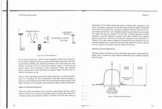
The use of the radio spectrum can be divided into licensed and unlicensed fre-
quency bands. Licensed frequency bands require that the user (or service
provider) apply for the right to transmit radio energy. Unlicensed frequency
bands allow users (or service providers) to communicate without applying for a
license. Unlicensed radio transmission must conform, however, to pre-estab-
lished regulations that specify the frequency bands and amount of radio energy
that can be used. Unlicensed users typically 'have very limited (or none at all)
rights when they experience radio interference.](https://image.slidesharecdn.com/29784614-3g-wireless-demystified-120918184903-phpapp01/85/3-g-wireless-demystified-16-320.jpg)
![-
3G Wireless Demystified Chapter 1
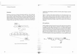
The ability to transmit information through the air is consideid a natural wireless is considered an integration of cellular, wireless office, cordless, ~vire-
resource and is, therefore, regulated by national government agencies. less local area network and satellite systems with the addition of advanced infor-
Frequency bands that are used by wireless communication devices are assigned mation services. Regardless of the type of system, wireless systems all use radio
by the International Telecommunications Union (ITU). The ITU is part of the channels to communicate with wireless telephones.
United Nations. Although the ITU coordinates the general frequency assign-
ments, it is up to the department of communication (DOC) in each country to
Cellular and PCSIPCN
regulate and assign the specific frequency bands to individual companies or
users.
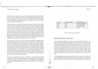
The cellular concept originated at Bell Laboratories in 1947 [2]; the first auto-
Each country has its own regulatory agency. In the United States, Federal matic cellular system started operation in Japan in 1979; and the first cellular
Communications Commission (FCC) regulates the use of radio spectrum, while system in the United States started in Chicago in October 1983. All mobile radio
the Department of Communications (DOC) regulates it in Canada. systems use cellular technology, and this includes personal communication ser-
vices (PCS) and personal communications network (PCN) systems. PCSJPCN
systems are names that are used to refer to celIuIar systems that operate at high-
Wireless Systems er frequency bands.
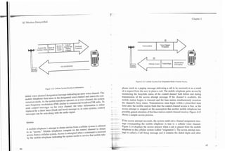
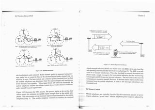
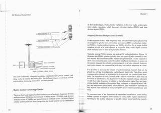
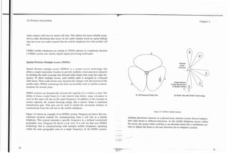
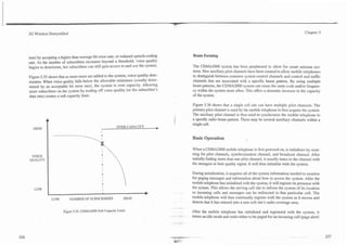
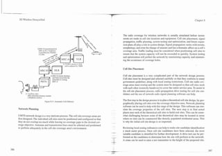
A single cellular system interconnects many small radio coverage areas (called
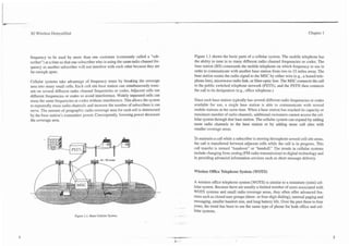
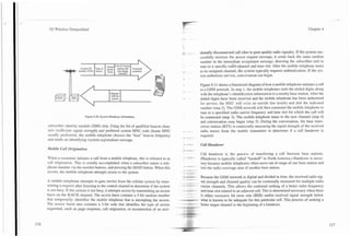
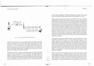
Wireless systems link customers and information services via a wireless com-
"cells") to serve hundreds of square miles. Radio frequencies in cellular systems
munication path o r channel. A typical wireless communications system uses
are reused in distant cells, and telephone calls are automatically switched
mobile or fixed radios that communicate with a fixed radio tower (called a base
between neighboring cell sites when the wireless telephone moves out of range
station),which connects to the public switched telephone network (PSTN) or a
of the serving cell. The wireless telephone is called user equipment (UE) in 3rd
data network (such as the Internet).
generation systems, is called mobile equipment (ME) or mobile station (MS) in
2nd generation systems, and mobile radio in some first generation systems.
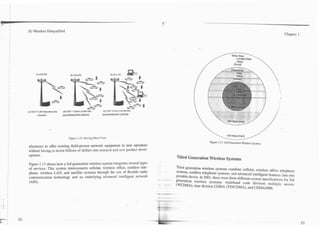
Traditionally, different types of wireless systems have been used for different
types of services. Cellular systems provide radio coverage to a wide area, such
Neighboring cellular systems often allow customers from other cellular systems
as a city, through the use of many radio towers (25 to 500 per city). Wireless
to use their service, a practice called roaming. The basic goals for cellular sys-
office telephone systems (WOTS) typically use 5 to 20 small radio base stations
tems include affordability, nationwide (and possibly global) compatibility, the
to offer radio coverage in small areas such as a school campus or hospital build-
ability to provide efficient service to many customers, and the ability to sen7e
ing. Cordless telephones (often called "residential cordless" or "home cordless")
many types of telephones (fixed,'mobile and portable) at the same time.
usually allow one handset to communicate with a single radio base station with-
in a home. Wireless local area network (WLAN) systems allow computers and
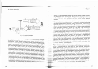
The cellular concept employs a central switching office called a mobile-senrice
workstations to communicate with each other using radio signals to transfer
switching center (MSC) to interconnect the small radio coverage areas into a
high-speed digital information. Satellite systems provide low-speed digital voice
larger system. To maintain a call when the cellular telephone moves to another
and high-speed broadcast services to a large geographic region. Third generation
-- coverage area, the cellular system switches the phone's radio channel frequency
to a frequency in use at an adjacent cell site. The cellular concept also allows a](https://image.slidesharecdn.com/29784614-3g-wireless-demystified-120918184903-phpapp01/85/3-g-wireless-demystified-17-320.jpg)
![-
3G Wireless Demystified
MHz wide bandwidth. To u p p d e 2nd generation IS-95 systems to 3rd genera-
Chapter 2
tion capability, IS-95 radio channels in the base station can be enhanced with
new protocols, and new 3rd generation mobile telephones are required.
References:
First Generation Analog Cellular
1. GSM MoU, www.GSMWorld.com, February 22. 2001.
2. Bell Systems Technical Journal. Vol. 58, No. 1, American Telephone and Telegraph
Company. Murray Hill, NJ, Januan 1979.
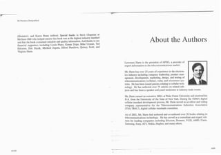
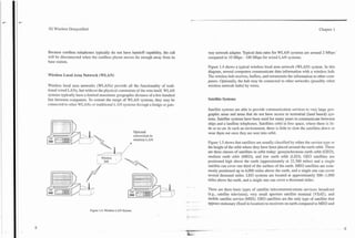
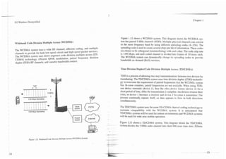
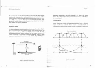
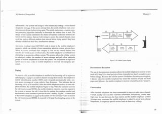
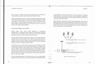
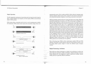
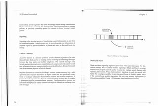
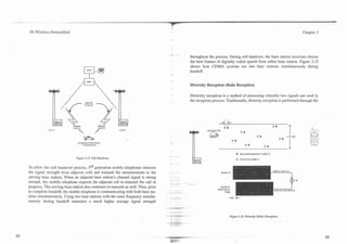
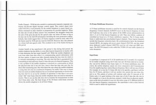
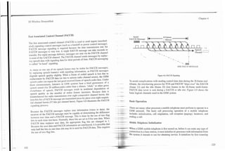
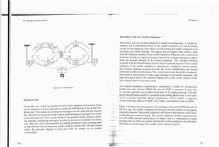
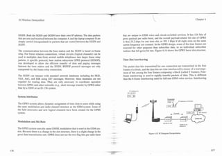
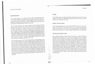
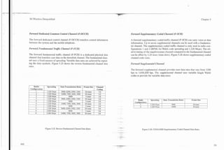
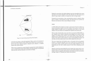
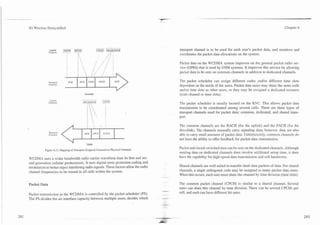
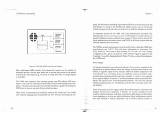
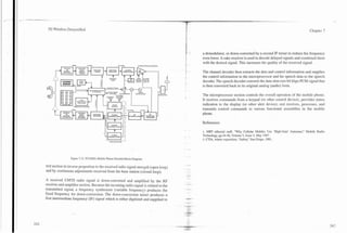
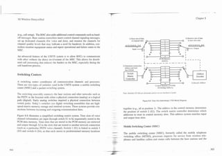
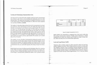
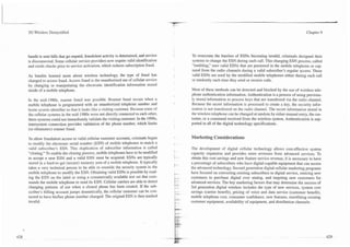
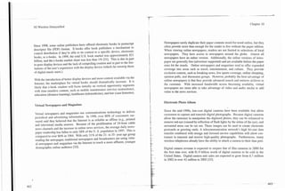
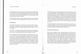
The first generation of cellular systems used analog radio technology. Analog
cellular systems consist of three basic elements: a mobile telephone (mobile
radio), cell sites, and a mobile switching center (MSC). Figure 2.1 shows a basic
cellular system in which a geographic service area such as a city is divided into
smaller radio coverage area cells. A mobile telephone communicates by radio
signals to the cell site within a radio coverage area. The cell site's base station
(BS) converts these radio signals for transfer to thE MSC via wired (landline) or
wireless (microwave) communications links. The MSC routes the call to anoth-
er mobile telephone in the system or the appropriate landline facility. These three
elements are integrated to form a ubiquitous coverage radio system that can con-
nect to the public switched telephone network (PSTN).
History
Nippon Telephone and Telegraph (NTT)in Tokyo started the first commercial
analog cellular system on December, 1979 [I]. In 1981, the commercial Nordic
- -
Mobile Telephone (NMT) system was started in the Nordic countries [2].
Although there was an Advanced Mobile Phone Service (AMPS) test system
-
-.
operating in 1979, the first commercial AMPS system was not introduced in the
United States until 1983. By 1985, a commercial TACS system began in the
-
-- -](https://image.slidesharecdn.com/29784614-3g-wireless-demystified-120918184903-phpapp01/85/3-g-wireless-demystified-30-320.jpg)
![r
3G Wireless Demystified Chapter 2
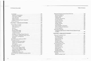
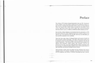
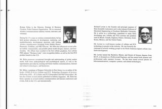
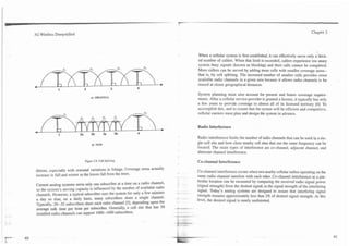
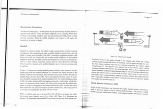
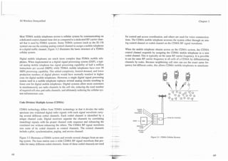
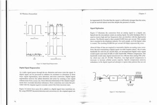
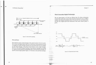
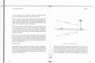
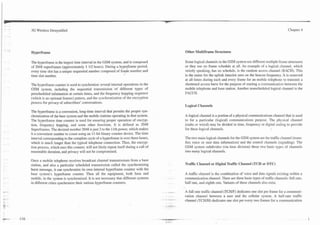
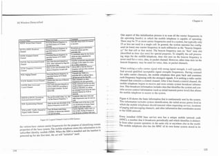
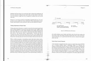
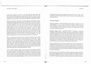
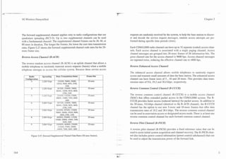
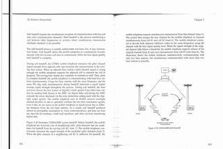
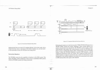
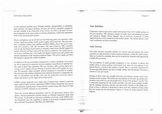
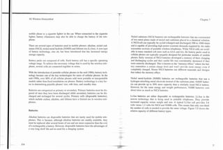
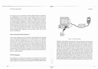
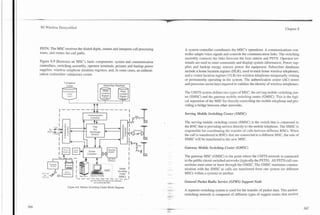
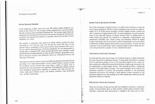
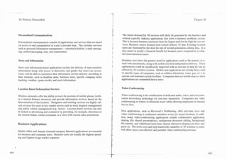
allow the subscriber to communicate commands to the transceiver. The antenna
assembly couples RF energy between the electronics within the mobile tele-
Base Station
phone and the outside "air" for transmission and reception.
0Radio Coverage Area
Analog mobile cellular telephones have many industry names. These names
sometimes vary by the type of cellular radio. Handheld cellular radios are often
referred to as "portables." Cellular radios that are installed in cars are typically
called "mobiles." Cellular radios mounted in bags are often called "bag phones."
In most cases, these three types and sizes also correspond to three distinct max-
imum power levels: 600 milliwatts, 1.6 watts, and 3 watts, or classes I, 11, and
nr.
To make each mobile telephone unique, several types of information are stored
into its internal memory. This internal memory is called a number assignment
- - - - - - - - - - - I@E!l!TEK I '
r-- -
t I
I I
I*)(;IC
Figure 2.1. Basic Cellular System, ASSEMBLY
United Kingdom [3]. Since their introduction, these first generation analog cel- I
I ANTESNA ASSELIBLY
lular technologies have evolved to provide higher system capacity and advanced I
features.
--- - - - - - - XEEL!1EB_l 'I
_ _ _ _ _ _ _ _ _ _ _ _ _ _ _ _ I
TRNSCEI'ER UNIT
Mobile Telephone
A mobile telephone (commonly called a mobile station) contains a radio trans-
ceiver, user interface, and antenna assembly (see Figure 2.2) in one physical
package. The radio transceiver converts audio to radio frequency (RF) signals
Figure 2.2. Mobile Telephone Block Diagram.
and RF signals into audio. A user interface provides the display and keypad that](https://image.slidesharecdn.com/29784614-3g-wireless-demystified-120918184903-phpapp01/85/3-g-wireless-demystified-31-320.jpg)
![-- -.-
't
3G Wireless Demystified Chapter 2
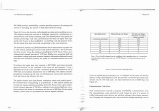
tems low. The customer demand for the few available channels was very high.
For example, in 1976, New York City had only 12 radio channels to support 545
subscribers (not all customers use 2 r2dio channel at the same time) and a two-
year long waiting list of typically 3,700 [4].
TOP VIEW
To increase the number of radio channels in where the frequency spectrum allo-
cation is limited, cellular providers must reuse frequencies. Because the rndio
channel signal strength decreases exponentially with distance, subscribers who
are far enough apart can use the same radio channel frequency without interfer-
ence (see Figure 2.6).
To minimize interference in this way, cellular system planners position the cell
sites that use the same radio channel frequency far away from each other. The
distances between sites are initially planned by general RF propagation rules, but
it is difficult to account for enough propagation factors to precisely position the
towers, so the cell site position and power levels are usually adjusted later.
The acceptable distance between cell sites that use the same channel frequencies a) OLD OMNI b) S E W SECTORIZED
are determined by the distance to radius ( D R ) ratio. The D/R ratio is the ratio of
the distance (D) between cells using the same radio frequency to the radius (R)
of the cells. In analog systems, a typical D/R ratio is 4.6: a channel used in a cell
with a 1 mile radius would not interfere with the same channel being reused at a
Figure 2.7. Cell Site Sectorization.
cell 1.6 miles away.
frequency reuse. Directional antennas can be used to sector a cell in to wedges
so that only a portion of the cell area (e.g., 113, or 120 degrees) is used for a sin-
Capacity Expansion
gle radio channel. Such sectoring reduces interference with the other cells in the
area. Figure 2.7 shows cells that are sectored into three 120-degree sectors.
As cellular systems mature, they must serve more subscribers, by either adding
more radio channels in a cell or adding new cells. To add radio channels, cellu- Another technique, called cell splitting, helps to expand capacity gradually. The
lar systems use several techniques in addition to strategically locating cell sites radio coverage area of a cell site is split by adjusting the power level andlor using
that use the same frequencies. Directional antennas and underlayloverlay trans- reduced antenna height to cover a reduced area (see Figure 2.8). Reducing the
mit patterns improve signal quality by focusing radio signals into one area and radio coverage area of a cell site by changing the RF boundaries of a cell site has
reducing the interference to other areas. The reduced interference allows more the same effect as placing cells farther apart, and allows new cell sites to be
added. However, the boundaries of a cell site vary with the terrain and land con-](https://image.slidesharecdn.com/29784614-3g-wireless-demystified-120918184903-phpapp01/85/3-g-wireless-demystified-35-320.jpg)
![I
I 3G Wireless Demystified Chapter 2
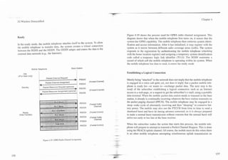
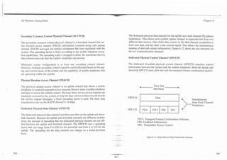
Interleaved Radio Channels
Voice Channel
Because a majority of the radio energy is in the center of the band, some cellu-
lar systems allow radio channels to be interleaved (offset) at fi channel band-
width (e.g., 12.5 kHz offset in a 25 kHz channel) to allow radio channel spacing
to be as close as possible. Since a goal of the cellular system is to reuse as many
radio channel frequencies as possible, placing more radio channels in each cell O ~ c c e s System
s
site increases the capacity of the cellular system. By careful frequency planning,
the use of interleaved radio channels can increase system capacity by more than
100% [ 7 ] .
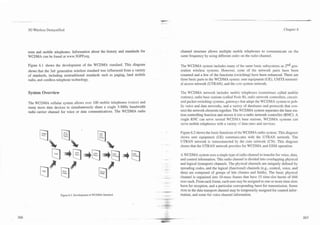
Basic Cellular Operation
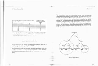
In early mobile radio systems, a mobile telephone scanned the limited number of
available channels until it found an unused one that allowed it to initiate a call.
Because analog cellular systems often have hundreds of radio channels, a mobile
telephone cannot scan them all in a reasonable amount of time. To quickly direct
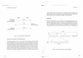
Figure 2.1 1. Control Channels and Voice Channels.
a mobile telephone to an available channel, some of the available radio channels
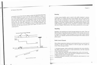
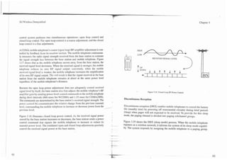
are dedicated as control channels. Most cellular systems use two different types
of radio channels: control channels and voice channels. Control channels carry
only digital messages and signals that allow the mobile telephone to retrieve sys- When a mobile telephone is first powered on, it initializes itself by scanning a
tem control information and compete for access. Control channels never carry predetermined set of contml channels and then tuning to the strongest one.
voice (in the AMPS system). Voice channels are primarily used to transfer voice Figure 2.12 shows that during this initialization mode, it retrieves system identi-
information, but also send and receive some digital control messages, and cer- fication and setup information.
tain super-audible tones used for call processing control. Figure 2.11 shows
some channels that are dedicated as control channels to coordinate access to After the mobile telephone initializes, it enters the idle mode where it waits to be
the cellular system. After the access to a cellular system has been authorized, the paged for an incoming call and continually senses the keypad to determine if the
control channel sends out a channel assignment message that commands the user has initiated (dialed) a call (access). When a call begins to be received or
mobile telephone to tune (change frequency) to a voice channel (a different radio initiated, the mobile telephone enters system access mode to try to access the
channel). System via a control channel. When it gains access. the contml channel sends an](https://image.slidesharecdn.com/29784614-3g-wireless-demystified-120918184903-phpapp01/85/3-g-wireless-demystified-38-320.jpg)
![Chapter 2
3G Wireless Demystified
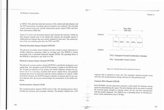
the call in progress. The incorrect supervisory tone alerts the mobile telephone
The supervisoq tone provides a reliable transdssion path between the mobile to mute the audio from the interfering signal.
telephone and base station, and is transmitted along with the voice to indicate a
closed loop. The tone functions are much like the cumnt/voltage functions used Retransmission of the supervisory tone can also be used to locate the mobile
in landline telephone systems to indicate that a phone is off the hookb]. The telephone's position. An approximate propagation time can be calculated by
supervisory tone may be one of the several frequencies (around 6 kHz for comparing the phase relationship between the transmitted and received supervi-
AMPSITACS and 4 Wz for W I T ) , and this tone is different for nearby cell sites. sory tones. This propagation time is correlated to the distance from the base sta-
If the supervisory tone is intempted for l o n g r than about 5 seconds, the call is tion. However, multipath propagation (radio signal reflections) makes this loca-
terminated. In some systems such as NAMPS or NTACS, the SAT tone is tion feature inaccurate and only marginally useful [lo]. Only the retransmission
replaced with a digital supefiisory signal, which is sent out of band on a sub- of the supervisory tone as a pilot tone is critical to operation.
hand dieital signaling channel. Figure 2.19 shows how a supervisory tone is
-
~
w -
transponded back to the base station. A signaling tone (ST) is used in some systems to indicate a call status change. It
confirms messages sent from the base station and is similar to a landline phone
The use of different supervisory tone frequencies in adjacent cell sites is also status change of going on or off hook [ l 11. Similar to the digital supervisory sig-
used to mute the audio when co-channel interference occurs. Interfering signals nal, in some systems such as NAMPS or NTACS, the signaling tone is replaced
have a different supervisory frequency than the one designated by the system for with a digital signaling tone, which is sent out of band on a sub-band digital sig-
naling channel.
Touch-Tone.(registered trademark of AT&T) signals may be sent over the voice
VOICE channel. DTMF signals are used to retrieve answering machine messages, direct
'A
ST automated PBX systems to extensions, and a variety of other control functions.
4
Bellcore specifies frequency, amplitude, and minimum tone duration for recog-
7 nition of DTMF tones [12]. The voice channel can transmit DTMF tones, but
varying channel conditions can alter the expected results. In poor radio condi-
tions and a fading environment, the radio path may be briefly interrupted, some-
2 times sending a multiple of digits when a key was depressed only once.
VOICE Blank-and-Burst Messages
$AX
i -- When signaling data is about to be sent on the voice channel, audio FM signals
- - are inhibited and replaced with digital messages. This interruption of the voice
signal is normally so short (less than 114 second) that the mobile telephone user
Figure 2.19. Transponding SAT.](https://image.slidesharecdn.com/29784614-3g-wireless-demystified-120918184903-phpapp01/85/3-g-wireless-demystified-45-320.jpg)
![3G Wireless Demystified Chapter 3
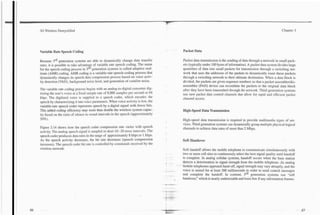
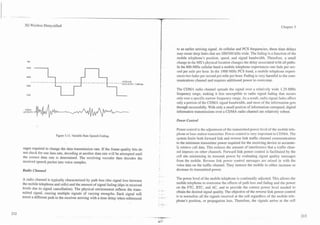
characteristic of the human voice. The result is a digital signal that represents the
voice audio frequency spectrum content, not a waveform.
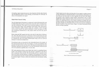
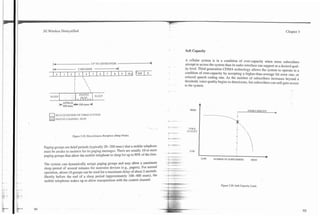
Low bit-rate speech coders analyze the 64 kbps digitized speech signal and char- 64,000 bits 2,000 - 8,000 bits
per second per second
acterizes the signal into spectrum, pitch, volume, and other parameters. Figure
3.8 illustrates the basic speech compression process. The speech coder examines
10--20 millisecond time windows of the speech signal. Mathematical analysis of From Analog Predictive
this sample of the waveform (which contains many cycles of the speech wave- To Digital Converter Coding TOChannel Coder
form) produces several numbers called the prediction coefficients. These num-
bers are used in a mathematical process called predictive coding. When a pulse
(in digital numerical representation form) is put into this predictive coder as
input, the resulting output is a waveform (also represented in digital form) that
has a similar audio frequency spectrum to the original speech. As the speech
coder characterizes the input signal, it looks up codes in a code book table that
represent various pulse patterns (rather than just a single pulse) to chose the pat-
~ l l o l l ~ l l l ~
tern that comes closest to matching the output of the predictive coder to the orig-
inal time window voice signal. The coding process requires a large number of Code Book
mathematical calculations because the predictive coder output must be recalcu-
lated many times at a rate faster than real time in order to find the best match.
The coder system then sends the caefficients used in the predictive coder and the Figure 3.8. Speech Coding.
entry from the code book table to a decoder at the other end of the radio link. The
compression process may be fixed or variable. When variable, the compression as a human voice, the background noise is not in its code book. The speech coder
may vary from 4: 1 to 64: 1 depending on speech activity. will find the code that comes closest to the sound that matches the combined
. -
background noise and the human voice. The result is usually distortion.
High bit-rate speech coders [(small amount of compression, such as 32 kbps
adaptive differential pulse code modulation (ADPCM)] typically convert the As a general rule, with the same amount of speech coding analysis, the fewer bits
waveform into a representative digital signal. Low bit-rate speech coders [high used to characterize the waveform, the lower the quality the speech-signal. If the
amount of compression such as VSELP or Qualcom code-excited linear predic- complexity (signal processing) of the speech coder can be increased, it is possi-
tion (QCELP)] analyze the waveform for key characteristics. In essence, low bit- ble to get improved voice quality with fewer bits. The speech coders used in the
rate speech coders model the source of the waveform while high bit-rate ones digital cellular phones typically require 8 MIPS to process the voice signal. It has
characterize the actual waveform. This process makes low bit-rate speech coders - been estimated that it will take four times the amount of processing to reduce the
more susceptible to distortion from background noise and bit errors, poorer voice number of bits by additional factor of two.
quality from a poor coding process model, and echoes from the speech coder /
processing time. t- -..- Voice digitization and speech coding take processing time. Typically, speech
- _ .. frames are digitized every 10--20 msec and input to the speech coder. The digi-
When there is a significant amount of background noise, distortion in the coding ...- --*...
process occurs. Because the speech coder attempts to characterize the waveform](https://image.slidesharecdn.com/29784614-3g-wireless-demystified-120918184903-phpapp01/85/3-g-wireless-demystified-54-320.jpg)
![3G Wireless Demystified
needs to have minimal round trip delay. Delay up to a few seconds may be
Chapter 4
acceptable. It also requires interactive class to have high reliability of data trans-
mission (data files error free).
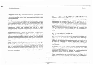
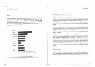
Background Class GPRS and EDGE (2.5 Generation)
Background services do not require immediate actions by the customer.
Background class is used for email downloads or software updates that may
occur during voice conversation. Background class is tolerant to delays of sev-
eral seconds or even longer, and low data transfer rates may be acceptable.
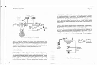
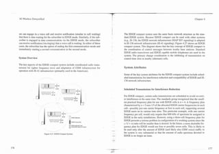
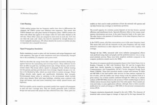
To meet the growing needs for efficient new wireless services without the
upgrading of systems to 3rd generation technology, two new standards were cre-
ated: general packet radio service (GPRS) and enhanced data for global evolu-
tion (EDGE). GPRS and EDGE use enhanced GSM technology to provide for
higher data transfer rates than are normally available in GSM systems. The com-
bination of GPRS and EDGE is referred to as enhanced GPRS (EGPRS).
EGPRS comprises the 43 series of specifications managed by the 3rd generation
partnership project (3GPP) [I]
EDGE and GPRS technologies are commonly called 2.5G because they offer
capabilities that are above the present day 2G digital cellular systems (greater
than 14 kbps) but do not achieve the performance of 3G systems (less than 2
Mbps). Subscriber data transfer rates possible in 2.5G GPRS can achieve over
170 kbps and EDGE technology may exceed 384 kbps if the quality of the radio
transmission link is good.
Two-and-a-half generation technology was developed partly to fill what some
industry people see as a hole in the price-performance range of the overall 3G
plan. For various reasons, some observers of the industry believe that the two
most prominent service offerings of this 2.5G strategy may meet the price-per-
, - formance needs of most subscribers sufficiently well that 2.5 G may effectively
compete with 3G systems.
.-](https://image.slidesharecdn.com/29784614-3g-wireless-demystified-120918184903-phpapp01/85/3-g-wireless-demystified-65-320.jpg)
![IC
. .
3G Wireless Demystified Chapter 4
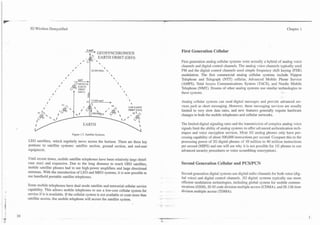
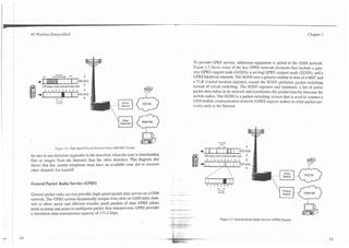
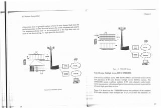
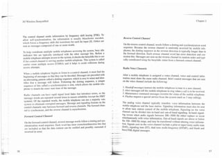
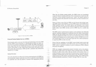
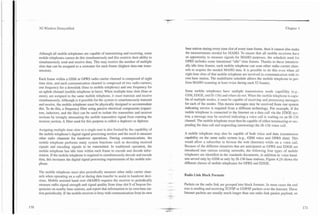
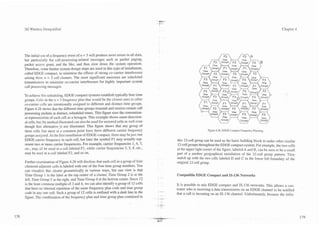
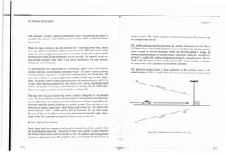
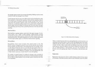
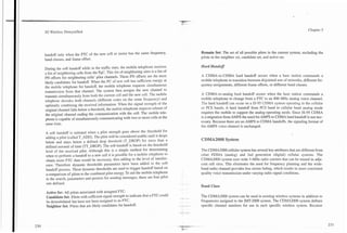
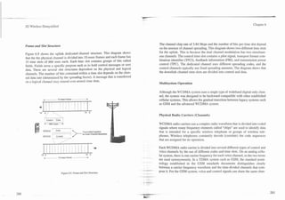
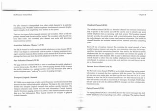
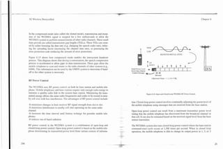
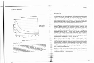
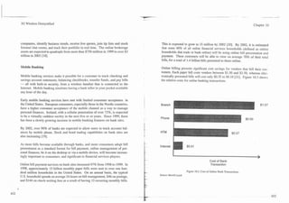
GPRS and EDGE systems are compatible with GSM networks. Mobile tele- such as data transmission and short messaging (phase 2), and progressed to offer
phones that are that have GPRS or EDGE capability can easily provide GSM GPRS packet transmission service (phase 2+). A competing TDMA digital radio
voice service. To upgrade GSM systems t9 offer GPRS and EDGE service, pack- system that was originally developed in North America has also evolved from
et-switching hardware is added to an existing GSM network. On the radio side, basic digital voice services (IS-54), to enhanced digital services such as short
little or no hardware changes are needed. Of course, new mobiIe telephones (or messaging (IS-136), to a new high-speed data transmission system. The combi-
upgraded models) that are capable of GPRS or EDGE data service are also nation of GSM radio channel structure (200 kHz), packet switching offered by
required for the subscribers that want to use GPRS or EDGE services. GPRS, and efficient phase modulation (8QPSK) has been combined to produce
the EDGE system.
In a celI with a base station that supports both GSM voice and GPRS and/or
EDGE, a subscriber with a suitable multimode mobile telephone can simultane- GPRS and EDGE can coexist on a standard GSM system. Both GPRS and
ously engage in a GSM voice conversation while transfemng data packets via EDGE provide packet data transmission across the radio link between base sta-
GPRS and/or EDGE. This is called dual transmission mode ( D m ) . tion and mobile telephone and also via packet switching infrastructure within the
network facilities. GPRS and EDGE permit the mobile subscriber to communi-
History
GPRS and EDGE evolved from the GSM and IS-136 TDMA technology. The
+
GPRS system uses the same radio channel structure as the GSLI system while
the EDGE system enhances the GSM radio channel with improed radio chan-
nel modulation technology. EDGE systems are sometimes called GSM 84 to
indicate that the EDGE system is capable of the UMTS outdoor trans ission
requirement of 384 kbps.
GPRS belongs to the phase 2+ of the GSM standard. Phase 2+ features (pro-
nounced "two plus") are enhancements to the second phase of GSM technology.
GPRS was developed to provide high-speed packet data access for the GSM net-
work. EDGE evolved from contributions of the universal wireless consortium
136 (UWC-136) for more efficient outdoor systems (wide area mobility). As a
result, the standards for GPRS and EDGE are substantially the same as the - --
UWC-136-HS-Outdoor standard for data evolution of IS-136 [2]
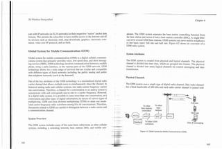
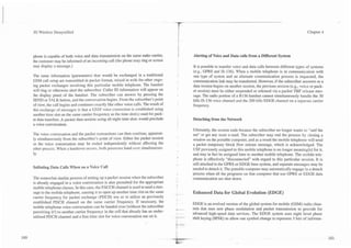
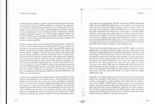
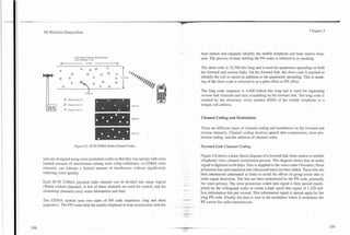
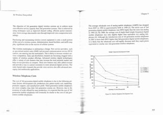
Figure 4.1 shows the evolution of GPRS and EDGE standards. This diagram
shows that the GSM system that was originally developed in Europe has evolved -
- -- Figure 4.1. Evolut~on GPRS and EDGE Standards.
of
from basic digital voice services (phase I), through enhanced digital services
- .](https://image.slidesharecdn.com/29784614-3g-wireless-demystified-120918184903-phpapp01/85/3-g-wireless-demystified-66-320.jpg)
![-.
3G Wireless Demystified Chapter 4
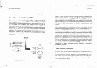
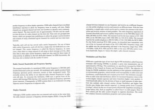
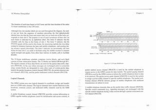
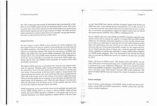
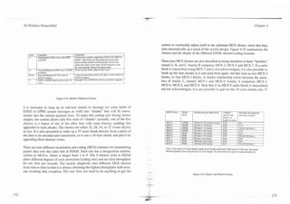
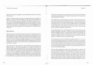
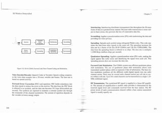
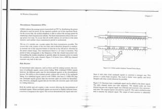
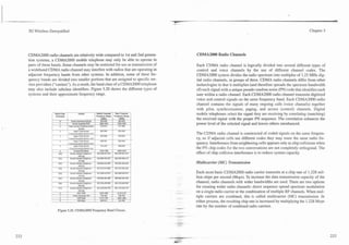
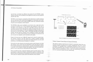
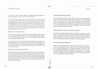
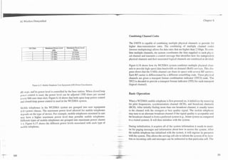
At the end of the burst is a guard .period. A guard period is included to allow a
buffer time period to ensure transmitted bursts do not overlap as perceived at the Power profile ag bits (normal burst only) indic
base receiver with radio bursts received from other mobile stations due to their f fast associated channel (FACC
b
distance from the base station (guard periods). During the guard period, the
Normal and Dummy Burst- RACCH) in both directions
mobile telephone transmitter is off. Figure 4.5 shows the normal burst field
structure. Normal b(<rlInformation IFI Training Bits ]FI Information l ~ ( 2 ,GP
1 I
/"
,- Bits 3 57 1 26 1 57 3 8.25
Most of the radio transmission bursts used in GPRS and EDGE involve a normal Synchronization TITI Information I LongTraining Sequence 1 Information IT^ GP'
burst. The 8.25 symbol "silent" time interval is known as the guard period, since Bits 3 39 64 39 3 8.25
Frequency
it helps to prevents time overlap (and thus mutual interference) of received sig- correction T(1 binary bits all zero in F burst ~ 1 2 GP
1
nals from two different mobile transmitters operating in consecutive time slots Bits 3 142 3 8.25
when their radio signals arrive at the base receiver. When two mobile transmit- T(l) -Tail Bits (Ramp) -
F Flag Bits
ters using two consecutive time slots are very different in their distance from the -
Information User or message data T(2) -Tail Bits
base station, the radio burst from the more distant transmitter will arrive at the
-
Training Synchronization & training -
GP Guard Period
base receiver later than the radio burst from the nearby transmitter. This is due to
the delay of approximately 3 microseconds per km (5 microsec per mile) from Figure 4.5. Normal Burst Bit Field Structures.
travel of the radio wave through space. GSM, GMSK, and EDGE mobile radios
can be commanded by the base station to advance the time of a transmitted radio design and structure of the mobile telephone , since there is no need for a fre-
burst. In this way. the signal from a distant mobile transmitter is properly time quency filter to prevent the transmit signal from "leaking" back into the receiv-
aligned to fall in the correct time slot at the base receiver. The 8.25 symbol guard er.
time allows for minor inaccuracies in the advance timing adjustment, or for the
presence of some delayed radio power that reflects off of objects in the cell (mul-
tipath transmission) and thus arrives later than the expected delay time. Random Access (Shortened Burst)
The numbering identification of the eight time slots, from 0 to 7, used for pur- Random access bursts are used when a mobile station attempts to access the cel-
poses of assignment of particular time slots to particular mobile subscribers dur- lular system. Because the distance from a base station radio tower is not known
ing an individual communication, is the same in GPRS and EDGE as for GSM when a mobile telephone requests access, the radio transmission travel time from
voice or circuit-switched data systems. The numbering identification is assigned the mobile telephone to the base station can be excessive. This causes normal
to the base and mobile transmitter time slots with a physical difference of three bursts to overlap in time with bursts that are received from other nearby mobile
time slots. A particular time slot interval is labeled time slot 4 at the base trans- telephones. To overcome this challenge, initial bursts from mobile telephones are
mitter, and the same time interval is labeled time slot 1 at the mobile transmitter. shorter than normal bursts. A shortened burst (access burst) is only 88 bits in
In this way, the mobile telephone assigned to use time slot 1 'does not physical- duration. Most of these bits are used for preset binary synchronizing and train-
ly transmit and receive at the same time. This also permits simplification of the ing bit patterns. The primary purpose of the access burst is to get the attention of
the base system to indicate an mobile telephone is requesting service. After the](https://image.slidesharecdn.com/29784614-3g-wireless-demystified-120918184903-phpapp01/85/3-g-wireless-demystified-71-320.jpg)
![v
.--. -- -. -
-
3G ii5reless Demystificd Chapter 5
posal for the 2nd generation of mobile communications system. Unfortunately, the CDMA system into the marketplace. IS-95 CDMA systems rapidly gained
it did not meet with immediate approval by the standards committee since it had market share through the key benefits of spread spectrum technology.
just resolved a two-year debate between TDMA and FDMA and was not eager Information about the history and standards for WCDMA can be found at
to consider another access technology. To prove the advantages of CDMA tech- www.3GPP2.org.
nology. CDMA cellular service began testing in the United States in San Diego,
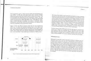
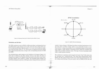
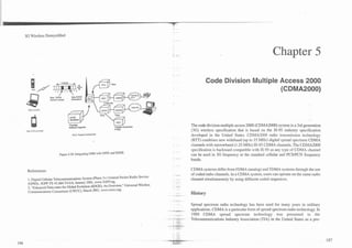
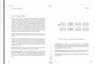
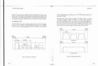
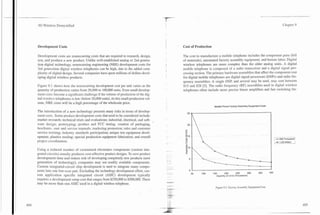
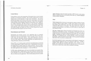
California, during 1991. As a result of continued persistence of CDMA propo- Figure 5.1 shows the development of t h e ' c ~ ~ ~ 2 standard. This diagram
000
nents. in 1995, IS-95 CDMA commercial service began in Hong Kong, and a 1.9 shows that the CDMA2000 wireless standard was influenced by a variety of
-GHz all-digital system started service in the United States in October 1996. standards including Advanced Mobile Phone System (AMPS), IS-54 TDMA, IS-
136 TDMA, and GSM. The IS-95 CDMA standard also evolved through revi-
The development of CDMA was partially inspired by an attempt to satisfy the sions A and B. Revision B provides for higher data transmission rates. The
goals of the Cellular Telecommunications Industry Association (CTIA) user per- CDMA2000 standard is divided into two phases. Phase 1 enhances the 1.25
formance requirements (UPR) objectives for the next generation of cellular tech- MHz radio channel (called IXRTT) to provide for higher data rates. Phase 2
nolog: particularly the goal of increasing capacity to 10 times that of analog cel-
lular technology. In response to these objectives, radio specifications were creat-
ed that CDMA proponents claimed would satisfy the requirements. A proprietary
specification was presented by Qualcomm to the Telecommunications Industry
Association (TIA) which modified and accepted it as the IS-95 CDMA specifi-
cation.
The CDMA2000 system was standardized by the Third Generation Partnership
Project 2 (3GPP2). The 3GPP2 group was formed to develop the necessary
extensions to the IS-95 CDMA standard to satisfy the IMT-2000 system require-
ments. X key factor for the development of CDMA2000 system was to allow the
upgrade of existing IS-95 CDMA systems and to use the IS-41 intersystem sig-
naling system (developed for the Americas). It is expected that the CDMA sys-
tem will also be compatible with the global system for mobile (GSM) commu-
nications system's mobile applications part (MAP) infrastructure. In October
2000, the first commercial third generation wireless system was started by SK
Telecom in Korea [I].
In 2001, IS-95 CDMA had over 11.8% global market share with more than 84.6
million subscribers [2]. This market share alas achieved despite the late entry of
Figure 5.1. Development of CDMA2000 Standard.](https://image.slidesharecdn.com/29784614-3g-wireless-demystified-120918184903-phpapp01/85/3-g-wireless-demystified-110-320.jpg)
![3G Wireless Demystified Chapter 5
two-way communications on systems that do not have two available frequency
bands [3]. Many of the attributes of the FDDlCDMA2000 system were main-
tained including the 1.25-MHz multiple radio channel width and base 1.228-
Mcps chip rate to easily allow inter-operation with the FDDlCDMA2000 sys-
tem.
The TDDICDMA system divides the radio channel into 20 msec or 5 msec
frames, and each frame is divided into 1.25-msec time slots. The time slots are
assigned at different times for transmit and receive to allow two-way communi-
cations between the mobile telephone and the system.
Figure 5.4 shows how the TDDlCDMA2000 system operates.
TDDlCDMA2000 full duplex radio channels are divided by code sequences and
time periods. TDDICDMA mobile telephones transmit and receive on one same
frequency. Separate time slots are assigned for transmit and receive, and multi-
ple time slots may be assigned to allow different data transmission rates for the
downlink and uplink. During usual operation, the mobile telephone receives a
burst of data, waits until its assigned transmit time slot, and transmits a burst on
the same frequency. This process is continually repeated, allowing data to steadi-
ly flow in both directions.
Figure 5.4. 'Iime Division Duplex (TDD) CDMA2000 System.
A key challenge for TDD operation is the added requirement of guard times to
ensure bursts of data do not overlap. For mobile telephones that are used close
to the base station, the amount (percentage) of guard time allocated to transmis- The IS-95 CDMA (usually refeired to as CDMA or IS-95) system uses two radio
sion bursts is small. However, as the distance from the cell site becomes larger, channels: one for the downlink (base to mobile telephone) and one for the uplink
the amount of required guard time for each time slot becomes larger. This limits (mobile telephone to base). Each of the radio channels is divided into 20 msec
the use of TDD to operation of within 7 km of the base station [4]. frames, and each frame is divided into 15 time slots (1.25 msec each).
Although the IS-95 CDMA system uses a single type of digital radio carrier,
IS-95 CDMA System there are several types of CDMA (coded) channels. These include a reference
channel identifier (pilot), timing reference (synchronization), an alerting channel
Code division multiple access is a form of spread spectrum communications (paging), channel assignment coordination (access) and channels that transfer
user data such as voice (traffic channels).
which allows multiple users to share the same frequency band by spreading the
information signal (audio or data) for each user over a wide frequency band-
width.](https://image.slidesharecdn.com/29784614-3g-wireless-demystified-120918184903-phpapp01/85/3-g-wireless-demystified-113-320.jpg)
![3G Wireless Demystified Chapter 5
Key system attributes for the IS-95 CDMA system include increased frequency There are 64 different Walsh codes used in the IS-95 CDMA system, each hav-
reuse, efficient variable rate speech compression, enhanced RF power control, ing a fixed length of 64 bits. On the forward link, Walsh codes are used to sepa-
lower average transmit power, ability to simultaneously receive and combine rate the channels. The reverse link channel generation uses the Walsh code for
several signals to increase service reliability, seamless handoff, extended battery orthogonal modulation, also known as orthogonal signaling. Orthogonal
life (power saving), and advanced information service features. describes the property of the code where the addition of each does not create
interference to other codes. However, in a multipath environment, perfect
orthogonality is difficult to achieve.
Spreading (Walsh) Codes in IS-95 CDMA
Figure 5.5 shows how CDMA channels share each radio channel. Digital signals
The spread spectrum encoding system in IS-95 CDMA systems use orthogonal are coded to produce multiple chips (radio energy) for each bit of infonnation to
codes, also referred to as a Walsh code (WC). Orthogonal coding is a system of be transmitted. .S "chip" is a name for one of the bits in the PN bit sequence that
spreading codes that have no relationship to each other. The system also com- is generated at a higher bit rate than the data rate to be coded. The receiver has
bines these orthogonal codes sith two pseudorandom noise (PN) sequences for an internal chip generator that can produce exactly the same PN chip sequence
each communication channel. There are different codes used for different types as the one used for encoding at the transmitter. The time delayof this chip gen-
of channels. The overhead channels (control channels) have designated codes to erator i n the receiver is adjustable to allow for the time that the radio signal
be used ~shile traffic channels codes are selected at the time the transmission or requires to tralrel from the transmitter to the receiver. The receiver shifts the PN
when a call is originated. chip pattern in time until it matches the coded pattern. The particular chip pat- -
tern is illustrated symbolically by a combination of pictures such as circles,
The IS-95 CDMA system uses fixed length orthogonal codes (Walsh codes) to squares, and diamonds in Figure 5.5. Chips on the forward link are selected to
uniquely identify each physical channel. This allows a 1-25-MHz CDMA radio collide only infrequently with chips from other users. A chip collision occurs
channel to have 64 unique physical communication channels. Because each
- - when the binary sequence of a chip pattern (such as 01 1010111000) matches that
physical channel experiences interference from nearby transmitting cell sites and of another chip pattern for a short interval of time. When two chip-sequence pat-
mobile telephones (called interference limited), not all channels are used. As a terns are designed so that there is no complete collision between the two during
result, the combined data throughput for all users cannot usually exceed 192 one data bit interval, this is known as orthogonal coding. The 64 chip or PN pat-
kbps [S]. To obtain a maximum of 64 communication channels for each CDMA terns used in CDlclA are perfectly orthogonal to each other, but each pattern is
radio channel, the average data rate for each user should approximate 3 kbps. If combined with a pattern that is unique to the mobile telephone used for that
the average data rate is higher, less than 64 traffic channels can be used. CDMA channel, and some codes are used in adjacent cells. As a result, chip patterns
systems can vary the data rate for each user dependent on voice activity (variable .-- from many mobile radios may produce short-term collisions on the reverse chan-
rate speech coding), thereby decreasing the average number of bits per user to nel.
about 3.8 kbps [G. Varying the data rate according to user requirement allows
more users to share the radio channel, but with slightly reduced voice quality. -.- Several chips are created for each bit of user information (speech or data), so if
This is called soft capacity limit. .- some of them encounter interference form of code collisions shown in Figure
- 5.5, most of the remaining chips will still be received successfully. CDMA chan-](https://image.slidesharecdn.com/29784614-3g-wireless-demystified-120918184903-phpapp01/85/3-g-wireless-demystified-114-320.jpg)
![-.-- .-
d'-
Chapter 5
3G Wireless Demystified
interference at a mobile. To improve this process, the open loop power control
algorithm was modified to consider the strength of the serving pilot.
Fast Closed Loop
Because the forward and reverse link channels fade differently a fast closed loop
power control mechanism is employed to help overcome the fades not apparent
.IGH
LOW H RECEIVED SIGNAL LEVEL
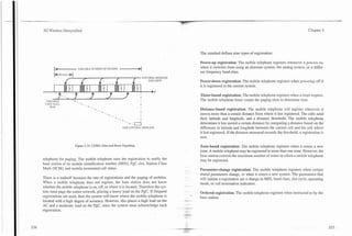
- to the mobile telephone. The base station then fine-tunes the mobile's transmit
power by sending power control commands to the mobile telephone during each
1.25-msec time interval. The command is a single bit sent on a power control nun
subchannel on the FTC. The location of the power control bit within each 1.25- 4 DOWN t t t 4
rnrec time interval is randomly selected using the PN long code. This command
adjusts the transmit power of the mobile telephone in 1-dB steps. The adjustment +
+
is determined by the received signal strength at the cell. The power control bit It*l
1.25 msec
communicates the relative change from the previous transmit level, commanding
the mobile telephone to increase or decrease power from the previous level. FINE TUNE ADJUSTMENT RANGE +_ 24dB
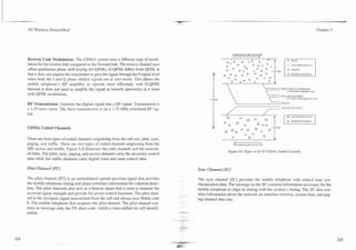
Figure 5.13 illustrates the closed loop power control. As the received signal
strength is too high, the power control bit instructs the mobile telephone to
reduce transmit power. When the received signal strength is lower than desired, Figure 5.13. CDMA Closed Loop RF Power Control.
the power control bit instructs the mobile telephone to increase transmit power.
*
The closed loop adjustment range (relative to the open loop) is 24 dB mini-
mum. The mobile telephone must adjust its output power to within 0.3 dB with-
in 500 msec. The combined open and closed loop adjustments precisely control When the cell enables FTC power control, the mobile telephone reports frame
the received signal strength at the cell. The power control mechanism is analog error rate (FER) statistics. When the mobile telephone senses an increase in
in nature and has a combined dynamic range of 80 dB [7].
received FER, it reports the increase by sending a message or setting a bit. The
message or bit may be sent periodically or when the EER reaches a specified
Forward Link Power Control
threshold. The cell site responds by adjusting its power level that is dedicated to
the mobile telephone on the FTC. The rate of change in transmit power is slow-
In conjunction with the reverse link power control, there is also a forward link
er than used for the mobile telephone. The adjustment can be made once every
power control. The power for each FTC is dynamically controlled in response to 20 msec.
information received from the mobile telephone listening to the FTC. In certain -4.
locations, the link from the cell to mobile telephone may be unusually disadvan-
taged. This requires that the power being transmitted to this mobile telephone be
increased or it will have unacceptable signal quality.](https://image.slidesharecdn.com/29784614-3g-wireless-demystified-120918184903-phpapp01/85/3-g-wireless-demystified-124-320.jpg)
![-- - ---. --
Chapter 5
3G Wireless Demystified
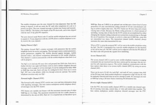
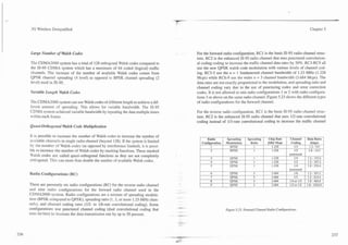
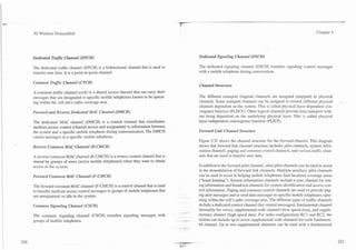
Transmit diversity pilot channel Provides a reference for multiple
transmission sources
Access channel Standard IS-95 C D M 4 access channel
Enhanced access channel Enhanced access channel that allows fast
access for packet data
Reverse common control channel Coordinates extended packet access and
Reverse data transmission
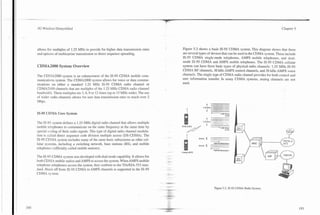
Enhanced Reverse Reverse
Access Access Common Fundamental Fundamental
Channel Control Reverse dedicated control channel Used to send signaling messages to the
Channel Channel Channel
Channel base station during communication
Reverse Reverse Reverse fundamental channel Basic communications channel for voice
Reverse Reverse Supplemental Supplemental communications (max 13.4 kbps) I
Pilot Pilot Code Channel Reverse supplemental coded channel (RCI
Channel ~ d d i t i o n a communication channel(s) for
l
Channel and RC2) voice of data communication (max 14.4 1
Reverse
Dedicated I I kbps). Up to 7 channels can be used with a 1
fundamental channel
Control
Channel
Forward supplemental channel (RC3-RC6) 1
Additional communication channel(s) for
voice or data communication (max 1 0 x x . x ~
kbps). Up to 2 channels can be used with a
Power
Control fundamental channel
Channel
Figure 5.34. CDMA2000 Reverse Channel Types.
Figure 5.33. Reverse Link Channel Structure.
Speech Coding in system capacity by using the lower encoding rates of SMV [9]. The SMV
operational mode can be controlled by the operator or on a dynamic basis. The
SMV standardization process was started at the beginning of 1999 by the
The CDMA2000 system is able to use a new type of speech coder called a selec- 3GPP2. It was completed in February 2001.
table mode vocoder (SMV). SMV is a relatively new technology that provides
quality gains while reducing the average data transmission rate (increased speech
compression) below 4 kbps on IS-95 and CDMA2000 systems while achieving Soft Capacity
excellent voice quality. The 3GPP2, with suppon from the CDG, developed the
.
SMV algorithm. The SMV algorithm allows the continual adjustment of encod-
A cellular system is in a condition of overcapacity when more subscribers
ing rates based on speech characteristics. This helps to ensure the quality of
attempt to access the system than its radio interface can support at a desired qual-
sound to remain high, even in dynamically changing bandwidth conditions. The C
- ity level. CDMA2000 technology allows the system to operate in a condition of
use of SMV allows carriers to trade off small quality losses in speech quality to -
- over capacity (allowing more mobile telephones to communicate with the sys-
gain increased system capacity. Wireless operators may gain up to 75% increase
-](https://image.slidesharecdn.com/29784614-3g-wireless-demystified-120918184903-phpapp01/85/3-g-wireless-demystified-143-320.jpg)
![3G Wireless Demystified Chapter 5
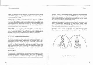
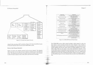
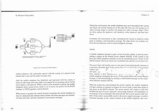
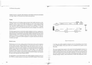
Paging
Paging is the process of sending a page message to the mobile telephone to indi-
@ No Rrsponw 0 SF"
Rcspands cate that a call is to be received. Paging and other messages can be sent to the
Conml
mobile telephone on the paging channel or forward control channel.
Bun. Channel
Assign
Channel
CDMA2000 paging channels and forward control channels can send paging
-
-
I
I
I - messages in groups (called "slotted mode") to aIIow the mobile telephone to
sleep between specific paging groups. The paging channel uses spreading rate 1
L
Random Delay (1.228 Mcps) only [lo]. The primary paging channel is paging channel number
1.
nnrrnpl Access
a .ncmpt
ACCCSI
t
I
Because the CDMA mobile telephone can simultaneously decode more than one
I
I
coded channel, it can monitor multiple paging channels. When the mobile tele-
phone determines that a neighboring cell site has a higher quality paging chan-
nel, it initiates handoff (registers) to the new paging channel.
The basic paging process involves the mobi!e telephone receiving a paging mes-
sage from the system on the paging channel or forward control channel. The
mobile telephone then transmits an access request message on the access chan-
Figure 5.37. CDMA2000 System Access.
nel along with an indication the access request is in response to a paging (or
other types of alert) message. When the system responds, it assigns the mobile
telephone to a specific data channel and conversation may begin.
For enhanced access, there are three modes; basic access, power controlled
access, and reservation access. The basic access procedure includes transmitting
an enhanced access preamble prior to the enhanced access data transmission. Handoff (Handover)
The power controlled access and reservation access procedures include an
enhanced access header message. The reverse pilot channel is transmitted when
Handoff (called handover in other sytsems) is the process of transferring a call
the enhanced access channel is sending header or access data information.
--
between cell sites. The CDMA2000 system enhances the handoff process by
allowing the mobile telephone to transfer calls to different types of systems
including IS-95 CDMA. The CDMA2000 system can perform soft handoff
(same frequency and system) and hard handoff.](https://image.slidesharecdn.com/29784614-3g-wireless-demystified-120918184903-phpapp01/85/3-g-wireless-demystified-146-320.jpg)
![3G Wireless Demystified
Chapter 6
References:
1. www.cdg.org, 14 May 2001.
2. w w w . ~ ~ ~ m o b i l e . c o mDec 2000.
31 ,
3. Telecommunications Industry Association (TIA), "The CDMA2000 ITU-R RTT Candidate
Submission," TR.45.5.4198.06.15.04, 1998, pp. 154-175.
Wideband CDMA (WCDMA)
4. TelecommunicationsIndustry Association (TIA), "The CDMA2000 ITU-R R l T Candidate
Submission," ~~.45.5.4198.06.i5.04, 1998, pp. 154.
5. CDMA maximum data rate for RF channel
6. CDMA average speech coding data rate
7. ANSI J-STD-008; par. 2.1.2.3.1
8. Vijay K. Garg, "IS-95 CDMA and CDMA2000," Prentice Hall, NJ, 2000, pp. 387.
..
9. www.cdg.or~,14 May 2001. Wideband CDMA is system is 3rd generation digital radio system that uses a
10. 3rd Generation Partnership Project 2, "Physical Layer Standard for cdma2000 spread spec- combination of code division multiple access (CDMA) and time division multi-
tmm.systems," 3GPP2 C.SO002-0-2, version 1.13, April 24,2001, pp. 3-1 11. ple access (TDMA) technology to provide for multimedia data services and cost-
effective voice services. WCDMA emerged from a group of companies that
desired to develop a global standard for the 3rd generation mobile communica-
tion system.
History
WCDMA is a digital cellular specification that was initially created to provide a
single global cellular system. WCDMA began development in 1996, and the
first commercial WCDMA digital cellular system was activated in 2001 in Japan.
Because the specification was created by representatives from many countries, it
is accepted as the next generation digital standard by more than 75 countries.
In 2001, GSM was the world leader in digital cellular systems with global mar-
ket share of over 60% [I]. This market share dominance was achieved despite the
GSM system having limited advanced features and less efficient use of radio
spectrum when compared to other digital wireless systems. The GSM systems
gained worldwide market domination through detailed standardization, coopera-
tion between multiple manufacturers, and aggressive (low-cost) pricing of sys-](https://image.slidesharecdn.com/29784614-3g-wireless-demystified-120918184903-phpapp01/85/3-g-wireless-demystified-148-320.jpg)
![--
-
P
3G Wireless Demystified Chapter 6
Speech Coding In the case of several frames that are lost due to errors, previous speech frames
can be repeated or muted. This is called error concealment. The AMR speech
To allow many users to share a single 5-MHz wide radio carrier, voice signals codec can tolerate about 1% frame error rate (FER) [2] without any degradation
are digitally coded and compressed (speech coding) before transmission. of speech quality.
Because the medium of transmission is digital and many different data trans-
mission rates can be allowed, different types of speech coding processes can be The speech-coding process can be combined with a voice activity detector
used. The lower the data transmission rate is (higher speech compression), the (VAD) to allow discontinuous transmission (DTX). When there is no speech
higher the system capacity can be (more users can simultaneously share each activity (e.g., when a user temporarily stops talking to listen to the other user),
radio channel). the speech compression may be temporarily suspended and the transmitter may
be shut off. When this occurs, the talker would not hear any sound from the user
The speech coding in the WCDMA system can use multiple source rates. These and may become concerned that the connection is lost ("are you still there?'). To
include the standard 12.2-kbps GSM enhanced full rate (EFR), 10.2-kbps, 7.95- overcome this challenge, a silence descriptor (SID) frame is periodically sent to
kbps, 7.4-kbps interim standard 641 (IS-641), 6.7-kbps Pacific digital cellular allow for the realistic creation of comfort noise (background noise) at the receiv-
(PDC) EFR, 5.9-kbps, 5.15-kbps, and 4.75-kbps. Other types of speech coders ing end when no voice activity is present.
may be added as advances in speech coding technology are improved.
The selection of the speech coder is determined by the system. The combination Discontinuous Reception (Sleep Mode)
of these different data rates is called adaptive multirate (AMR) speech coding.
By using adaptive speech coding technology, the data transmission rate for each To increase the time until battery recharge of a WCDMA mobile telephone, the
user can be reduced when necessary, thus increasing the capacity of the system system was designed to allow the mobile telephone to power off nonessential cir-
or extending the boundaries of the cell size. cuitry (sleep) during periods when paging messages will not be received. This is
known as discontinuous reception (DRX). To provide for DRX capability, the
The adaptive multirate speech coding that is used in the UMTS system is based paging channel is divided into paging subchannel groups. The number of the
on the multirate algebraic code excited linear predictive coding (MR-ACELP). paging sub-channel is determined by the system assigning the mobile telephone
The maximum coding rate is specified by the system and is not dependent on to a paging group.
speech activity. The speech coding rate can be switched every 20 msec.
The paging indicator channel (PICH) is divided into 10-msec frames. Each 10-
The UMTS system protects speech-coding bits according to their level of impor- msec paging indicator channel (PICH) slot is composed of 300 bits (288 bits for
tance. There are three classes of bits: A, B, and C. Class A bits are the most -.. the paging data, and 12 bits are idle). At the beginning of the paging channel
important, as errors that occur in class A bits results in dramatic changes in the frame is a paging indicator (PI) that identifies the paging group. The system
sound. Thus, class A bits receive a higher level of error protection than B class, assigns the mobile telephone to specific paging indicators that are scheduled for
and the B class receives more error protection than the C class of bits. repetition. The repetition ratios can be set to a cycle of 18,36, 72, or 144. Figure
..#,*
- 6.14 shows the DRX (sleep mode) process. Mobile telephones can sleep during
-
.--..](https://image.slidesharecdn.com/29784614-3g-wireless-demystified-120918184903-phpapp01/85/3-g-wireless-demystified-163-320.jpg)
![-
I
I 3G Wireless Demystified Chapter 7
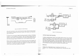
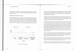
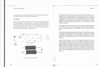
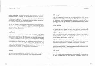
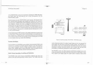
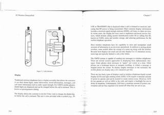
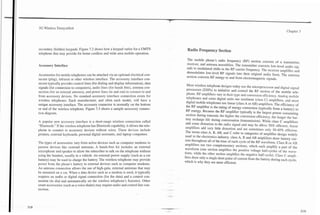
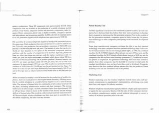
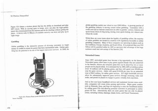
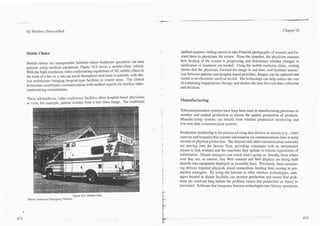
The antenna section consists of an antenna, cabling, duplexer or TR switch, and seat. An antenna cable is routed to the trunk and up to the rear window where it
possibly a coupling device for antenna connection through glass. The perfor- can be connected to the coupling box of a glass mounted antenna. The coupling
mance of the antenna system can enhance or seriously reduce the performance box of the glass-mounted antenna operates like a capacitor that allows the signal
of the ireless telephone. The antenna may be an integral part of the transceiver to pass through the glass to the base of the antenna. The antenna then converts
section (such as a portable handset) or externally mounted (on the top of a car). the electrical energy into radio waves that are transmitted to and from the cell
Antennas can have a signal gain characteristic that describes the ability of the site.
antenna to focus or concentrate the radiated energy into a particular direction
(narrov beam width) area rather than radiate it in all directions indiscriminately. q p i c a l antennas are a quarter-wavelength long. Wavelength is the distance a sig-
This focused energy gives the wireless telephone the ability to communicate over nal travels at the speed of light in on signal cycle. Because the speed of light is
greater distances. Unfortunately, as the angle of the antenna changes, the direc- 300 million meters per second, a 300-MHz signal has a wavelength of 1 meter.
tion of the beam also changes, reducing performance. For example, car-mount- A 2000-MHz signal has a wavelength 15 cm (5.9 inches), and a 900-MHz signal
ed antennas that have been tilted to match the style lines of the automobile often has a wavelength of 33 cm (13 inches). Wireless telephones may have the capa-
result in extremely poor performance.
In early vehicle-mounted wireless telephones, separate antennas were used for
transmitters and receivers to prevent the high-power transmitters from overpow-
ering rhe receiver. A duplexer or a transmitlreceive (TR) switch allows a single Coupling
antenna to serve both the transmitter and receiver. A duplexer consists of two RF Box
I +--Antenna
filters: one for transmission, one for reception. A duplexer is required for the 3
WCDMA and CDMA2000 transmission system. It is possible to use a simple TR
swirch for the TD/CDMA system. The TR switch connects either the transmitter
or the receiver to the antenna. but never at the same time.
For vehicle-mounted mobile telephones, the cabling connects the transmitter to
the external antenna experiences signal attenuation (losses) that reduces the per-
formance of the antenna assembly. This loss ranges from approximately 0.01 to
0.1 dB per foot of cable. High-gain antennas may be used to overcome these
losses and possibly allow for a lower power output [I]. control
Cable
LCable
Antenna
Figure 7.6 shows a vehicle-mounted mobile telephone antenna system. The
mobile radio transceiver is typically mounted in the trunk of the car or under a
- - -.
Figure 7.6. Mobile Telephone Antenna System.](https://image.slidesharecdn.com/29784614-3g-wireless-demystified-120918184903-phpapp01/85/3-g-wireless-demystified-178-320.jpg)
![3G Wireless Demystified Chapter 7
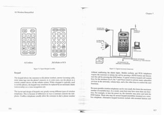
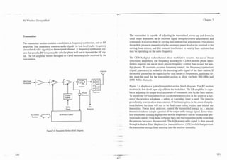
Voice Activation
Another optional feature is voice activation which allows calls to be dialed and
controlled by voice commands. To improve driving safety, it is recommended
that a call should not be dialed by a handset keypad while driving [2]. However.
it may be possible to via voice activation without significant distraction.
Two types of speech recognition exist-speaker dependent and speaker inde-
pendent. Speaker-dependent recognition requires the user to store (program)
their voice commands that are to be associated with a particular command. These
recorded commands are used to match words spoken during operation. Speaker-
independent recognition allon-s multiple users to control the telephone without
the recording of a particular .oice. Speaker-independent recognition is general-
ly less accurate than speaker-dependent recognition, and often may require the
user to repeat the command if not recognized the first time. To prevent acciden-
tal operation of the cellular telephone by words in normal conversation, key
words such as "phone start" are used to indicate a voice command..
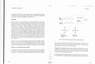
Battery Chargers
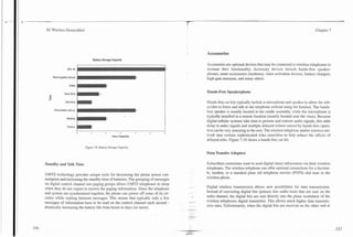
Figure 7.10. Hands-Free Speakerphone
Source: Cellport There are two types of battery chargers: trickle and rapid charge. A trickle charg-
er will slowly charge up a battery by only allowing a small amount of current to
the base station, they must be converted to a format that can be transmitted
be sent to the wireless telephone. The battery charger may also be used to keep
through the public switched telephone network (PSTN).
a charged battery at full capacity if the telephone is regularly connected to an
external power source (such as a car's cigarette lighter socket). Rapid chargers
To connect a UMTS wireless telephone to a computer, a data transfer adapter is
allow a large amount of current to be sent to the battery to fully charge it as soon
required. This data transfer adapter plugs into the bottom of a wireless telephone
as possible. The limitation on the rate of charging is often the amount of heat
and connects to a personal computer memory card adapter (PCMCIA) slot or
generated. That is, the larger the amount of current sent to the battery, the larger
serial port on a computer or data device.
the amount of heat.](https://image.slidesharecdn.com/29784614-3g-wireless-demystified-120918184903-phpapp01/85/3-g-wireless-demystified-185-320.jpg)
![-
I 3G Wireless Demy stified Chapter 8
which is designed to produce a special internal electromagnetic field pattern
called a standing wave, with dimensions that allow only a specific range of fre-
quencies (and their corresponding wavelengths) to pass. To change the resonant
frequency, the chamber's dimensions can be changed by moving a threaded
metal rod inside it either manually by a screw device or automatically changed
by a senro motor (for autotune combiners). Turning the rod to extend it further
into the cavity produces resonance and a peak bandpass frequency that is lower
(and corresponds to a longer wavelength), while shortening the length of the rod
inside the cavity raises the resonant frequency (corresponding to a shorter wave-
length).
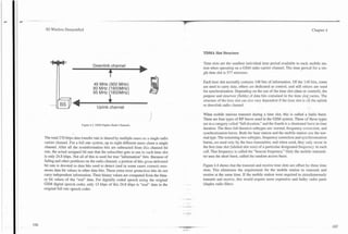
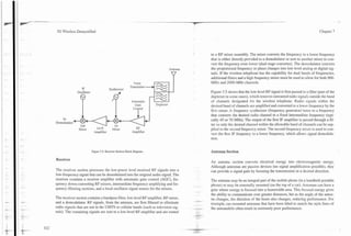
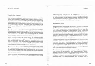
Receiver Multicoupler AI LOW NOISE
PREAMP
m l SPLITTER
LOSS
To allow one antenna to serve several receivers, a receiver multicoupler must be TO
attached to each receiving antenna. Figure 8.3 illustrates a receiver multicoupler 4 -
-
b
RECEIVER
assembly. Because a receiver multicoupler output is provided for each receiver CABLE LOSS WAY
antenna input, the splitting of received signal reduces its total available power to 2nd PREAMP
each individual receiver. By increasing the number of receivers, the signal to (+lOdBJ
noise ratio to each receiver section is reduced. Low-noise RF preamplifiers are Figure 8.3. Receiver Multicoupler.
included with the multicoupler to boost the low-level received signals prior to the
RF multicoupler splitter.
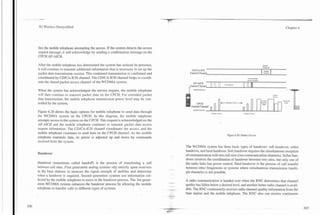
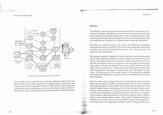
Regardless of the physical type of communication link, the channel format is
Communication Links usually the same. Communication links are typically digital time-multiplexed to
increase the efficiency of the communication line. The standard format for time-
Communication links carry both data and voice information between the MSC, ' multiplexing communication channels between cell sites in North America is the
GSN, RNCs. and the base stations. Options for the physical connections include 24-channel T I line, or multiple TI channels. The standard format outside of
wire, microwave, or fiber-optic links. Alternate communication links are some- North America is the 32-channel (30 useable channels) El line.
times provided to prevent a single communication link failure from disabling
communication [I]. Some terrain conditions may prohibit the use of one type of Figure 8.4 illustrates T1 (North American) and E l (European) standard cornmu-
communication link. For example, microwave systems are not usually used in nication links. ~ h T I communication link is divided into time frames that con-
k
extremely earthquake-prone areas because they require precise line-of-sight con-
nection. Small shifts in the earth can misalign microwave transceivers to break
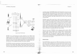
communications.](https://image.slidesharecdn.com/29784614-3g-wireless-demystified-120918184903-phpapp01/85/3-g-wireless-demystified-192-320.jpg)
![. ..
-
Wireless Demystified Chapter 8
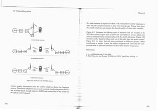
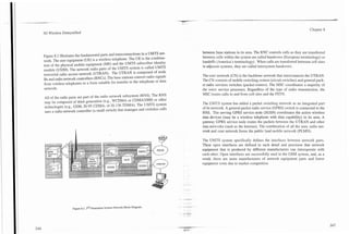
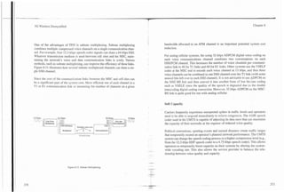
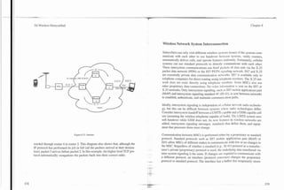
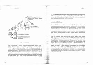
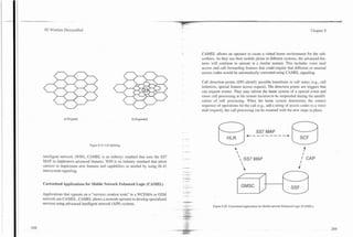
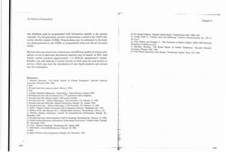
Figure 8.5 shows a functional diagram of an ATM packet switching system. This
diagram shows that there are three signal sources going through an ATM network
to different destinations. The first signal source (signal 1) is a 64-kbps voice cir-
cuit. The data from the voice circuit is divided into short packets and sent to ATM
switch 1. ATM switch 1 looks in its routing table and determines the packet is
destined for ATM switch 4, and ATM switch 4 adapts (slows down the transmis-
sion speed) and routes it to it destination voice circuit. The routing from ATM
switch 1 to ATM switch 4 is accomplished by assigning the ATM packet a virtu-
al circuit identifier (VCI) that the ATM switch can understand (the packet rout-
ing address). This VCI code remains for the duration of the con~munication. The
second signal source (signal 2) is an 384-kbps Internet session. ATM switch 1
determines that the destination of these packets is ATM switch 3, and ATM
switch 3 routes these packets to the Internet data network. The third signal source
(signal 3) is a 1 Mbps digital video signal from a digital camera. ATM switch 1
determines this signal is destined for ATM switch 2, and ATM switch 2 routes
this signal to a digital television.
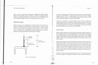
Antenna Assembly
When a wide area cellular system is first established, base station antenna assem-
blies usually employ horizontally omnidirectional antennas [2]. As the system
Figure 8.5. ATM Packet Switching.
matures, directional (sectored) antennas replace the original antennas to reduce
interference. An antenna assembly in each sector usually consists of one trans-
nel to transfer the incoming packet to and what priority should be given to the mitting antenna and two receiving antennas.
packet. The routing table is updated each time a connection is set up or discon-
nected. This allows the ATM switch to forward packets to the next ATM switch Separate transmit and receive antennas are used to keep excessive amounts of the
or destination point without spending much processing time. transmitter's RF energy from being coupled into receive antennas. The few feet
of separation between the antennas provide more than 40 dB of isolation. In
The ATM switch also may prioritize or discard packets based on network avail- some installations, where antenna tower platform space is limited. and three
ability (congestion). The ATM switch determines the prioritization and discard antennas cannot be used, one antenna must also be used for transmitting. In this
options by the type of channels and packets within the channels that are being case, a very deep notch isolatio'n filter is used to prevent the transmit signal from
switched by the ATM switch. leaking into receivers on the shared antenna.](https://image.slidesharecdn.com/29784614-3g-wireless-demystified-120918184903-phpapp01/85/3-g-wireless-demystified-194-320.jpg)
![3G Wireless Demystified Chapter 8
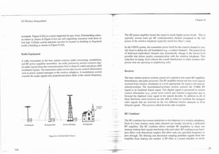
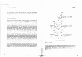
Two receive antennas may be used to provide spatial diversity reception to min- be necessary. The information from wireless telephones also reduces the data-
imize the effects of Rayleigh signal fading. Raleigh signal fading is position (dis- communications traffic burden of communications between adjacent base sta-
tance) sensitive and results when two signals are received from the same source tions while coordinating (passing signal quality information) the handover
and one of these signals is slightly delayed resulting in signals canceling. Using process.
two receiving antennas enables diversity reception that allows the selection (or
signal combining) from the antenna that is receiving the stronger signal. The
technique improves power reception up to 6 dB or more, improves the signal to Power Supplies and Backup Energy Sources
noise ratio (S/N) up to 3 dB or more, and reduces the effects of fading signals.
Power supplies convert the base station power source to regulated and filtered
AC and DC voltage levels required by the base station electronics assemblies.
Scanning or Locating Channel (Receiver) Batteries and generators are used to power a base station when primary power is
interrupted. Backup power is also needed for radio equipment and cooling sys-
UMTS systems have a frequency reuse of one that allows existing base station tems.
equipment to monitor the signal quality level of wireless telephones that are
operating on nearby cell sites. This information is used for the handover process. Backup power supplies are critical for disaster situations where power may not.
When the signal strength falls below a level or the bit error rate (BER) increas- be available for several days or even weeks. A good example of the requirements
e s beyond a specific limit, the base station signals the RNC that a handover will for short- and long-term backup power sources is the hurricane in 1989 that
be necessary soon. The RNC then commands one or more adjacent cell sites to destroyed almost all land line communications in parts of Puerto Rico. Due to
monitor the wireless telephone's radio channel code and continually measure good planning, wireless communications were unaffected and became the pri-
and report the signal strength. The RNC (or other base station controller) com- mary communication link [3].
pares the reported signal strength with other signal levels to decide handoff.
Backup power supplies are also required to ensure the equipment environment
For first generation cellular systems, a scanning or locating receiver is used to can be maintained. In most climates, the heat generated by the radio equipment
measure wireless telephone signal strength for handoff decisions. Because first in the base station shelter will require installation of air-conditioning equipment
and second generation systems used 'different frequencies in adjacent cells, a : ., to prevent excessively high temperature in the shelter. If the base radio equip-
scanning receiver can tune to any channel and measure the received signal . .. ment is permitted to operate at higher than rated temperature (for example, due
strength, from which it determines a wireless telephone's approximate distance . .
to a failure of the cooling equipment), it may malfunction temporarily (until the
, ,
from the base station. shelter temperature is lowered). Operating at excessive temperatures can
. increase the long-term costs due to higher failure rates. Operating at high tem-
- --.
The 3rd generation UMTS system allows for handover decisions to be assisted peratures can result in significantly shortening the "burn out" lifetime of many
. ...
by information reported by the wireless telephone and by simultaneous trans- . .
. of the components, particularly the RF power amplifiers.
missions during soft handover. Using signal and interference levels measured by ~
"*PBii..
wireless telephones, the UMTS system can better decide when a handovers may ..
-. --..
.-
-](https://image.slidesharecdn.com/29784614-3g-wireless-demystified-120918184903-phpapp01/85/3-g-wireless-demystified-195-320.jpg)


This document contains the table of contents for a book on 3G wireless technology. It lists the chapters and sections that will be covered, including: - An introduction to mobile wireless systems such as cellular, cordless phones, wireless LANs, and satellites. - An overview of the evolution of cellular standards from 1G analog to 2G digital to 2.5G and 3G systems with enhanced data capabilities. - Details on digital cellular radio technologies such as multiple access methods, signal processing techniques, and protocols. - Explanations of 2.5G technologies like GPRS and EDGE that improved data services over 2G networks. - Descriptions of core 3G technologies