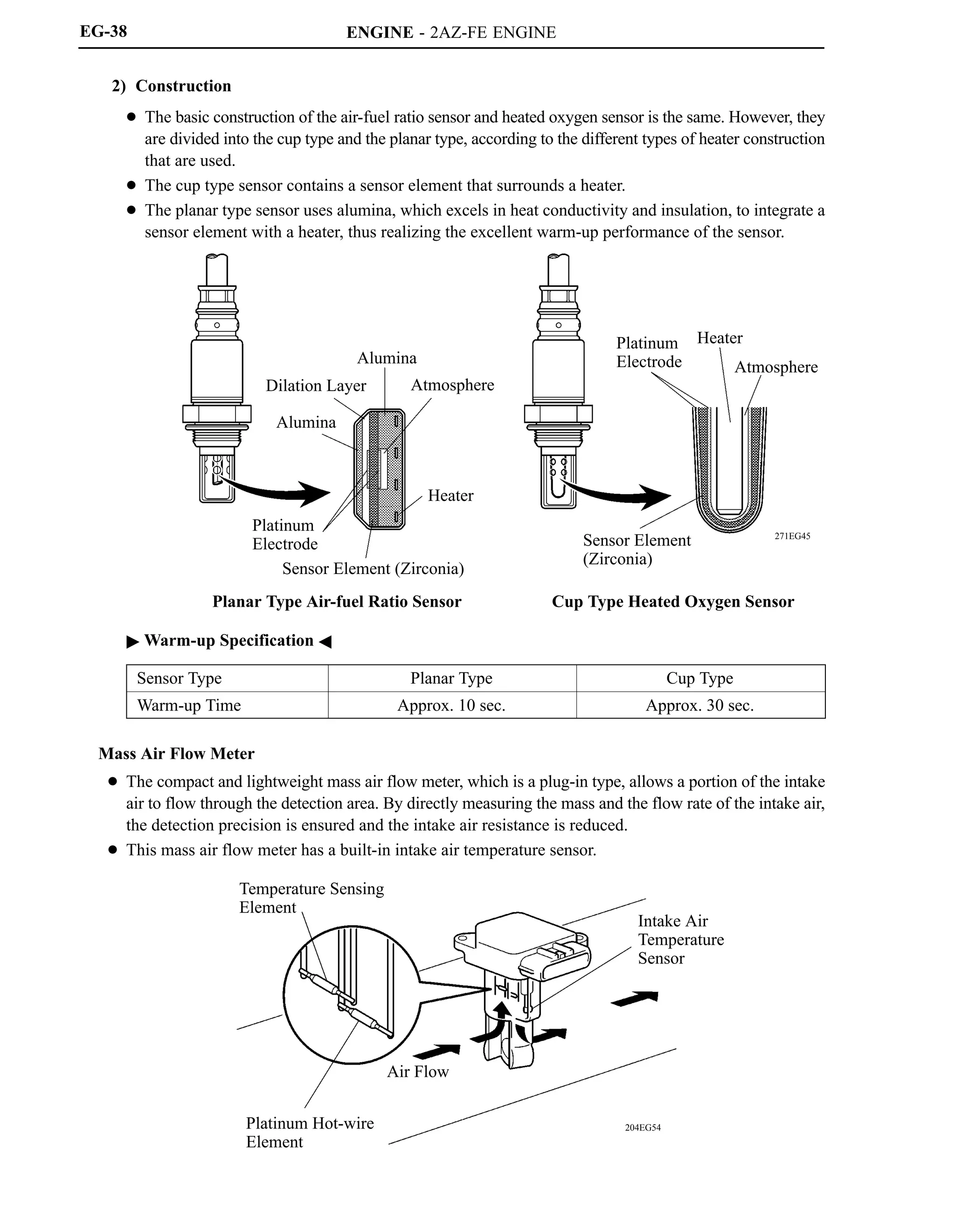
This document provides information on a new 2AZ-FE engine model, including:
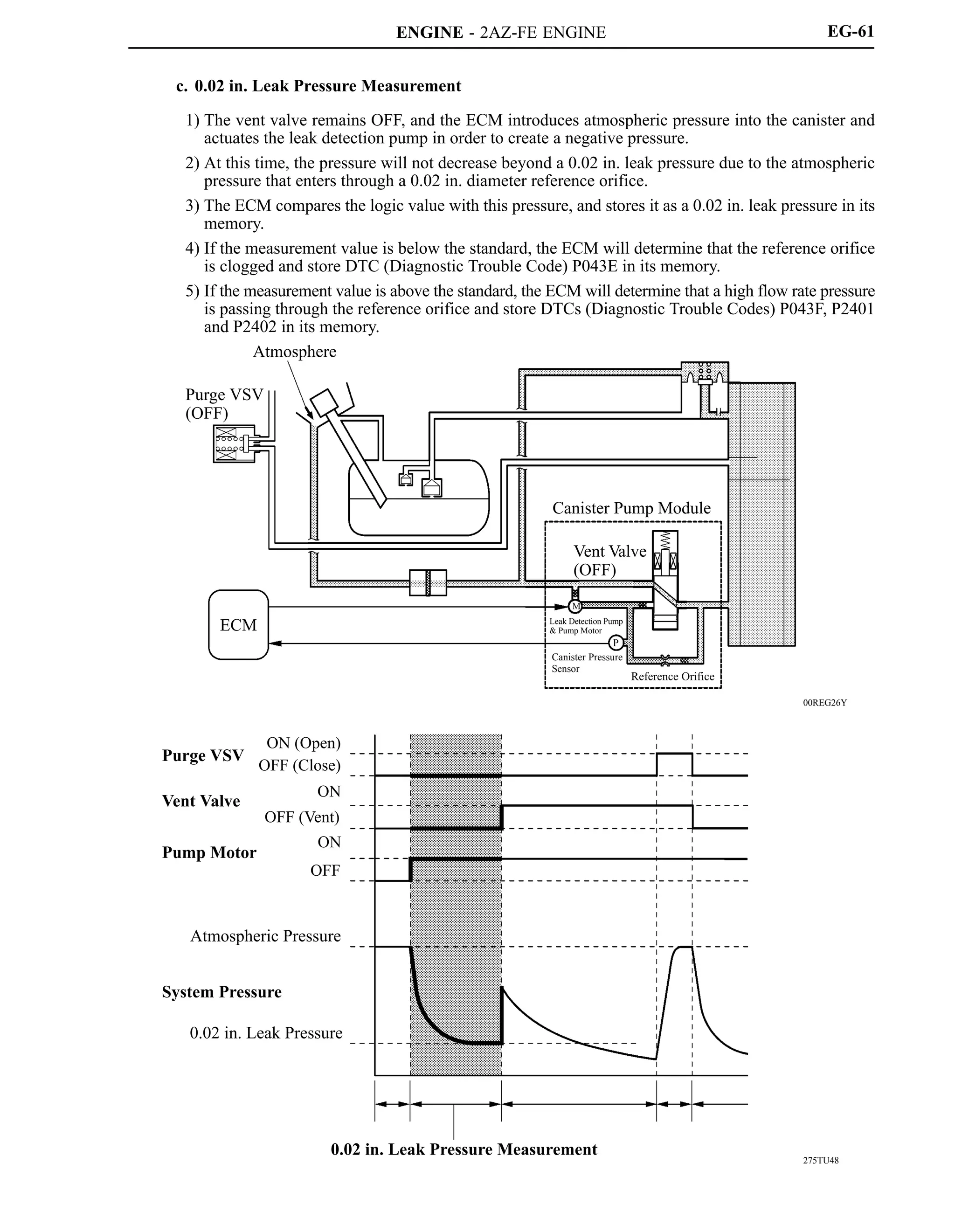
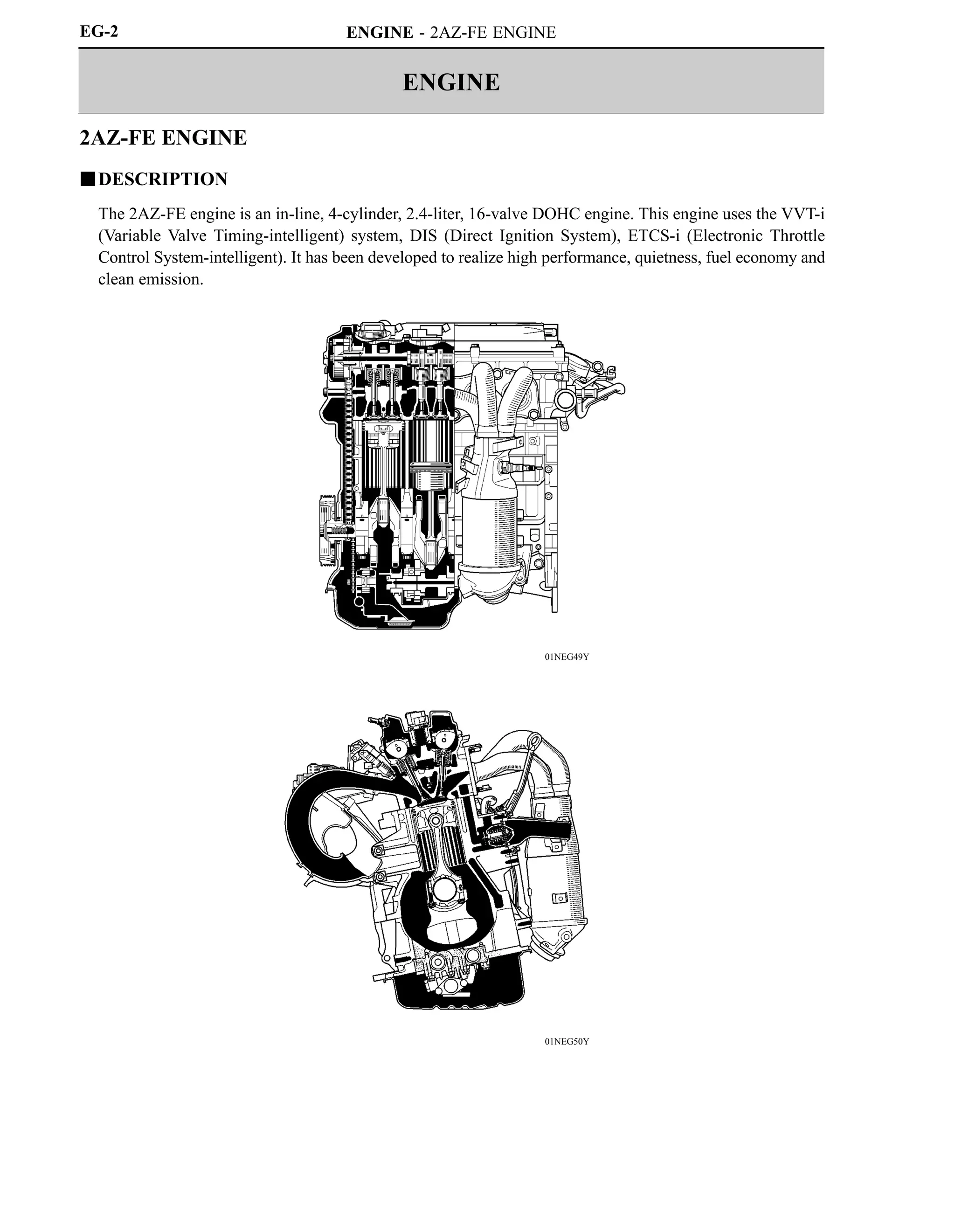
- The 2AZ-FE engine uses VVT-i and other technologies to achieve high performance, fuel efficiency, and low emissions.
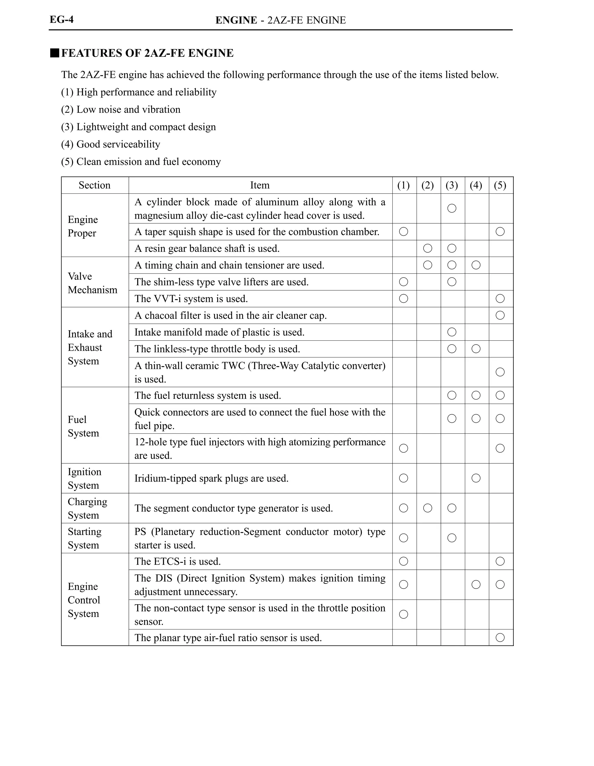
- Key specifications and features of the 2AZ-FE engine such as its 4-cylinder inline configuration, valve timing, output, and materials used.
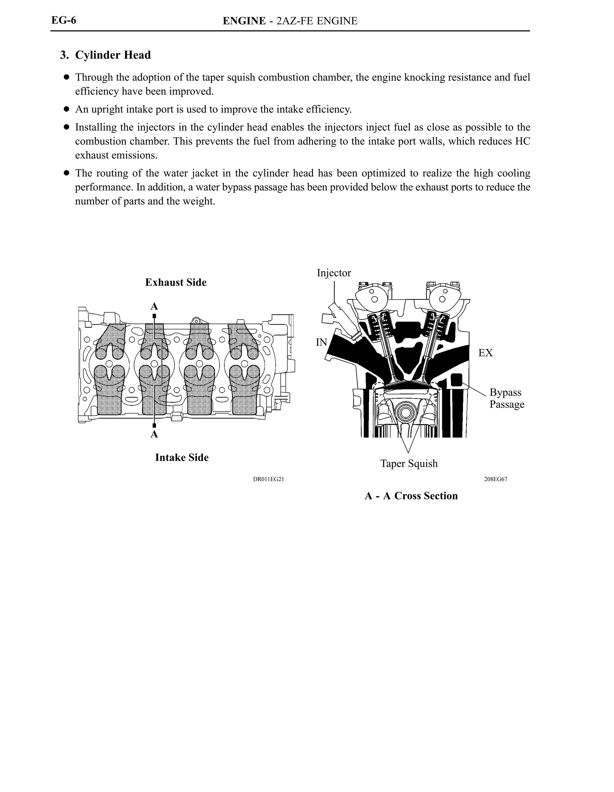
- Design elements that contribute to the engine's performance, including a tapered squish combustion chamber, lightweight materials, and integrated components.
![NEW MODEL OUTLINE
01MMO40Y
01MMO39Y
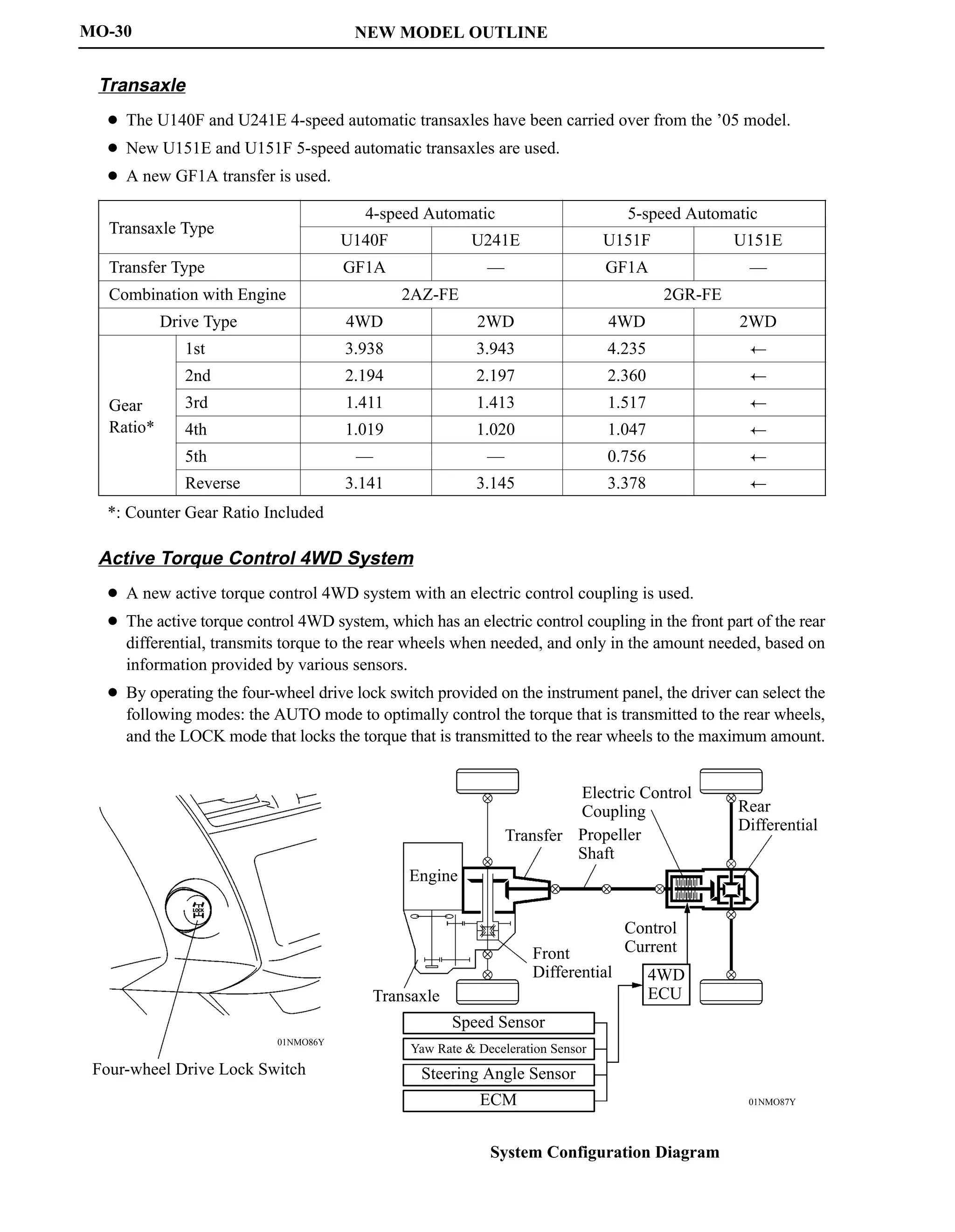
Torque
(N.m) (ft.lbf)
240
220
200
180
160
140
180
160
140
120
100
1000
Output
(HP) (kW)
180
160
140
120
100
80
60
40
20
0
140
120
100
80
60
40
20
0
2000 3000 4000 5000 6000 7000
Engine Speed (rpm)
2AZ-FE Engine 2GR-FE Engine
Torque
(N.m) (ft.lbf)
340
320
300
280
260
240
260
240
220
200
180
1000
Output
(HP) (kW)
280
260
240
220
100
80
60
40
20
0
140
120
100
80
60
40
20
0
2000 3000 4000 5000 6000 7000
Engine Speed (rpm)
200
180
160
140
120
200
180
160
MO-29
PERFORMANCE
Power Train
Engine
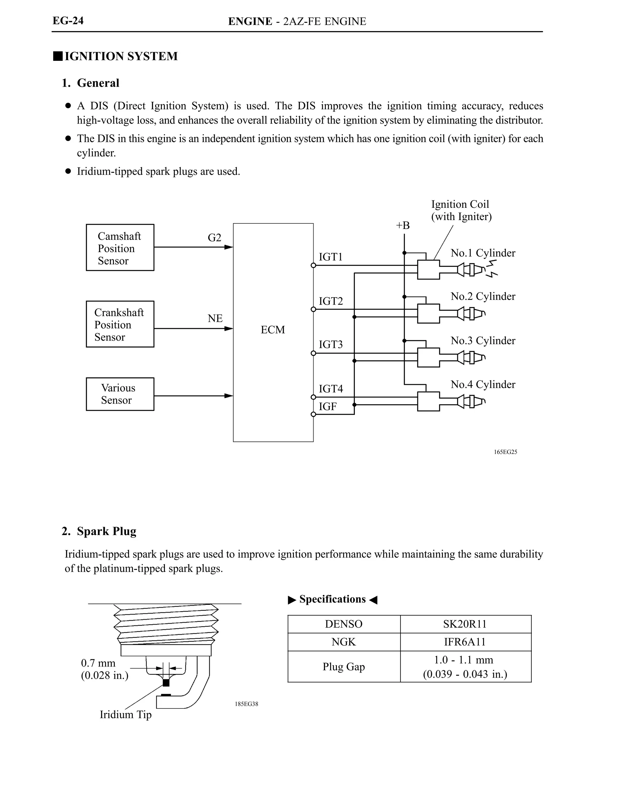
The 2AZ-FE engine has been carried over from the ’05 model. This engine realizes high performance,
quietness, fuel economy, and clean emissions through the use of the VVT-i (Variable Valve
Timing-intelligent) system, DIS (Direct Ignition System), and ETCS-i (Electronic Throttle Control
System-intelligent).
A new 2GR-FE engine is used. It realizes high performance, quietness, fuel economy, and clean emission
through the use of the Dual VVT-i (Dual Variable Valve Timing-intelligent) system, DIS, and ETCS-i.
Engine Type 2AZ-FE 2GR-FE
No. of Cyls. Arrangement 4-cylinder, In-line Type 6-cylinder, V Type
Valve Mechanism
16-valve DOHC,
Chain Drive (with VVT-i)
24-valve DOHC,
Chain Drive (with Dual VVT-i)
Displacement cm3 (cu. in.) 2362 (144.2) 3456 (210.9)
Bore x Stroke mm (in.) 88.5 x 96.0 (3.48 x 3.78) 94.0 x 83.0 (3.70 x 3.27)
Compression Ratio 9.8 : 1 10.8 : 1
Maximum Output [SAE-NET]*
124 kW @ 6000 rpm
(166 HP @ 6000 rpm)
200 kW @ 6200 rpm
(268 HP @ 6200 rpm)
Maximum Torque [SAE-NET]*
224 N.m @ 4000 rpm
(165 ft.lbf @ 4000 rpm)
336 N.m @ 4700 rpm
(248 ft.lbf @ 4700 rpm)
*: Maximum output and torque rating are determined by revised SAE J1349 standard.](https://image.slidesharecdn.com/2az-fe-221107204922-ca75a785/75/2AZ-FE-pdf-1-2048.jpg)


![ENGINE - 2AZ-FE ENGINE
279EG26
D13N17
279EG25
Fresh Air
Canister
Pressure Sensor
Leak Detection Pump
Pump Motor
Vane Pump
Canister
Pressure Sensor
Vent Valve
Fresh Air
Canister
Canister Pump Module
Fresh Air
Vent Valve
Filter
Filter
M
Leak Detection Pump
Pump Motor
Canister
Pressure Sensor
P
Reference Orifice
[0.5 mm (0.02 in.) Diameter]
Filter
To Canister
EG-57
3) Canister Pump Module
Canister pump module consists of the vent valve, leak detection pump, and canister pressure sensor.
The vent valve switches the passages in accordance with the signals received from the ECM.
A DC type brushless motor is used for the pump motor.
A vane type vacuum pump is used.
Simple Diagram](https://image.slidesharecdn.com/2az-fe-221107204922-ca75a785/75/2AZ-FE-pdf-60-2048.jpg)