030
072
096
106
MULTI V i
MULTIV S
MULTI V M
MULTI V WATER 5
028
OUTDOOR UNITS
028 ~ 123
204
HYDRO KIT
202
HOT WATER
SOLUTION
202 ~ 213
232
AHU SOLUTION
232 ~ 243
332
344
MECHANICAL ACCESSORIES
PIPING ACCESSORIES
330
ACCESSORIES
330 ~ 355
250
268
294
INDIVIDUAL CONTROL
CENTRALIZED CONTROL
INTEGRATION DEVICE
244
CONTROL
SOLUTIONS
244 ~ 329
WALL MOUNTED
CEILING MOUNTED CASSETTE
CEILING MOUNTED ROUND CASSETTE
CEILING CONCEALED DUCT
FRESH AIR INTAKE
CEILING & FLOOR CONVERTIBLE
CEILING SUSPENDED
CONSOLE & FLOOR STANDING
FLOOR STANDING (PAC)
COMPATIBILITY &
FEATURE FUNCTIONS
124
INDOOR UNITS
124 ~ 201
126
140
160
164
177
180
186
193
196
I
N
D
E
X
216
225
227
ERV
ERV WITH DX COIL
RESIDENTIAL ERV
214
VENTILATION
SOLUTIONS
214 ~ 231
003
002
3.
THE EU BUILDINGSECTOR
Buildings account for 40% of the total carbon emissions in Europe. The building stock that dates
back to the 90s is three times less energy e cient than the new construction built today.
40% 36%
OF EU ENERGY IS USED BY THE BUILDING SECTOR,
MAKING IT THE SINGLE LARGEST ENERGY
CONSUMER IN EUROPE
OF GREENHOUSE GAS EMISSIONS
COMES FROM BUILDINGS
RE-DESIGN
LG : OUR MISSION
CERTIFICATIONS
IMPROVE CIRCULARITY OF RAW MATERIALS
We minimize environmental impact with our eco-conscious air
conditioning solutions. By reducing reliance on nite resources
such as plastic, aluminum, and copper, LG's innovative approach
embraces a circular economy supply chain. This not only lessens
carbon emissions during pre-manufacturing but also ensures
resource e ciency, particularly for energy-hungry materials.
Discover the sustainability of LG air conditioners, where recycled
materials play a pivotal role. We conduct thorough stability and
quality tests to guarantee optimal performance, leading the way
toward a more sustainable and e cient future.
RE-PROGRAM
ACHIEVE 95% WASTE RECYCLING AT PRODUCTION SITES BY 2030
At LGE, we continuously invest in environmental facilities and improve our
waste treatment processes with a view to being able to recycle 95% of
waste generated at production sites around the world by 2030.
LG Electronics is listed in the:
- DJSI World for 9 consecutive years
- 2020 Global Sustainability Leadership top 100, announced by
Privileged United Nationals Sustainability Development Goals
(UNSDGs)
- 6th
place in the top 100 World Sustainable Management Companies
by Wall Street Journal
- ECOVADIS Platinum certi ed in 2021 & 2023
RECYCLING OLD APPLIANCES
Many reusable resources are left in discarded products. Founded
in 2001 through investment from LG, the Chilseo Recycling Center
acts as a virtuous cycle of resources, from product design, use,
and recovery, to disposal. Engineers collect old appliances from LG
and other brands, then carefully take them apart. More than 40
kinds of renewable raw materials, including separated plastic, iron,
and non-ferrous metals, are reborn into new LG products.
① Create low-consuming or self-consuming innovations
② Build awareness and help people use energy more conservatively
③ Reimagine a building’s usability, connectivity, convenience & health
* Source: The European Commission website. https://commission.europa.eu/news/focus-energy-e ciency-buildings-2020-02-17_en
INNOVATE
REDUCE RELIANCE ON HIGH GWP REFRIGERANT GASES
While they are not the biggest contributors, refrigerant gasses do contribute to global warming. LG was the rst manufacturer to
launch an R32 monobloc air-to-water heat pump in 2018 and have also converted our full single split lineup to R32 with 3 years lead
time on the EU-driven planned ban in 2025. Also, LG is likely to put in place collection and recovery streams of refrigerant gases from
end-of-life equipment at no extra cost for its customers.
CONSTANT PRODUCT EFFICIENCY IMPROVEMENTS
Electrically-driven heating and cooling equipment is LG’s signature.
What's more, we always aim for the highest energy ratings with
each generation of our products.
FIRST HOME APPLIANCES LIGHTHOUSE FACTORY
In March 2022, Changwon LG Smart Park was named the rst 'lighthouse factory' bu the World Economic Forum (WEF). The WEF
“Lighthouse” facilities implement Fourth Industrial Revolution technologies, such as the Internet of Things, big data, arti cial
intelligence and robots into manufacturing and supply chain operations to deliver a wide range of bene ts, from increased production
e ciency to enhanced environmental sustainability. LG plans to apply the innovative, smart production technologies pioneered at LG
Smart Park to a total of 26 LG production facilities in 13 countries, accelerating the digital transformation of its global manufacturing
network by 2025.
of old appliances
become new resources
Target amount of e-waste collection
2021 achievement
2030 target
3.52M Tons
8M Tons
Reduce the carbon emissions of our 7 major products
(baseline year 2020)
2021 achievement 2030 target
85%
Amount of recycled plastic that
LG used in previous years
Targeted use of
recycled plastics
2017
2018
2019
2020
2021 achievement
2030 target
27,000
Tons
600,000
Tons
11,149 Tons
9,282 Tons
11,030 Tons
7,134 Tons
CO2
6.6% 20%
005
004
4.
EU MARKET TRENDS
Moree cient HVAC systems are required to signi cantly reduce
energy consumption and to meet energy regulations.
- The EU reinforces its e orts to stimulate energy e ciency
as part of its 2050 decarbonization objectives
- HVAC accounts for more than 50% of a building’s energy
consumption
Environment
- Cutting emissions by at least 55% by 2030.
- EU targets a minimum reduction of 80% in carbon emissions by 2050.
Low-carbon Strategy (Targets compared to 1990)
2005 2030 2050
Power
(CO2)
Industry
(CO2)
Transport
(incl, CO2, aviation,
excl, maritime)
Residential &
Services
(CO2)
Agriculture
(other than CO2)
Total
- Global warming in Europe is faster than the rest of world
according to the IPCC
- AI, big data, 5G, and cloud technologies can improve the
human lifestyle
- For a comfortable environment, humidity has to be considered
Efficiency
Increase of average yearly temperature in selected cities in Europe
(1900–2017)
* Source : European Commission
Source : brusselstimes
- Climate change increases the need for more e cient
mechanical HVAC systems and energy usage
- Electricity and gas prices are constantly rising for a
number of reasons, such as growing energy demand,
taxes, oil prices, wars, etc
Soaring Energy Prices in Europe
2022
400 /Mwh
350 /Mwh
300 /Mwh
250 /Mwh
200 /Mwh
150 /Mwh
100 /Mwh
50 /Mwh
0 /Mwh
2018 2019 2020 2021
Electricity (EPB5)
Gas
Electricity & Gas price
Wholesale Prices EU27
+1.5°-
+1.2°-1.5°
+0.9°-1.2°
+0.6°-0.9°
+0.3°-0.6°
+0.0°-0.3°
-7%
-20%
+30%
-12%
-20%
-7%
-54% ~
-68%
-34% ~
-40%
+20% ~
-9%
-37% ~
-53%
-36% ~
-37%
-40% ~
-44%
-93% ~
-99%
-83% ~
-87%
-54% ~
-67%
-88% ~
-91%
-42% ~
-49%
-79% ~
-82%
007
006
5.
LG Air ConditioningAcademy
LG has set up 20 o cial air conditioning academies in Europe,
teaching much needed skills to thousands of current industry
professionals including installers, consultants, designers, sales
sta and service technicians. The academy program is being used
to share expertise and educate these HVAC experts by providing
a cutting-edge technical experience with the newest and most
advanced technologies and equipment. Moreover, as LG’s entire
product range is installed on site, professionals can be trained
in a realistic way that o ers them the chance to experience the
latest products rst-hand.
European Air Conditioning
Distribution Center
LG’s European Air Conditioning Distribution Center is located in
Oosterhout, in the Netherlands. Supplying and delivering products
all over Europe, this distribution hub has contributed to smooth
and rapid delivery, including direct shipping for smaller orders
and delivery tailored to air conditioners. The hub tries to manage
inventory e ciency by taking advantage of LG EU’s established
inventory pool.
MULTI V BRAND HISTORY INFRASTRUCTURE IN EUROPE
Air Conditioning Academy
Europe Energy Lab
European Distribution Center
HISTORY OF MULTI V LEADERSHIP
· Energy Saving with AI Engine
· Adaptive Noise Control
· Smart Diagnosis Reporting
· Remote Upgrade System
· Weather Information Interlocking Control
· Dual Sensing Control
· Ultimate Inverter Compressor
· Large Capacity ODU with
Biomimetic Technology Fan
· Continuous Heating
· Ocean Black Fin
· Active Refrigerant Control
· Variable Heat Exchanger Circuit
· Smart Load Control
· Smart Oil Return
· Vapor Injection (Advanced)
2013 2017 2023
MULTI V is recognized for its technology and innovation.
Superior customer experience
with AI Technology
AI Engine
nnovative
ntelligent
nteractive
NEW
All Inverter
Dual Sensing
E ciency and Comfort
with dual sensing control
009
008
6.
ENGINEERING TOOLS &SUPPORT
From planning to service & maintenance and then to de-construction, an architectural project goes through many stages from the
beginning to the end of its lifecycle. Along those stages, various engineering tools are applied to solve the diverse issues happening
in each stage, with the most optimal solution possible. Given the usage of such tools, buildings are e ectively designed, built,
supervised, and maintained throughout their lifecycle.
Dedicated to provide the best HVAC engineering support, LG Electronics Air Solution Business Unit o ers several engineering tools
and solutions focused on HVAC. Among them, the LATS* Program series has been developed to o er the best tool for LG HVAC
systems, providing our customers with a solution that allows for faster, easier and more accurate model selection, draft energy
estimations and more.
* LATS : LG Air-conditioner Technical Solution
II
Model Selection
& Design
I
Energy Estimation
& Energy Modeling
III
Installation
Environment
Analysis
LATS
Energy
Simple energy
estimation
for proposal
Energy
Modeling
- eQUESTⓇ
- TRNSYS
Detailed
energy
modeling
for
comparison
LATS
HVAC
Model
Selection
for LG VRF
LATS CAD
LATS REVIT
Drawing using
CAD
for LG VRF
Spec-in
CFD
- FLUENT
Outdoor
/ Indoor environment
analysis before installation
LGMV
Planning
01
Schematic Design
02
Construction Design
04
Design Development
03
Construction
05
Service & Maintenance
06
01 Draft Energy Estimation
LATS Energy
LATS Energy is a program developed by LG to estimate energy consumption and
analyze the life cycle cost of LG commercial air conditioning systems at the early
stages of a project.
02 Building Energy Modeling
eQuest, EnergyPro, Trace700 and More
These are certi ed commercial programs which assess a HVAC system's e ciency
and a building’s annual energy savings for building standards or certi cations, like
LEED. LG HQ supports these programs for the project stages of Design Development
and Construction Design where the overall design is nished.
03 Model Selection
LATS HVAC
LATS HVAC is a model selection program that accurately and quickly selects the
most suitable LG commercial air conditioning systems for each design. In addition
to model selection, faster estimation on refrigerant piping diameter and additional
refrigerant is possible, along with auto printing of reports.
05 Environment Simulation
06 Service & Maintenance
CFD Analysis
CFD Analysis is applied to estimate indoor air ow, temperature distribution, outdoor
air ow distribution and noise level while operating VRF products.
By running a simulation before construction, engineers estimate potential issues
and nd optimal solutions for malfunctions that could occur after construction.
LGMV
LGMV o ers real-time MULTI V cycle monitoring. During start-up, LGMV can check
for normal operation as well as troubleshoot any errors. Also it helps to nd causes
of errors and solve the problem faster.
04 Design
LATS CAD
LATS CAD enables faster and more accurate 2D design of LG commercial air
conditioning systems. It also enables modules for quotation and installation
review that minimize inherent problems during installation and commissioning.
※ AutoCAD program is required.
LATS REVIT
LATS REVIT allows BIM users to have an attractive 3D design of LG commercial air
conditioning systems with embedded calculations for refrigerant and e ciency features.
※ AutoCAD Revit program is required.
011
010
7.
Benefits for
Building Owners
Benefitsfor
Consultants
E cient Management & Cost Reduction
- Fault Detection Diagnosis enables easy maintenance
with no extra manpower for regular maintenance
- Saves space, time, and installation costs by o ering
a larger capacity single outdoor unit
- More reliable heating operation provides stable
and powerful heating during unexpected extreme
environments
Versatile Solutions
- Air-cooled, Water-cooled, Heating, ERV, and Air
Handling Unit interlocking solutions
Professional Design Support
- LATS (LG Air-conditioner Technical Solution) for
draft energy estimation, model selection, HVAC
design and 3D designing
- CFD Analysis to ensure suitable solutions and
prevent malfunctions
- Energy simulation o ered to nd the optimal
solution
Optimized Convenience with HVAC Design
- Flexible combination provides more options for
designing according to customers’ preferences
- The outdoor unit noise can be restricted by the
set noise level in advance
BENEFITS OF LG MULTI V
Benefits for
Developers & Construction Companies
Benefits for
End-users
Cost Saving Operation
- High e ciency guaranteed throughout product line-up
- Overuse of the HVAC system operational costs is
prevented with AI Energy management
Smart Building Solutions
- Seamless integration with current Building
Management Systems
- User friendly interface, exible interlocking
environment, energy management and smart
individual controller for the optimized controlling
conditions and smart building management
- Expandable control system can makes building
management smart by setting up logic optimized for
the site
Green Solutions
- Hydro kit provides environmentally friendly systems with
higher energy e ciency and less carbon emissions.
Maximizing Space Utilization
- Large capacity in a compact size enhances space
utilization
Reliability at Every Stage
- Ultimate Inverter Compressor developed and
manufactured in Korea
- Corrosion resistant Black Fin & Panel for harsh
conditions operation
Comfort Cooling & Heating
- MULTI V i is able to take control by itself in various
situations through deep learning algorithms that
enable it to self-learn
- Automatic operation provides more comfort and
convenience by checking ambient weather conditions
Convenient Functions
- Low-noise operation provides a pleasant environment
Customized Comfort and Solution
- Preset monthly energy usage and consume power
according to the target that has been previously set
013
012
8.
Office
Commercial
High Rise Oce Building
Shopping Mall
Small to Medium sized O ce Building
Retail Quick Service Restaurant (QSR)
The MULTI V series revitalizes the workspace by providing fresh air at all times. LG's intelligent control solutions add comfort to
any space.
The highly e cient, energy saving MULTI V i and MULTI V M reduce operation costs and provide comfort to suit any
purpose and any interior, helping your business save extra space and reduce expenses.
Supporting efficiency with flexibility
Maximizing business, minimizing cost
APPLICATION SOLUTIONS
• MULTI V WATER 5
(with variable water flow control kit)
• DX AHU
• High Static Duct
• PDI**
• ACP 5
• MULTI V i • DX AHU • Duct
• MULTI V M
• ERV
• Hydro Kit
• 4 Way CST* / Duct
• MULTI V i / MULTI V M
• ERV
• Convertible
• Duct
• MULTI V i / S • Dual Vane 4 Way CST* / 4 Way CST* • ERV
* CST : Cassette ** PDI : Power Distribution Indicator * ESS : Energy Storage System
Residential
Hospitality
Condominium & Apartments Single Family House & Villa
The remarkably compact size and high static pressure of the MULTI V S enables optimal space solution, providing comfort to
every space through individual zone control and hot water solution.
Creating a comfortable home
Meeting diverse needs
The variety of applications that MULTI V i o ers represents a perfect opportunity for a sophisticated hotel business.
• MULTI V S • Therma V • ESS*
• MULTI V i • DX AHU • Hydro Kit • Low Static Duct • Simple Remote controller • Refrigerant leak detector
• MULTI V S
• Hydro Kit
• 1/2 Way CST
• ACS 5
• Duct
015
014
9.
Hot Water Solution
PowerConsumption Distribution Solution
Total Control via Any Device
Refrigerant Leak Detection Solution
MULTI V i with Hydro kit provides oor heating and hot water supply as well as space heating & cooling.
It is a more environmentally friendly system with higher energy e ciency and lower carbon emissions.
LG leakage detector keep the indoor space safe and guarantees the customer’s peace of mind.
Outdoor Unit
ROOM
I/O Module
Valve
Automatic shut o
(Local Supply)
Buzzer Alarm
Refrigerant
Detector
Remote
Controller
Dry Contact
Card
In case of shared power consumption in a building, a solution to distribute the power consumption amount per tenant might be necessary.
Electricity charges can be billed to each tenant by using output from the LG Power Distributor Indicator (PDI). An administrator is able to
check the power usage for each space and date as needed. If the PDI is used in conjunction with an LG central controller, the results can
be exported in excel format.
When managing multiple spaces, building administrators should be
able to control systems from wherever they are.
The LG central controller can be accessed from any web browser
that supports HTML5. The interface has been adapted to look
great and perform well on any device.
Management o ce
PC
Library
Tablet
Main administration building
Mobile
HR (Heat Recovery) Unit
Indoor Unit
(MT*/ HT**/ Wall-mount)
Outdoor Unit
Hot water
Heating
Cooling
Interlocking Operation with ERV
LG ERV DX with humidi cation function interlock operation is a solution for humidifying and ventilating the indoor space while
communicating with other IDUs and the ODU. They provide improved comfort condition, while taking into account the indoor conditions
without additional facility installation.
Communication Kit
EEV Signal
AHU
EEV* Kit
Ref. pipe (Liquid)
Ref. pipe (Gas)
Communication
Indoor Unit
Air Handling Unit (AHU) Solution
AHU is a suitable solution for cooling and heating in large spaces. With an LG AHU Comm. Kit (for both return air / supply air control)
connected to the DX coil of the AHU, LG VRF system can be applied to deliver conditioned air.
ERV DX**
(Humidi cation)
Remote Controller
ERV*
Various Applications
Hospital
Nursery Facility & School
Sanatorium
Communication Line Refrigerant Pipe
Outdoor Unit
Outdoor Unit
D
I
V
E
R
S
E
I
N
T
E
G
R
AT
E
D
S
O
L
U
T
I
O
N
D
I
V
E
R
S
E
I
N
T
E
G
R
AT
E
D
S
O
L
U
T
I
O
N
* MT = Medium temp. 50°C LWT
** HT = High temp. 80°C LWT
* Energy Recovery Ventilation
** Direct Expansion
* Electronic Expansion Valve
Power
WHM
(Watt-Hour Meter)
Pulse Signal
PDI
ACP 5
AC Smart 5
100kWh
017
016
10.
Energy Management Solution
IntegrationSolution with BMS Interlocking Solution Using Dry Contact
Interlocking Solution by Using ACU Module
BMS System
Small - Medium size building
IDU ~64 : Modbus RTU G/W
Medium - Large size building
IDU ~128 : AC Smart 5
(BACnet IP / Modbus TCP)
IDU ~256 : ACP5
(BACnet IP / Modbus TCP)
There are many BMS protocols used for the control of buildings’ various systems such as HVAC, lighting, power and security. LG has a
wide range of gateway products for di erent protocols such as BACnet, Modbus, and LonWorks. In addition, LG gateways include Stand-
alone central control capability to act as a back-up controller of the BMS if needed.
Target
Forecasting
Compressor Capacity
Control
IDU Operation
Ratio Control
IDU Operation
Level
70%
Energy navigation function allows LG MULTI V i to preset monthly energy usage and consume what has been previously planned.
By comparing and analyzing previous consumption and planned energy usage for the month, overuse of the HVAC system operational
costs can be prevented with central controller.
3rd
party thermostats can be used to control LG air conditioners in a room by using a multi point dry contact. The dry contact enables
basic control of air conditioners as well as making it possible to report the status and any errors impacting the indoor unit.
The Standard III remote controller has a DO port. With this DO port, it is possible to interlock the indoor unit with 3rd
party devices such
as lighting, a fan, or a radiator, based on parameters like operation mode or current temperature.
The indoor unit can be interlocked with various types of input such as card key-tag, door sensor, human detection sensor ect., so that
the air conditioner is automatically operated. In addition, the dry contact option settings enable the operation of the air conditioner to
maintain proper temperature when the occupant is absent. This solution makes sure that the room does not overheat or become too cold
when unoccupied so that energy cost can be saved.
Pump Lighting Fan Sensor
ACU Module
AC Smart 5 (ACP 5)
Saving Engineering Cost
Strengthen
Maintenance E ciency
It is costly to introduce a BMS system to control multiple devices or systems in a small building. With the ACU module, various IO
contact points (DI, DO, UI, AO) can be interlocked and integrated, while control is possible from the LG central controller. This enables an
e cient management of lighting, pumps and other devices in the building in conjunction with the HVAC system.
Monthly Target Setting
Control Step & Logic Selecting
( Up to 7 Steps )
Automatic Control By
Power consumption
Energy Saving Logic
D
I
V
E
R
S
E
I
N
T
E
G
R
AT
E
D
S
O
L
U
T
I
O
N
D
I
V
E
R
S
E
I
N
T
E
G
R
AT
E
D
S
O
L
U
T
I
O
N
* IDU ~ 64, Lonworks with U60FT
KNX gateway for IDU
IDU ~64 : KNX gateway
019
018
11.
6 HP
220V, 1Ø
3-6HP
220V, 1Ø
380V, 3Ø
10-12 HP
380V, 3Ø
4-8HP
380V, 3Ø
5-6HP
220V, 1Ø
4HP
220V, 1Ø
Heat Recovery
22-40 HP
380V, 3Ø
8-20 HP
380V, 3Ø
42- 60 HP
380V, 3Ø
14-20 HP
14-20 HP
380V, 3Ø
8-12 HP
8-12 HP
380V, 3Ø
22-26 HP
22-26 HP
28 HP
380V, 3Ø
28-48 HP
380V, 3Ø
50-68 HP
380V, 3Ø
70-96 HP
380V, 3Ø
5 HP
220V, 1Ø
380V, 3Ø
O
U
T
D
O
O
R
U
N
I
T
S
L
I
N
E
-
U
P
021
020
12.
Unit : HP● 380V, 3Ø ○ 220V, 1Ø * R410A, R32 Line-up
Features Appearance 3 4 5 6 8 10 12 14 16 18 20 22 24 26 28 30 32 34 36 38 40 42 44 46 48 50 52 54 56 58 60 62 64 66 68 70 72 74 76 78 80 ⋯ 96
• Large capacity ODU (Up to 26 HP)
• R32 ODU line-up (Up to 28 HP)
• Powerful cooling / heating performance
• Flexible ODU combinaion
• AI e ciency / comfort / smart up
• Scability to various applications
• Continuous Heating
• Black Fin heat exchanger
• Flexible installation
(Heat recovery unit & large capacity)
• Large space, Individual control building
Education
Shopping mall Airport
● ● ●
● ● ● ●
● ● ●
● ● ● ● ● ● ● ● ● ● ●
● ● ● ● ● ● ● ● ● ●
● ● ● ● ● ● ● ●
• Space saving
• Flexible design
Slim, light, broad range (3 -12 HP)
Large number of connectable
indoor units (Up to 20 Units)
• Small to medium buildings
Apartment House & villa
○
●
○
●
○
●
● ● ●
HEAT RECOVERY ○
○
●
○
●
○
●
○
●
• High exibility of installation
• Various indoor unit combinations
& long distance between modules
• Retail shop
Restaurant
Cafe
O ce
●
• High e ciency systems
• Indoor installation
• Low noise operation (No fan)
• Simultaneous cooling & heating
• Individual control building,
Large building
Resort
Hospital
● ● ● ● ● ● ●
● ● ● ● ● ● ● ● ● ●
● ● ● ● ● ● ● ● ● ●
O
U
T
D
O
O
R
U
N
I
T
S
L
I
N
E
-
U
P
* * *
* *
*
*
*
*
*
*
023
022
13.
kW 1.5 2.22.8 3.6 4.5 5.6 6.2 7.1 8.2 9.0 10.6 12.3 14.1 15.8 22.4 28.0
Energy
Monitoring
2 Set
Point
Occupied /
Unoccupied
Scheduling
Function
Group
Control
Test Run
(Cooling)
Test Run
(Heating)
Model
Information
Monitoring
Auto
Addressing
Refrigerant
Leakage
Detection
Thermo
On / O
Range
Setting
(Cooling)
Thermo
On / O
Range
Setting
(Heating)
StaticPressure
11StepControl
(OnlyforCeiling
Concealed
DuctType)
1 Point
External
Input
(On / O
Control)
Filter Sign
(Remaining
Time)
Auto
Restart
Function
Disable /
Enable
Wi-Fi
Ready
5k 7k 9k 12k 15k 18k 21k 24k 28k 30k 36k 42k 48k 54k 76k 96k
4th
generation
Wall
Mounted
Artcool Gallery ● ● ● ● ● ● ● ● ● ● ● ● ● ● ● ● ● ●
Artcool Mirror ● ● ● ● ● ● ● ● ● ● ● ● ● ● ● ● ● ● ● ● ● ●
Standard ● ● ● ● ● ● ● ● ● ● ● ● ● ● ● ● ● ● ● ● ● ● ● ●
4th
generation
Ceiling
Mounted
Cassette
4 Way Cassette
(570 x 570)
● ● ● ● ● ● ● ● ● ● ● ● ● ● ● ● ● ● ● ● ● ●
4 Way Cassette
(840 x 840)
● ● ● ● ● ● ● ● ● ● ● ● ● ● ● ● ● ● ● ● ●
4 Way Cassette High Sensible
(840 x 840)
● ● ● ● ● ● ● ● ● ● ● ● ● ● ● ● ● ● ● ● ● ● ● ● ● ●
Round Ceiling Cassette ● ● ● ● ● ● ● ● ● ● ● ● ● ● ● ● ● ●
2 Way Cassette ● ● ● ● ● ● ● ● ● ● ● ● ● ● ● ● ● ● ●
1 Way Cassette ● ● ● ● ● ● ● ● ● ● ● ● ● ● ● ● ● ● ● ●
4th
generation
Ceiling
Concealed
Duct
Mid /
High Statics
● ● ● ● ● ● ● ● ● ● ● ● ● ● ● ● ● ● ● ● ● ● ● ● ● ● ● ● ●
Low Static
(Slim)
● ● ● ● ● ● ● ● ● ● ● ● ● ● ● ● ● ● ● ● ● ● ● ●
High Sensible ● ● ● ● ● ● ● ● ● ● ● ● ● ● ● ● ● ● ● ● ● ● ● ● ● ●
4th
generation
Fresh Air Intake
● ● ● ● ● ● ● ● ● ● ● ● ● ● ● ● ● ●
4th
generation
Ceiling & Floor Convertible
● ● ● ● ● ● ● ● ● ● ● ● ● ● ● ● ● ●
4th
generation
Ceiling Suspended
● ● ● ● ● ● ● ● ● ● ● ● ● ● ● ● ● ● ● ●
4th
generation
Console
● ● ● ● ● ● ● ● ● ● ● ● ● ● ● ● ● ● ● ●
4th
generation
Floor
Standing
Floor Standing
with Case
● ● ● ● ● ● ● ● ● ● ● ● ● ● ● ● ● ● ● ● ● ●
Floor Standing
without Case
● ● ● ● ● ● ● ● ● ● ● ● ● ● ● ● ● ● ● ● ● ●
Floor Standing (PAC) ● ● ● ● ● ● ● ● ● ● ● ● ● ●
4th
generation
HYDRO KIT
Wall-Mounted ● ● ● ● ● ● ● ● ● ● ● ● ● ● ●
IWT ● ● ● ● ● ● ● ● ● ● ● ● ● ● ●
Low Temperature ● ● ● ● ● ● ● ● ● ● ● ● ● ●
High Temperature ● ● ● ● ● ● ● ● ● ● ● ● ●
4th
generation
Energy
Recovery
Ventilator with
DX Coil
with Humidi er ● ● ● ● ● ● ● ● ● ● ●
without Humidi er ● ● ● ● ● ● ● ● ● ● ●
※ If 4th
generation indoor units are combined to 2nd
generation indoor units, several functions are not available.
More detailed information, refer to the "MULTI V Indoor units Compatibility Table"
I
N
D
O
O
R
U
N
I
T
S
L
I
N
E
-
U
P
I
N
D
O
O
R
U
N
I
T
S
F
E
AT
U
R
E
O
V
E
R
V
I
E
W
025
024
14.
Individual Control CentralizedControl
Wired Remote Controller
Wireless Remote
Controller
Display Platform Gateway
Standard Simple
Deluxe AC Ez ACP 5 Modbus RTU gateway
PREMTA201 PQRCVCL0QW PWLSSB21H (Heat Pump)
PWLSSB21C (Cooling Only)
PQCSZ250S0
(Indoor Unit ~ 32)
PACP5A000
(Indoor Unit ~ 256)
BACnet IP / Modbus TCP
* ~64, Lonworks with U60FT
PMBUSB00A
(Indoor Unit ~
16 with single module
Indoor Unit ~
64 with 4 modules)
Premium Wi-Fi Modem AC Ez Touch AC Manager 5 KNX gateway
PREMTA000
PREMTA000A
PREMTA000B
PQRCVCL0Q For Indoor Unit
PWFMDD200
PACEZA000
(Indoor Unit ~ 64)
PACM5A000
(Indoor Unit ~ 8,192)
INKNXLGE016O036
(Indoor Unit ~16)
INKNXLGE064O036
(Indoor Unit ~64)
Standard III (White) AC Smart 5
PREMTB101 PQRCHCA0QW
(Simple for Hotel)
PACS5A000
(Indoor Unit ~ 128)
BACnet IP / Modbus TCP
INKNXLGE001R000
(For Indoor Unit)
Standard III (Black) PI485
PREMTBB11 PQRCHCA0Q
(Simple for Hotel)
For ERV
PHNFP14A0
Standard II (White)
PREMTB001 For ERV
PSNFP14A0 (with case)
Standard II (Black)
PREMTBB01 For AWHP
PP485A00T
For SINGLE / MULTI
PMNFP14A1
L
G
H
VA
C
C
O
N
T
R
O
L
L
I
N
E
-
U
P
Centralized Control Integration Device
Facility Integrator
Indoor Unit
Outdoor Unit AHU Kit
Dry Contact Control Accessory
PDI
(Power Distribution Indicator)
Group Control Wire
IO Module
(Input / Output Module)
Communication Kit
Premium (8 ports) PQNUD1S40
Standard (2 ports) PPWRDB000
Simple Dry Contact
PDRYCB000
PZCWRCG3 For MULTI V IV, 5, i
PVDSMN000
Return / Room Air Control
PAHCMR000
ACS IO Module
(Input / Output Module)
Remote Temperature Sensor
Variable Water Flow
Control Kit
PEXPMB000 Dry Contact for Thermostat
PDRYCB320
PQRSTA0 For MULTI V WATER 5
PWFCKN000
Discharge / Supply Air Control
PAHCMS000
ACU IO Module
UIO
Zone Controller Low Ambient Kit Controller Module
PEXPMB300 2 Points Dry Contact (For Setback)
PDRYCB400
4 Zones by thermostat
ABZCA
For MULTI V IV, 5, i
PRVC2
Main Module
PAHCMM000
UO Multi-tenant Power Module Cool / Heat Selector
PEXPMB200 For Modbus
PDRYCB500
/ PDRYCB510 (w/o case)
PINPMB001 PRDSBM Communication Module
PAHCMC000
UI Control Kit
PEXPMB100 PAHCNM000
(Max. 3 Outdoor Units)
Water Communication Module
PAHCMW000
EEV Kit (Electronic Expansion Valve)
+
PRLK048A0 ( ~ 28 kW)
PRLK096A0 ( ~ 56 kW)
PRLK396A0
( ~ 112 kW)
PRLK594A0
( ~ 168kW)
027
026
15.
028 ~ 123
MULTIV i
MULTI V S
MULTI V M
MULTI V WATER 5
OUTDOOR
UNITS
029
028
16.
M
U
LT
I
V
i
O
U
T
D
O
O
R
U
N
I
T
S
225m
Longest Piping Length
110m
HeightDi erence
between ODU ~ IDU
40m
Height Di erence
between IDU ~ IDU
1,000m
Total Piping
Length
Highlights
- Air-cooled VRF Heat Pump & Heat Recovery
- 22.4kW ~ 268.8kW (Cooling capacity based)
- 3Ø, 380 ~ 415V, 50Hz
- Top discharge outdoor unit
- Ability to function as Heat Pump or Heat Recovery
Energy
savings
Reliability Low noise
Advanced
performance
How does it work?
Type
Changeover
Interchangeable between
heat pump and heat recovery
Dual Sensing Partial Defrost
M
U
LT
I
V
i
17.
033
032
M
U
LT
I
V
i
O
U
T
D
O
O
R
U
N
I
T
S
Maximum 26HP fora Single Outdoor Unit
Compact Design with Larger Capacity
LG MULTI V i saves space, time, and installation costs by o ering a larger capacity single outdoor unit.
Lighter outdoor units reduce the installation area and architecture structure, increasing the space for roof gardens.
Install 260HP
A company
23.4 m2
17.5 m2
Installation
Area (m2
)
25 % ↓
(20HP x 13EA) (26HP x 10EA)
A company
4,520 kg
3,620 kg
Total Weight
(kg)
20 % ↓
(20HP x 13EA) (26HP x 10EA)
The Largest
Capacity in 1 Unit
Max. 26HP
Space saving
Time saving
Installation costs saving
Innovative Energy e ciency /
Performance realization
- Maximum 26HP for a Single Outdoor Unit
- Compact Design with Larger Capacity
- Powerful Performance
- Powerful Cooling Performance
- Powerful Heating Performance
- Newly Designed Compact Fan
- Flexible Outdoor Units Combination
- Corrosion Resistant
Recognizes various environments &
optimizes itself through its AI Engine
AI EFFICIENCY UP
- AI Smart Care
- AI Energy Management
AI COMFORT UP
- Adaptive Noise Control
- Noise Target Control
- Weather Information Interlocking Control
AI SMART UP
- AI Smart Diagnosis
- Large Capacity Black Box
- Auto Tuning System
- Remote Upgrade System
Upgrading & evolutionary system according to customer
-LG’s Control Solution
-Smart GUI
-New Innovative Controller
02
03
01
I
N
N
O
VAT
I
V
E
H
I
G
H
L
I
G
H
T
O
F
M
U
LT
I
V
i
A/C
(Air Conditioner)
Valve / Pump
AO (Analog Output)
Fan / Lighting / Switch
DO (Digital Output)
LG AHU
Occupancy Sensor / Alarm / Key-Tag
DI (Digital Input)
Temperature / Humidity
/ CO2 Sensor
AI (Analog Input)
Interlocking
System
※ Previous model: ARUM261LTE5, New model: ARUM260LTE6
※ This scene is designed only for easier understanding, because 26HP unit cannot be applicable.
8,280 mm
[ MULTI V i ]
11,030 mm
[ A company ]
2,750 mm
18.
035
034
M
U
LT
I
V
i
O
U
T
D
O
O
R
U
N
I
T
S
Powerful Cooling Performance
MULTIV 5 has already proved itself highly competitive in the European market in terms of efficiency levels, but MULTI V i exceeded
its predecessor.
Reliable cooling operation up to 52°C, with full performance at 43°C. End users are able to enjoy comfortable indoor environments, even
with extreme weather conditions outside.
Powerful & Stable Cooling Performance
Powerful Performance
[ Better than the Best ]
EER
Max. 15% EER
※ For certain models in the line-up.
※ Final speci cations may change slightly.
Cooling Operation Range -15 ~ 52°C -15 ~ 48°C
Performance at 43°C Full 92 %
Full
performance
at 43°C
Powerful Heating Performance
More reliable heating operation is provided at down to -30°C and full performance at -10°C. Stable heating performance is guaranteed
even in the case of an unexpected outdoor temperature drop.
Stable & Powerful Heating
Heating Performance
※ Final speci cations may change slightly.
※ The defrost process is simpli ed for easier understanding. ※ HEX: Heat Exchanger
Heating Operation Range -30 ~ 16°C -25 ~ 16°C
Performance at -10°C Full 92 %
Full
Performance
at -10°C
Improved design for defrost with an independent HEX system and accumulated freezing prevention design. With a di erentiated structure and design,
it provides longer heating time and reduced defrost time.
Improved design
Full performance at -10°C
7 0 -5 -7 -10 -20 -25 -30
65
60
55
50
45
kW
Temp.
Continuous Heating
The heating operation duration was extended by
independent HEX system for defrosting.
Competitors
0 10 20 30 40 50 60
50
50
40
40
30
30
20
20
Time
(min)
Heating
Defrosting
Heating
Defrosting
(Stop Heating)
NEW Accumulated Freezing Prevention Design
After defrost,
ice is the deposited
on the HEX
IDU Ref. temp.(℃)
Time
(min)
0 10 20 30 40 50 60
Heating
Heating
Heating Heating
IDU Ref. temp.(℃) After defrost,
less ice is the
deposited
on the HEX
Preventing the freezing of the lower part of the heat
exchanger
Competitors
Indoor outlet air temperature deviation
during heating minimum load operation
70%
1
2
3
Defrost Time
Reduction
65%
Continuous Heating
1
I
N
N
O
VAT
I
V
E
I
N
N
O
VAT
I
V
E
2 3
19.
037
036
M
U
LT
I
V
i
O
U
T
D
O
O
R
U
N
I
T
S
Applicable Free Combination
NewlyDesigned Compact Fan
Flexible Outdoor Unit Combination
The design of a new biomimetic fan was inspired by nature. It brings more air volume and less noise with the same air ow rate compared
to the conventional system.
Flexible combination can contribute to faster delivery and installation. It provides more options for designing according to customers’
preferences.
※ Final speci cations may change slightly.
※ The UXC chassis models are not applicable to free combination.
※ The 26 HP model of UXC chassis cannot be combined with other models.
※ More information can be checked in the LATS tool.
Fan Noise Level
2.6dB Reduction
Fan Power Consumption
12% Reduction
The new biomimetic fan has 6 blades that can reduce noise level and power
consumption.
NEW Designed Biomimetic Fan
Humpback Whale Design
Increased Air
volume
Clam Shell Pattern
Reduced
Noise Level
With an optimal air ow, the noise level and power consumption is reduced.
Compact Aero-Design
NEW Compact Ori ce
NEW Motor Mounted Design
Standard Combination
18HP 12HP
Flexible Combination
20HP 10HP
Flexible Combination
16HP 14HP
For Customer
Faster Delivery & Installation
For Consultant
Flexible Design for higher e ciency
2 Units : 28~36 HP
3 Units : 50~56 HP
4 Units : 70~76 HP
Corrosion Resistant
“Corrosion Resistant Black Fin” heat exchanger is designed for improved corrosion resistance. Body panels are also designed for
improved corrosion resistance. 2,000 hours for body panels and 10,000 hours for heat exchanger make the product more reliable for
customers.
※ The product is not fully anticorrosive. To install near the sea, additional measures can be required.
5% Area of defects compared to initial state.
× Process repeated
※ Veri cation of corrosion resistance performance
- Test Method B of ISO21207
- ASTM B117 / (2,000 hours) (Last updated : Jul.
2022)
Salt Spray Test (SST)
Test process is conducted according to
ASTM B117
1) Salty water concentration :
NaCl aqueous solution (5%)
Conventional
Panel
New Panel
About
700 hr
2,000 hr
286 %
Fog1)
(35°C, 24hr)
Test process is conducted according to
ASTM B117.
1) Salty water concentration :
NaCl aqueous solution (5%)
Conventional
Fin
Black Fin
5,000 hr
10,000 hr
100 %
5% Area of defects compared to initial state.
× Process repeated
※ Veri cation of corrosion resistance performance
- Test Method B of ISO21207
- ASTM B117 / ISO 9227 (5,000 hours →10,000
hrs.) (Last updated : Dec. 2020)
Salt Spray Test (SST)
Fog1)
(35°C, 24hr)
Aluminum Fin
Hydrophilic Film (Water Flow)
Polyester Coating (Corrosion resistant)
Iron Panel
The Hydrophilic coating minimizes
moisture buildup on the n.
The coating provides strong protection
from corrosion.
Complex Resin (Corrosion Resistant)
The Black coating provides strong
protection from corrosion.
Panel
Fin
I
N
N
O
VAT
I
V
E
I
N
N
O
VAT
I
V
E
NEW
⋯
20.
039
038
M
U
LT
I
V
i
O
U
T
D
O
O
R
U
N
I
T
S
AI Smart Care
MULTIV i is capable of autonomous adaptation to various situations. When no one is in the space, power saving mode automatically
turns on. MULTI V i is equipped with deep learning algorithms enabling it to self-learn.
※ If more accurate status for energy consumption is needed, ACP and PDI have to be installed.
AI Energy Management
MULTI V i is able to preset monthly energy usage and consume power according to the target that has been previously set.
By comparing and analyzing previous power consumption of the current month and planned daily energy usage, overuse of the HVAC
system operational costs can be prevented by AI Energy management.
Clustering
AI Engine
Power Cooling Comfort Cooling
Data Collecting and Saving from IDU & ODU
Running time to reach target
28.5 %
Energy Saving
24.7 %
※ This is the result from internal test that is followed KS Test Standard, the result may be di ered by applied model, local temperature, and environment.
- Model : MULTI V i 57 kW - Test Standard : KS B ISO15042
Indoor and human load are high. Indoor and human load are low.
Quick & Power Cooling
Comfort ECO Cooling
LG ACP & PDI provide several smart functions for energy
management.
With MULTI V i, advanced energy consumption prediction &
managing function can be provided for small commercial sites
with no centralized controller.
Conventional
Predicting the amount
of power consumption
Adjusting the
condition set
kW
Day
Target
Usage
26℃
Setting the target power
consumption of the system
Easy Energy Usage Check
AI Engine power consumption prediction & Automatic Control
Target
Indirect Wind Volume Ref.
Power Wind Volume Ref.
Controlled by a
Remote Controller
Adaptive Noise Control
Noise Target Control
The outdoor unit’s noise level is automatically adjusted to the ambient conditions guaranteeing the customers’ peace of mind,
as they no longer have to worry about causing noise damage to neighbors.
The outdoor unit’s noise can be restricted by the set sound level in advance, allowing customers to enjoy comfortable conditions while
avoiding disturbing their neighbors and complying with the local noise regulations.
Quiet Area
Noisy Area
※ This function will be available along with the schedule below.
- single / combination unit : Production from Jan, `25
- 2 or more units / groups : Application within `26
time
Noise
Level Function OFF Function ON
Product Noise
Background Noise
time
Noise
Level
Function OFF Function ON
Product Noise
Background Noise
Controlled
by Standard III
time
65 dB
60 dB
55 dB
Noise
Level
Function OFF Function ON
Background
Noise
Available Setting
50 / 55 / 60 / 65 / 70 dB
Noise Control Operation
considering the
Background Noise
Product
Noise
I
N
T
E
L
L
I
G
E
N
T
I
N
T
E
L
L
I
G
E
N
T
21.
041
040
M
U
LT
I
V
i
O
U
T
D
O
O
R
U
N
I
T
S
Hot
Comfort
Cold
Weather Information InterlockingControl
LG MULTI V i provides more comfort and convenience by checking ambient weather conditions.
Remote Controller
※ Connecting with the AccuWeather is needed the ThinQ server.
※ The operation is based on AccuWeather information.
Rainy Snowy
Dust
Cold season
Automatic
Air cleaning
Automatic
Comfort / Energy
Saving mode
Automatic
Snow Removal
Hot
Comfort
Cold
Sensing
Temp. & Humidity
Manage Ref. Manage Ref. temp.
ThinQ
Sever
Wi-Fi
Modem
Outdoor
Indoor
Humidity
ON
Automatic
Pre-heating
AI Smart Diagnosis
AI Smart Diagnosis saves service time and provides for reliable LG MULTI V i operation by automatically analyzing and visualizing the
product’s performance status.
Mobile
LGMV
Mobile
LGMV
Large Capacity Black Box
Operation data can be saved for up to 6 months before the system failure, contributing to quick service of the product.
Service
Time Reliability
OK Check Needed Check Immediately
Product Status Index
Comp.
Sensors/Parts
Communication
Performance
Ref.
96/100
I
N
T
E
L
L
I
G
E
N
T
I
N
T
E
L
L
I
G
E
N
T
Data Saving Period
MULTI V 5
170 sec Max. 6 months
Recording operation data for
- Max. 6 months before system failure!
- Saved for 1 hour before and after the
error occurred
LGMV Smart phone Data Analysis
Service
Time Reliability
NEW
※ UI may be changed without noti cation.
※ UI may be changed without noti cation.
22.
043
042
M
U
LT
I
V
i
O
U
T
D
O
O
R
U
N
I
T
S
Auto Tuning System
RemoteUpgrade System
LG MULTI V i provides a new experience to customers with faster and easier installation and service. The AI engine is automatically
upgradable when the compressor and motor are replaced.
Like a smart phone, LG MULTI V i upgrades itself remotely! You can opt for the latest version of software immediately without on-site service
Self-Upgradable
Product
BECON Cloud
ACP 5 AC Smart 5
Auto system Update
&
Auto tuning by AI Engine
Upgrade by On-site visit Upgrade by Network
Upgrade manually with a laptop (O -line SVC) ※ Remote upgrade by BECON Cloud
※ This function is to be applied to compressor and fan motor.
※ LG BECON Cloud is needed.
Conventional
• External Device
Lighting Pump Fan Temp.
Sensor
CO2
Sensor
• Energy Management
LG’s Control Solution
LG MULTI V i o ers a diverse range of e ective control solutions that satisfy the speci c needs of each building and its user scene.
Hotel
Hotel Room Solution
O ce
Central Control Solution
3rd
Party BMS Cloud System
Residential
Smart Individual Control Solution
Apartment
Power Distribution Solution
Small Building
Small Central Control Solution
92kW
20kW
50kW
Integration Solution
I
N
T
E
R
A
C
T
I
V
E
I
N
T
E
L
L
I
G
E
N
T
23.
045
044
Smart GUI SimplerInstallation by Free HR Unit Function
Smart GUI allows remote management via various devices such as PC, tablet and smart phone. When an indoor unit is used solely for cooling or heating, it can be connected to the simultaneous system without the need to connect to
the HR unit, allowing it to operate seamlessly.
New Innovative Controller
LG Deluxe remote controller provides better customer experiences. (It’s easy to use, with E-saving and simple maintenance.)
Monitoring room
PC
Checking each room
Tablet
Working outside
Mobile
AM 11:00 PM 02:00 PM 05:00
Schedule
function
Energy
Management
Operation
Trending Report
Automatic
E-mail Sending
AI Function Application
Category Sub Category Tool
Application
Date1)
(Based on MP)
AI Function (IDU) AI Function (ODU)
AI
Smart Care
AI Indoor
Space Care
AI Smart
Metering
AI Energy
Management
Noise Target
Control
AccuWeather
Interlocking
Control
Smart
Diagnosis
Big Capacity
Black Box
Cassette
Dual Vane 4 Way TM-A / TP-B available ● ● ● ● ● ● ● ●
1 Way TU / TT available ● ● ● ● ● ● ● ●
2 Way TS available ● ● ● ● ● ● ● ●
Round TY available ● ● ● ● ● ● ● ●
Mini 4 Way TQ / TR available ● ● ● ● ● ● ● ●
Duct
Low Static L4 / L5 / L6 available ● X ● ● ● ● ● ●
High Static B8 available ● X ● ● ● ● ● ●
Mid Static M1 / M2 / M3 available ● X ● ● ● ● ● ●
Floor Standing CE / CF available ● ● ● ● ● ● ● ●
Convertible*
Ceiling Suspended VM1 / VM2 `24 ● ● ● ● ● ● ● ●
Ceiling & Floor VE `24 ● ● ● ● ● ● ● ●
Console* QA `24 ● ● ● ● ● ● ● ●
Floor Standing (PAC)* PT3 / PF2 Apr,`24 ● ● ● ● ● ● ● ●
Wall
Mounted*
Artcool, Standard SJ / SK / SR Apr,`24 ● ● ● ● ● ● ● ●
※ Indoor units produced from 2020.
- AI Functions available via indoor units’ Main PCB Onboarding.
- AI Functions available of marked models(*) by replacing indoor units’ Main PCB.
1) Application Date is subject to change.
I
N
T
E
R
A
C
T
I
V
E
I
N
T
E
R
A
C
T
I
V
E
A
I
F
U
N
C
T
I
O
N
A
P
P
L
I
C
AT
I
O
N
※ This function will be available within 1H,`24 (This function application schedule may be changed without noti cation).
Installation wizard
Built-in Wi-Fi with ThinQ Capability
Humidity / Proximity sensor
Seven (7) Day Scheduling with Mode
- Home / Away / Sleep / Awake
Function Code search Tool
Features
Applicable in sites where cooling, heating and hot water are simultaneously needed
(ex. hotel, hospital, etc.)
Save time and money with the Free HR Unit Function
(Cost reduction through fewer HR units, piping installations and reduecd labor)
Features
LG Deluxe has full touch LCD
screen & slim design suitable
for the residential application. In
addition, user-oriented UX design
enhances user convenience.
Full touch & Easy access
LG Deluxe can display air quality
status when the air purifying device
is installed. It also shows air quality
monitoring history by day, week,
month and year.
Air quality Monitoring
Seven Day scheduling with Home/
Away/Sleep/Awake mode makes
con guration much easier. And
seasonal program setting o ers
more exibility.
Pre-set Schedule
The built-in Wi-Fi module makes the
connection to ThinQ cloud simple
and easy. Seven day schedule is
synchronized between ThinQ cloud
and wired remote controller.
Remote Control
The Energy Navigation provides
system operation trend per
day. Running time and power
consumption is also provided
compared to last year by week,
month and year.
Energy Navigation
The installation wizard helps
the customer set up the basic
con gurations (Date & Time,
Language, Temperature unit etc.)
easily during installation.
Easy Installation
< Without HR Unit heat recovery system >
An HR Unit is not required for
a single operating mode (cooling only or heating only) IDUs.
Outdoor Unit
Cooling Only IDUs
HR Unit
Heating Only IDUs
Hot Water
Cooling or Heating IDUs
(ex) Hydro Kit
24.
047
046
M
U
LT
I
V
i
O
U
T
D
O
O
R
U
N
I
T
S
Cooling / HeatingOperation
Note
1. These gures assume the following operating conditions
: Equivalent piping length is standard condition, and level di erenc is 0m.
2. Range of pull down operation: If the relative humidity is too high, cooling capacity can
be decreased by the sensible heat reduction.
3. Warming up operation means that the outdoor (outside) unit operates to reach the
range of continuous operating, however it may not operate continuously due to safety
or protection logic.
Outdoor Temperature (°C DB)
Cooling
Outdoor Temperature (°C WB)
Heating
1.9.2 Heating
1.9.1 Cooling
30°C
Indoor Temperature (°C DB)
Range
for
warming
up
operation
10°C
-20°C
-10°C
-15°C
-25°C
-30°C
-5°C
0°C
5°C
10°C
15°C
18°C
20°C
15°C 20°C 25°C 27°C
Range
for
continuous
operation
30°C
Indoor Temperature (°C WB)
10°C
-5°C
-10°C
-15°C
10°C
0°C
20°C
15°C
5°C
25°C
30°C
40°C
35°C
45°C
50°C
48°C
52°C
55°C
15°C 20°C 25°C 27°C
14°C
1.9.2 Heating
1.9.1 Cooling
Range
for
continuous
operation
Range
for
pull
down
operation
Simultaneous Cooling / Heating Operation
Outdoor Temperature (°C DB)
Cooling
Outdoor Temperature (°C WB)
Heating
Indoor Temperature (°C WB)
Range
for
continuous
operation
-5°C
-10°C
-15°C
10°C
0°C
25°C
20°C
15°C
5°C
27°C
30°C
Range
for
pull
down
operation
10°C 14°C 15°C 20°C 25°C 27°C 30°C
Note
1. These gures assume the following operating conditions
: Equivalent piping length is standard condition, and level di erenc is 0m.
2. Range of pull down operation: If the relative humidity is too high, cooling capacity can
be decreased by the sensible heat reduction.
3. Warming up operation means that the outdoor (outside) unit operates to reach the
range of continuous operating, however it may not operate continuously due to safety
or protection logic.
20°C
16°C
15°C
10°C
5°C
0°C
-5°C
-10°C
Indoor Temperature (°C DB)
Range
for
pull
down
operation
Range
for
continuous
operation
10°C 15°C 20°C 27°C 30°C
ARUM080LTE6 / ARUM100LTE6
ARUM120LTE6
[Unit : mm]
No. Part Name Description
1 Leakage test hole (Side) Ø22.2
2 Wire routing hole (Front) 2-Ø30
3 Wire routing hole (Bottom) 2-Ø22.2
4 Power cord routing hole (Front) 2-Ø45
5 Power cord routing hole (Bottom) 2-Ø50
6 Pipe routing hole (Front) -
7 Pipe routing hole (Bottom) -
3D View
(Pitch
of
foundation
bolt
holes)
(Pitch of foundation bolt holes)
Airguide fastening total 12 places
(Refer to the hole on the Airguide
for the fastening position.)
165
141
92
129 159
537
72 72
490
760
405
350
300
105 730
930
159
106
127
163
220
826
1,745
174
731
99
74
T
E
C
H
N
I
C
A
L
D
ATA
T
E
C
H
N
I
C
A
L
D
ATA
Nomenclature
ARU M L
100 T E 6
Serial number
E: High E ciency
Air Discharge Type
T : Top Discharge
Electrical Ratings
L : 3Ø, 380 ~ 415 V, 50Hz
Total Cooling capacity in Horse Power(HP) unit
EX) 8HP → ‘080’, 10HP → ‘100’
Combination of Inverter Type and Cooling Only,
Heat Pump or Heat Recovery
M : Inverter, Heat Pump and Heat Recovery
MULTI V System with Indoor Unit using R410A
ARU : Global line-up
Position of Sound Pressure Level Measuring
• Data is valid at di use eld condition.
• Data is valid at nominal operating condition.
• Reference accoustic pressure 0dB = 20μPa.
• Sound pressure level is measured on the rated condition in
the anechoic rooms by ISO 3745 standard. Refer to the model
speci cations for nominal conditions (Power source and Ambient
temperature, etc).
• Sound levels can be increased in accordance with installation and
operating conditions. (Operating conditions include some functional
condition like Static pressure mode, air guide use, Room target
temperature setting, etc and these functions are di erent in
accordance with each model).
• Sound level will vary depending on a range of factors such as the
construction (acoustic absorption coe cient) of particular room in
which the equipment in installed.
O : Applied, X : Not applied
- Accessory : Ordered and purchased separately the accessory package referring to
the model name provided and install at eld.
- Accessory line-ups varies by region, so check your local catalogue or local sales
material
Outdoor Units Function
Category Functions Value
Reliability
Defrost / Deicing ○
High Pressure Switch ○
Phase Protection ○
Restart Delay (3-minutes) ○
Self Diagnosis ○
Soft Start ○
Compressor Balanced Operation ○
Convenience
Test Function ○
Night Low Noise Operation ○
Peak Control ○
Mode Lock ○
SLC (Smart Load Control) ○
Linear Bypass Cycle ○
Noise Target Control ○
Weather Information
Interlocking Control
○
Special Functions
Comfort Cooling ○
ODU Dry Contact Function ○
High Static Pressure Compensation ○
Continuous Cooling ○
Continuous Heating (Partial Defrost) ○
Convenient Energy Check ○
Automatic Tuning Upgrade ○
Remote Software Upgrade ○
AI Smart Care ○
AI Indoor Space Care ○
AI Energy Target Control ○
AI Smart Diagnosis ○
25.
049
048
M
U
LT
I
V
i
O
U
T
D
O
O
R
U
N
I
T
S
[Unit : mm]
ARUM140LTE6/ ARUM160LTE6
ARUM180LTE6 / ARUM200LTE6
No. Part Name Description
1 Leakage test hole (Side) Ø22.2
2 Wire routing hole (Front) 2-Ø30
3 Wire routing hole (Bottom) 2-Ø22.2
4 Power cord routing hole (Front) 2-Ø45
5 Power cord routing hole (Bottom) 2-Ø50
6 Pipe routing hole (Front) -
7 Pipe routing hole (Bottom) -
3D View
Airguide fastening total 12 places
(Refer to the hole on the Airguide
for the fastening position.)
(Pitch
of
foundation
bolt
holes)
(Pitch of foundation bolt holes)
105
148
223
270
320
374
166
140
92
163
220
615
1,745
127
129
699
1,240
159 159 72
517
760
72
106
731
1,040
ARUM220LTE6 / ARUM240LTE6
ARUM260LTE6
[Unit : mm]
No. Part Name Description
1 Pipe routing hole (Bottom) -
2 Pipe routing hole (Front) -
3 Power cord routing hole (Front) 2-Ø30
4 Wire routing hole (Front) 2-Ø45
3D View
(Pitch
of
foundation
bolt
holes)
(Pitch of foundation bolt holes)
Airguide fastening total 12 places
(Refer to the hole on the Airguide
for the fastening position.)
500
816
981
1,026
1,096
1,640
159 72 72
442
760
722
619
533
105 1,438
1,056
162
92
818
1,745
126
219
183
731
80
T
E
C
H
N
I
C
A
L
D
ATA
T
E
C
H
N
I
C
A
L
D
ATA
26.
051
050
M
U
LT
I
V
i
O
U
T
D
O
O
R
U
N
I
T
S
ARUM080LTE6 / ARUM100LTE6
ARUM120LTE6/ ARUM140LTE6
HP 8 10 12 14
Classi cation
Chassis UXA UXA UXA UXB
Combination Unit ARUM080LTE6 ARUM100LTE6 ARUM120LTE6 ARUM140LTE6
Power Supply V / Ø / Hz 380-415 / 3 / 50 380-415 / 3 / 50 380-415 / 3 / 50 380-415 / 3 / 50
Cooling
Capacity
Rated kW 22.4 28.0 33.6 39.2
Heating
Capacity
Rated kW 22.4 28.0 33.6 39.2
Max kW 25.2 31.5 37.8 44.1
Power Input
(Cooling)
Rated kW 6.10 8.33 11.65 11.88
Power Input
(Heating)
Rated kW 5.16 6.22 7.77 8.43
E ciency
EER (Rated) W/W 3.67 3.36 2.88 3.30
COP (Rated) W/W 4.34 4.50 4.32 4.65
SEER Wh/Wh 8.28 8.11 7.94 8.55
SCOP Wh/Wh 4.45 4.52 4.99 5.17
Outdoor Fan
Type Propeller Fan Propeller Fan Propeller Fan Propeller Fan
Air Flow Rate (High) m³/min x No. 220 x 1 220 x 1 220 x 1 320 x 1
Discharge direction (Side / Top) Top Top Top Top
Outdoor Fan
Motor
Drive Direct Direct Direct Direct
Output W x No. 1,200 x 1 1,200 x 1 1,200 x 1 900 x 2
Compressor
Type Hermetically Sealed Scroll Hermetically Sealed Scroll Hermetically Sealed Scroll Hermetically Sealed Scroll
Piston Displacement cm³/rev 62.1 62.1 62.1 62.1
Number of Revolution rev./min 3,600 3,600 3,600 3,600
Motor Output W x No. 5,300 × 1 5,300 x 1 5,300 x 1 5,300 x 1
Oil Type FW68L (PVE) FW68L (PVE) FW68L (PVE) FW68L (PVE)
Heat Exchanger Fin Type Wide Louver Plus Wide Louver Plus Wide Louver Plus Wide Louver Plus
Dimensions
Net (W x H x D) mm 930 x 1,745 x 760 930 x 1,745 x 760 930 x 1,745 x 760 1,240 x 1,745 x 760
Shipping (W x H x D) mm 965 x 1,919 x 802 965 x 1,919 x 802 965 x 1,919 x 802 1,282 x 1,919 x 802
Weight
Net kg 215 215 215 255
Shipping kg 225 225 225 265
Refrigerant
Type R410A R410A R410A R410A
Precharged Amount kg 8.5 9.5 9.5 13.0
t-CO₂ eq. 17.744 19.831 19.831 27.138
Control Type EEV EEV EEV EEV
Connecting Pipe
Liquid mm (inch) Ø9.52 (3/8) Ø9.52 (3/8) Ø12.70 (1/2) Ø12.70 (1/2)
Gas mm (inch) Ø19.05 (3/4) Ø22.20 (7/8) Ø28.58 (1-1/8) Ø28.58 (1-1/8)
Low Pressure Gas
(Heat Recovery)
mm (inch) Ø19.05 (3/4) Ø22.20 (7/8) Ø28.58 (1-1/8) Ø28.58 (1-1/8)
High Pressure Gas
(Heat Recovery)
mm (inch) Ø15.88 (5/8) Ø19.05 (3/4) Ø19.05 (3/4) Ø22.20 (7/8)
Sound Pressure
Level*
(Outdoor Unit)
Cooling dB (A) 57.0 57.5 59.0 60.0
Heating dB (A) 58.0 58.5 60.0 61.0
Sound Power
Level
(Outdoor Unit)
Cooling dB (A) 78.0 79.0 80.0 81.0
Heating dB (A) 78.0 79.0 82.0 81.0
Connecting
Cable
Communication Cable
(VCTF-SB)
mm² × cores 0.75 ~ 1.5 x 2C 0.75 ~ 1.5 x 2C 0.75 ~ 1.5 x 2C 0.75 ~ 1.5 x 2C
Connectable
Indoor Units
Number
Max. (Conditional) EA 13 (20) 16 (25) 20 (30) 23 (35)
*: Sound Pressure is not a value declared on Eurovent Program.
1) Maximum numbers are prepared based on assumption that all 2.2kW indoor units are connected. The numbers in parentheses means maximum connectable indoor units in accordance with outdoor
units combination (160% ~ 200%). The recommended ratio is 130%.
LG participates in the ECP programme
for EUROVENT VRF program.
Check ongoing validity of certi cation
: www.eurovent-certi cation.com
ARUM160LTE6 / ARUM180LTE6
ARUM200LTE6 / ARUM220LTE6
HP 16 18 20 22
Classi cation
Chassis UXB UXB UXB UXC
Combination Unit ARUM160LTE6 ARUM180LTE6 ARUM200LTE6 ARUM220LTE6
Power Supply V / Ø / Hz 380-415 / 3 / 50 380-415 / 3 / 50 380-415 / 3 / 50 380-415 / 3 / 50
Cooling
Capacity
Rated kW 44.8 50.4 56.0 61.6
Heating
Capacity
Rated kW 44.8 50.4 56.0 61.6
Max kW 50.4 56.7 63.0 69.3
Power Input
(Cooling)
Rated kW 15.45 14.39 17.54 22.00
Power Input
(Heating)
Rated kW 10.09 10.59 12.64 15.96
E ciency
EER (Rated) W/W 2.90 3.50 3.19 2.80
COP (Rated) W/W 4.44 4.76 4.43 3.86
SEER Wh/Wh 7.97 8.65 8.42 7.20
SCOP Wh/Wh 5.46 4.81 5.13 4.62
Outdoor Fan
Type Propeller Fan Propeller Fan Propeller Fan Propeller Fan
Air Flow Rate (High) m³/min x No. 320 x 1 320 x 1 320 x 1 430 x 1
Discharge direction (Side / Top) Top Top Top Top
Outdoor Fan
Motor
Drive Direct Direct Direct Direct
Output W x No. 900 x 2 900 x 2 900 x 2 1,500 x 2
Compressor
Type Hermetically Sealed Scroll Hermetically Sealed Scroll Hermetically Sealed Scroll Hermetically Sealed Scroll
Piston Displacement cm³/rev 62.1 62.1 x 2 62.1 x 2 62.1 x 2
Number of Revolution rev./min 3,600 3,600 x 2 3,600 x 2 3,600 x 2
Motor Output W x No. 5,300 x 1 5,300 x 2 5,300 x 2 5,300 x 2
Oil Type FW68L (PVE) FW68L (PVE) FW68L (PVE) FW68L (PVE)
Heat Exchanger Fin Type Wide Louver Plus Wide Louver Plus Wide Louver Plus Wide Louver Plus
Dimensions
Net (W x H x D) mm 1,240 x 1,745 x 760 1,240 x 1,745 x 760 1,240 x 1,745 x 760 1,640 x 1,745 x 760
Shipping (W x H x D) mm 1,282 x 1,919 x 802 1,282 x 1,919 x 802 1,282 x 1,919 x 802 1,675 x 1,919 x 802
Weight
Net kg 255 300 300 362
Shipping kg 265 310 310 372
Refrigerant
Type R410A R410A R410A R410A
Precharged Amount kg 13.0 16.0 16.0 16.0
t-CO₂ eq. 27.138 33.400 33.400 33.400
Control Type EEV EEV EEV EEV
Connecting Pipe
Liquid mm (inch) Ø12.70 (1/2) Ø15.88 (5/8) Ø15.88 (5/8) Ø15.88 (5/8)
Gas mm (inch) Ø28.58 (1-1/8) Ø28.58 (1-1/8) Ø28.58 (1-1/8) Ø28.58 (1-1/8)
Low Pressure Gas
(Heat Recovery)
mm (inch) Ø28.58 (1-1/8) Ø28.58 (1-1/8) Ø28.58 (1-1/8) Ø28.58 (1-1/8)
High Pressure Gas
(Heat Recovery)
mm (inch) Ø22.20 (7/8) Ø22.20 (7/8) Ø22.20 (7/8) Ø28.58 (1-1/8)
Sound Pressure
Level*
(Outdoor Unit)
Cooling dB (A) 60.5 61.0 62.0 64.0
Heating dB (A) 61.5 62.0 63.5 66.0
Sound Power
Level
(Outdoor Unit)
Cooling dB (A) 85.0 85.0 86.0 84.0
Heating dB (A) 85.0 86.0 89.0 88.0
Connecting
Cable
Communication Cable
(VCTF-SB)
mm² × cores 0.75 ~ 1.5 x 2C 0.75 ~ 1.5 x 2C 0.75 ~ 1.5 x 2C 0.75 ~ 1.5 x 2C
Connectable
Indoor Units
Number
Max. (Conditional) EA 26 (40) 29 (45) 32 (50) 35 (56)
*: Sound Pressure is not a value declared on Eurovent Program.
1) Maximum numbers are prepared based on assumption that all 2.2kW indoor units are connected. The numbers in parentheses means maximum connectable indoor units in accordance with outdoor
units combination (160% ~ 200%). The recommended ratio is 130%.
2) Applying to 16, 18, 20HP outdoor units only.
LG participates in the ECP programme
for EUROVENT VRF program.
Check ongoing validity of certi cation
: www.eurovent-certi cation.com
2)
M
U
LT
I
V
i
M
U
LT
I
V
i
27.
053
052
M
U
LT
I
V
i
O
U
T
D
O
O
R
U
N
I
T
S
1) Maximum numbersare prepared based on assumption that all 2.2kW indoor units are connected. The numbers in parentheses means maximum connectable indoor units in accordance with outdoor
units combination (160% ~ 200%). The recommended ratio is 130%.
ARUM240LTE6 / ARUM260LTE6
ARUM280LTE6 / ARUM300LTE6
HP 24 26 28 30
Classi cation
Chassis UXC UXC UXB + UXA UXB + UXA
Combination Unit ARUM240LTE6 ARUM260LTE6
ARUM160LTE6
ARUM120LTE6
ARUM180LTE6
ARUM120LTE6
Power Supply V / Ø / Hz 380-415 / 3 / 50 380-415 / 3 / 50 380-415 / 3 / 50 380-415 / 3 / 50
Cooling
Capacity
Rated kW 67.2 72.8 78.4 84.0
Heating
Capacity
Rated kW 67.2 72.8 78.4 84.0
Max kW 75.6 81.9 88.2 94.5
Power Input
(Cooling)
Rated kW 26.15 31.52 27.10 26.04
Power Input
(Heating)
Rated kW 18.61 21.60 17.86 18.36
E ciency
EER (Rated) W/W 2.57 2.31 2.89 3.23
COP (Rated) W/W 3.61 3.37 4.39 4.58
SEER Wh/Wh 6.91 6.62 7.96 8.30
SCOP Wh/Wh 4.31 4.11 5.22 4.90
Outdoor Fan
Type Propeller Fan Propeller Fan Propeller Fan Propeller Fan
Air Flow Rate (High) m³/min x No. 430 x 1 430 x 1 (320 × 1) + (220 × 1) (320 × 1) + (220 × 1)
Discharge direction (Side / Top) Top Top Top Top
Outdoor Fan
Motor
Drive Direct Direct Direct Direct
Output W x No. 1,500 x 2 1,500 x 2 (900 × 2) + (1,200 × 1) (900 × 2) + (1,200 × 1)
Compressor
Type Hermetically Sealed Scroll Hermetically Sealed Scroll Hermetically Sealed Scroll Hermetically Sealed Scroll
Piston Displacement cm³/rev 62.1 x 2 62.1 x 2 62.1 x 2 62.1 x 3
Number of Revolution rev./min 3,600 x 2 3,600 x 2 3,600 x 2 3,600 x 3
Motor Output W x No. 5,300 x 2 5,300 x 2 5,300 x 2 5,300 x 3
Oil Type FW68L (PVE) FW68L (PVE) FW68L (PVE) FW68L (PVE)
Heat Exchanger Fin Type Wide Louver Plus Wide Louver Plus Wide Louver Plus Wide Louver Plus
Dimensions
Net (W x H x D) mm 1,640 x 1,745 x 760 1,640 x 1,745 x 760
((1,240 x 1,745 x 760)
x 1) + ((930 x 1,745 x
760) x 1)
((1,240 x 1,745 x 760)
x 1) + ((930 x 1,745 x
760) x 1)
Shipping (W x H x D) mm 1,675 x 1,919 x 787 1,675 x 1,919 x 787
((1,282 x 1,919 x 802)
x 1) + ((965 x 1,919 x
802) x 1)
((1,282 x 1,919 x 802)
x 1) + ((965 x 1,919 x
802) x 1)
Weight
Net kg 362 362 (255 × 1) + (215 × 1) (300 × 1) + (215 × 1)
Shipping kg 372 372 (265 x 1) + (225 x 1) (310 x 1) + (225 x 1)
Refrigerant
Type R410A R410A R410A R410A
Precharged Amount kg 16.0 16.0 22.5 25.5
t-CO₂ eq. 33.400 33.400 46.969 53.231
Control Type EEV EEV EEV EEV
Connecting Pipe
Liquid mm (inch) Ø15.88 (5/8) Ø19.05 (3/4) Ø19.05 (3/4) Ø19.05 (3/4)
Gas mm (inch) Ø34.90 (1-3/8) Ø34.90 (1-3/8) Ø34.90 (1-3/8) Ø34.90 (1-3/8)
Low Pressure Gas
(Heat Recovery)
mm (inch) Ø34.90 (1-3/8) Ø34.90 (1-3/8) Ø34.90 (1-3/8) Ø34.90 (1-3/8)
High Pressure Gas
(Heat Recovery)
mm (inch) Ø28.58 (1-1/8) Ø28.58 (1-1/8) Ø28.58 (1-1/8) Ø28.58 (1-1/8)
Sound Pressure
Level
(Outdoor Unit)
Cooling dB (A) 65.0 65.0 62.8 63.1
Heating dB (A) 66.0 66.5 63.8 64.1
Sound Power
Level
(Outdoor Unit)
Cooling dB (A) 85.0 89.0 86.2 86.2
Heating dB (A) 88.0 89.0 86.8 87.5
Connecting
Cable
Communication Cable
(VCTF-SB)
mm² × cores 0.75 ~ 1.5 x 2C 0.75 ~ 1.5 x 2C 0.75 ~ 1.5 x 2C 0.75 ~ 1.5 x 2C
Connectable
Indoor Units
Number
Max. (Conditional) EA 39 (61) 42 (64) 45 (56) 49 (60)
1) Maximum numbers are prepared based on assumption that all 2.2kW indoor units are connected. The numbers in parentheses means maximum connectable indoor units in accordance with outdoor
units combination (160% ~ 200%). The recommended ratio is 130%.
ARUM320LTE6 / ARUM340LTE6
ARUM360LTE6 / ARUM380LTE6
HP 32 34 36 38
Classi cation
Chassis UXB + UXA UXB + UXB UXB + UXB UXB + UXB
Combination Unit
ARUM200LTE6
ARUM120LTE6
ARUM200LTE6
ARUM140LTE6
ARUM200LTE6
ARUM160LTE6
ARUM200LTE6
ARUM180LTE6
Power Supply V / Ø / Hz 380-415 / 3 / 50 380-415 / 3 / 50 380-415 / 3 / 50 380-415 / 3 / 50
Cooling
Capacity
Rated kW 89.6 95.2 100.8 106.4
Heating
Capacity
Rated kW 89.6 95.2 100.8 106.4
Max kW 100.8 107.1 113.4 119.7
Power Input
(Cooling)
Rated kW 29.19 29.42 32.99 31.93
Power Input
(Heating)
Rated kW 20.41 21.07 22.73 23.23
E ciency
EER (Rated) W/W 3.07 3.24 3.06 3.33
COP (Rated) W/W 4.39 4.52 4.43 4.58
SEER Wh/Wh 8.18 8.48 8.19 8.53
SCOP Wh/Wh 5.06 5.15 5.29 4.97
Outdoor Fan
Type Propeller Fan Propeller Fan Propeller Fan Propeller Fan
Air Flow Rate (High) m³/min x No. (320 × 1) + (220 × 1) (320 × 1) + (320 × 1) (320 × 1) + (320 × 1) (320 × 1) + (320 × 1)
Discharge direction (Side / Top) Top Top Top Top
Outdoor Fan
Motor
Drive Direct Direct Direct Direct
Output W x No. (900 × 2) + (1,200 × 1) (900 × 2) + (900 × 2) (900 × 2) + (900 × 2) (900 × 2) + (900 × 2)
Compressor
Type Hermetically Sealed Scroll Hermetically Sealed Scroll Hermetically Sealed Scroll Hermetically Sealed Scroll
Piston Displacement cm³/rev 62.1 x 3 62.1 x 3 62.1 x 3 62.1 x 4
Number of Revolution rev./min 3,600 x 3 3,600 x 3 3,600 x 3 3,600 x 4
Motor Output W x No. 5,300 x 3 5,300 x 3 5,300 x 3 5,300 x 4
Oil Type FW68L (PVE) FW68L (PVE) FW68L (PVE) FW68L (PVE)
Heat Exchanger Fin Type Wide Louver Plus Wide Louver Plus Wide Louver Plus Wide Louver Plus
Dimensions
Net (W x H x D) mm
((1,240 x 1,745 x 760)
x 1) + ((930 x 1,745 x
760) x 1)
(1,240 x 1,745 x 760) x 2 (1,240 x 1,745 x 760) x 2 (1,240 x 1,745 x 760) x 2
Shipping (W x H x D) mm
((1,282 x 1,919 x 802)
x 1) + ((965 x 1,919 x
802) x 1)
(1,282 x 1,919 x 802) x 2 (1,282 x 1,919 x 802) x 2 (1,282 x 1,919 x 802) x 2
Weight
Net kg (300 × 1) + (215 × 1) (300 × 1) + (255 × 1) (300 × 1) + (255 × 1) (300 × 1) + (300 × 1)
Shipping kg (310 x 1) + (225 x 1) (310 x 1) + (265 x 1) (310 x 1) + (265 x 1) (310 x 1) + (310 x 1)
Refrigerant
Type R410A R410A R410A R410A
Precharged Amount kg 25.5 29.0 29.0 32.0
t-CO₂ eq. 53.231 60.538 60.538 66.800
Control Type EEV EEV EEV EEV
Connecting Pipe
Liquid mm (inch) Ø19.05 (3/4) Ø19.05 (3/4) Ø19.05 (3/4) Ø19.05 (3/4)
Gas mm (inch) Ø34.90 (1-3/8) Ø34.90 (1-3/8) Ø41.30 (1-5/8) Ø41.30 (1-5/8)
Low Pressure Gas
(Heat Recovery)
mm (inch) Ø34.90 (1-3/8) Ø34.90 (1-3/8) Ø41.30 (1-5/8) Ø41.30 (1-5/8)
High Pressure Gas
(Heat Recovery)
mm (inch) Ø28.58 (1-1/8) Ø28.58 (1-1/8) Ø28.58 (1-1/8) Ø34.90 (1-3/8)
Sound Pressure
Level
(Outdoor Unit)
Cooling dB (A) 63.8 64.1 64.3 64.5
Heating dB (A) 65.1 65.4 65.6 65.8
Sound Power
Level
(Outdoor Unit)
Cooling dB (A) 87.0 87.2 88.5 88.5
Heating dB (A) 89.8 89.6 90.5 90.8
Connecting
Cable
Communication Cable
(VCTF-SB)
mm² × cores 0.75 ~ 1.5 x 2C 0.75 ~ 1.5 x 2C 0.75 ~ 1.5 x 2C 0.75 ~ 1.5 x 2C
Connectable
Indoor Units
Number
Max. (Conditional) EA 52 (64) 55 (64) 58 (64) 61 (64)
M
U
LT
I
V
i
M
U
LT
I
V
i
28.
055
054
M
U
LT
I
V
i
O
U
T
D
O
O
R
U
N
I
T
S
1) Maximum numbersare prepared based on assumption that all 2.2kW indoor units are connected. The numbers in parentheses means maximum connectable indoor units in accordance with outdoor
units combination (160% ~ 200%). The recommended ratio is 130%.
ARUM400LTE6 / ARUM420LTE6
ARUM440LTE6
HP 40 42 44
Classi cation
Chassis UXB + UXB UXC + UXB UXC + UXB
Combination Unit
ARUM200LTE6
ARUM200LTE6
ARUM220LTE6
ARUM200LTE6
ARUM240LTE6
ARUM200LTE6
Power Supply V / Ø / Hz 380-415 / 3 / 50 380-415 / 3 / 50 380-415 / 3 / 50
Cooling
Capacity
Rated kW 112.0 117.6 123.2
Heating
Capacity
Rated kW 112.0 117.6 123.2
Max kW 126.0 132.3 138.6
Power Input
(Cooling)
Rated kW 35.08 39.54 43.69
Power Input
(Heating)
Rated kW 25.28 28.60 31.25
E ciency
EER (Rated) W/W 3.19 2.97 2.82
COP (Rated) W/W 4.43 4.11 3.94
SEER Wh/Wh 8.42 7.81 7.66
SCOP Wh/Wh 5.13 4.87 4.72
Outdoor Fan
Type Propeller Fan Propeller Fan Propeller Fan
Air Flow Rate (High) m³/min x No. (320 × 1) + (320 × 1) (430 x 1) + (320 × 1) (430 x 1) + (320 × 1)
Discharge direction (Side / Top) Top Top Top
Outdoor Fan
Motor
Drive Direct Direct Direct
Output W x No. (900 × 2) + (900 × 2) (1,500 x 2) + (900 × 2) (1,500 x 2) + (900 × 2)
Compressor
Type Hermetically Sealed Scroll Hermetically Sealed Scroll Hermetically Sealed Scroll
Piston Displacement cm³/rev 62.1 x 4 62.1 x 4 62.1 x 4
Number of Revolution rev./min 3,600 x 4 3,600 x 4 3,600 x 4
Motor Output W x No. 5,300 x 4 5,300 x 4 5,300 x 4
Oil Type FW68L (PVE) FW68L (PVE) FW68L (PVE)
Heat Exchanger Fin Type Wide Louver Plus Wide Louver Plus Wide Louver Plus
Dimensions
Net (W x H x D) mm (1,240 x 1,745 x 760) x 2
((1,640 x 1,745 x 760) x 1) +
((1,240 x 1,745 x 760) x 1)
((1,640 x 1,745 x 760) x 1) +
((1,240 x 1,745 x 760) x 1)
Shipping (W x H x D) mm (1,282 x 1,919 x 802) x 2
((1,675 x 1,919 x 802) x 1) +
((1,282 x 1,919 x 802) x 1)
((1,675 x 1,919 x 802) x 1) +
((1,282 x 1,919 x 802) x 1)
Weight
Net kg (300 × 1) + (300 × 1) (362 x 1) + (300 × 1) (362 x 1) + (300 × 1)
Shipping kg (310 x 1) + (310 x 1) (372 x 1) + (310 x 1) (372 x 1) + (310 x 1)
Refrigerant
Type R410A R410A R410A
Precharged Amount kg 32.0 32.0 32.0
t-CO₂ eq. 66.800 66.800 66.800
Control Type EEV EEV EEV
Connecting Pipe
Liquid mm (inch) Ø19.05 (3/4) Ø19.05 (3/4) Ø19.05 (3/4)
Gas mm (inch) Ø41.30 (1-5/8) Ø41.30 (1-5/8) Ø41.30 (1-5/8)
Low Pressure Gas
(Heat Recovery)
mm (inch) Ø41.30 (1-5/8) Ø41.30 (1-5/8) Ø41.30 (1-5/8)
High Pressure Gas
(Heat Recovery)
mm (inch) Ø34.90 (1-3/8) Ø34.90 (1-3/8) Ø34.90 (1-3/8)
Sound Pressure
Level
(Outdoor Unit)
Cooling dB (A) 65.0 66.1 66.8
Heating dB (A) 66.5 67.9 67.9
Sound Power
Level
(Outdoor Unit)
Cooling dB (A) 89.0 88.1 88.5
Heating dB (A) 92.0 91.5 91.5
Connecting
Cable
Communication Cable
(VCTF-SB)
mm² × cores 0.75 ~ 1.5 x 2C 0.75 ~ 1.5 x 2C 0.75 ~ 1.5 x 2C
Connectable
Indoor Units
Number
Max. (Conditional) EA 64 64 64
1) Maximum numbers are prepared based on assumption that all 2.2kW indoor units are connected. The numbers in parentheses means maximum connectable indoor units in accordance with outdoor
units combination (160% ~ 200%). The recommended ratio is 130%.
ARUM460LTE6 / ARUM480LTE6
ARUM500LTE6
HP 46 48 50
Classi cation
Chassis UXC + UXC UXC + UXC UXB + UXB + UXA
Combination Unit
ARUM240LTE6
ARUM220LTE6
ARUM240LTE6
ARUM240LTE6
ARUM200LTE6
ARUM180LTE6
ARUM120LTE6
Power Supply V / Ø / Hz 380-415 / 3 / 50 380-415 / 3 / 50 380-415 / 3 / 50
Cooling
Capacity
Rated kW 128.8 134.4 140.0
Heating
Capacity
Rated kW 128.8 134.4 140.0
Max kW 144.9 151.2 157.5
Power Input
(Cooling)
Rated kW 48.15 52.30 43.58
Power Input
(Heating)
Rated kW 34.57 37.22 31.00
E ciency
EER (Rated) W/W 2.67 2.57 3.21
COP (Rated) W/W 3.73 3.61 4.52
SEER Wh/Wh 7.06 6.91 8.34
SCOP Wh/Wh 4.47 4.31 4.97
Outdoor Fan
Type Propeller Fan Propeller Fan Propeller Fan
Air Flow Rate (High) m³/min x No. (430 x 1) + (430 x 1) (430 x 1) + (430 x 1)
(320 × 1) + (320 × 1) +
(220 × 1)
Discharge direction (Side / Top) Top Top Top
Outdoor Fan
Motor
Drive Direct Direct Direct
Output W x No. (1,500 x 2) + (1,500 x 2) (1,500 x 2) + (1,500 x 2)
(900 × 2) + (900 × 2) +
(1,200 × 1)
Compressor
Type Hermetically Sealed Scroll Hermetically Sealed Scroll Hermetically Sealed Scroll
Piston Displacement cm³/rev 62.1 x 4 62.1 x 4 62.1 x 5
Number of Revolution rev./min 3,600 x 4 3,600 x 4 3,600 x 5
Motor Output W x No. 5,300 x 4 5,300 x 4 5,300 x 5
Oil Type FW68L (PVE) FW68L (PVE) FW68L (PVE)
Heat Exchanger Fin Type Wide Louver Plus Wide Louver Plus Wide Louver Plus
Dimensions
Net (W x H x D) mm (1,640 x 1,745 x 760) x 2 (1,640 x 1,745 x 760) x 2
((1,240 x 1,745 x 760) x 2) +
((930 x 1,745 x 760) x 1)
Shipping (W x H x D) mm (1,675 x 1,919 x 802) x 2 (1,675 x 1,919 x 802) x 2
((1,282 x 1,919 x 802) x 2) +
((965 x 1,919 x 802) x 1)
Weight
Net kg (362 x 1) + (362 x 1) (362 x 1) + (362 x 1) (300 × 1) + (300 × 1) + (215 × 1)
Shipping kg (372 x 1) + (372 x 1) (372 x 1) + (372 x 1) (310 x 1) + (310 x 1) + (225 x 1)
Refrigerant
Type R410A R410A R410A
Precharged Amount kg 32.0 32.0 41.5
t-CO₂ eq. 66.800 66.800 86.631
Control Type EEV EEV EEV
Connecting Pipe
Liquid mm (inch) Ø19.05 (3/4) Ø19.05 (3/4) Ø19.05 (3/4)
Gas mm (inch) Ø41.30 (1-5/8) Ø41.30 (1-5/8) Ø41.30 (1-5/8)
Low Pressure Gas
(Heat Recovery)
mm (inch) Ø41.30 (1-5/8) Ø41.30 (1-5/8) Ø41.30 (1-5/8)
High Pressure Gas
(Heat Recovery)
mm (inch) Ø34.90 (1-3/8) Ø34.90 (1-3/8) Ø34.90 (1-3/8)
Sound Pressure
Level
(Outdoor Unit)
Cooling dB (A) 67.5 68.0 65.6
Heating dB (A) 69.0 69.0 66.8
Sound Power
Level
(Outdoor Unit)
Cooling dB (A) 87.5 88.0 89.1
Heating dB (A) 91.0 91.0 91.3
Connecting
Cable
Communication Cable
(VCTF-SB)
mm² × cores 0.75 ~ 1.5 x 2C 0.75 ~ 1.5 x 2C 0.75 ~ 1.5 x 2C
Connectable
Indoor Units
Number
Max. (Conditional) EA 64 64 64
M
U
LT
I
V
i
M
U
LT
I
V
i
29.
057
056
M
U
LT
I
V
i
O
U
T
D
O
O
R
U
N
I
T
S
1) Maximum numbersare prepared based on assumption that all 2.2kW indoor units are connected. The numbers in parentheses means maximum connectable indoor units in accordance with outdoor
units combination (160% ~ 200%). The recommended ratio is 130%.
ARUM520LTE6 / ARUM540LTE6
ARUM560LTE6
HP 52 54 56
Classi cation
Chassis UXB + UXB + UXA UXB + UXB + UXB UXB + UXB + UXB
Combination Unit
ARUM200LTE6
ARUM200LTE6
ARUM120LTE6
ARUM200LTE6
ARUM200LTE6
ARUM140LTE6
ARUM200LTE6
ARUM200LTE6
ARUM160LTE6
Power Supply V / Ø / Hz 380-415 / 3 / 50 380-415 / 3 / 50 380-415 / 3 / 50
Cooling
Capacity
Rated kW 145.6 151.2 156.8
Heating
Capacity
Rated kW 145.6 151.2 156.8
Max kW 163.8 170.1 176.4
Power Input
(Cooling)
Rated kW 46.73 46.96 50.53
Power Input
(Heating)
Rated kW 33.05 33.71 35.37
E ciency
EER (Rated) W/W 3.12 3.22 3.10
COP (Rated) W/W 4.41 4.49 4.43
SEER Wh/Wh 8.26 8.46 8.27
SCOP Wh/Wh 5.08 5.14 5.24
Outdoor Fan
Type Propeller Fan Propeller Fan Propeller Fan
Air Flow Rate (High) m³/min x No.
(320 × 1) + (320 × 1) +
(220 × 1)
(320 × 1) + (320 × 1) +
(320 × 1)
(320 × 1) + (320 × 1) +
(320 × 1)
Discharge direction (Side / Top) Top Top Top
Outdoor Fan
Motor
Drive Direct Direct Direct
Output W x No.
(900 × 2) + (900 × 2) +
(1,200 × 1)
(900 × 2) + (900 × 2) +
(900 × 2)
(900 × 2) + (900 × 2) +
(900 × 2)
Compressor
Type Hermetically Sealed Scroll Hermetically Sealed Scroll Hermetically Sealed Scroll
Piston Displacement cm³/rev 62.1 x 5 62.1 x 5 62.1 x 5
Number of Revolution rev./min 3,600 x 5 3,600 x 5 3,600 x 5
Motor Output W x No. 5,300 x 5 5,300 x 5 5,300 x 5
Oil Type FW68L (PVE) FW68L (PVE) FW68L (PVE)
Heat Exchanger Fin Type Wide Louver Plus Wide Louver Plus Wide Louver Plus
Dimensions
Net (W x H x D) mm
((1,240 x 1,745 x 760) x 2) +
((930 x 1,745 x 760) x 1)
(1,240 x 1,745 x 760) x 3 (1,240 x 1,745 x 760) x 3
Shipping (W x H x D) mm
((1,282 x 1,919 x 802) x 2) +
((965 x 1,919 x 802) x 1)
(1,282 x 1,919 x 802) x 3 (1,282 x 1,919 x 802) x 3
Weight
Net kg (300 × 1) + (300 × 1) + (215 × 1) (300 × 1) + (300 × 1) + (255 × 1) (300 × 1) + (300 × 1) + (255 × 1)
Shipping kg (310 x 1) + (310 x 1) + (225 x 1) (310 x 1) + (310 x 1) + (265 x 1) (310 x 1) + (310 x 1) + (265 x 1)
Refrigerant
Type R410A R410A R410A
Precharged Amount kg 41.5 45.0 45.0
t-CO₂ eq. 86.631 93.938 93.938
Control Type EEV EEV EEV
Connecting Pipe
Liquid mm (inch) Ø19.05 (3/4) Ø19.05 (3/4) Ø19.05 (3/4)
Gas mm (inch) Ø41.30 (1-5/8) Ø41.30 (1-5/8) Ø41.30 (1-5/8)
Low Pressure Gas
(Heat Recovery)
mm (inch) Ø41.30 (1-5/8) Ø41.30 (1-5/8) Ø41.30 (1-5/8)
High Pressure Gas
(Heat Recovery)
mm (inch) Ø34.90 (1-3/8) Ø34.90 (1-3/8) Ø34.90 (1-3/8)
Sound Pressure
Level
(Outdoor Unit)
Cooling dB (A) 66.0 66.2 66.3
Heating dB (A) 67.4 67.6 67.7
Sound Power
Level
(Outdoor Unit)
Cooling dB (A) 89.5 89.6 90.5
Heating dB (A) 92.4 92.3 92.8
Connecting
Cable
Communication Cable
(VCTF-SB)
mm² × cores 0.75 ~ 1.5 x 2C 0.75 ~ 1.5 x 2C 0.75 ~ 1.5 x 2C
Connectable
Indoor Units
Number
Max. (Conditional) EA 64 64 64
1) Maximum numbers are prepared based on assumption that all 2.2kW indoor units are connected. The numbers in parentheses means maximum connectable indoor units in accordance with outdoor
units combination (160% ~ 200%). The recommended ratio is 130%.
ARUM580LTE6 / ARUM600LTE6
ARUM620LTE6
HP 58 60 62
Classi cation
Chassis UXB + UXB + UXB UXB + UXB + UXB UXC + UXB + UXB
Combination Unit
ARUM200LTE6
ARUM200LTE6
ARUM180LTE6
ARUM200LTE6
ARUM200LTE6
ARUM200LTE6
ARUM220LTE6
ARUM200LTE6
ARUM200LTE6
Power Supply V / Ø / Hz 380-415 / 3 / 50 380-415 / 3 / 50 380-415 / 3 / 50
Cooling
Capacity
Rated kW 162.4 168.0 173.6
Heating
Capacity
Rated kW 162.4 168.0 173.6
Max kW 182.7 189.0 195.3
Power Input
(Cooling)
Rated kW 49.47 52.62 57.08
Power Input
(Heating)
Rated kW 35.87 37.92 41.24
E ciency
EER (Rated) W/W 3.28 3.19 3.04
COP (Rated) W/W 4.53 4.43 4.21
SEER Wh/Wh 8.49 8.42 8.01
SCOP Wh/Wh 5.02 5.13 4.96
Outdoor Fan
Type Propeller Fan Propeller Fan Propeller Fan
Air Flow Rate (High) m³/min x No.
(320 × 1) + (320 × 1) +
(320 × 1)
(320 × 1) + (320 × 1) +
(320 × 1)
(430 x 1) + (320 × 1) +
(320 × 1)
Discharge direction (Side / Top) Top Top Top
Outdoor Fan
Motor
Drive Direct Direct Direct
Output W x No.
(900 × 2) + (900 × 2) +
(900 × 2)
(900 × 2) + (900 × 2) +
(900 × 2)
(1,500 x 2) + (900 × 2) +
(900 × 2)
Compressor
Type Hermetically Sealed Scroll Hermetically Sealed Scroll Hermetically Sealed Scroll
Piston Displacement cm³/rev 62.1 x 6 62.1 x 6 62.1 x 6
Number of Revolution rev./min 3,600 x 6 3,600 x 6 3,600 x 6
Motor Output W x No. 5,300 x 6 5,300 x 6 5,300 x 6
Oil Type FW68L (PVE) FW68L (PVE) FW68L (PVE)
Heat Exchanger Fin Type Wide Louver Plus Wide Louver Plus Wide Louver Plus
Dimensions
Net (W x H x D) mm (1,240 x 1,745 x 760) x 3 (1,240 x 1,745 x 760) x 3
((1,640 x 1,745 x 760) x 1) +
((1,240 x 1,745 x 760) x 2)
Shipping (W x H x D) mm (1,282 x 1,919 x 802) x 3 (1,282 x 1,919 x 802) x 3
((1,675 x 1,919 x 802) x 1) +
((1,282 x 1,919 x 802) x 2)
Weight
Net kg (300 × 1) + (300 × 1) + (300 × 1) (300 × 1) + (300 × 1) + (300 × 1) (362 x 1) + (300 × 1) + (300 × 1)
Shipping kg (310 x 1) + (310 x 1) + (310 x 1) (310 x 1) + (310 x 1) + (310 x 1) (372 x 1) + (310 x 1) + (310 x 1)
Refrigerant
Type R410A R410A R410A
Precharged Amount kg 48.0 48.0 48.0
t-CO₂ eq. 100.200 100.200 100.200
Control Type EEV EEV EEV
Connecting Pipe
Liquid mm (inch) Ø19.05 (3/4) Ø19.05 (3/4) Ø22.20 (7/8)
Gas mm (inch) Ø41.30 (1-5/8) Ø41.30 (1-5/8) Ø41.30 (1-5/8)
Low Pressure Gas
(Heat Recovery)
mm (inch) Ø41.30 (1-5/8) Ø41.30 (1-5/8) Ø41.30 (1-5/8)
High Pressure Gas
(Heat Recovery)
mm (inch) Ø34.90 (1-3/8) Ø34.90 (1-3/8) Ø34.90 (1-3/8)
Sound Pressure
Level
(Outdoor Unit)
Cooling dB (A) 66.5 66.8 67.5
Heating dB (A) 67.8 68.3 69.3
Sound Power
Level
(Outdoor Unit)
Cooling dB (A) 90.5 90.8 90.2
Heating dB (A) 93.0 93.8 93.5
Connecting
Cable
Communication Cable
(VCTF-SB)
mm² × cores 0.75 ~ 1.5 x 2C 0.75 ~ 1.5 x 2C 0.75 ~ 1.5 x 2C
Connectable
Indoor Units
Number
Max. (Conditional) EA 64 64 64
M
U
LT
I
V
i
M
U
LT
I
V
i
30.
059
058
M
U
LT
I
V
i
O
U
T
D
O
O
R
U
N
I
T
S
1) Maximum numbersare prepared based on assumption that all 2.2kW indoor units are connected. The numbers in parentheses means maximum connectable indoor units in accordance with outdoor
units combination (160% ~ 200%). The recommended ratio is 130%.
ARUM640LTE6 / ARUM660LTE6
ARUM680LTE6
HP 64 66 68
Classi cation
Chassis UXC + UXB + UXB UXC + UXC + UXB UXC + UXC + UXB
Combination Unit
ARUM240LTE6
ARUM200LTE6
ARUM200LTE6
ARUM240LTE6
ARUM220LTE6
ARUM200LTE6
ARUM240LTE6
ARUM240LTE6
ARUM200LTE6
Power Supply V / Ø / Hz 380-415 / 3 / 50 380-415 / 3 / 50 380-415 / 3 / 50
Cooling
Capacity
Rated kW 179.2 184.8 190.4
Heating
Capacity
Rated kW 179.2 184.8 190.4
Max kW 201.6 207.9 214.2
Power Input
(Cooling)
Rated kW 61.23 65.69 69.84
Power Input
(Heating)
Rated kW 43.89 47.21 49.86
E ciency
EER (Rated) W/W 2.93 2.81 2.73
COP (Rated) W/W 4.08 3.91 3.82
SEER Wh/Wh 7.91 7.51 7.41
SCOP Wh/Wh 4.86 4.69 4.58
Outdoor Fan
Type Propeller Fan Propeller Fan Propeller Fan
Air Flow Rate (High) m³/min x No.
(430 x 1) + (320 × 1) +
(320 × 1)
(430 x 1) + (430 x 1) +
(320 × 1)
(430 x 1) + (430 x 1) +
(320 × 1)
Discharge direction (Side / Top) Top Top Top
Outdoor Fan
Motor
Drive Direct Direct Direct
Output W x No.
(1,500 x 2) + (900 × 2) +
(900 × 2)
(1,500 x 2) + (1,500 x 2) + (900
× 2)
(1,500 x 2) + (1,500 x 2) + (900
× 2)
Compressor
Type Hermetically Sealed Scroll Hermetically Sealed Scroll Hermetically Sealed Scroll
Piston Displacement cm³/rev 62.1 x 6 62.1 x 6 62.1 x 6
Number of Revolution rev./min 3,600 x 6 3,600 x 6 3,600 x 6
Motor Output W x No. 5,300 x 6 5,300 x 6 5,300 x 6
Oil Type FW68L (PVE) FW68L (PVE) FW68L (PVE)
Heat Exchanger Fin Type Wide Louver Plus Wide Louver Plus Wide Louver Plus
Dimensions
Net (W x H x D) mm
((1,640 x 1,745 x 760) x 1) +
((1,240 x 1,745 x 760) x 2)
((1,640 x 1,745 x 760) x 2) +
((1,240 x 1,745 x 760) x 1)
((1,640 x 1,745 x 760) x 2) +
((1,240 x 1,745 x 760) x 1)
Shipping (W x H x D) mm
((1,675 x 1,919 x 802) x 1) +
((1,282 x 1,919 x 802) x 2)
((1,675 x 1,919 x 802) x 2) +
((1,282 x 1,919 x 802) x 1)
((1,675 x 1,919 x 802) x 2) +
((1,282 x 1,919 x 802) x 1)
Weight
Net kg (362 x 1) + (300 × 1) + (300 × 1) (362 x 1) + (362 x 1) + (300 × 1) (362 x 1) + (362 x 1) + (300 × 1)
Shipping kg (372 x 1) + (310 x 1) + (310 x 1) (372 x 1) + (372 x 1) + (310 x 1) (372 x 1) + (372 x 1) + (310 x 1)
Refrigerant
Type R410A R410A R410A
Precharged Amount kg 48.0 48.0 48.0
t-CO₂ eq. 100.200 100.200 100.200
Control Type EEV EEV EEV
Connecting Pipe
Liquid mm (inch) Ø22.20 (7/8) Ø22.20 (7/8) Ø22.20 (7/8)
Gas mm (inch) Ø41.30 (1-5/8) Ø53.98 (2-1/8) Ø53.98 (2-1/8)
Low Pressure Gas
(Heat Recovery)
mm (inch) Ø41.30 (1-5/8) Ø53.98 (2-1/8) Ø53.98 (2-1/8)
High Pressure Gas
(Heat Recovery)
mm (inch) Ø34.90 (1-3/8) Ø41.30 (1-5/8) Ø41.30 (1-5/8)
Sound Pressure
Level
(Outdoor Unit)
Cooling dB (A) 68.0 68.6 69.0
Heating dB (A) 69.3 70.1 70.1
Sound Power
Level
(Outdoor Unit)
Cooling dB (A) 90.5 89.8 90.1
Heating dB (A) 93.5 93.1 93.1
Connecting
Cable
Communication Cable
(VCTF-SB)
mm² × cores 0.75 ~ 1.5 x 2C 0.75 ~ 1.5 x 2C 0.75 ~ 1.5 x 2C
Connectable
Indoor Units
Number
Max. (Conditional) EA 64 64 64
1) Maximum numbers are prepared based on assumption that all 2.2kW indoor units are connected. The numbers in parentheses means maximum connectable indoor units in accordance with outdoor
units combination (160% ~ 200%). The recommended ratio is 130%.
ARUM700LTE6 / ARUM720LTE6
ARUM740LTE6
HP 70 72 74
Classi cation
Chassis UXB + UXB + UXB + UXA UXB + UXB + UXB + UXA UXB + UXB + UXB + UXB
Combination Unit
ARUM200LTE6
ARUM200LTE6
ARUM180LTE6
ARUM120LTE6
ARUM200LTE6
ARUM200LTE6
ARUM200LTE6
ARUM120LTE6
ARUM200LTE6
ARUM200LTE6
ARUM200LTE6
ARUM140LTE6
Power Supply V / Ø / Hz 380-415 / 3 / 50 380-415 / 3 / 50 380-415 / 3 / 50
Cooling
Capacity
Rated kW 196.0 201.6 207.2
Heating
Capacity
Rated kW 196.0 201.6 207.2
Max kW 220.5 226.8 233.1
Power Input
(Cooling)
Rated kW 61.12 64.27 64.50
Power Input
(Heating)
Rated kW 43.64 45.69 46.35
E ciency
EER (Rated) W/W 3.21 3.14 3.21
COP (Rated) W/W 4.49 4.41 4.47
SEER Wh/Wh 8.36 8.30 8.45
SCOP Wh/Wh 5.01 5.09 5.14
Outdoor Fan
Type Propeller Fan Propeller Fan Propeller Fan
Air Flow Rate (High) m³/min x No.
(320 × 1) + (320 × 1) +
(320 × 1) + (220 × 1)
(320 × 1) + (320 × 1) +
(320 × 1) + (220 × 1)
(320 × 1) + (320 × 1) +
(320 × 1) + (320 × 1)
Discharge direction (Side / Top) Top Top Top
Outdoor Fan
Motor
Drive Direct Direct Direct
Output W x No.
(900 × 2) + (900 × 2) +
(900 × 2) + (1,200 × 1)
(900 × 2) + (900 × 2) +
(900 × 2) + (1,200 × 1)
(900 × 2) + (900 × 2) +
(900 × 2) + (900 × 2)
Compressor
Type Hermetically Sealed Scroll Hermetically Sealed Scroll Hermetically Sealed Scroll
Piston Displacement cm³/rev 62.1 x 7 62.1 x 7 62.1 x 7
Number of Revolution rev./min 3,600 x 7 3,600 x 7 3,600 x 7
Motor Output W x No. 5,300 x 7 5,300 x 7 5,300 x 7
Oil Type FW68L (PVE) FW68L (PVE) FW68L (PVE)
Heat Exchanger Fin Type Wide Louver Plus Wide Louver Plus Wide Louver Plus
Dimensions
Net (W x H x D) mm
((1,240 x 1,745 x 760) x 3) +
((930 x 1,745 x 760) x 1)
((1,240 x 1,745 x 760) x 3) +
((930 x 1,745 x 760) x 1)
(1,240 x 1,745 x 760) x 4
Shipping (W x H x D) mm
((1,282 x 1,919 x 802) x 3) +
((965 x 1,919 x 802) x 1)
((1,282 x 1,919 x 802) x 3) +
((965 x 1,919 x 802) x 1)
(1,282 x 1,919 x 802) x 4
Weight
Net kg
(300 × 1) + (300 × 1) + (300 × 1)
+ (215 × 1)
(300 × 1) + (300 × 1) + (300 × 1)
+ (215 × 1)
(300 × 1) + (300 × 1) + (300 × 1)
+ (255 × 1)
Shipping kg
(310 x 1) + (310 x 1) + (310 x 1) +
(225 x 1)
(310 x 1) + (310 x 1) + (310 x 1) +
(225 x 1)
(310 x 1) + (310 x 1) + (310 x 1) +
(265 x 1)
Refrigerant
Type R410A R410A R410A
Precharged Amount kg 57.5 57.5 61.0
t-CO₂ eq. 120.031 120.031 127.338
Control Type EEV EEV EEV
Connecting Pipe
Liquid mm (inch) Ø22.20 (7/8) Ø22.20 (7/8) Ø22.20 (7/8)
Gas mm (inch) Ø53.98 (2-1/8) Ø53.98 (2-1/8) Ø53.98 (2-1/8)
Low Pressure Gas
(Heat Recovery)
mm (inch) Ø53.98 (2-1/8) Ø53.98 (2-1/8) Ø53.98 (2-1/8)
High Pressure Gas
(Heat Recovery)
mm (inch) Ø41.30 (1-5/8) Ø41.30 (1-5/8) Ø41.30 (1-5/8)
Sound Pressure
Level
(Outdoor Unit)
Cooling dB (A) 67.2 67.4 67.6
Heating dB (A) 68.5 68.9 69.0
Sound Power
Level
(Outdoor Unit)
Cooling dB (A) 90.8 91.1 91.2
Heating dB (A) 93.3 94.1 94.0
Connecting
Cable
Communication Cable
(VCTF-SB)
mm² × cores 0.75 ~ 1.5 x 2C 0.75 ~ 1.5 x 2C 0.75 ~ 1.5 x 2C
Connectable
Indoor Units
Number
Max. (Conditional) EA 64 64 64
M
U
LT
I
V
i
M
U
LT
I
V
i
31.
061
060
M
U
LT
I
V
i
O
U
T
D
O
O
R
U
N
I
T
S
ARUM760LTE6 / ARUM780LTE6
ARUM800LTE6
HP76 78 80
Classi cation
Chassis UXB + UXB + UXB + UXB UXB + UXB + UXB + UXB UXB + UXB + UXB + UXB
Combination Unit
ARUM200LTE6
ARUM200LTE6
ARUM200LTE6
ARUM160LTE6
ARUM200LTE6
ARUM200LTE6
ARUM200LTE6
ARUM180LTE6
ARUM200LTE6
ARUM200LTE6
ARUM200LTE6
ARUM200LTE6
Power Supply V / Ø / Hz 380-415 / 3 / 50 380-415 / 3 / 50 380-415 / 3 / 50
Cooling
Capacity
Rated kW 212.8 218.4 224.0
Heating
Capacity
Rated kW 212.8 218.4 224.0
Max kW 239.4 245.7 252.0
Power Input
(Cooling)
Rated kW 68.07 67.01 70.16
Power Input
(Heating)
Rated kW 48.01 48.51 50.56
E ciency
EER (Rated) W/W 3.13 3.26 3.19
COP (Rated) W/W 4.43 4.50 4.43
SEER Wh/Wh 8.30 8.47 8.42
SCOP Wh/Wh 5.21 5.05 5.13
Outdoor Fan
Type Propeller Fan Propeller Fan Propeller Fan
Air Flow Rate (High) m³/min x No.
(320 × 1) + (320 × 1) +
(320 × 1) + (320 × 1)
(320 × 1) + (320 × 1) +
(320 × 1) + (320 × 1)
(320 × 1) + (320 × 1) +
(320 × 1) + (320 × 1)
Discharge direction (Side / Top) Top Top Top
Outdoor Fan
Motor
Drive Direct Direct Direct
Output W x No.
(900 × 2) + (900 × 2) +
(900 × 2) + (900 × 2)
(900 × 2) + (900 × 2) +
(900 × 2) + (900 × 2)
(900 × 2) + (900 × 2) +
(900 × 2) + (900 × 2)
Compressor
Type Hermetically Sealed Scroll Hermetically Sealed Scroll Hermetically Sealed Scroll
Piston Displacement cm³/rev 62.1 x 7 62.1 x 8 62.1 x 8
Number of Revolution rev./min 3,600 x 7 3,600 x 8 3,600 x 8
Motor Output W x No. 5,300 x 7 5,300 x 8 5,300 x 8
Oil Type FW68L (PVE) FW68L (PVE) FW68L (PVE)
Heat Exchanger Fin Type Wide Louver Plus Wide Louver Plus Wide Louver Plus
Dimensions
Net (W x H x D) mm (1,240 x 1,745 x 760) x 4 (1,240 x 1,745 x 760) x 4 (1,240 x 1,745 x 760) x 4
Shipping (W x H x D) mm (1,282 x 1,919 x 802) x 4 (1,282 x 1,919 x 802) x 4 (1,282 x 1,919 x 802) x 4
Weight
Net kg
(300 × 1) + (300 × 1) + (300 × 1)
+ (255 × 1)
(300 × 1) + (300 × 1) + (300 × 1)
+ (300 × 1)
(300 × 1) + (300 × 1) + (300 × 1)
+ (300 × 1)
Shipping kg
(310 x 1) + (310 x 1) + (310 x 1) +
(265 x 1)
(310 x 1) + (310 x 1) + (310 x 1) +
(310 x 1)
(310 x 1) + (310 x 1) + (310 x 1) +
(310 x 1)
Refrigerant
Type R410A R410A R410A
Precharged Amount kg 61.0 64.0 64.0
t-CO₂ eq. 127.338 133.600 133.600
Control Type EEV EEV EEV
Connecting Pipe
Liquid mm (inch) Ø22.20 (7/8) Ø22.20 (7/8) Ø22.20 (7/8)
Gas mm (inch) Ø53.98 (2-1/8) Ø53.98 (2-1/8) Ø53.98 (2-1/8)
Low Pressure Gas
(Heat Recovery)
mm (inch) Ø53.98 (2-1/8) Ø53.98 (2-1/8) Ø53.98 (2-1/8)
High Pressure Gas
(Heat Recovery)
mm (inch) Ø41.30 (1-5/8) Ø41.30 (1-5/8) Ø41.30 (1-5/8)
Sound Pressure
Level
(Outdoor Unit)
Cooling dB (A) 67.7 67.8 68.0
Heating dB (A) 69.1 69.2 69.5
Sound Power
Level
(Outdoor Unit)
Cooling dB (A) 91.8 91.8 92.0
Heating dB (A) 94.3 94.4 95.0
Connecting
Cable
Communication Cable
(VCTF-SB)
mm² × cores 0.75 ~ 1.5 x 2C 0.75 ~ 1.5 x 2C 0.75 ~ 1.5 x 2C
Connectable
Indoor Units
Number
Max. (Conditional) EA 64 64 64
1) Maximum numbers are prepared based on assumption that all 2.2kW indoor units are connected. The numbers in parentheses means maximum connectable indoor units in accordance with outdoor
units combination (160% ~ 200%). The recommended ratio is 130%.
HP 82 84
Classi cation
Chassis UXC + UXC + UXB + UXB UXC + UXC + UXB + UXB
Combination Unit
ARUM240LTE6
ARUM240LTE6
ARUM200LTE6
ARUM140LTE6
ARUM240LTE6
ARUM240LTE6
ARUM200LTE6
ARUM160LTE6
Power Supply V / Ø / Hz 380-415 / 3 / 50 380-415 / 3 / 50
Cooling
Capacity
Rated kW 229.6 235.2
Heating
Capacity
Rated kW 229.6 235.2
Max kW 258.3 264.6
Power Input
(Cooling)
Rated kW 81.72 85.29
Power Input
(Heating)
Rated kW 58.29 59.95
E ciency
EER (Rated) W/W 2.81 2.76
COP (Rated) W/W 3.94 3.92
SEER Wh/Wh 7.70 7.55
SCOP Wh/Wh 4.73 4.80
Outdoor Fan
Type Propeller Fan Propeller Fan
Air Flow Rate (High) m³/min x No. (430 x 1) + (430 x 1) + (320 × 1) + (320 × 1) (430 x 1) + (430 x 1) + (320 × 1) + (320 × 1)
Discharge direction (Side / Top) Top Top
Outdoor Fan
Motor
Drive Direct Direct
Output W x No. (1,500 x 2) + (1,500 x 2) + (900 × 2) + (900 × 2) (1,500 x 2) + (1,500 x 2) + (900 × 2) + (900 × 2)
Compressor
Type Hermetically Sealed Scroll Hermetically Sealed Scroll
Piston Displacement cm³/rev 62.1 x 7 62.1 x 7
Number of Revolution rev./min 3,600 x 7 3,600 x 7
Motor Output W x No. 5,300 x 7 5,300 x 7
Oil Type FW68L (PVE) FW68L (PVE)
Heat Exchanger Fin Type Wide Louver Plus Wide Louver Plus
Dimensions
Net (W x H x D) mm
((1,640 x 1,745 x 760) x 2) +
((1,240 x 1,745 x 760) x 2)
((1,640 x 1,745 x 760) x 2) +
((1,240 x 1,745 x 760) x 2)
Shipping (W x H x D) mm
((1,675 x 1,919 x 802) x 2) +
((1,282 x 1,919 x 802) x 2)
((1,675 x 1,919 x 802) x 2) +
((1,282 x 1,919 x 802) x 2)
Weight
Net kg (362 x 1) + (362 x 1) + (300 × 1) + (255 × 1) (362 x 1) + (362 x 1) + (300 × 1) + (255 × 1)
Shipping kg (372 x 1) + (372 x 1) + (310 x 1) + (265 x 1) (372 x 1) + (372 x 1) + (310 x 1) + (265 x 1)
Refrigerant
Type R410A R410A
Precharged Amount kg 61.0 61.0
t-CO₂ eq. 127.338 127.338
Control Type EEV EEV
Connecting Pipe
Liquid mm (inch) Ø22.20 (7/8) Ø22.20 (7/8)
Gas mm (inch) Ø53.98 (2-1/8) Ø53.98 (2-1/8)
Low Pressure Gas
(Heat Recovery)
mm (inch) Ø53.98 (2-1/8) Ø53.98 (2-1/8)
High Pressure Gas
(Heat Recovery)
mm (inch) Ø41.30 (1-5/8) Ø41.30 (1-5/8)
Sound Pressure
Level
(Outdoor Unit)
Cooling dB (A) 69.5 69.6
Heating dB (A) 70.6 70.6
Sound Power
Level
(Outdoor Unit)
Cooling dB (A) 90.6 91.3
Heating dB (A) 93.4 93.8
Connecting
Cable
Communication Cable
(VCTF-SB)
mm² × cores 0.75 ~ 1.5 x 2C 0.75 ~ 1.5 x 2C
Connectable
Indoor Units
Number
Max. (Conditional) EA 64 64
1) Maximum numbers are prepared based on assumption that all 2.2kW indoor units are connected. The numbers in parentheses means maximum connectable indoor units in accordance with outdoor
units combination (160% ~ 200%). The recommended ratio is 130%.
ARUM820LTE6 / ARUM840LTE6
M
U
LT
I
V
i
M
U
LT
I
V
i
32.
063
062
M
U
LT
I
V
i
O
U
T
D
O
O
R
U
N
I
T
S
HP 86 88
Classication
Chassis UXC + UXC + UXB + UXB UXC + UXC + UXB + UXB
Combination Unit
ARUM240LTE6
ARUM240LTE6
ARUM200LTE6
ARUM180LTE6
ARUM240LTE6
ARUM240LTE6
ARUM200LTE6
ARUM200LTE6
Power Supply V / Ø / Hz 380-415 / 3 / 50 380-415 / 3 / 50
Cooling
Capacity
Rated kW 240.8 246.4
Heating
Capacity
Rated kW 240.8 246.4
Max kW 270.9 277.2
Power Input
(Cooling)
Rated kW 84.23 87.38
Power Input
(Heating)
Rated kW 60.45 62.50
E ciency
EER (Rated) W/W 2.86 2.82
COP (Rated) W/W 3.98 3.94
SEER Wh/Wh 7.72 7.66
SCOP Wh/Wh 4.64 4.72
Outdoor Fan
Type Propeller Fan Propeller Fan
Air Flow Rate (High) m³/min x No. (430 x 1) + (430 x 1) + (320 × 1) + (320 × 1) (430 x 1) + (430 x 1) + (320 × 1) + (320 × 1)
Discharge direction (Side / Top) Top Top
Outdoor Fan
Motor
Drive Direct Direct
Output W x No. (1,500 x 2) + (1,500 x 2) + (900 × 2) + (900 × 2) (1,500 x 2) + (1,500 x 2) + (900 × 2) + (900 × 2)
Compressor
Type Hermetically Sealed Scroll Hermetically Sealed Scroll
Piston Displacement cm³/rev 62.1 x 8 62.1 x 8
Number of Revolution rev./min 3,600 x 8 3,600 x 8
Motor Output W x No. 5,300 x 8 5,300 x 8
Oil Type FW68L (PVE) FW68L (PVE)
Heat Exchanger Fin Type Wide Louver Plus Wide Louver Plus
Dimensions
Net (W x H x D) mm ((1,640 x 1,745 x 760) x 2) + ((1,240 x 1,745 x 760) x 2) ((1,640 x 1,745 x 760) x 2) + ((1,240 x 1,745 x 760) x 2)
Shipping (W x H x D) mm ((1,675 x 1,919 x 802) x 2) + ((1,282 x 1,919 x 802) x 2) ((1,675 x 1,919 x 802) x 2) + ((1,282 x 1,919 x 802) x 2)
Weight
Net kg (362 x 1) + (362 x 1) + (300 × 1) + (300 × 1) (362 x 1) + (362 x 1) + (300 × 1) + (300 × 1)
Shipping kg (372 x 1) + (372 x 1) + (310 x 1) + (310 x 1) (372 x 1) + (372 x 1) + (310 x 1) + (310 x 1)
Refrigerant
Type R410A R410A
Precharged Amount kg 64.0 64.0
t-CO₂ eq. 133.600 133.600
Control Type EEV EEV
Connecting Pipe
Liquid mm (inch) Ø22.20 (7/8) Ø22.20 (7/8)
Gas mm (inch) Ø53.98 (2-1/8) Ø53.98 (2-1/8)
Low Pressure Gas
(Heat Recovery)
mm (inch) Ø53.98 (2-1/8) Ø53.98 (2-1/8)
High Pressure Gas
(Heat Recovery)
mm (inch) Ø41.30 (1-5/8) Ø41.30 (1-5/8)
Sound Pressure
Level
(Outdoor Unit)
Cooling dB (A) 69.6 69.8
Heating dB (A) 70.7 70.9
Sound Power
Level
(Outdoor Unit)
Cooling dB (A) 91.3 91.5
Heating dB (A) 93.9 94.5
Connecting
Cable
Communication Cable
(VCTF-SB)
mm² × cores 0.75 ~ 1.5 x 2C 0.75 ~ 1.5 x 2C
Connectable
Indoor Units
Number
Max. (Conditional) EA 64 64
ARUM860LTE6 / ARUM880LTE6
1) Maximum numbers are prepared based on assumption that all 2.2kW indoor units are connected. The numbers in parentheses means maximum connectable indoor units in accordance with outdoor
units combination (160% ~ 200%). The recommended ratio is 130%.
HP 90 92
Classi cation
Chassis UXC + UXC + UXC + UXB UXC + UXC + UXC + UXC
Combination Unit
ARUM240LTE6
ARUM240LTE6
ARUM220LTE6
ARUM200LTE6
ARUM240LTE6
ARUM240LTE6
ARUM220LTE6
ARUM220LTE6
Power Supply V / Ø / Hz 380-415 / 3 / 50 380-415 / 3 / 50
Cooling
Capacity
Rated kW 252.0 257.6
Heating
Capacity
Rated kW 252.0 257.6
Max kW 283.5 289.8
Power Input
(Cooling)
Rated kW 91.84 96.30
Power Input
(Heating)
Rated kW 65.82 69.14
E ciency
EER (Rated) W/W 2.74 2.67
COP (Rated) W/W 3.83 3.73
SEER Wh/Wh 7.36 7.06
SCOP Wh/Wh 4.59 4.47
Outdoor Fan
Type Propeller Fan Propeller Fan
Air Flow Rate (High) m³/min x No. (430 x 1) + (430 x 1) + (430 x 1) + (320 × 1) (430 x 1) + (430 x 1) + (430 x 1) + (430 x 1)
Discharge direction (Side / Top) Top Top
Outdoor Fan
Motor
Drive Direct Direct
Output W x No. (1,500 x 2) + (1,500 x 2) + (1,500 x 2) + (900 × 2) (1,500 x 2) + (1,500 x 2) + (1,500 x 2) + (1,500 x 2)
Compressor
Type Hermetically Sealed Scroll Hermetically Sealed Scroll
Piston Displacement cm³/rev 62.1 x 8 62.1 x 8
Number of Revolution rev./min 3,600 x 8 3,600 x 8
Motor Output W x No. 5,300 x 8 5,300 x 8
Oil Type FW68L (PVE) FW68L (PVE)
Heat Exchanger Fin Type Wide Louver Plus Wide Louver Plus
Dimensions
Net (W x H x D) mm
((1,640 x 1,745 x 760) x 3) +
((1,240 x 1,745 x 760) x 1)
(1,640 x 1,745 x 760) x 4
Shipping (W x H x D) mm
((1,675 x 1,919 x 802) x 3) +
((1,282 x 1,919 x 802) x 1)
(1,675 x 1,919 x 802) x 4
Weight
Net kg (362 x 1) + (362 x 1) + (362 x 1) + (300 × 1) (362 x 1) + (362 x 1) + (362 x 1) + (362 x 1)
Shipping kg (372 x 1) + (372 x 1) + (372 x 1) + (310 x 1) (372 x 1) + (372 x 1) + (372 x 1) + (372 x 1)
Refrigerant
Type R410A R410A
Precharged Amount kg 64.0 64.0
t-CO₂ eq. 133.600 133.600
Control Type EEV EEV
Connecting Pipe
Liquid mm (inch) Ø22.20 (7/8) Ø22.20 (7/8)
Gas mm (inch) Ø53.98 (2-1/8) Ø53.98 (2-1/8)
Low Pressure Gas
(Heat Recovery)
mm (inch) Ø53.98 (2-1/8) Ø53.98 (2-1/8)
High Pressure Gas
(Heat Recovery)
mm (inch) Ø41.30 (1-5/8) Ø41.30 (1-5/8)
Sound Pressure
Level
(Outdoor Unit)
Cooling dB (A) 70.2 70.5
Heating dB (A) 71.5 72.0
Sound Power
Level
(Outdoor Unit)
Cooling dB (A) 91.1 90.5
Heating dB (A) 94.3 94.0
Connecting
Cable
Communication Cable
(VCTF-SB)
mm² × cores 0.75 ~ 1.5 x 2C 0.75 ~ 1.5 x 2C
Connectable
Indoor Units
Number
Max. (Conditional) EA 64 64
ARUM900LTE6 / ARUM920LTE6
1) Maximum numbers are prepared based on assumption that all 2.2kW indoor units are connected. The numbers in parentheses means maximum connectable indoor units in accordance with outdoor
units combination (160% ~ 200%). The recommended ratio is 130%.
M
U
LT
I
V
i
M
U
LT
I
V
i
33.
065
064
M
U
LT
I
V
i
O
U
T
D
O
O
R
U
N
I
T
S
HP 94 96
Classication
Chassis UXC + UXC + UXC + UXC UXC + UXC + UXC + UXC
Combination Unit
ARUM240LTE6
ARUM240LTE6
ARUM240LTE6
ARUM220LTE6
ARUM240LTE6
ARUM240LTE6
ARUM240LTE6
ARUM240LTE6
Power Supply V / Ø / Hz 380-415 / 3 / 50 380-415 / 3 / 50
Cooling
Capacity
Rated kW 263.2 268.8
Heating
Capacity
Rated kW 263.2 268.8
Max kW 296.1 302.4
Power Input
(Cooling)
Rated kW 100.50 104.60
Power Input
(Heating)
Rated kW 71.79 74.44
E ciency
EER (Rated) W/W 2.62 2.57
COP (Rated) W/W 3.67 3.61
SEER Wh/Wh 6.98 6.91
SCOP Wh/Wh 4.39 4.31
Outdoor Fan
Type Propeller Fan Propeller Fan
Air Flow Rate (High) m³/min x No. (430 x 1) + (430 x 1) + (430 x 1) + (430 x 1) (430 x 1) + (430 x 1) + (430 x 1) + (430 x 1)
Discharge direction (Side / Top) Top Top
Outdoor Fan
Motor
Drive Direct Direct
Output W x No. (1,500 x 2) + (1,500 x 2) + (1,500 x 2) + (1,500 x 2) (1,500 x 2) + (1,500 x 2) + (1,500 x 2) + (1,500 x 2)
Compressor
Type Hermetically Sealed Scroll Hermetically Sealed Scroll
Piston Displacement cm³/rev 62.1 x 8 62.1 x 8
Number of Revolution rev./min 3,600 x 8 3,600 x 8
Motor Output W x No. 5,300 x 8 5,300 x 8
Oil Type FW68L (PVE) FW68L (PVE)
Heat Exchanger Fin Type Wide Louver Plus Wide Louver Plus
Dimensions
Net (W x H x D) mm (1,640 x 1,745 x 760) x 4 (1,640 x 1,745 x 760) x 4
Shipping (W x H x D) mm (1,675 x 1,919 x 802) x 4 (1,675 x 1,919 x 802) x 4
Weight
Net kg (362 x 1) + (362 x 1) + (362 x 1) + (362 x 1) (362 x 1) + (362 x 1) + (362 x 1) + (362 x 1)
Shipping kg (372 x 1) + (372 x 1) + (372 x 1) + (372 x 1) (372 x 1) + (372 x 1) + (372 x 1) + (372 x 1)
Refrigerant
Type R410A R410A
Precharged Amount kg 64.0 64.0
t-CO₂ eq. 133.600 133.600
Control Type EEV EEV
Connecting Pipe
Liquid mm (inch) Ø22.20 (7/8) Ø22.20 (7/8)
Gas mm (inch) Ø53.98 (2-1/8) Ø53.98 (2-1/8)
Low Pressure Gas
(Heat Recovery)
mm (inch) Ø53.98 (2-1/8) Ø53.98 (2-1/8)
High Pressure Gas
(Heat Recovery)
mm (inch) Ø41.30 (1-5/8) Ø41.30 (1-5/8)
Sound Pressure
Level
(Outdoor Unit)
Cooling dB (A) 70.8 71.0
Heating dB (A) 72.0 72.0
Sound Power
Level
(Outdoor Unit)
Cooling dB (A) 90.8 91.0
Heating dB (A) 94.0 94.0
Connecting
Cable
Communication Cable
(VCTF-SB)
mm² × cores 0.75 ~ 1.5 x 2C 0.75 ~ 1.5 x 2C
Connectable
Indoor Units
Number
Max. (Conditional) EA 64 64
ARUM940LTE6 / ARUM960LTE6
1) Maximum numbers are prepared based on assumption that all 2.2kW indoor units are connected. The numbers in parentheses means maximum connectable indoor units in accordance with outdoor
units combination (160% ~ 200%). The recommended ratio is 130%.
1. Eurovent Test Condition : For more info regarding program consult www.eurovent-certi cation.com
2. Capacities are based on the following conditions :
• Cooling : Indoor 27°C (80.6°F) DB / 19°C (66.2°F) WB Outdoor 35°C (95°F) DB / 24°C (75.2°F) WB
• Heating : Indoor 20°C (68°F) DB / 15°C (59°F) WB Outdoor 7°C (44.6°F) DB / 6°C (42.8°F) WB
• Piping Length : Interconnected Pipe Length = 7.5m
• Elevation Di erence (Outdoor ~ Indoor Unit) is 0m.
3. Wiring cable size must comply with the applicable local and national code.
4. Sound pressure level is measured on the rated condition in the anechoic rooms by ISO 3745 standard.
Refer to the model speci cations for nominal conditions. (Power source and Ambient temperature, etc.)
Sound levels can be increased in accordance with installation and operating conditions. (Operating condi-
tions include some functional condition like Static Pressure mode, air guide use, Room target temperature
setting, etc and these functions are di erent in accordance with each model).
Sound level will vary depending on a range of factors such as the construction (acoustic absorption coe -
cient) of particular room in which the equipment in installed.
5. Explanation of Terms
• EER : Energy E ciency Ratio (Cooling)
• SEER : Seasonal Energy E ciency Ratio (Refer to Typical Cooling Season)
• COP : Coe cient Of Performance (Heating)
• SCOP : Seasonal Coe cient Of Performance (Refer to Typical Heating Season)
6. Due to our policy of innovation some speci cations may be changed without noti cation.
7. This product contains Fluorinated greenhouse gas. (R410A, GWP (Global warming potential) =
2,087.5)
M
U
LT
I
V
i
M
U
LT
I
V
i
34.
067
066
R410
R32
※ The informationis based on Product Data Book.
(R410A system model: ARU****LTE6, R32 system model: ZRUM***LTE6)
※ Results may vary depending on the environment.
* These are the company's experimental values and experimental conditions, and may di er
from the actual usage environment. In addition, power consumption may increase as the
outside temperature decreases. Gas Boiler: 0.87, Hydro Kit: 3.75 (Model: ARNH10GK2A4
/ 100% combination / Outdoor 7°CDB, water inlet 30°C, water outlet 35°C)
** MT: Mid Temperature, HT: High Temperature, WM: Wall Mounted
※ Results may vary depending on the environment.
* One safety device: Refrigerant leak detector with alarming function
** Two or more device: Refrigerant leak detector + ventilator or Refrigerant leak detector + shut-o valve
Less Charge, Less Carbon
Emission System
MULTI V i R32 can save Max. 14% of refrigerant amount compared
to R410A system, which leads to reduced carbon dioxide emissions.
More Efficient Hot Water
Supply Solution
MULTI V i with Hydro kit provides oor heating and hot water
supply without using gas. It is a more environmentally friendly
system with higher energy e ciency and lower carbon emissions.
Highlight of the R32 Refrigerant
Low GWP
- More eco-friendly refrigerant
compliant with regulation
Single Component
-Easy to handle, reuse and
recycle
-A ordable and readily
available
High Volumetric Energy
- Lower compressor
displacement
Less Refrigerant Charge
- Savings on cost of injecting &
replacing refrigerant
- Savings on purchase of
refrigerant
※ More precaution should be needed to use R32 refrigerant due to slightly higher toxicity level.
1) Source : Global Warming Potential Values (2007, AR4)
2) Based on MULTI V i speci cation. This ratio is general for helping understanding, It may di er depending on the each product.
W
H
Y
R
3
2
R
E
F
R
I
G
E
R
A
N
T
R410
50% + 50% 100%
R32
R32
R32
R125
R410 R32
6751)
1/3rd
2,0881)
R410 R32
11%2)
W
H
Y
R
3
2
R
E
F
R
I
G
E
R
A
N
T
The outdoor unit noise can be restricted by the set noise level in advance. The function helps you to enjoy the comfortable conditions,
avoid noise damage to neighbors and follow the local noise regulations.
Noise Target Control
※ The target noise value can be set only with the wired remote controller which is set as the master wired remote controller for the outdoor unit function.
time
65 dB
60 dB
55 dB
Noise
Level
Function OFF Function ON
Background Noise
Product Noise
Available Setting
50 / 55 / 60 / 65 / 70 dB
Controlled by a
Remote Controller
50 dB
H
O
W
T
O
U
S
E
R
3
2
A HVAC system using R32 refrigerant requires the minimum room area because of its ammability and it should be designed
by LATS HVAC.
R32 Indoor Unit Design Guide
SAVING
Max. 14%
Hydro Kit (MT/HT/WM)** Water Tank
Max. 80°C
EER
Max. 431%↑*
No More
Gas Exhaust
No Need
Gas Supply
Higher e ciency
than Gas Boiler
- Each room area should be equal or larger than the minimum required area.
- The minimum required area is limited by the total amount of refrigerant in the system, which depends on the installation height of indoor unit and the number of safety devices.
Minimum Area Requirement
200
180
160
140
120
100
80
60
40
20
0
7.5 12.5 17.5 22.5 27.5 30.0
Total Refrigerant Amount (kg)
Minimum Area Guideline (Installation height of IDU = 2.2 m)
No Safety Device
One Safety Device*
Two or more Safety Device**
Minimum
Area
(m
2
)
R32
R32
+ or
50
50
Energy E ciency
Saving additional charge amount
35.
069
068
M
U
LT
I
V
i
O
U
T
D
O
O
R
U
N
I
T
S
ZRUM080LTE6 / ZRUM100LTE6
ZRUM120LTE6
MODELUNIT ZRUM080LTE6 ZRUM100LTE6 ZRUM120LTE6
Classi cation
Chassis UXA UXA UXA
Combination Unit ZRUM080LTE6 ZRUM100LTE6 ZRUM120LTE6
Power Supply V / Ø / Hz 380-400-415 / 3 / 50 380-400-415 / 3 / 50 380-400-415 / 3 / 50
Cooling
Capacity
Rated kW 22.4 28.0 33.6
Heating
Capacity
Rated kW 22.4 28.0 33.6
Max kW 25.2 31.5 37.8
Power Input
(Cooling)
Rated kW 6.10 8.33 11.65
Power Input
(Heating)
Rated kW 5.16 6.22 7.77
E ciency
EER (Rated) W/W 3.67 3.36 2.88
COP (Rated) W/W 4.34 4.50 4.32
SEER Wh/Wh 8.28 8.11 7.94
SCOP Wh/Wh 4.45 4.52 4.99
Outdoor Fan
Type Propeller Fan Propeller Fan Propeller Fan
Air Flow Rate (High) m³/min x No. 220 x 1 220 x 1 220 x 1
Discharge direction (Side / Top) Top Top Top
Outdoor Fan
Motor
Drive Direct Direct Direct
Output W x No. 1,200 x 1 1,200 x 1 1,200 x 1
Compressor
Type Hermetically Sealed Scroll Hermetically Sealed Scroll Hermetically Sealed Scroll
Piston Displacement cm³/rev 62.1 62.1 62.1
Number of Revolution rev./min 3,600 3,600 3,600
Motor Output W x No. 5,300 × 1 5,300 x 1 5,300 x 1
Oil Type FW68L (PVE) FW68L (PVE) FW68L (PVE)
Heat Exchanger Fin Type Wide Louver Plus Wide Louver Plus Wide Louver Plus
Dimensions
Net (W x H x D) mm 930 x 1,745 x 760 930 x 1,745 x 760 930 x 1,745 x 760
Shipping (W x H x D) mm 965 x 1,919 x 802 965 x 1,919 x 802 965 x 1,919 x 802
Weight
Net kg 215 215 215
Shipping kg 225 225 225
Refrigerant
Type R32 R32 R32
Precharged Amount kg 7.5 8.5 8.5
t-CO₂ eq. 5.063 5.738 5.738
Control Type EEV EEV EEV
Connecting Pipe
Liquid mm (inch) Ø9.52 (3/8) Ø9.52 (3/8) Ø12.7 (1/2)
Gas mm (inch) Ø19.05 (3/4) Ø19.05 (3/4) Ø22.2 (7/8)
Low Pressure Gas
(Heat Recovery)
mm (inch) Ø19.05 (3/4) Ø19.05 (3/4) Ø22.2 (7/8)
High Pressure Gas
(Heat Recovery)
mm (inch) Ø15.88 (5/8) Ø15.88 (5/8) Ø19.05 (3/4)
Sound Pressure
Level*
(Outdoor Unit)
Cooling dB (A) 57 57.5 59
Heating dB (A) 58 58.5 60
Sound Power
Level
(Outdoor Unit)
Cooling dB (A) 78 79 80
Heating dB (A) 78 79 82
Connecting
Cable
Communication Cable
(VCTF-SB)
mm² × cores 0.75 ~ 1.5 x 2C 0.75 ~ 1.5 x 2C 0.75 ~ 1.5 x 2C
Connectable
Indoor Units
Number
Max. (Conditional) EA 13 (20) 16 (25) 20 (30)
ZRUM140LTE6 / ZRUM160LTE6
ZRUM180LTE6
MODEL UNIT ZRUM140LTE6 ZRUM160LTE6 ZRUM180LTE6
Classi cation
Chassis UXB UXB UXB
Combination Unit ZRUM140LTE6 ZRUM160LTE6 ZRUM180LTE6
Power Supply V / Ø / Hz 380-400-415 / 3 / 50 380-400-415 / 3 / 50 380-400-415 / 3 / 50
Cooling
Capacity
Rated kW 39.2 44.8 50.4
Heating
Capacity
Rated kW 39.2 44.8 50.4
Max kW 44.1 50.4 56.7
Power Input
(Cooling)
Rated kW 11.88 15.45 14.39
Power Input
(Heating)
Rated kW 8.43 10.09 10.59
E ciency
EER (Rated) W/W 3.30 2.90 3.50
COP (Rated) W/W 4.65 4.44 4.76
SEER Wh/Wh 8.55 7.97 8.65
SCOP Wh/Wh 5.17 5.46 4.81
Outdoor Fan
Type Propeller Fan Propeller Fan Propeller Fan
Air Flow Rate (High) m³/min x No. 320 x 1 320 x 1 320 x 1
Discharge direction (Side / Top) Top Top Top
Outdoor Fan
Motor
Drive Direct Direct Direct
Output W x No. 900 x 2 900 x 2 900 x 2
Compressor
Type Hermetically Sealed Scroll Hermetically Sealed Scroll Hermetically Sealed Scroll
Piston Displacement cm³/rev 62.1 62.1 62.1 x 2
Number of Revolution rev./min 3,600 3,600 3,600 x 2
Motor Output W x No. 5,300 x 1 5,300 x 1 5,300 x 2
Oil Type FW68L (PVE) FW68L (PVE) FW68L (PVE)
Heat Exchanger Fin Type Wide Louver Plus Wide Louver Plus Wide Louver Plus
Dimensions
Net (W x H x D) mm 1,240 x 1,745 x 760 1,240 x 1,745 x 760 1,240 x 1,745 x 760
Shipping (W x H x D) mm 1,282 x 1,919 x 802 1,282 x 1,919 x 802 1,282 x 1,919 x 802
Weight
Net kg 255 255 300
Shipping kg 265 265 310
Refrigerant
Type R32 R32 R32
Precharged Amount kg 11.4 11.4 14
t-CO₂ eq. 7.695 7.695 9.450
Control Type EEV EEV EEV
Connecting Pipe
Liquid mm (inch) Ø12.7 (1/2) Ø12.7 (1/2) Ø12.7 (1/2)
Gas mm (inch) Ø22.2 (7/8) Ø22.2 (7/8) Ø22.2 (7/8)
Low Pressure Gas
(Heat Recovery)
mm (inch) Ø22.2 (7/8) Ø22.2 (7/8) Ø22.2 (7/8)
High Pressure Gas
(Heat Recovery)
mm (inch) Ø19.05 (3/4) Ø19.05 (3/4) Ø19.05 (3/4)
Sound Pressure
Level*
(Outdoor Unit)
Cooling dB (A) 60 60.5 61
Heating dB (A) 61 61.5 62
Sound Power
Level
(Outdoor Unit)
Cooling dB (A) 81 85 85
Heating dB (A) 81 85 86
Connecting
Cable
Communication Cable
(VCTF-SB)
mm² × cores 0.75 ~ 1.5 x 2C 0.75 ~ 1.5 x 2C 0.75 ~ 1.5 x 2C
Connectable
Indoor Units
Number
Max. (Conditional) EA 23 (35) 26 (40) 29 (45)
M
U
LT
I
V
i
M
U
LT
I
V
i
*: Sound Pressure is not a value declared on Eurovent Program.
Note :
1. Due to our policy of innovation some speci cations may be changed without noti cation.
*: Sound Pressure is not a value declared on Eurovent Program.
Note :
1. Due to our policy of innovation some speci cations may be changed without noti cation.
LG participates in the ECP programme
for EUROVENT VRF program.
Check ongoing validity of certi cation
: www.eurovent-certi cation.com
LG participates in the ECP programme
for EUROVENT VRF program.
Check ongoing validity of certi cation
: www.eurovent-certi cation.com
36.
071
070
M
U
LT
I
V
i
O
U
T
D
O
O
R
U
N
I
T
S
ZRUM200LTE6 / ZRUM220LTE6
ZRUM240LTE6
MODELUNIT ZRUM260LTE6 ZRUM280LTE6
Classi cation
Chassis UXB + UXA UXB + UXA
Combination Unit
ZRUM140LTE6
ZRUM120LTE6
ZRUM160LTE6
ZRUM120LTE6
Power Supply V / Ø / Hz 380-415 / 3 / 50 380-415 / 3 / 50
Cooling
Capacity
Rated kW 72.8 78.4
Heating
Capacity
Rated kW 72.8 78.4
Max kW 81.9 88.2
Power Input
(Cooling)
Rated kW 23.53 27.10
Power Input
(Heating)
Rated kW 16.20 17.86
E ciency
EER (Rated) W/W 3.09 2.89
COP (Rated) W/W 4.49 4.39
SEER Wh/Wh 8.25 7.96
SCOP Wh/Wh 5.08 5.23
Outdoor Fan
Type Propeller Fan Propeller Fan
Air Flow Rate (High) m³/min x No. (320 × 1) + (220 × 1) (320 × 1) + (220 × 1)
Discharge direction (Side / Top) Top Top
Outdoor Fan
Motor
Drive Direct Direct
Output W x No. (900 × 2) + (1,200 × 1) (900 × 2) + (1,200 × 1)
Compressor
Type Hermetically Sealed Scroll Hermetically Sealed Scroll
Piston Displacement cm³/rev 62.1 x 2 62.1 x 2
Number of Revolution rev./min 3,600 x 2 3,600 x 2
Motor Output W x No. 5,300 x 2 5,300 x 2
Oil Type FW68L (PVE) FW68L (PVE)
Heat Exchanger Fin Type Wide Louver Plus Wide Louver Plus
Dimensions
Net (W x H x D) mm
(1,240 x 1,745 x 760) x 1)
+ (930 x 1,745 x 760) x 1)
(1,240 x 1,745 x 760) x 1)
+ (930 x 1,745 x 760) x 1)
Shipping (W x H x D) mm
(1,282 x 1,919 x 802) x 1)
+ (965 x 1,919 x 802) x 1)
(1,282 x 1,919 x 802) x 1)
+ (965 x 1,919 x 802) x 1)
Weight
Net kg (255 × 1) + (215 × 1) (255 × 1) + (215 × 1)
Shipping kg (265 x 1) + (225 x 1) (265 x 1) + (225 x 1)
Refrigerant
Type R32 R32
Precharged Amount kg 19.9 19.9
t-CO₂ eq. 13.433 13.433
Control Type EEV EEV
Connecting Pipe
Liquid mm (inch) Ø15.88 (5/8) Ø15.88 (5/8)
Gas mm (inch) Ø28.58 (1-1/8) Ø28.58 (1-1/8)
Low Pressure Gas
(Heat Recovery)
mm (inch) Ø28.58 (1-1/8) Ø28.58 (1-1/8)
High Pressure Gas
(Heat Recovery)
mm (inch) Ø22.2 (7/8) Ø22.2 (7/8)
Sound Pressure
Level
(Outdoor Unit)
Cooling dB (A) 62.5 62.8
Heating dB (A) 63.5 63.8
Sound Power
Level
(Outdoor Unit)
Cooling dB (A) 83.5 86.2
Heating dB (A) 84.5 86.8
Connecting
Cable
Communication Cable
(VCTF-SB)
mm² × cores 0.75 ~ 1.5 x 2C 0.75 ~ 1.5 x 2C
Connectable
Indoor Units
Number
Max. (Conditional) EA 42 (64) 45 (56)
ZRUM260LTE6 / ZRUM280LTE6
MODEL UNIT ZRUM200LTE6 ZRUM220LTE6 ZRUM240LTE6
Classi cation
Chassis UXB UXA + UXA UXB + UXA
Combination Unit ZRUM200LTE6
ZRUM120LTE6
ZRUM100LTE6
ZRUM140LTE6
ZRUM100LTE6
Power Supply V / Ø / Hz 380-400-415 / 3 / 50 380-400-415 / 3 / 50 380-400-415 / 3 / 50
Cooling
Capacity
Rated kW 56.0 61.6 67.2
Heating
Capacity
Rated kW 56.0 61.6 67.2
Max kW 63.0 69.3 75.6
Power Input
(Cooling)
Rated kW 17.54 19.98 20.21
Power Input
(Heating)
Rated kW 12.64 13.99 14.65
E ciency
EER (Rated) W/W 3.19 3.08 3.33
COP (Rated) W/W 4.43 4.40 4.59
SEER Wh/Wh 8.42 8.03 8.33
SCOP Wh/Wh 5.13 4.76 4.85
Outdoor Fan
Type Propeller Fan Propeller Fan Propeller Fan
Air Flow Rate (High) m³/min x No. 320 x 1 (220 × 1) + (220 × 1) (320 × 1) + (220 × 1)
Discharge direction (Side / Top) Top Top Top
Outdoor Fan
Motor
Drive Direct Direct Direct
Output W x No. 900 x 2 (1,200 × 1) + (1,200 × 1) (900 × 2) + (1,200 × 1)
Compressor
Type Hermetically Sealed Scroll Hermetically Sealed Scroll Hermetically Sealed Scroll
Piston Displacement cm³/rev 62.1 x 2 62.1 x 2 62.1 x 2
Number of Revolution rev./min 3,600 x 2 3,600 x 2 3,600 x 2
Motor Output W x No. 5,300 x 2 5,300 x 2 5,300 x 2
Oil Type FW68L (PVE) FW68L (PVE) FW68L (PVE)
Heat Exchanger Fin Type Wide Louver Plus Wide Louver Plus Wide Louver Plus
Dimensions
Net (W x H x D) mm 1,240 x 1,745 x 760 (930 x 1,745 x 760) x 2
(1,240 x 1,745 x 760) x 1)
+ (930 x 1,745 x 760) x 1)
Shipping (W x H x D) mm 1,282 x 1,919 x 802 (965 x 1,919 x 802) x 2
(1,282 x 1,919 x 802) x 1)
+ (965 x 1,919 x 802) x 1)
Weight
Net kg 300 215 × 2 (255 × 1) + (215 × 1)
Shipping kg 310 225 x 2 (265 x 1) + (225 x 1)
Refrigerant
Type R32 R32 R32
Precharged Amount kg 14 17 19.9
t-CO₂ eq. 9.450 11.475 13.433
Control Type EEV EEV EEV
Connecting Pipe
Liquid mm (inch) Ø12.7 (1/2) Ø12.7 (1/2) Ø12.7 (1/2)
Gas mm (inch) Ø28.58 (1-1/8) Ø28.58 (1-1/8) Ø28.58 (1-1/8)
Low Pressure Gas
(Heat Recovery)
mm (inch) Ø28.58 (1-1/8) Ø28.58 (1-1/8) Ø28.58 (1-1/8)
High Pressure Gas
(Heat Recovery)
mm (inch) Ø22.2 (7/8) Ø22.2 (7/8) Ø22.2 (7/8)
Sound Pressure
Level*
(Outdoor Unit)
Cooling dB (A) 62 61.3 61.9
Heating dB (A) 63.5 62.3 62.9
Sound Power
Level
(Outdoor Unit)
Cooling dB (A) 86 82.5 83.1
Heating dB (A) 89 83.8 83.1
Connecting
Cable
Communication Cable
(VCTF-SB)
mm² × cores 0.75 ~ 1.5 x 2C 0.75 ~ 1.5 x 2C 0.75 ~ 1.5 x 2C
Connectable
Indoor Units
Number
Max. (Conditional) EA 32 (50) 35 (56) 39 (61)
M
U
LT
I
V
i
M
U
LT
I
V
i
*: Sound Pressure is not a value declared on Eurovent Program
1) Applying to 20HP outdoor units only.
Note :
1. Due to our policy of innovation some speci cations may be changed without noti cation.
Note :
1. Due to our policy of innovation some speci cations may be changed without noti cation.
LG participates in the ECP programme
for EUROVENT VRF program.
Check ongoing validity of certi cation
: www.eurovent-certi cation.com
1)
37.
M
U
LT
I
V
S
O
U
T
D
O
O
R
U
N
I
T
S
150m (175m)
Longest PipingLength
from ODU ~ IDU (Equivalent)
15m
Height Di erence
between IDU ~ IDU
50m
Height Di erence
between ODU ~ IDU
300m
Total Piping
Length
※ Heat Pump and Recovery are separated models.
MULTI V S
Heat Recovery
Indoor Unit
HYDRO KIT
Energy saving
by heat recovery unit
Highlights
- Air cooled VRF Heat pump & Heat Recovery
- 9.0 ~ 33.6kW (Cooling capacity based)
- Both 1Ø, 220 ~ 240V, 50Hz and 3Ø, 380 ~ 415V, 50Hz
- Side discharge outdoor unit
- Includes the industry’s rst single phase Heat Recovery system
- Includes the industry’s rst R32 side discharge
Energy
savings
Reliability Convenience
How does it work?
Available in Heat Pump and
Heat Recovery Models
Combination of Cooling, Heating
and Hot Water Solution
M
U
LT
I
V
S
M
U
LT
I
V
S
38.
M
U
LT
I
V
S
O
U
T
D
O
O
R
U
N
I
T
S
※ How toset up : By dip switch in outdoor unit (Referred to Product Data Book) Factory default setting is O .
- Outdoor temperature condition : EER 100% / 75% / 50% / 25% = 35℃ (DB) / 30℃ (DB) / 25℃ (DB) / 20℃ (DB)
- Indoor temperature condition : 27°C (DB) / 19°C (WB)
※ Dual sensing (Temperature & humidity) smart load control is possible with Remote controller
PTEMTB100 (White) / PREMTBB11 (Black)
Real Time Operation
Max 13% Energy saving
Basic Operation Smart Load Control
Fixed refrigerant temperature
20°C
35°C
3°C
Refrigerant
3°C
Refrigerant
Fixed refrigerant temperature
20°C
35°C
10°C
Refrigerant
3°C
Refrigerant
Smart Load Control Applied
After 20 minutes
Startup
...
SLC (Smart Load Control) operation
Startup Operation Real Time Operation
Startup Operation
※ Indoor air discharge temperature
- Energy e ciency increased by 3-step Smart Load Control during startup phase
- Discharge air temperature adjusted according to outdoor and indoor temperature
- Comfort level in cooling / heating operations ensured
Smart Load Control
Indoor
Discharge Air
Temperature
Power
Input
Basic Operation
Max 10% Energy saving
Enhanced comfort and up to 23% energy savings with MULTI V load control
MULTI V S changes indoor discharge air temperature continuously according to load, to save energy.
Until 20 minutes after startup operation
Inverter Twin Rotary & Inverter Scroll Compressor
Adapted high e ciency compressor according to capacity
Compressor E ciency Comparison
※ Based on internal test data
E
ciency
12.1 19.6 28 kW
(Cooling capacity)
Scroll Compressor
Rotary Compressor
Inverter Twin Rotary
(12.1kW ~ 15.5kW)
Inverter scroll compressor
(22.4kW ~ 33.6kW)
Inverter Twin Rotary
Concentrated Winding Motor
Oil path area is improved by over 50% by increasing the extra stator
cavity. Due to this, caloric value of motor is reduced, improving the cooling
function of stator coil.
Twin Rotary Rotor
Upper and lower part of the rotor o set imbalance in shaft rotor rotation. Vibration
and noise is reduced. Max torque load decreased by 45% compared to single rotor.
Surface Coating
A surface coating with exceptional abrasion resistance properties is applied
to the vane and crankshaft.
Inverter scroll compressor
Conventional
Operation
Range
(Hz)
15
20
120
150
Best-in-class Compressor Speed
- Rapid response capability
- Compact core design (Concentrated motor)
- Down to 15Hz : Part load e ciency improvement
6 Bypass Valve
Compressor reliability is maximized with 6 Bypass Valve
- Prevent compressor damage due to excessively compressed
refrigerant more e ciently than 4 Bypass valve
Direct Oil Injection
- Eliminate suction refrigerant gas heat loss through direct oil injection into
compression chamber (E ciency increases)
- Increased reliability with regulated oil supply
Scroll Pro le
- Enhanced reliability with regulated oil supply
- E ciency is enhanced through a 96% expansion of the bypass area and a 17%
improvement in volume ratio achieved by incorporating non-uniform scroll thickness
Optimal Heat Exchanger
Maximize e ciency according to di erent heat exchanger paths by cooling and heating
Variable Heat Exchanger Circuit intelligently selects the optimal path. With this smart path selection technology, an average of 6% increase in
the e ciency of both operations has been achieved.
Fixed heat
exchanger circuit
Heating
Cooling
E ciency performance
Number of circuit
Previous Design (Fixed)
E ciency
Cooling
Heating
Conventional
Cooling 100%
Heating 100%
Wide Louver Plus Fin
Cooling 128%
Heating 123%
Up to 28% improved heat exchanger e ciency
E ciency up due to Fin shape
E
N
E
R
G
Y
S
AV
I
N
G
S
E
N
E
R
G
Y
S
AV
I
N
G
S
075
074
39.
M
U
LT
I
V
S
O
U
T
D
O
O
R
U
N
I
T
S
H
I
G
H
P
E
R
F
O
R
M
A
N
C
E
R
E
L
I
A
B
I
L
I
T
Y
Smart Control
Pressure controlenables smart, quick and precise response to user's temperature request
High Pressure
Sensor
Low Pressure
Sensor
Senses and controls pressure directly using pressure sensor for faster and
more precise response to load variation.
Temperature + Pressure Control
The frequency range of the compressor
is widened from 12 to 150 Hz.
→ Partial load performance is improved.
Wider Frequency Range
Comparison of Compressor Frequency
The partial load e ciency of the 5th
Gen. Compressor
is about 5% higher than that of the 4th
Gen.
Compressor.
Higher Performance
Desired temperature can be reached up to 14% faster in cooling mode with
pressure control, allowing more accurate control of indoor environment for
maximized comfort.
Quick Operating Response
12
Pressure +Temperature Control
Temperature Control
2min
14%
Quicker
Outlet Temp (°C)
Time
14%
27
※ Speci cations may vary for each model.
Reliable Refrigerant Components
LG technology allows for superior performance and component durability
MULTI V S improved reliability
with advanced technology :
Accumulator
❷ Large Volume Accumulator
- Improved reliability by adopting the large volume accumulator
(38% more volume compared to conventional)
- Prevents the liquid refrigerant entering the compressor suction
- Maximized e ciency with optimal usage of refrigerant
- Protects compressor breakdown to increase product lifetime
100
50
500
E
ciency
(%)
BLDC
Motor
AC
Motor
40%
1,000
Motor Speed (RPM)
20%
❸ BLDC Fan Motor
- The BLDC Fan motor is more e cient than a conventional AC
motor, o ering an additional 40% energy savings
at low speeds and 20% at high speeds
❶ Cyclonic oil separator
- Highly reliable and e cient oil separation by
centrifuge using cyclonic methods
- High collection e ciency as well as outstanding resistance
to high temperature and pressure
Double Sub-cool Interchanger
❹ Double Sub-cool Interchanger
- Reliability is enhanced by minimizing pressure drop due to high
e ciency spiral structure and 2 times larger size
Long pipe is possible (up to* 175m) and high elevation (up to* 50m)
Reduction of indoor refrigerant noise level
* Based on equivalent pipe length
Refrigerant
Cyclone
Centrifuges
Oil
Separator
Refrigerant
+Oil
Oil
- Oil separator
- Accumulator
- Sub-cooling
High Efficiency
The new MULTI V S has high SEER and SCOP values by applying the 5th
generation inverter scroll compressor
* Only for 8, 10, 12HP
5th
Gen. Compressor
※ The above compressor comparison is based on ARUN120LSS0 and ARUN120LSS5 compressors.
※ CHEER : Copeland High EER (Condensation Temp. : 37.9°C / Evaporation Temp. : 7.2°C / Return Gas Temp. : 18.3°C / Liquid Temp. : 29.5°C / Ambient Temp. : 35.0°C)
※ ARI : Air-conditioning & Refrigeration Institute (Condensation Temp. : 54.4°C / Evaporation Temp. : 7.2°C / Return Gas Temp. : 18.3°C / Liquid Temp. : 46.1°C / Ambient Temp. : 35.0°C)
※ The e ciency data is taken from the Eurovent certi ed product directory.
→ MULTI V S : ARUN***LSS5 // D Com. : RXYSQ**TY1 // ME Com. : FDC***KXZME1(A)
Hz
150
15
12
4th
Gen.
Compressor
5th
Gen.
Compressor
Inverter Scroll Compressor 4th
gen. 5 th
gen.
Performance
CHEER
Conditions
30 Hz 100% 105%
60 Hz 100% 105%
ARI
Conditions
90 Hz 100% 104%
120 Hz 100% 108%
※ The PEEK is a semi-crystalline thermoplastic with excellent mechanical and chemical resistance properties that are retained to high temperatures.
※ The above images are for customer understanding, and may di er from the actual parts.
R
E
L
I
A
B
I
L
I
T
Y
* Only for 8, 10, 12HP
Reliable Inverter Compressor
The new MULTI V S is equipped with the 5th
generation compressor which has an outer bearing structure for high
reliability. And the outer bearing is composed of steel and PEEK.
Insert
Steel + PEEK
= +
PEEK
Steel (Knurled)
* PEEK : Polyether Ether Ketone ※ Internal test result.
※ Bearing oil blocking test (Oil blocking at 60 Hz)
LG 5th
Gen
(275 sec)
LG 4th
Gen
(240 sec)
Aluminum
(50 sec)
Time
Friction
Coe
cient
(Defect)
Comparison of oil-free operation time
4th
Gen. Compressor 5th
Gen. Compressor
• Reduced vibration and bearing loads
: Outer bearing structure
• High heat tolerance & high sti ness material
for bearing : Steel (Inside) + PEEK (Outside)
• Increased bearing performance in oil-free operation
Enhanced Bearing Technology
Bearing Material
: PTFE (FR160)
Bearing Material
: Steel + PEEK
Orbiting
Scroll
Bearing
Crankshaft
Main Frame
Inner Bearing Outer Bearing
077
076
40.
M
U
LT
I
V
S
O
U
T
D
O
O
R
U
N
I
T
S
Corrosion Resistant BlackFin
Strong durability against high salinity and heavily polluted air
Black Fin ensures continued operation of MULTI V S in highly corrosive environments such as salt laden atmospheres in coastal towns or
severe air pollution in industrial cities. This improvement in durability prolongs the product’s lifespan and lowers both the operational and
maintenance costs.
LG Corrosion Resistance solution passed the ISO 21207 accelerated
corrosion test conducted by an independent test organization and the result
has been certi ed by prestigious global certi cation organization, TUV.
Corrosion Resistance Proven by Certi ed Tests
The black coating with enhanced epoxy resin is applied for strong
protection from various corrosive external conditions such as salt
contamination and air pollution. Moreover, the hydrophilic lm keeps
water from accumulating on the heat exchanger’s n, minimizing moisture
buildup and making it even more corrosion resistant.
Enhanced Coating Layers
Sufficient Piping Length
Increased piping length allows for exible design and installation
MULTI V S inverter technology and sub cooling control circuit technology allows greater piping length and outstanding elevation di erences. A
cooling system can be implemented more exibly in a shop, o ce and even high-rise building, reducing the designer’s work time and ensuing
e cient designs.
Piping Capabilities
300m
Total piping length
15m
IDU ~ IDU
Height
di erence
50m
ODU ~ IDU
Height
di erence
150m
(175m)
Longest
pipe length
(Equivalent)
- Free design and installation with 4 way piping.
4 Way Piping
Certi ed protection
※ Veri cation of corrosion resistance performance
- Test Method B of ISO 21207
- ASTM B117 / ISO 9227 (10,000 hours) Aluminum n
Hydrophilic Coating (Water ow)
The Hydrophilic coating minimizes
moisture buildup on the n.
Complex Resin (Corrosion resistant)
The Black coating provides strong
protection from corrosion.
R
E
L
I
A
B
I
L
I
T
Y
R
E
L
I
A
B
I
L
I
T
Y
Wide Operation Ranges (Cooling & Heating)
With wide operation ranges, MULTI V S can operate continuously in many European countries
* Only for 8, 10, 12HP
※ The source of weather data is TMY(Typical Meteorological Year) data.
The TMY data contains one year of hourly data that best represents weather conditions over many years.
London, UK
Max. 31.3°CDB / 25.0°CWB
Paris, France
Max. 30.0°CDB / 26.2°CWB
Stockholm, Sweden
Max. 27.1℃DB / 21.7℃WB
Warsaw, Poland
Max. 32.0°CDB / 25.7°CWB
Vienna, Austria
Max. 31.7°CDB / 25.3°CWB
Rome, Italy
Max. 31.8°CDB / 27.1°CWB
Athens, Greece
Max. 31.3°CDB / 25.0°CWB
Madrid, Spain
Max. 40.4°CDB / 30.3°CWB
Continuous Operation
48°CDB
-5°CDB
London, UK
Min. -5.9°CDB / -6.0°CWB
Paris, France
Min. -6.0°CDB / -6.3°CWB
Stockholm, Sweden
Min. -17.0°CDB / -17.1°CWB
Warsaw, Poland
Min. -16.0°CDB / -16.2°CWB
Vienna, Austria
Min. -18.3°CDB / -18.4°CWB
Rome, Italy
Min. -4.0°CDB / -4.9°CWB
Athens, Greece
Min. -5.9°CDB / -6.0°CWB
Madrid, Spain
Min. -4.6°CDB / -4.8°CWB
Continuous Operation
18°CWB
-20°CWB
079
078
41.
M
U
LT
I
V
S
O
U
T
D
O
O
R
U
N
I
T
S
94
25
52
80
2
291
276
111
40
91
250
164
416
695
5-1.D. Ø
20 holesfor drain connection
606
52
80
25
96
23
1,380
1 6
2
5
330 26
4 holes for Anchor Bolts (M10)
620
390
360
14
Piping
Direction
Low Noise Operation
Decreased noise during operation with low noise functionality
At night low noise mode, the noise level can reduce up to 14% in comparison with normal operation mode.
※ Normal mode noise level (28kw) : 58dB(A)
※ Night 3 step noise level (28kw) :
56dB(A),53dB(A), 50dB(A)
※ Sound pressure tested by following
conditions : 1m distance / 1.5m height
50dB(A)
Max
58dB(A)
Day Night
58
50
Mode Start
58
Step 1
56
Step 2
53
Step 3
50
Capacity
Mode End
Load
Sound Level
8:00 12:00 16:00 20:00 0:00 4:00 8:00 12:00 16:00
Time
Night
Upgraded Fault Detection and Diagnosis
Easy and convenient maintenance with self-diagnosis
The inclusion of FDD elements - Auto start-up, auto refrigerant check, black box
functionality, simultaneous evaluation, and auto refrigerant collection, provides the optimal
solution for user reliability and ease of maintenance.
- Auto commissioning mode
- Auto refrigerant collection
- Auto evaluation of refrigerant amount and charging
- Able to access LGMV (LG Monitoring View) by smartphone
- Black box function
- Piping & wiring error check-up
- FDD (Fault Detection and Diagnosis)
FDD
MICOM
B
Serial number
Model Type
S : Standard
L : Compact
Air Discharge Type
S : Side Discharge
Electrical Ratings
L : 3Ø, 380-415V, 50Hz
G : 1Ø, 220-240V, 50Hz
Total Cooling Capacity in Horse Power(HP) unit
EX) 8HP → '080', 10HP → '100'
Combination of Inverter Type and Cooling Only
or Heat Pump
N : Inverter and H/P, V : Inverter and C/O
MULTI V System Outdoor Unit using R410A
Outdoor Units Function
Category Functions MULTI V S
Key Refrigerant
Components
Variable Path of Outdoor Unit HEX -
HiPORTM
(High Pressure Oil Return)
-
Humidity Sensor ARUB060GSS4 only
Corrosion Resistance Black Fin ○
Oil Sensor -
Special Function
Dual Sensing ARUB060GSS4 only
Low Noise Operation ○
Hgih Static Mode of Outdoor
Unit Fan
○
Partial Defrosting -
Auto Dust Removal of Outdoor
Unit
(Fan reverse rotation)
-
Indoor Cooling Comfort Mode
Based Outdoor Temperature
○
Smart Load Control (SLC)
(Changing indoor discharge air
temperature according to load)
○
Outdoor Unit Control Refer to
Humidity
ARUB060GSS4 only
Basic Function
Defrost / Deicing ○
High Pressure Switch ○
Phase Protection ○
Restart Delay (3-minutes) ○
Self Diagnosis ○
Soft Start ○
Test Run Function -
Central Controller
AC Ez (Simple Controller) PQCSZ250S0
AC Ez Touch PACEZA000
AC Smart IV PACS4B000
AC Smart 5 PACS5A000
ACP (Advanced Control Platform)
IV
PACP4B000
ACP (Advanced Control Platform)
5
PACP5A000
AC Manager 5 PACM5A000
BNU (Building
Network Unit)
ACP5 (w U60FT) ○
ACP BACnet PQNFB17C0
IO Module (ODU Dry Contact) PVDSMN000
PDI (Power
Distribution
Indicator)
Standard PPWRDB000
Premium PQNUD1S40
Cool / Heat Selector PRDSBM
Cycle Monitoring
Device
LGMV PRCTIL0
Mobile LGMV PLGMVW100
Additional kit
Refrigerant Charging Kit
○
(Logical operation)
Not applied to
ARUB060GSS4
Low Ambient Kit -
Variable Water Flow Valve Control
Kit
-
Note
1. Unit should be installed in compliance with the
installation manual in the product box.
2. Unit should be grounded in accordance with the
local regulation or applicable national codes.
3. All electrical components and materials to be
supplied from the site must comply with the
local regulations or international codes.
4. Electrical characteristics chapter should be
considered for electrical work and design.
Especially the power cable and circuit breaker
should be selected in accordance with that.
No. Part Name Description
1 Air Outlet -
2 Power and communication cable Hole -
3 Gas Pipe Connection Welding joint
4 Liquid Pipe Connection Welding joint
5 Handle -
6 Pipe routing hole (front) -
7 Pipe routing hole (side) -
8 Pipe routing hole (back) -
[Unit : mm]
[Unit : mm]
Symbols
Piping Direction
Datum Iine
A
390
627
834
291
1
1
1
276
660
476
24
83
141
466
A
A
C
A
B B
C
360
165
(7) 81 26
26
40
91
250 696
416
97
51
64
82 244
148
(34)
620
950
330
4 holes for Anchor Bolts (M10)
5-1.D. Ø20 holes for drain connection
Piping
Direction
5 5
5 5
1 2
3
4
3D View
Nomenclature ARUN040GSS0
ARUN080LSS5
ARU N L
100 S S 0
※ ○ : Applied, - : Not Applied
Heating Priority
MULTI V S provides hot water during the cooling season with a heating priority function which automatically changes operation modes
when hot water is required.
I
M
P
R
O
V
E
D
U
S
E
R
C
O
N
V
E
N
I
E
N
C
E
T
E
C
H
N
I
C
A
L
D
ATA
※ This function is available only when the dip switch of the outdoor unit and wired remote controller of the indoor unit & hydro kit are set.
(ODU : Dip Switch No.5 On → Fn25 → Heat → On) // (IDU : Installer Setting → ODU Cycle Priority → Stand-by) // (Hydro Kit : Installer Setting → ODU Cycle Priority → Heat)
※ The above images are for customer understanding.
536
24
91
42
44
60
81
94
25
75
52
85
606
557
3
4
8
2
Piping connection port
3D View
(Heat Pump)
Y-branch
Sequence of Heating Priority
When hot water is required.
Heating Priorty
Hydro Kit
When hot water is not required.
Indoor Unit
Cooling
Hot Water
Cooling
Cooling
Stand-by
Cooling
Stand-by
Heating
EEV
Closed
Automatic
Change
081
080
42.
M
U
LT
I
V
S
O
U
T
D
O
O
R
U
N
I
T
S
Note
1. These guresassume the following operating conditions : Equivalent piping length : 7.5m
Level di erence : 0m
2. Range of pull down operation : If the relative humidity is too high, cooling capacity can be decreased by the sensible
Heat Pump
Heat Recovery
Simultaneous Heating Range
for
continuous
operation
Range
for
pull
down
operation
Outdoor
Temperature
(°C
WB)
Indoor Temperature (°C DB)
10°C
-10°C
10°C
0°C
-5°C
15°C
16°C
5°C
20°C
15°C 20°C 25°C 30°C
Simultaneous Cooling
Range
for
continuous
operation
Outdoor
Temperature
(°C
DB)
Indoor Temperature (°C WB)
10°C
-15°C
5°C
-5°C
15°C
-10°C
10°C
0°C
20°C
25°C
30°C
15°C 20°C 25°C 27°C 30°C
14°C
Range
for
pull
down
operation
27°C
Cooling
Range
for
continuous
operation
Outdoor
Temperature
(°C
DB)
Indoor Temperature (°C WB)
10°C
-15°C
5°C
-5°C
15°C
-10°C
10°C
0°C
20°C
25°C
30°C
15°C 20°C 25°C 27°C 30°C
14°C
Range
for
pull
down
operation
35°C
40°C
45°C
50°C
48°C
Heating
Range
for
continuous
operation
Outdoor
Temperature
(°C
WB)
Indoor Temperature (°C DB)
10°C
-15°C
-5°C
-25°C
-10°C
-20°C
0°C
5°C
15°C 20°C 25°C 27°C 30°C
Range
for
warming
up
operation
10°C
15°C
18°C
20°C
Indoor Temperature (°C WB)
Range
for
continuous
operation
Outdoor
Temperature
(°C
DB)
10°C
-10°C
5°C
-5°C
15°C
10°C
0°C
20°C
25°C
30°C
35°C
40°C
43°C
45°C
15°C 20°C 25°C 27°C 30°C
14°C
Range
for
pull
down
operation
Cooling
Indoor Temperature (°C DB)
Range
for
warming
up
operation
Range
for
continuous
operation
Outdoor
Temperature
(°C
WB)
10°C
-25°C
-10°C
-20°C
5°C
0°C
-5°C
-15°C
10°C
15°C
18°C
20°C
15°C 20°C 25°C 27°C 30°C
Heating
Note
1. These gures assume the following operating conditions :
Equivalent piping length : 7.5m
Level di erence : 0m
1m
1.5m
Position of Sound Level Measuring
HP 4
Model Name ARUN040GSS0
Capacity
Cooling (Rated) kW 12.1
Heating (Rated) kW 12.5
Input
Cooling (Rated) kW 4.03
Heating (Rated) kW 3.10
EER 3.00
SEER 5.63
COP Rated Capacity 4.03
SCOP 3.97
Exterior
Color (General) Warm Gray
RAL Code (Classic) RAL 7044
Heat
Exchanger
Type Wide Louver Plus
Compressor
Type BLDC Inverter Twin Rotary
Combination x No. (Inverter) x 1
Motor Output x Number W x No. 4,000 x 1
Oil Type FW60L (PVE)
Oil Charge cc 1,300
Fan
Type Axial Flow Fan
Motor Output x Number W x No. 124 x 1
Air Flow Rate (High) m3
/min x No. 60
Drive DC INVERTER
Discharge Side / Top Side
Pipe
Connection
Liquid Pipe mm (inch) Ø9.52 (3/8)
Gas Pipe mm (inch) Ø15.88 (5/8)
Dimensions (W x H x D) mm x No. 950 × 834 × 330
Dimensions (W x H x D) - Shipping mm x No. (1,065 x 918 x 461) x 1
Net Weight kg x No. 70
Shipping Weight kg x No. 77 x 1
Sound
Pressure Level*
Cooling dB(A) 50
Heating dB(A) 52
Sound Power
Level
Cooling dB(A) 72
Heating dB(A) 75
Communication Cable
mm2
x No.
(VCTF-SB)
2C x 1.0 ~ 1.5
Refrigerant
Refrigerant Name R410A
Precharged Amount in
factory
kg 1.8
t-CO2eq 3.758
Control Electronic Expansion Valve
Power Supply V, Ø, Hz
220-240 , 1 , 50
220, 1, 60
Number of Maximum Connectable Indoor Units 8
*: Sound Pressure is not a value declared on Eurovent Program.
Note
1. Eurovent Test Condition : Type of indoor unit connected is only Ceiling Concealed Duct.
- Refer to EUROVENT certi cation regulation for more detail test conditions.
- Refer to EUROVENT website for test values connected Ceiling Cassette type indoors.
2. Performances are based on the following conditions :
- Cooling Temperature : Indoor 27°C (80.6°F) DB / 19°C (66.2°F) WB / Outdoor 35°C (95°F) DB / 24°C (75.2°F) WB
- Heating Temperature : Indoor 20°C (68°F) DB / 15°C (59°F) WB / Outdoor 7°C (44.6°F) DB / 6°C (42.8°F) WB
3. The maximum combination ratio is 160%.
4. Wiring cable size must comply with the applicable local and national codes.
5. Due to our policy of innovation some speci cations may be changed without noti cation.
6. Sound pressure level is measured on the rated condition in the anechoic rooms by ISO 3745 standard.
Sound power level is measured on the rated condition in the semi-anechoic rooms by ISO 9614 standard.
Therefore, these values can be increased owing to ambient conditons during operation.
7. Power factor could vary less than ±1% according to the operating conditions.
8. This product contains Fluorinated greenhouse gases. (R410A, GWP(Global warming potential) = 2087.5)
ARUN040GSS0
LG participates in the ECP programme
for EUROVENT VRF program.
Check ongoing validity of certi cation
: www.eurovent-certi cation.com
T
E
C
H
N
I
C
A
L
D
ATA
M
U
LT
I
V
S
H
E
AT
P
U
M
P
083
082
43.
M
U
LT
I
V
S
O
U
T
D
O
O
R
U
N
I
T
S
*: Sound Pressureis not a value declared on Eurovent Program.
Note
1. Eurovent Test Condition : Type of indoor unit connected is only Ceiling Concealed Duct.
- Refer to EUROVENT certi cation regulation for more detail test conditions.
- Refer to EUROVENT website for test values connected Ceiling Cassette type indoors.
2. Performances are based on the following conditions :
- Cooling Temperature : Indoor 27°C (80.6°F) DB / 19°C (66.2°F) WB / Outdoor 35°C (95°F) DB / 24°C (75.2°F) WB
- Heating Temperature : Indoor 20°C (68°F) DB / 15°C (59°F) WB / Outdoor 7°C (44.6°F) DB / 6°C (42.8°F) WB
3. The maximum combination ratio is 160%.
4. Wiring cable size must comply with the applicable local and national codes.
5. Due to our policy of innovation some speci cations may be changed without noti cation.
6. Sound pressure level is measured on the rated condition in the anechoic rooms by ISO 3745 standard.
Sound power level is measured on the rated condition in the semi-anechoic rooms by ISO 9614 standard.
Therefore, these values can be increased owing to ambient conditons during operation.
7. Power factor could vary less than ±1% according to the operating conditions.
8. This product contains Fluorinated greenhouse gases. (R410A, GWP(Global warming potential) = 2087.5)
*: Sound Pressure is not a value declared on Eurovent Program.
Note
1. Eurovent Test Condition : Type of indoor unit connected is only Ceiling Concealed Duct.
- Refer to EUROVENT certi cation regulation for more detail test conditions.
- Refer to EUROVENT website for test values connected Ceiling Cassette type indoors.
2. Performances are based on the following conditions :
- Cooling Temperature : Indoor 27°C (80.6°F) DB / 19°C (66.2°F) WB / Outdoor 35°C (95°F) DB / 24°C (75.2°F) WB
- Heating Temperature : Indoor 20°C (68°F) DB / 15°C (59°F) WB / Outdoor 7°C (44.6°F) DB / 6°C (42.8°F) WB
3. The maximum combination ratio is 160%.
4. Wiring cable size must comply with the applicable local and national codes.
5. Due to our policy of innovation some speci cations may be changed without noti cation.
6. Sound pressure level is measured on the rated condition in the anechoic rooms by ISO 3745 standard.
Sound power level is measured on the rated condition in the semi-anechoic rooms by ISO 9614 standard.
Therefore, these values can be increased owing to ambient conditons during operation.
7. Power factor could vary less than ±1% according to the operating conditions.
8. This product contains Fluorinated greenhouse gases. (R410A, GWP(Global warming potential) = 2087.5)
ARUN050GSS0 / ARUN060GSS0
LG participates in the ECP programme
for EUROVENT VRF program.
Check ongoing validity of certi cation
: www.eurovent-certi cation.com
ARUN040LSS0 / ARUN050LSS0
ARUN060LSS0
LG participates in the ECP programme
for EUROVENT VRF program.
Check ongoing validity of certi cation
: www.eurovent-certi cation.com
HP 4 5 6
Model Name ARUN040LSS0 ARUN050LSS0 ARUN060LSS0
Capacity
Cooling (Rated) kW 12.1 14.0 15.5
Heating (Rated) kW 12.5 16.0 18.0
Input
Cooling (Rated) kW 3.39 4.59 5.17
Heating (Rated) kW 2.75 4.18 5.00
EER 3.57 3.05 3.00
SEER 7.42 7.40 7.53
COP Rated Capacity 4.55 3.83 3.60
SCOP 4.30 4.16 4.35
Exterior
Color (General) Warm Gray Warm Gray Warm Gray
RAL Code (Classic) RAL 7044 RAL 7044 RAL 7044
Heat
Exchanger
Type Wide Louver Plus Wide Louver Plus Wide Louver Plus
Compressor
Type BLDC Inverter Twin Rotary BLDC Inverter Twin Rotary BLDC Inverter Twin Rotary
Combination x No. (Inverter) x 1 (Inverter) x 1 (Inverter) x 1
Motor Output x Number W x No. 4,000 x 1 4,000 x 1 4,000 x 1
Oil Type FW60L (PVE) FW60L (PVE) FW60L (PVE)
Oil Charge cc 1,300 1,300 1,300
Fan
Type Axial Flow Fan Axial Flow Fan Axial Flow Fan
Motor Output x Number W x No. 124 x 2 124 x 2 124 x 2
Air Flow Rate (High) m3
/min x No. 110 110 110
Drive DC INVERTER DC INVERTER DC INVERTER
Discharge Side / Top Side Side Side
Pipe
Connection
Liquid Pipe mm (inch) Ø9.52 (3/8) Ø9.52 (3/8) Ø9.52 (3/8)
Gas Pipe mm (inch) Ø15.883(5/8) Ø15.88 (5/8) Ø19.05 (3/4)
Dimensions (W x H x D) mm x No. 950 × 1,380 × 330 950 × 1,380 × 330 950 × 1,380 × 330
Dimensions (W x H x D) - Shipping mm x No. (1,065 x 918 x 461) x 1 (1,065 x 918 x 461) x 1 (1,065 x 918 x 461) x 1
Net Weight kg x No. 96 96 96
Shipping Weight kg x No. 108 108 108
Sound
Pressure Level*
Cooling dB(A) 50 51 52
Heating dB(A) 52 53 54
Sound Power
Level
Cooling dB(A) 72 72 72
Heating dB(A) 76 76 77
Communication Cable
mm2
x No.
(VCTF-SB)
2C x 1.0 ~ 1.5 2C x 1.0 ~ 1.5 2C x 1.0 ~ 1.5
Refrigerant
Refrigerant Name R410A R410A R410A
Precharged Amount in
factory
kg 3.0 3.0 3.0
t-CO2eq 6.263 6.263 6.263
Control Electronic Expansion Valve Electronic Expansion Valve Electronic Expansion Valve
Power Supply V, Ø, Hz
380-415 , 3 , 50 380-415 , 3 , 50 380-415 , 3 , 50
380, 3, 60 380, 3, 60 380, 3, 60
Number of Maximum Connectable Indoor Units 8 10 13
HP 5 6
Model Name ARUN050GSS0 ARUN060GSS0
Capacity
Cooling (Rated) kW 14.0 15.5
Heating (Rated) kW 16.0 18.0
Input
Cooling (Rated) kW 4.59 5.17
Heating (Rated) kW 4.18 5.00
EER 3.05 3.00
SEER 7.40 7.53
COP Rated Capacity 3.83 3.60
SCOP 4.16 4.35
Exterior
Color (General) Warm Gray Warm Gray
RAL Code (Classic) RAL 7044 RAL 7044
Heat
Exchanger
Type Wide Louver Plus Wide Louver Plus
Compressor
Type BLDC Inverter Twin Rotary BLDC Inverter Twin Rotary
Combination x No. (Inverter) x 1 (Inverter) x 1
Motor Output x Number W x No. 4,000 x 1 4,000 x 1
Oil Type FW60L (PVE) FW60L (PVE)
Oil Charge cc 1,300 1,300
Fan
Type Axial Flow Fan Axial Flow Fan
Motor Output x Number W x No. 124 x 2 124 x 2
Air Flow Rate (High) m3
/min x No. 110 110
Drive DC INVERTER DC INVERTER
Discharge Side / Top Side Side
Pipe
Connection
Liquid Pipe mm (inch) Ø9.52 (3/8) Ø9.52 (3/8)
Gas Pipe mm (inch) Ø15.88 (5/8) Ø19.05 (3/4)
Dimensions (W x H x D) mm x No. 950 × 1,380 × 330 950 × 1,380 × 330
Dimensions (W x H x D) - Shipping mm x No. (1,065 x 918 x 461) x 1 (1,065 x 918 x 461) x 1
Net Weight kg x No. 94 94
Shipping Weight kg x No. 106 106
Sound
Pressure Level*
Cooling dB(A) 51 52
Heating dB(A) 53 54
Sound Power
Level
Cooling dB(A) 72 72
Heating dB(A) 76 77
Communication Cable
mm2
x No.
(VCTF-SB)
2C x 1.0 ~ 1.5 2C x 1.0 ~ 1.5
Refrigerant
Refrigerant Name R410A R410A
Precharged Amount in
factory
kg 3.0 3.0
t-CO2eq 6.263 6.263
Control Electronic Expansion Valve Electronic Expansion Valve
Power Supply V, Ø, Hz
220-240 , 1 , 50 220-240 , 1 , 50
220, 1, 60 220, 1, 60
Number of Maximum Connectable Indoor Units 10 13
M
U
LT
I
V
S
H
E
AT
P
U
M
P
M
U
LT
I
V
S
H
E
AT
P
U
M
P
085
084
44.
M
U
LT
I
V
S
O
U
T
D
O
O
R
U
N
I
T
S
HP 6
Model NameARUB060GSS4
Capacity
Cooling (Rated) kW 15.5
Heating (Rated) kW 18.0
Input
Cooling (Rated) kW 5.74
Heating (Rated) kW 5.14
EER 2.70
SEER 5.92
COP Rated Capacity 3.50
SCOP 3.79
Exterior
Color Warm Gray
RAL Code (Classic) RAL 7044
Heat
Exchanger
Type Wide Louver Plus
Compressor
Type Hermetically Sealed Scroll
Combination x No. (Inverter) x 1
Motor Output x Number W x No. 4,200 x 1
Oil Type FW60L (PVE)
Oil Charge cc 1,700
Fan
Type Axial Flow Fan
Motor Output x Number W x No. 124 x 2
Air Flow Rate (High) m3
/min x No. 110
Drive DC INVERTER
Discharge Side / Top Side
Pipe
Connection
#1
Liquid Pipe mm (inch) Ø9.52 (3/8)
Low Pressure Gas Pipe mm (inch) Ø19.05 (3/4)
High Pressure Gas Pipe mm (inch) Ø15.88 (5/8)
Dimensions (W x H x D) mm x No. 950 × 1,380 × 330
Dimensions (W x H x D) - shipping mm x No. (1,140 x 1,549 x 466) x 1
Net Weight kg x No. 118
Shipping Weight kg x No. 132
Sound
Pressure Level*
Cooling dB(A) 56
Heating dB(A) 58
Sound Power
Level
Cooling dB(A) 76
Heating dB(A) 78
Communication Cable
mm2
x No.
(VCTF-SB)
2C x 1.0 ~ 1.5
Refrigerant
Refrigerant Name R410A
Precharged Amount in
factory
kg 3.5
t-CO2eq 7.306
Control Electronic Expansion Valve
Power Supply V, Ø, Hz 220-230-240 , 1 , 50/60
Number of Maximum Connectable Indoor Units 13
*: Sound Pressure is not a value declared on Eurovent Program.
Note
1. Eurovent Test Condition : Type of indoor unit connected is only Ceiling Concealed Duct.
- Refer to EUROVENT certi cation regulation for more detail test conditions.
- Refer to EUROVENT website for test values connected Ceiling Cassette type indoors.
2. Performances are based on the following conditions :
- Cooling Temperature : Indoor 27°C (80.6°F) DB / 19°C (66.2°F) WB / Outdoor 35°C (95°F) DB / 24°C (75.2°F) WB
- Heating Temperature : Indoor 20°C (68°F) DB / 15°C (59°F) WB / Outdoor 7°C (44.6°F) DB / 6°C (42.8°F) WB
3. The maximum combination ratio is 160%.
4. Wiring cable size must comply with the applicable local and national codes.
5. Due to our policy of innovation some speci cations may be changed without noti cation.
6. Sound pressure level is measured on the rated condition in the anechoic rooms by ISO 3745 standard.
Sound power level is measured on the rated condition in the semi-anechoic rooms by ISO 9614 standard.
Therefore, these values can be increased owing to ambient conditons during operation.
7. Power factor could vary less than ±1% according to the operating conditions.
8. This product contains Fluorinated greenhouse gases. (R410A, GWP(Global warming potential) = 2087.5)
*: Sound Pressure is not a value declared on Eurovent Program.
Note
1. Due to our policy of innovation some speci cations may be changed without noti cation.
2. Wiring cable size must comply with the applicable local and national codes. And “Electric characteristics” chapter should be considered for electrical work and design. Especially the power cable and
circuit breaker should be selected in accordance with that.
3. Power factor could vary less than ±1% according to the operating conditions.
4. Sound pressure level is measured on the rated condition in the anechoic rooms by ISO 3745 standard.
Sound power level is measured on the rated condition in the reverberation rooms by ISO 3741 standard.
Therefore, these values can be increased owing to ambient conditions during operation.
5. Performances are based on the following conditions :
- *Cooling : Indoor Ambient Temp. 27°CDB / 19°CWB, Outdoor Ambient Temp. 35°CDB / 24°CWB
- *Heating : Indoor Ambient Temp. 20°CDB / 15°CWB, Outdoor Ambient Temp. 7°CDB / 6°CWB
- Interconnected Pipe Length is 7.5m and di erence of Elevation (Outdoor ~ Indoor Unit) is Zero.
6. EUROVENT Test Condition :
- Performance values on the this PDB are based on Ceiling mounted cassette combination.
- Refer to EUROVENT web site (www.eurovent-certi cation.com) for other indoor unit combination and more detail test conditions.
7. The maximum combination ratio is 160%.
8. This product contains Fluorinated greenhouse gases. (R410A, GWP (Global warming potential) = 2,087.5)
ARUN080LSS5 / ARUN100LSS5
ARUN120LSS5
LG participates in the ECP programme
for EUROVENT VRF program.
Check ongoing validity of certi cation
: www.eurovent-certi cation.com
ARUB060GSS4
LG participates in the ECP programme
for EUROVENT VRF program.
Check ongoing validity of certi cation
: www.eurovent-certi cation.com
HP 8 10 12
Model Name ARUN080LSS5 ARUN100LSS5 ARUN120LSS5
Capacity
Cooling (Rated)* kW 22.4 28.0 33.5
Heating (Rated)* kW 22.4 28.0 33.5
Heating (Max)* kW 24.5 30.6 36.7
Input
Cooling (Rated)* kW 7.83 9.69 12.01
Heating (Rated)* kW 5.82 6.81 9.05
EER 2.86 2.89 2.79
SEER 7.49 6.59 6.83
COP Rated Capacity 3.85 4.11 3.70
SCOP 4.76 4.42 4.45
Exterior
Color (General) Warm Gray Warm Gray Warm Gray
RAL Code (Classic) RAL 7044 RAL 7044 RAL 7044
Heat
Exchanger
Type Wide Louver Plus Wide Louver Plus Wide Louver Plus
Compressor
Type Hermetically Sealed Scroll Hermetically Sealed Scroll Hermetically Sealed Scroll
Combination x No. (Inverter) x 1 (Inverter) x 1 (Inverter) x 1
Motor Output x Number W x No. 4,200 x 1 5,300 x 1 5,300 x 1
Oil Type FW60L (PVE) FW60L (PVE) FW60L (PVE)
Oil Charge cc 1,200 1,200 1,200
Fan
Type Propeller Fan Propeller Fan Propeller Fan
Motor Output x Number W x No. 124 x 2 250 x 2 250 x 2
Air Flow Rate (High) m3
/min x No. 140 210 210
Drive DC INVERTER DC INVERTER DC INVERTER
Discharge Side / Top Side Side Side
Pipe
Connection
Liquid Pipe mm (inch) Ø9.52 (3/8) Ø9.52 (3/8) Ø12.7 (1/2)
Gas Pipe mm (inch) Ø19.05 (3/4) Ø22.2 (7/8) Ø28.58 (1-1/8)
Dimensions (W x H x D) mm x No. 950 x 1,380 x 330 1,090 × 1,625 × 380 1,090 x 1,625 x 380
Dimensions (W x H x D) - Shipping mm x No. (1,140 x 1,549 x 466) x 1 (1,215 x 1,795 x 500) x 1 (1,215 x 1,795 x 500) x 1
Net Weight kg x No. 114 139 152
Shipping Weight kg x No. 126 154 166
Sound
Pressure Level*
Cooling dB(A) 57 58 60
Heating dB(A) 57 58 60
Sound Power
Level
Cooling dB(A) 73 75 77
Heating dB(A) 77 81 82
Communication Cable
mm2
x No.
(VCTF-SB)
2C x 1.0 ~ 1.5 2C x 1.0 ~ 1.5 2C x 1.0 ~ 1.5
Refrigerant
Refrigerant Name R410A R410A R410A
Precharged Amount in
factory
kg 3.5 4.5 6.0
t-CO2eq 7.306 9.394 12.525
Control Electronic Expansion Valve Electronic Expansion Valve Electronic Expansion Valve
Power Supply V, Ø, Hz
380-415 , 3 , 50 380-415 , 3 , 50 380-415 , 3 , 50
380 , 3 , 60 380 , 3 , 60 380 , 3 , 60
Number of Maximum Connectable Indoor Units 13 16 20
M
U
LT
I
V
S
H
E
AT
P
U
M
P
M
U
LT
I
V
S
H
E
AT
R
E
C
O
V
E
R
Y
087
086
45.
M
U
LT
I
V
S
O
U
T
D
O
O
R
U
N
I
T
S
Energy Savings EnergySavings
Heat
Absorption
Boiler
(Gas or Electric)
Domestic
Hot Water Tank
Hot water
Heat Transfer
Cooling
Hot Water Supply
Conventional
Heat
Released
Absorbed heat is released to outdoor air.
Conventional
Energy consumption can be reduced as indoor heat is absorbed and transferred to hot water supply
Absorbed heat from indoor space is used for making hot water.
MULTI V S Heat Recovery with HYDRO KIT
Heat
Absorption
HYDRO KIT Domestic
Hot Water Tank
Hot water
Heat Transfer
Cooling
Hot Water Supply
Heat Recovery
HR Unit
Energy consumption can be reduced as indoor heat is absorbed and transferred to hot water supply
M
U
LT
I
V
S
M
U
LT
I
V
S
089
088
46.
M
U
LT
I
V
S
O
U
T
D
O
O
R
U
N
I
T
S
Its compact sizeand light weight make it easy to install and optimize space. (5/6HP)
Previous New
23%
Light Weight
546mm
Compact Size & Light Weight
※ IDU (Wall Mounted Unit) : 5 kBtu/h, 8 EA
※ This result can be di erent depending on actual environment
New
Total amount : 4.3 kg
Factory Charging : 2 kg
23%
Total amount : 5.6 kg
Factory Charging : 3 kg
Previous
LG reduces refrigerant charge by applying environment-conscious refrigerant R32.
Less Refrigerant Charge
Lower Global Warming Potential (GWP)
Higher E ciency
Savings on cost of
energy consumption.
Reduced Equipment Sizes
Savings on product purchase
and labor cost for installation
and maintenance.
Less Refrigerant Charge
Savings on cost of injecting &
replacing refrigerant.
Reduced Refrigerant Volume
Savings on refrigerant purchase
and recycling costs.
What is GWP? Global Trend and EU Regulation for F-Gas
Global Warming Potential is a measure that allows for an accurate
comparison of the environmental impact of di erent gases. GWP
measures how much energy the emissions of 1 ton of a gas will
absorb over a given period of time, relative to the emissions of 1
ton of carbon dioxide (CO2).
HFC* Phase Down 79% by 2030.
2,088 GWP
R410A
1,430 GWP
R134a R32
675 GWP 298 GWP
N2O
25 GWP
CH4
79%
HFCs refrigerants
should be reduced
by 79% by 2030
compared to 2013.
2014
10
30
50
70
90
20
40
60
80
100
2018 2022 2026 2030
2016 2020 2024 2028 2032
%
Phase
down
of
HFC
Consumption
Year
93
63
45
21
* Hydro uorocarbon : One of
the alternative freon gas
that does not harm the
Earth's ozone layer
Cost Savings with R32
The black coating with enhanced epoxy resin is applied for strong protection from various corrosive external conditions such as salt contamination and air
pollution. Moreover, the hydrophilic lm keeps water from accumulating on the heat exchanger’s n, minimizing moisture buildup and making it even more
corrosion resistant.
Enhanced Coating Layers
Aluminum n
Hydrophilic Coating (Water ow)
The Hydrophilic coating minimizes moisture buildup on the n.
Complex Resin (Corrosion resistant)
The Black coating provides strong protection from corrosion.
Corrosion Resistant Black Fin
※ Veri cation of corrosion resistance performance
- Test Method B of ISO 21207
- ASTM B117 / ISO 9227 (10,000 hours)
W
H
Y
M
U
LT
I
V
S
R
3
2
W
H
Y
R
3
2
R
E
F
R
I
G
E
R
A
N
T
- Air cooled VRF Heat pump
- 9.0 ~ 15.5kW (based on cooling capacity)
- Both 1Ø, 220 ~ 240V, 50Hz and 3Ø, 380 ~ 415V, 50Hz
- Side discharge outdoor unit
091
090
47.
M
U
LT
I
V
S
O
U
T
D
O
O
R
U
N
I
T
S
Conventional Compressor
Extended operation(Max 150Hz)
Low noise & Vibration (Max 4dB(A)↓)
Less weight (20%↓)
Compact model
(Size 40%↓, Weight 25%↓)
(Continuous compression, but complex structure)
Scroll : High e ciency / Low sound
compression
part (upper)
compression part
Motor
sub-frame
Oil
(Compression per 1 rotation )
Rotary : Simple structure
compression part
Motor
compression
part (lower)
Oil
(LG patent)*
Scroll penetrated by shaft
→ remove tilting moment
Hybrid Scroll Shape
Compression parts
(upper → lower)
Revolutionary Scroll : High e ciency /
Stable & Simple Structure
Motor
Oil
* Patent registration
number (S.Korea :
10-1059880, USA :
RE46106)
Oil feeding structure is superior
over the previous scroll
Simple structure :
without sub-frame
Bottom Compression
& Simple Structure
- Lower Noise & Vibration (Max 4dB(A) ↓)
- Less Weight (20% ↓)
- Superior Reliability
Shaft-through Structure
& Support both ends of shaft
- Solid compressor operation assuring higher durability
- Higher Cooling Performance
Extended Operation Range
(max 150Hz)
Centrifugal oil return
& Oil separating guide
for oil discharge reduction
R1 Compressor combines the high-e ciency, low sound characteristics of the scroll and the simple compressing structure of the rotary
compressor. This technology enables a highly e cient and compact model.
I
N
N
O
VAT
I
V
E
T
E
C
H
N
O
L
O
G
I
E
S
N
O
T
E
093
092
48.
M
U
LT
I
V
S
O
U
T
D
O
O
R
U
N
I
T
S
HP 3 45 6
Model Name ZRUN030GSS0 ZRUN040GSS0 ZRUN050GSS0 ZRUN060GSS0
Capacity
Cooling (Rated) kW 9.0 12.1 14.0 15.5
Heating (Rated) kW 9.0 12.1 14.0 15.5
Heating (Max) kW 10.0 14.2 16.0 18.0
Input
Cooling (Rated) kW 2.81 4.26 4.90 5.64
Heating (Rated) kW 2.09 3.03 3.48 3.95
EER (Rated) 3.20 2.84 2.86 2.75
SEER 5.70 6.69 6.44 6.59
COP (Rated) 4.30 4.00 4.02 3.92
SCOP 3.90 4.00 3.81 4.07
Exterior
Color Warm Gray Warm Gray Warm Gray Warm Gray
RAL Code RAL 7044 RAL 7044 RAL 7044 RAL 7044
Heat Exchanger Type Wide Louver Plus Wide Louver Plus Wide Louver Plus Wide Louver Plus
Compressor
Type LG Inverter Scroll LG Inverter Scroll LG Inverter Scroll LG Inverter Scroll
Combination x No. (Inverter) x 1 (Inverter) x 1 (Inverter) x 1 (Inverter) x 1
Motor Output x Number W x No. 3,198 x 1 3,198 x 1 3,198 x 1 3,198 x 1
Oil Type FW60L (PVE) FW60L (PVE) FW60L (PVE) FW60L (PVE)
Oil Charge cc 1,100 1,100 1,100 1,100
Fan
Type Axial Flow Fan Axial Flow Fan Axial Flow Fan Axial Flow Fan
Motor Output x Number W x No. 124 x 1 124 x 1 198 x 1 198 x 1
Air Flow Rate (High)
m3
/min x
No.
60 60 80 80
Drive DC INVERTER DC INVERTER DC INVERTER DC INVERTER
Discharge Side / Top Side Side Side Side
Pipe Connection
Liquid Pipe mm (inch) Ø9.52 (3/8) Ø9.52 (3/8) Ø9.52 (3/8) Ø9.52 (3/8)
Gas Pipe mm (inch) Ø15.88 (5/8) Ø15.88 (5/8) Ø15.88 (5/8) Ø19.05 (3/4)
Dimensions (W x H x D) mm x No. 950 × 834 × 330 950 x 834 x 330 950 x 834 x 330 950 × 834 × 330
Dimensions (W x H x D) - Shipping mm x No. 1,147 x 919 x 461 1,147 x 919 x 461 1,147 x 919 x 461 1,147 x 919 x 461
Net Weight kg x No. 64.7 64.7 71.6 71.6
Shipping Weight kg x No. 73.7 73.7 79.6 79.6
Sound
Pressure Level*
Cooling dB(A) 51 51 57 57
Heating dB(A) 55 55 60 60
Sound Power
Level
Cooling dB(A) 67 67 70 71
Heating dB(A) 70 71 74 75
Communication Cable
mm2
x No.
(VCTF-SB)
2C x 1.0 ~ 1.5 2C x 1.0 ~ 1.5 2C x 1.0 ~ 1.5 2C x 1.0 ~ 1.5
Refrigerant
Refrigerant name R32 R32 R32 R32
Precharged Amount kg 1.5 1.5 2.0 2.0
t-CO2eq 1.013 1.013 1.350 1.350
Control
Electronic Expansion
Valve
Electronic Expansion
Valve
Electronic Expansion
Valve
Electronic Expansion
Valve
Power Supply V, Ø, Hz 220 - 230 - 240 , 1 , 50 220 - 230 - 240 , 1 , 50 220 - 230 - 240 , 1 , 50 220 - 230 - 240 , 1 , 50
Number of maximum connectable indoor units 6 8 10 13
ZRUN030GSS0 / ZRUN040GSS0
ZRUN050GSS0 / ZRUN060GSS0
LG participates in the ECP programme
for EUROVENT VRF program.
Check ongoing validity of certi cation
: www.eurovent-certi cation.com
HP 3 4 5 6
Model Name ZRUN030LSS0 ZRUN040LSS0 ZRUN050LSS0 ZRUN060LSS0
Capacity
Cooling (Rated) kW 9.0 12.1 14.0 15.5
Heating (Rated) kW 9.0 12.1 14.0 15.5
Heating (Max) kW 10.0 14.2 16.0 18.0
Input
Cooling (Rated) kW 2.81 4.26 4.90 5.64
Heating (Rated) kW 2.09 3.03 3.48 3.95
EER (Rated) 3.20 2.84 2.86 2.75
SEER 5.70 6.69 6.44 6.59
COP (Rated) 4.30 4.00 4.02 3.92
SCOP 3.90 4.00 3.81 4.07
Exterior
Color Warm Gray Warm Gray Warm Gray Warm Gray
RAL Code RAL 7044 RAL 7044 RAL 7044 RAL 7044
Heat Exchanger Type Wide Louver Plus Wide Louver Plus Wide Louver Plus Wide Louver Plus
Compressor
Type LG Inverter Scroll LG Inverter Scroll LG Inverter Scroll LG Inverter Scroll
Combination x No. (Inverter) x 1 (Inverter) x 1 (Inverter) x 1 (Inverter) x 1
Motor Output x Number W x No. 3,198 x 1 3,198 x 1 3,198 x 1 3,198 x 1
Oil Type FW60L (PVE) FW60L (PVE) FW60L (PVE) FW60L (PVE)
Oil Charge cc 1,100 1,100 1,100 1,100
Fan
Type Axial Flow Fan Axial Flow Fan Axial Flow Fan Axial Flow Fan
Motor Output x Number W x No. 124 x 1 124 x 1 198 x 1 198 x 1
Air Flow Rate (High)
m3
/min x
No.
60 60 80 80
Drive DC INVERTER DC INVERTER DC INVERTER DC INVERTER
Discharge Side / Top Side Side Side Side
Pipe Connection
Liquid Pipe mm (inch) Ø9.52 (3/8) Ø9.52 (3/8) Ø9.52 (3/8) Ø9.52 (3/8)
Gas Pipe mm (inch) Ø15.88 (5/8) Ø15.88 (5/8) Ø15.88 (5/8) Ø19.05 (3/4)
Dimensions (W x H x D) mm x No. 950 × 834 × 330 950 x 834 x 330 950 x 834 x 330 950 × 834 × 330
Dimensions (W x H x D) - Shipping mm x No. 1,147 x 919 x 461 1,147 x 919 x 461 1,147 x 919 x 461 1,147 x 919 x 461
Net Weight kg x No. 64.7 64.7 71.6 71.6
Shipping Weight kg x No. 73.7 73.7 79.6 79.6
Sound
Pressure Level*
Cooling dB(A) 51 51 57 57
Heating dB(A) 55 55 60 60
Sound Power
Level
Cooling dB(A) 67 67 70 71
Heating dB(A) 70 71 74 75
Communication Cable
mm2
x No.
(VCTF-SB)
2C x 1.0 ~ 1.5 2C x 1.0 ~ 1.5 2C x 1.0 ~ 1.5 2C x 1.0 ~ 1.5
Refrigerant
Refrigerant name R32 R32 R32 R32
Precharged Amount kg 1.5 1.5 2.0 2.0
t-CO2eq 1.013 1.013 1.350 1.350
Control
Electronic Expansion
Valve
Electronic Expansion
Valve
Electronic Expansion
Valve
Electronic Expansion
Valve
Power Supply V, Ø, Hz 380 - 400 - 415, 3, 50 380 - 400 - 415, 3, 50 380 - 400 - 415, 3, 50 380 - 400 - 415, 3, 50
Number of maximum connectable indoor units 6 8 10 13
ZRUN030LSS0 / ZRUN040LSS0
ZRUN050LSS0 / ZRUN060LSS0
LG participates in the ECP programme
for EUROVENT VRF program.
Check ongoing validity of certi cation
: www.eurovent-certi cation.com
M
U
LT
I
V
S
H
E
AT
P
U
M
P
R
3
2
M
U
LT
I
V
S
H
E
AT
P
U
M
P
R
3
2
*: Sound Pressure is not a value declared on Eurovent Program.
Note
1. Due to our policy of innovation some speci cations may be changed without noti cation.
2. Wiring cable size must comply with the applicable local and national codes. And “Electric
characteristics” chapter should be considered for electrical work and design. Especially the
power cable and circuit breaker should be selected in accordance with that.
3. Sound pressure level is measured on the rated condition in the anechoic rooms by ISO 3745 standard.
Sound power level is measured on the rated condition in the semi-anechoic rooms by ISO 9614 standard.
Therefore, these values can be increased owing to ambient conditons during operation.
4. Performances are based on the following conditions :
• Cooling : Indoor Ambient Temp 27°CDB / 19°CWB, Outdoor Ambient Temp 35°CDB / 24°CWB
• Heating : Indoor Ambient Temp 20°CDB / 15°CWB, Outdoor Ambient Temp 7°CDB / 6°CWB
• Interconnected Pipe Length is 7.5m and di erence of Elevation (Outdoor ~ Indoor Unit) is 0m.
5. EUROVENT Test Condition :
• Performance values on the this PDB are based on Ceiling mounted cassette combination.
• Refer to EUROVENT web site(www.eurovent-certi cation.com) for other indoor unit
combination and more detail test conditions.
6. The maximum combination ratio is 160%.
7. This product contains Fluorinated greenhouse gases. (R32, GWP (Global warming potential) = 675)
095
094
49.
M
U
LT
I
V
M
O
U
T
D
O
O
R
U
N
I
T
S
140m
Total Piping
Length
70m
Longest pipinglength
from Compressor Module to
Indoor unit
30m
Longest piping length
from Heat Exchanger Module to
Compressor Module
Highlights
- Air Cooled VRF Heat Pump
- 14kW (based on cooling capacity)
- 3Ø, 380 ~ 415V, 50Hz (Compressor Module)
- 1Ø, 220 ~ 240V, 50Hz (Heat Exchanger Module)
- Outdoor unit is installed inside building
How does it work?
Direct Inlet / Outlet Case Duct Connected Case
Indoor
unit
Heat
exchanger
Duct
Heat
exchanger
Duct
Compressor
Indoor unit
Flexible
design
Cost
savings
Space
savings
Easy
maintenance
Compressor
M
U
LT
I
V
M
50.
M
U
LT
I
V
M
O
U
T
D
O
O
R
U
N
I
T
S
Energy Efficiency
Smart LoadControl
20°C
10°C
35°C
3°C
SLC Control
Basic Operation (Default Setting)
Power (Level 3)
Smooth (Level1)
Quick (Level 2)
SLC Start up
Operation
Up to 30% Energy Saving
Indoor
Discharge
Air
Temperature
During Start up
Power
Input
Time
Weather Dependent
To save operation energy consumption, the unit automatically controls the refrigerant temperature according to outdoor temperature.
Quiet Operation
The low sound level of both the compressor module and heat exchanger module allows outdoor units to be installed and operated inside.
Library
Talking
36dB
45dB
50dB
+
Conventional
Heat exchange rate (%)
Wide Louver
Plus Fin
(Cooling)
Wide Louver
Plus Fin
(Heating)
100%
128%
123%
28%
23%
Wide Louver Plus Fin + Corrosion Resistance
Wide Louver Plus n technology increases e ciency and heating performance compared to a conventional n.
Cooling E ciency (EER)
6.2%
MULTI V M
(Eurovent)
3.40
Company A
Module type
3.20
Heating E ciency (COP)
2.6%
MULTI V M
(Eurovent)
3.90
Company A
Module type
3.80
MULTI V M ensures world-class e ciency with innovative
technology including the R1 Compressor.
New type of
compression section
Bottom
compression
section
Oil
Motor
Changed by
Indoor Temperature
H
I
G
H
C
L
A
S
S
E
F
F
I
C
I
E
N
C
Y
H
I
G
H
C
L
A
S
S
E
F
F
I
C
I
E
N
C
Y
099
098
51.
M
U
LT
I
V
M
O
U
T
D
O
O
R
U
N
I
T
S
Heat Exchanger
Module
Max
10 indoorunits
Compressor
Module
Max70m
Max30m
Top side piping
Rear side piping
Increased design freedom
- Additional structure installation and
ceiling construction not required
- Ease of service
- Compressor replacement
- Low noise with module
- Low noise by module (vs Integrated Type)
Tidy & simple installation with exible piping location.
Increased Design Freedom
up to 157 Pa (max)
High Static Pressure Mode
Normal Mode
Compressor Module Heat Exchanger Module
0.203 m3
0.233 m3
LG
A Company
LG
B Company
A Company
0.494 m3
0.603 m3
0.826 m3
Volume
up to 30 Pa
Heat exchanger module can be installed in false ceiling spaces Compressor module can be installed anywhere indoors
Additional structure installation or ceiling construction is not required, making compressor replacement and general maintenance easier.
Split module provides low noise operation compared to an integrated type.
Conventional Outdoor Unit
Compressor
Heat exchanger
ESP Control
(External Static Pressure)
Module Type Flexible Piping Location
F
L
E
X
I
B
L
E
D
E
S
I
G
N
&
I
N
S
TA
L
L
AT
I
O
N
F
L
E
X
I
B
L
E
D
E
S
I
G
N
&
I
N
S
TA
L
L
AT
I
O
N
101
100
52.
M
U
LT
I
V
M
O
U
T
D
O
O
R
U
N
I
T
S
Indoor Temperature (°CWB)
Range
for
continuous
operation
Outdoor
Temperature
(°C
DB)
10°C
-10°C
5°C
-5°C
15°C
10°C
0°C
20°C
25°C
30°C
35°C
40°C
43°C
45°C
15°C 20°C 25°C 27°C 30°C
14°C
Range
for
pull
down
operation
Heat Pump
Cooling
Indoor Temperature (°C DB)
Range
for
warming
up
operation
Range
for
continuous
operation
Outdoor
Temperature
(°C
WB)
10°C
-25°C
-10°C
-20°C
5°C
0°C
-5°C
-15°C
10°C
15°C
18°C
20°C
15°C 20°C 25°C 27°C 30°C
Heating
[Unit : mm]
3D View
30
150
122
C
A
B
D
36 110
580
249
15
Ø15
249
Left
Detail D
Front Right
327
530
101
216
512
19
19
25 25
462
22.5
7.5
512
352
700
500
[Unit : mm]
462
300
29 28 69 335
221 219 551
555
625
1389
388
22
95
113
1122
1562
335
111
242
170
292
314
393
352
352
352
352
357
222
294
560
19
19
1681
1622
1397
850
Outdoor Units Function
Category Functions Modular
Key Refrigerant
Components
Variable Path of Outdoor Unit HEX -
HiPORTM
(High Pressure Oil Return) -
Humidity Sensor -
Corrosion Resistance Black Fin ○
Oil Sensor -
Useful Function
Dual Sensing -
Low Noise Operation ○
Hgih Static Mode of Outdoor Unit
Fan
○
Partial Defrosting -
Auto Dust Cleaning of Outdoor Unit
(Fan reverse rotation)
-
Indoor Cooling Comfort Mode Based
Outdoor Temperature
○
Smart Load Control (SLC)
(Changing indoor discharge air
temperature according to load)
○
Outdoor Unit Control Refer to
Humidity
-
Reliability
Defrost / Deicing ○
High Pressure Switch ○
Phase Protection ○
Restart Delay (3-minutes) ○
Self Diagnosis ○
Soft Start ○
Test Run Function -
Central Controller
AC Ez (Simple Controller) PQCSZ250S0
AC Ez Touch PACEZA000
AC Smart IV PACS4B000
AC Smart 5 PACS5A000
ACP (Advanced Control Platform) IV PACP4B000
ACP (Advanced Control Platform) 5 PACP5A000
AC Manager 5 PACM5A000
BNU (Building
Network Unit)
ACP5 (w U60FT) ○
ACP BACnet PQNFB17C0
Installation
Refrigerant Charging Kit -
Variable Water Flow Valve Control Kit -
PDI (Power
Distribution Indicator)
Standard -
Premium -
Cool / Heat Selector PRDSBM
Low Ambient Kit -
IO Module
(ODU Dry Contact)
PVDSMN000
Cycle Monitoring
Device
LGMV PRCTIL0
Mobile LGMV PLGMVW100
Nomenclature Compressor Module
Heat Exchanger Module
ARU N L
050 M S 0
Serial number
Model Type
S : Set
C : Compressor Module
E : Heat Exchanger Module
Outdoor unit Type
M : Modular Type
Electrical Ratings
L : 3Ø, 380-415V, 50Hz
G : 1Ø, 220-240V, 50Hz
Total Cooling Capacity in Horse Power (HP) unit
EX) 5HP → '050', 8HP → '080'
Combination of Inverter Type and Cooling Only
or Heat Pump
N: Inverter and H/P, V: Inverter and C/O
MULTI V System Outdoor Unit using R410A
※ ○ : Applied, - : Not Applied
Installation Space for Compressor Module
Installation Space for Compressor Module
Position of Sound Pressure Level Measuring
Compressor Module Heat Exchanger Module
Category Mark Description Installation Space (mm)
Compressor
Module
a Right 10 or More
b Left 10 or More
c Rear 10 or More
d Front 500 or More
e Top 200 or More
11.1 Sound Pressure Level
[Compressor Module] [Heat Exchanger Module]
11.1 Sound Pressure Level
[Compressor Module] [Heat Exchanger Module]
Top View Front View
Top View Front View
Installation Space for Compressor Module
Installation Space for Heat Exchanger Module
Category Mark Description Installation Space
[ mm ]
Compressor
Module
e
r
o
m
r
o
0
1
t
h
g
i
R
a
e
r
o
m
r
o
0
1
t
f
e
L
b
e
r
o
m
r
o
0
1
r
a
e
R
c
e
r
o
m
r
o
0
0
5
t
n
o
r
F
d
e
r
o
m
r
o
0
0
2
p
o
T
e
Top View Front View
[Unit: mm]
[Unit: mm]
Top View
Front View
※ Measuring place : Anechoic chamber ※ Measuring place : Anechoic chamber
e
Installation Space for Compressor Module
Installation Space for Heat Exchanger Module
Category Mark Description Installation Space
[ mm ]
Compressor
Module
e
r
o
m
r
o
0
1
t
h
g
i
R
a
e
r
o
m
r
o
0
1
t
f
e
L
b
e
r
o
m
r
o
0
1
r
a
e
R
c
e
r
o
m
r
o
0
0
5
t
n
o
r
F
d
e
r
o
m
r
o
0
0
2
p
o
T
e
Top View Front View
[Unit: mm]
[Unit: mm]
Top View
Front View
a
b
c
d
Front Side
Service Space
(Front Side)
Microphone
1.5 m
1.0 m
Installation Space for Compressor Module
Installation Space for Heat Exchanger Module
Category Mark Description Installation Space
[ mm ]
Compressor
Module
e
r
o
m
r
o
0
1
t
h
g
i
R
a
e
r
o
m
r
o
0
1
t
f
e
L
b
e
r
o
m
r
o
0
1
r
a
e
R
c
e
r
o
m
r
o
0
0
5
t
n
o
r
F
d
e
r
o
m
r
o
0
0
2
p
o
T
e
Top View Front View
[Unit: mm]
[Unit: mm]
Top View
Front View
[Unit : mm]
10
or
More
H = 100 or More
Installation Space for Compressor Module
Installation Space for Heat Exchanger Module
Category Mark Description Installation Space
[ mm ]
Compressor
Module
e
r
o
m
r
o
0
1
t
h
g
i
R
a
e
r
o
m
r
o
0
1
t
f
e
L
b
e
r
o
m
r
o
0
1
r
a
e
R
c
e
r
o
m
r
o
0
0
5
t
n
o
r
F
d
e
r
o
m
r
o
0
0
2
p
o
T
e
Top View Front View
[Unit: mm]
[Unit: mm]
Top View
Front View
[Unit : mm]
Air Suction
Air Discharge
600 x 600
(Service Inspection Hole)
70 or More 600 or More
2 m 2 m
1.5 m
DUCT
DISCHARE SUCTION
DUCT
T
E
C
H
N
I
C
A
L
D
ATA
T
E
C
H
N
I
C
A
L
D
ATA
103
102
53.
M
U
LT
I
V
M
O
U
T
D
O
O
R
U
N
I
T
S
※ ○ :Applied, - : Not Applied
Note
1. Due to our policy of innovation some speci cations may be changed without noti cation.
2. Wiring cable size must comply with the applicable local and national codes. And “Electric characteristics” chapter should be considered for electrical work and design. Especially the power cable and circuit breaker
should be selected in accordance with that.
3. Power factor could vary less than ±1% according to the operating conditions.
4. Sound pressure level is measured on the rated condition in the anechoic rooms by ISO 3745 standard.
Sound power level is measured on the rated condition in the semi-anechoic rooms by ISO 9614 standard.
Therefore, these values can be increased owing to ambient conditons during operation.
5. Performances are based on the following conditions :
• Cooling : Indoor Ambient Temp 27°CDB / 19°CWB, Outdoor Ambient Temp 35°CDB / 24°CWB
• Heating : Indoor Ambient Temp 20°CDB / 15°CWB, Outdoor Ambient Temp 7°CDB / 6°CWB
• Interconnected Pipe Length and Di erence of Elevation : – Heat Exchanger Module ~ Compressor Module = 5m
– Compressor Module ~ Indoor Unit = 7.5m
– Di erence of Elevation (Heat Exchanger Module~ Compressor Moduler ~ Indoor Unit) is Zero
6. The maximum combination ratio is 130%.
7. This product contains Fluorinated greenhouse gases. (R410A, GWP(Global warming potential) = 2,087.5)
*: Sound Pressure is not a value declared on Eurovent Program.
※ ○ : Applied, - : Not Applied
Note
1. Due to our policy of innovation some speci cations may be changed without noti cation.
2. Wiring cable size must comply with the applicable local and national codes. And “Electric characteristics” chapter should be considered for electrical work and design. Especially the power cable and circuit breaker
should be selected in accordance with that.
3. Power factor could vary less than ±1% according to the operating conditions.
4. Sound pressure level is measured on the rated condition in the anechoic rooms by ISO 3745 standard.
Sound power level is measured on the rated condition in the semi-anechoic rooms by ISO 9614 standard.
Therefore, these values can be increased owing to ambient conditons during operation.
5. Performances are based on the following conditions :
• Cooling : Indoor Ambient Temp 27°CDB / 19°CWB, Outdoor Ambient Temp 35°CDB / 24°CWB
• Heating : Indoor Ambient Temp 20°CDB / 15°CWB, Outdoor Ambient Temp 7°CDB / 6°CWB
• Interconnected Pipe Length and Di erence of Elevation : – Heat Exchanger Module ~ Compressor Module = 5m
– Compressor Module ~ Indoor Unit = 7.5m
– Di erence of Elevation (Heat Exchanger Module~ Compressor Moduler ~ Indoor Unit) is Zero
6. The maximum combination ratio is 130%.
7. This product contains Fluorinated greenhouse gases. (R410A, GWP(Global warming potential) = 2,087.5)
HP 5
Model Name
Set ARUN050LMS0
Compressor Module ARUN050LMC0
Heat Exchanger Module ARUN050GME0
Capacity
Cooling (Rated) kW 14.0
Heating (Rated) kW 14.0
Heating (Max) kW 16.0
Input
Cooling (Rated) kW 5.07
Heating (Rated) kW 3.71
Heating (Max) kW 4.32
EER Based on Rated Capacity 2.76
SEER 5.26
COP
Based on Rated Capacity 3.77
Based on Max Capacity 3.70
SCOP 3.85
Number of Maximum Connectable Indoor Units 10
HP 5
Model Name
Compressor Module Heat Exchanger Module
ARUN050LMC0 ARUN050GME0
Exterior
Color Morning Gray Galvanized Steel Plate
RAL Code (Classic) RAL 7030 -
Dimensions
(W x H x D)
Net mm x No. 580 × 700 × 500 1,562 × 460 × 688
Shipping mm x No. 618 × 833 × 564 1,806 × 537 × 825
Weight
Net kg x No. 69.0 84
Shipping kg x No. 76.0 95
Compressor
Type Hermetic Motor Compressor -
Combination x No. (Inverter) x 1 -
Motor Output W x No. 3,200 -
Oil Type FW68D (PVE) -
Oil Charge cc 1,300 -
Heat Exchanger Type - Wide Louver Plus
Fan
Type - Sirocco Fan
Motor Output x Number W x No. - 400 × 2
Air Flow Rate (Rated) m3
/min x No. - 60
External Static
Pressure
Nominal (Rated, Factory Set) mmAq (Pa) - 3 (29)
Max mmAq (Pa) - 16 (157)
Pipe Connection
Liquid mm (inch) Ø9.52 (3/8) to IDU Ø12.7 (1/2) to Comp. Module
Gas mm (inch) Ø15.88 (5/8) to IDU Ø19.05 (3/4) to Comp. Module
Drain mm (inch) - 25 (1)
Sound Pressure
Level
Cooling (Rated) dB(A) 45 45
Heating (Rated) dB(A) 45 45
Sound Power Level* dB(A) - -
Communication Cable
mm2
x No.
(VCTF-SB)
2C × 1.0 ~ 1.5 to IDU 2C × 1.0 ~ 1.5 to Comp. Module
Refrigerant
Refrigerant Name R410A R410A
Precharged Amount kg 2.0 -
t-CO2eq 4.175 -
Control - Electronic Expansion Valve
Power Supply V, Ø, Hz 380-415 , 3 , 50 220-240, 1, 50
System Module
LG participates in the ECP programme
for EUROVENT VRF program.
Check ongoing validity of certi cation
: www.eurovent-certi cation.com
ARUN050LMC0 / ARUN050GME0 ARUN050LMC0 / ARUN050GME0
LG participates in the ECP programme
for EUROVENT VRF program.
Check ongoing validity of certi cation
: www.eurovent-certi cation.com
M
U
LT
I
V
M
M
U
LT
I
V
M
105
104
54.
M
U
LT
I
V
WAT
E
R
5
O
U
T
D
O
O
R
U
N
I
T
S
Highlights
- Water CooledVRF Heat Pump & Heat Recovery
- 22.4 ~ 168kW (Cooling capacity based)
- 3Ø, 380 ~ 415V, 50Hz
- Outdoor unit installed indoor
How does it work?
Energy
savings
Reliability Convenience
Available in Heat Pump
& Heat Recovery Con guration
Operation independent of
weather conditions
Combination of Cooling,
Heating and Hot Water Solution
Wind
Outdoor
Temp
Room 1 Room 2 Room 3
32℃
37℃
Control
Panel
MULTI V
WATER 5
Under Ground HEX
Water
Pump
Cooling
Tower
Energy saving by heat
recovery unit
Heating based
Simultaneous operation
Cooling based
Simultaneous operation
External energy saving by
heat recovery system
40m
Height between
IDU ~ IDU
50m
Height between
ODU ~ IDU
40m (90m)
Longest piping length
after 1st
branch
(Conditional application)
175m (225m)
Longest piping
length from
ODU ~ IDU
(Equivalent)
Total Piping
Length
300m
(500m)
M
U
LT
I
V
WAT
E
R
5
55.
M
U
LT
I
V
WAT
E
R
5
O
U
T
D
O
O
R
U
N
I
T
S
109
108
Under ground
HEX
Machine Room
MULTIV WATER 5
Pump
Cooling Tower
FCU
Boiler
AHU
Pump
Pump
Water
Cooled Chiller
Water piping
Central control
Pump
Ref.
pipe.
Boiler
Water piping
(Independent
control)
(Space Saving)
MULTI V
WATER 5
Cooling Tower
(Open type cooling towers can be used.)
Independent control
CHILLER - FCU MULTI V WATER 5
High Efficiency System Regardless of
External Conditions
MULTI V WATER 5 System for Geothermal Applications
Wind
Outdoor Temp
Regardless of outdoor temperature and other environmental
conditions, MULTI V WATER 5 is the optimal solution.
MULTI V WATER 5 System uses underground heat sources like soil, ground water, lakes, rivers and more as renewable energy for cooling
and heating. Water or antifreeze solution is circulated through the closed loop HDPE (High Density Poly-Ethylene) pipes buried beneath
the earth’s surface.
- The Circulating water temperature range is between -5°C ~ 45°C
- Antifreeze should be applied depending on the application
Economical, Highly Efficient System
LG’s key technologies are integrated into the inverter compressor
With 5th
generation inverter compressor, the MULTI V WATER 5 boasts top-class energy e ciency.
6 By-pass Valve
- Maximize part load e ciency through 6 By-pass Valve
→ High pressure loss reduction in part load operation
Enhanced Bearing Technology
- High lubricity PEEK (Polyether ether keHPe) bearing →
Outer bearing
- Compact, less vibration and bearing loading
- Increased bearing performance in oil-less operation
Extended Compressor Speed 20Hz ~ 150Hz
- Rapid operation response
- Capable of reaching required temperature quickly
- Increase part load e ciency
HiPOR™ (High Pressure Oil Return)
- Eliminating loss in suction gas by returning oil directly
to compressor
- Resolve compressor e ciency loss caused by oil return
Active Oil Control (Oil Level Sensor)
- Oil recovery operation occurs only when required
- Enhanced compressor reliability & continuous heating
- Oil distribution between compressors
LG 5th
Gen
(275 sec)
LG 4th
Gen
(240 sec)
Aluminum
(50 sec)
Time
Friction
Coe
cient
(Defect)
Dual Sensing Control
MULTI V WATER 5 can operate more appropriately in low humidity conditions by referring to the indoor temperature and humidity.
※ This function requires the indoor unit to be equipped with a humidity sensor, the CRC1 remote controller or the Standard III remote controller.
Previous Model
5,215
MULTI V WATER 5
4,380
4,200
3,200
2,200
1,200
5,200
200
Power
Input
(kWh)
Economical, Highly E cient System
Average
energy saving
16%
5.90
6.90
17%
MULTI V WATER 5
Previous Model
E
ciency
(EER)
Coe cient of Perfomance (Heating)
Inverter Control
Active Oil Control
HiPOR™
HEX Optimization
Cycle Composition
Improvement
10%
4%
1%
1%
1%
E
ciency
(EER)
21%
6.68
MULTI V WATER 5
5.50
Previous Model
Energy E ciency Raito (Cooling)
Inverter Control
Active Oil Control
HiPOR™
HEX Optimization
Cycle Composition
Improvement
10%
5%
2%
2%
2%
※ Comparison between 10HP (28kW)
CONVENTIONAL MULTI V WATER 5
No Frequency
Change
Lower
Frequency
Humidity Change
Low Humidity
EER Comparison
Cooling Capacity (HP)
EER
(W/W)
8 10 18 26 34 42 50
12 20 28 36 44 52
14 22 30 38 46 54 58
16 24 32 40 48 56 60
4.5
7.0
6.5
6.0
5.5
5.0
Water 5 Water 4
I
N
N
O
VAT
I
V
E
T
E
C
H
N
O
L
O
G
I
E
S
E
N
E
R
G
Y
S
AV
I
N
G
56.
M
U
LT
I
V
WAT
E
R
5
O
U
T
D
O
O
R
U
N
I
T
S
111
110
Fan
Control Box
Refrigerant-Cooling
Heat Sink
Inverter
Pump
VariableWater
Flow Control Valve
Cooling Tower
DC 0 ~ 10V
PWFCKN000
River / Sea
Geothermal
Note
1. Location : Paris, France
2. O ce, 68,000m2
3. Operation time : 1,344 hours (Cooling period)
Total
Water
Flow
(m
3
)
Total
Water
Flow
(m
3
)
Variable Water Flow
Inverter Pump
Constant Water Flow
Constant Pump
15,456
4,439
1,653,093
71%
36%
1) Inverter pump with MULTI V Water and variable water ow control kit
2) Constant pump (Step control) with water cooled VRF
Project Example : 63F (Pump : 20,064 LPM, 42.4mAq x 4ea)
10 years energy cost ($)
• Power consumption rate : 0.13$/kWh
• Annual power consumption rate expected to increase by 5%
Unit
5 years 10 years
Energy Use (kWh) Pump Running Cost ($) Energy Use (kWh) Pump Running Cost ($)
Constant pump 7,952,040 1,142,441 15,904,080 2,600,518
Inverter pump 5,054,940 726,225 10,109,880 1,653,093
2,600,518
[100%]
Supporting green building initiatives
The world’s rst variable water ow control system for water cooled VRF systems. LG applied Variable Water Flow Control to optimize
water ow control regarding partial cooling or heating load conditions. Because of this, it’s also possible to reduce circulation pump
energy consumption.
Variable Water Flow Control
(OPTION)
Largest Capacity
Compact Size
Thanks to the compact size of product, it provides more
space for commercial or public use.
The optimal design of the compact, lightweight outdoor unit
enables double stacking, which results in 50% savings in installation
space.
56kW x 2EA
Per each
772 * 547 mm
Su cient pipe length limitation provides exible design and installation
Providing 8 ~ 20HP (22.4 ~ 56kW) with single unit, and up to the world’s largest capacity 60HP (168kW) by combination.
Longest Piping Length
Total Piping Length 300m (500m)
Actual longest piping length (Equivalent) 175m (225m)
Longest piping length after 1st
branch (Conditional application) 40m (90m)
Height di erence between ODU ~ IDU 50m
Height di erence between IDU ~ IDU 40m
Longest piping length
after 1st
branch
Height di erence 50m
Height between IDU
Su cient pipe length limitation in design and installation for various buildings
Provides exible installation up to 300m (500m) of total piping length. As water pipes are not connected to indoor units, users are free
from water leakage problems.
Refrigerant Liquid-cooled Inverter Drive
MULTI V WATER 5 can remove heat from inverter PCB through Refrigerant-Cooling Heat Sink
CONVENTIONAL MULTI V WATER 5
Refrigerant-Cooling Heat Sink
- Removes more heat from inverter PCB.
v 8 10 12 14 16 18 20 22 24 26 28 30 32 34 36 38 40 42 44 46 48 50 52 54 56 58 60
kW 22.4 28 33.6 39.2 44.8 50.4 56 61.6 67.2 72.8 78.4 84 89.6 95.2 100.8 106.4 112 117.6 123.2 128.8 134.4 140 145.6 151.2 156.8 162.4 168
LG
1 Unit 2 Units 3 Units
Control Box
Fan-Cooling
Heat Sink
Refrigerant
RELIABILITY
/
FLEXIBLE
DESIGN
&
SPACE
SAVINGS
WAT
E
R
S
AV
I
N
G
S
57.
M
U
LT
I
V
WAT
E
R
5
O
U
T
D
O
O
R
U
N
I
T
S
113
112
Note
1. Data isvalid at di use eld condition.
2. Data is valid at nominal operating condition.
3. Reference accoustic pressure 0 dB = 20μPa.
4. Sound pressure level is measured on the rated condition in the anechoic rooms by ISO 3745
standard. Refer to the model speci cations for nominal conditions. (Power source and Ambient
temperature, etc)
5. Sound levels can be increased in accordance with installation and operating conditions. (Operating
conditions include some functional condition like Static pressure mode, air guide use, Room target
temperature setting, etc and these functions are di erent in accordance with each model.)
6. Sound level will vary depending on a range of factors such as the construction (acoustic absorption
coe cient) of particular room in which the equipment in installed.
※ External Appearance of unit could be di erent by each model.
Position of Sound Pressure Level Measuring
Outdoor Units Function
Nomenclature
Category Functions MULTI V WATER 5
Key Refrigerant
Components
HiPOR™
(High Pressure Oil Return)
○
Oil Sensor ○
Reliability
High Pressure Switch ○
Phase Protection ○
Restart Delay (3-minutes) ○
Self Diagnosis ○
Soft Start ○
Central Controller
AC Ez PQCSZ250S0
AC Ez Touch PACEZA000
AC Smart IV PACS4B000
AC Smart 5 PACS5A000
ACP IV PACP4B000
ACP 5 PACP5A000
AC Manager IV PACM4B000
AC Manager 5 PACM5A000
Gateway
ACP BACnet PQNFB17C0
ACP5 (w U60FT) ○
Cloud Gateway PWFMDB200
Modbus RTU PMBUSB00A
Intergration
Device
IO Module PVDSMN000
Variable Water Flow Control Kit PWFCKN000
Cool / Heat Selector PRDSMB
AHU comm. Kit
PAHCMR000
PAHCMS000
AHU Controller Module
PAHCMC000
PAHCMM000
AHU Control Kit PAHCNM000
EEV Kit
PRLK048A0
PRLK096A0
PRLK396A0
PRLK594A0
Water comm. Module -
PDI Standard PPWRDB000
PDI Premium PQNUD1S40
ETC DS (Data Saving) Module PVADTN000
No. Name Model
1 Y branch pipe
for
Heat Recovery
ARBLB01621
ARBLB03321
ARBLB07121
ARBLB14521
for
Heat Pump
ARBLN01621
ARBLN03321
ARBLN07121
ARBLN14521
2 Header
4 branch ARBL054
7 branch ARBL057
4 branch ARBL104
7 branch ARBL107
10 branch ARBL1010
10 branch ARBL2010
3 Connection pipe of Outdoor Units
ARCNN21
ARCNN31
Optional Accessories
ARW M L
100 A S 5
Serial number
S : Standard
A : Basic Function
Electrical Ratings
L : 3Ø, 380 ~ 415 V, 50Hz
Total Cooling Capacity in Horse
Power (HP) unit
EX) 10HP → '100'
Combination of Inverter Type and
for both Heat Pump and Heat Recovery
M : for both Heat Pump and Heat Recovery
MULTI V Water System with Outdoor unit using
R410A
※ ○ : Applied, - : Not Applied
Note
1. These gures assume the following operating conditions
: Equivalent piping length is standard condition, and level di erence is 0m.
2. Range of pull down operation
: If the relative humidity is too high, cooling capacity can be decreased by the sensible heat
reduction.
3. Warming up operation means that the outdoor (outside) unit operates to reach the range of
continuous operating, however it may not operate continuously due to safety or protection logic.
Operation Limits
Cooling
Indoor Temperature (°C WB)
Inlet
water
Temperature
(°C)
10
15
20
25
30
35
40
45
20
15
14
10 25 27 30
Continuous
operation
Range
for
pull
down
operation
Heating
Indoor Temperature (°C DB)
Inlet
water
Temperature
(°C)
-5
10
15
20
25
30
35
40
45
20
15
10 25 30
Range
for
warming
up
operation
Individual Installation
Precaution of Installation
1. Do not install the unit at the outdoors.
- Otherwise it may cause re, electric shock and trouble.
2. Keep the water temperature between 10 ~ 45°C Other it may
cause the breakdown.
- Standard water supply temperature is 30°C for Cooling
and 20°C for heating.
3. Establish an anti-freeze plan for the water supply when the
product is stopped during the winter.
4. Be careful of the Water Purity Control. Otherwise it may cause
the breakdown due to water pipe corrosion. (Refer to ‘Standard
Table for Water Purity Control’ in Installation manual.)
5. The water pressure resistance of the water pipe system of this
product is 1.98MPa.
6. Always install a trap so that the drained water does not back
ush.
7. Install a pressure gauge and temperature gauge at the inlet
and outlet of the water pipe.
8. Flexible joints must be installed not to cause any leakage from
the vibration of pipes.
9. Install a service port to clean the heat exchanger at the each
end of the water inlet and outlet.
10. You must install the ow switch to the water collection pipe
system connecting to the outdoor unit.
(Flow switch acts as the 1st protection device when the heat
water is not supplied. If a certain level of water does not ow
after installing the ow switch, an error sign of CH 189
error will be displayed on the product and the product will stop
operating.)
11. When setting the ow switch, it is recommended to use the
product with default set value to satisfy the minimum ow rate of
this product. (The minimum ow rate range of this product is 50 %.
Reference ow rate : 10 HP - 96 LPM, 20 HP - 192 LPM)
12. To protect the water cooling type product, you must install
a strainer with 50 mesh or more on the heat water supply
pipe. (It is recommended to install both a magnetic lter and
a strainer.) If not installed, it can result in damage of heat
exchanger by the following situation.
1) Heat water supply within the plate type heat exchanger is
composed of multiple small paths.
2) If you do not use a strainer with 50 mesh or more, alien
particles can partially block the water paths.
3) When running the heater, the plate type heat exchanger
plays the role of the evaporator, and at this time, the
temperature of coolant side drops to drop the temperature
of the heat water supply, which can result in icing point in
the water paths.
4) And as the heating process progresses, the water paths
can be partially frozen to lead to damage in plate type heat
exchanger.
5) As a result of the damage of the heat exchanger from the
freezing, the coolant side and the heat water source side will
be mixed to make the product unusable.
Continuous
operation
27
1,054
961
861
653
500
375
312
1,120
183
386
260
32
547
77
333
772
[Unit : mm]
Center of Gravity
Dimensions
ARWM080LAS5 / ARWM100LAS5 / ARWM120LAS5 /
ARWM140LAS5 / ARWM160LAS5 / ARWM180LAS5 /
ARWM200LAS5
No. Part Name Description
1 Water inlet connection PT 40 Female
2 Water outlet connection PT 40 Female
3 High pressure pipe connection -
4 Low pressure pipe connection -
5 Liquid pipe connection -
6 Power and comm. cable hole -
7 Condensate drain pipe connection PT 20 Male
Water Piping Installation
Water pipe
installation
space
Water pipe
outlet
Water pipe
inlet
Gate valve
Gate valve
Pressure gauge Temperature gauge
Service port
Service port
Strainer
Drain line Condensed
water drain
Service area (Unit : mm(inch))
20 (25/32)
Product
(Outdoor unit)
Service area
(Front)
<Top View> <Front View>
H-Beam Support
772 (30-13/32)
350 (13-25/32)
100 (3-15/16)
600
(23-5/8)
100
(3-15/16)
1,120
(44-3/32)
100
(3-15/16)
547
(21-17/32)
20
(25/32)
T
E
C
H
N
I
C
A
L
D
ATA
T
E
C
H
N
I
C
A
L
D
ATA
58.
M
U
LT
I
V
WAT
E
R
5
O
U
T
D
O
O
R
U
N
I
T
S
115
114
HP 8 1012
Model Name
Combination Unit ARWM080LAS5 ARWM100LAS5 ARWM120LAS5
Independent Unit (1) ARWM080LAS5 ARWM100LAS5 ARWM120LAS5
Independent Unit (2) - - -
Independent Unit (3) - - -
Independent Unit (4) - - -
Capacity
Cooling (Rated) kW 22.4 28.0 33.6
Heating (Rated) kW 25.2 31.5 37.8
Input
Cooling (Rated) kW 3.25 4.19 5.14
Heating (Rated) kW 3.50 4.57 5.56
EER Rated 6.90 6.68 6.54
COP Rated 7.20 6.90 6.80
Exterior
Color Morning Gray / Dawn Gray Morning Gray / Dawn Gray Morning Gray / Dawn Gray
RAL (Classic) RAL 7038 / RAL 7037 RAL 7038 / RAL 7037 RAL 7038 / RAL 7037
Heat Exchanger
Type Stainless Steel Plate Stainless Steel Plate Stainless Steel Plate
Maximum Pressure
Resistance
kgf/cm2
45 45 45
Head Loss kPa 10.6 15.9 22.1
Rated Water Flow LPM 77 96 115
Compressor
Type Hermetically Sealed Scroll Hermetically Sealed Scroll Hermetically Sealed Scroll
Combination x No. (Inverter) x 1 (Inverter) x 1 (Inverter) x 1
Motor Output x Number W x No. 5,300 x 1 5,300 x 1 5,300 x 1
Oil Type FVC68D (PVE) FW68D (PVE) FW68D (PVE)
Oil Charge cc 3,400 3,400 3,400
Refrigerant
Connecting Pipes
Liquid Pipe mm (inch) Ø9.52 (3/8) Ø9.52 (3/8) Ø12.7 (1/2)
Gas Pipe mm (inch) Ø19.05 (3/4) Ø22.22 (7/8) Ø28.58 (1-1/8)
Water Connecting Pipes
Inlet mm PT 40 (Internal Thread) PT 40 (Internal Thread) PT 40 (Internal Thread)
Outlet mm PT 40 (Internal Thread) PT 40 (Internal Thread) PT 40 (Internal Thread)
Drain Outlet mm PT 20 (External Thread) PT 20 (External Thread) PT 20 (External Thread)
Dimensions (W x H x D) - Net mm 772 x 1,120 x 547 772 x 1,120 x 547 772 x 1,120 x 547
Dimensions (W x H x D) - Shipping mm 820 x 1,245 x 645 820 x 1,245 x 645 820 x 1,245 x 645
Net Weight kg 149 x 1 149 x 1 149 x 1
Shipping Weight kg 157 x 1 157 x 1 157 x 1
Sound Pressure Level Cooling / Heating dB(A) 45.0 / 48.0 48.0 / 48.0 48.0 / 51.0
Sound Power Level Cooling / Heating dB(A) 57.0 / 60.0 60.0 / 60.0 60.0 / 63.0
Communication Cable
mm2
x No.
(VCTF-SB)
1.0 ~ 1.5 × 2C 1.0 ~ 1.5 × 2C 1.0 ~ 1.5 × 2C
Refrigerant
Refrigerant Name - R410A R410A R410A
Precharged Amount
in Factory
kg 3.5 3.5 3.5
t-CO₂ eq - 7.306 7.306 7.306
Control - Electronic Expansion Valve Electronic Expansion Valve Electronic Expansion Valve
Power Supply V / Ø / Hz 380-415 / 3 / 50 380-415 / 3 / 50 380-415 / 3 / 50
Number of Maximum Connectable Indoor Units 13 (20) 16 (25) 20 (30)
The industrial group Bouygues was established in France in 1952. It now maintains operations in 80 countries and employs more than 131,000 people. In
1988, after two years of construction, the new headquarters for Bouygues Construction was o cially opened for business. Named Challenger, the complex
became a technological showcase for late 20th century architecture.
Site Information
Bouygues decided to convert their headquarters into an eco-conscious building by signi cantly reducing its energy footprint. The LG MULTI V Water system
was chosen as the ideal HVAC solution for this project. The system not only saves energy but also reduces water usage as it recycles water in order to
regulate the temperature of the building. With LG’s advanced technology, the building’s water consumption was reduced by more than 70 percent.
LG Solution
Bouygues Challenger
LG MULTI V Water Solution with Geothermal Application.
ARWM080LAS5 / ARWM100LAS5
ARWM120LAS5
Note
1. Maximum numbers are prepared based on assumption that all 2.2kW indoor units are connected. The numbers in parentheses means maximum connectable indoor units in accordance with outdoor
units combination (160% ~ 200%). The recommended ratio is 130%.
2. Due to our policy of innovation some speci cations may be changed without noti cation
3. Performances are based on the following conditions
- Cooling : Indoor temp 27°C (80.6°F) DB / 19°C (66.2°F) WB, Water inlet temp 30°C (86°F)
- Heating : Indoor temp 20°C (68°F) DB, Water inlet temp 20°C (68°F)
- Interconnected Pipe Length is 7.5m and di erence of Elevation (Outdoor ~ Indoor Unit) is 0m.
4. Sound pressure level is measured on the rated condition in the anechoic rooms by ISO 3745 standard.
Sound power level is measured on the rated condition in the reverberation rooms by ISO 3741 standard.
Therefore, these values can be increased owing to ambient conditons during operation.
5. This product contains Fluorinated Greenhouse Gases. (R410A, GWP (Global warming potential) = 2,087.5)
6. Add an anti freeze to circulation water when outdoor unit is operating under 10°C (50°F), and change the DIP switch on main PCB. (For more information on installation section.)
R
E
F
E
R
E
N
C
E
S
I
T
E
M
U
LT
I
V
WAT
E
R
5
59.
M
U
LT
I
V
WAT
E
R
5
O
U
T
D
O
O
R
U
N
I
T
S
117
116
ARWM140LAS5 / ARWM160LAS5
ARWM180LAS5
ARWM200LAS5ARWM220LAS5
ARWM240LAS5
HP 14 16 18
Model Name
Combination Unit ARWM140LAS5 ARWM160LAS5 ARWM180LAS5
Independent Unit (1) ARWM140LAS5 ARWM160LAS5 ARWM180LAS5
Independent Unit (2) - - -
Independent Unit (3) - - -
Independent Unit (4) - - -
Capacity
Cooling (Rated) kW 39.2 44.8 50.4
Heating (Rated) kW 44.1 50.4 56.7
Input
Cooling (Rated) kW 6.22 7.32 8.40
Heating (Rated) kW 6.78 8.06 8.72
EER Rated 6.30 6.12 6.00
COP Rated 6.50 6.25 6.50
Exterior
Color Morning Gray / Dawn Gray Morning Gray / Dawn Gray Morning Gray / Dawn Gray
RAL (Classic) RAL 7038 / RAL 7037 RAL 7038 / RAL 7037 RAL 7038 / RAL 7037
Heat Exchanger
Type Stainless Steel Plate Stainless Steel Plate Stainless Steel Plate
Maximum Pressure
Resistance
kgf/cm2
45 45 45
Head Loss kPa 29.6 37.7 24.6
Rated Water Flow LPM 135 154 173
Compressor
Type Hermetically Sealed Scroll Hermetically Sealed Scroll Hermetically Sealed Scroll
Combination x No. (Inverter) x 1 (Inverter) x 1 (Inverter) x 1
Motor Output x Number W x No. 5,300 x 1 5,300 x 1 5,300 x 1
Oil Type FW68D (PVE) FW68D (PVE) FW68D (PVE)
Oil Charge cc 3,400 3,400 3,400
Refrigerant
Connecting Pipes
Liquid Pipe mm (inch) Ø12.7 (1/2) Ø12.7 (1/2) Ø15.88 (5/8)
Gas Pipe mm (inch) Ø28.58 (1-1/8) Ø28.58 (1-1/8) Ø28.58 (1-1/8)
Water Connecting Pipes
Inlet mm PT 40 (Internal Thread) PT 40 (Internal Thread) PT 40 (Internal Thread)
Outlet mm PT 40 (Internal Thread) PT 40 (Internal Thread) PT 40 (Internal Thread)
Drain Outlet mm PT 20 (External Thread) PT 20 (External Thread) PT 20 (External Thread)
Dimensions (W x H x D) - Net mm 772 x 1,120 x 547 772 x 1,120 x 547 772 x 1,120 x 547
Dimensions (W x H x D) - Shipping mm 820 x 1,245 x 645 820 x 1,245 x 645 820 x 1,245 x 645
Net Weight kg 149 x 1 149 x 1 158 x 1
Shipping Weight kg 157 x 1 157 x 1 166 x 1
Sound Pressure Level Cooling / Heating dB(A) 52.0 / 53.0 52.0 / 56.0 54.0 / 57.0
Sound Power Level Cooling / Heating dB(A) 64.0 / 65.0 64.0 / 68.0 66.0 / 69.0
Communication Cable
mm2
x No.
(VCTF-SB)
1.0 ~ 1.5 × 2C 1.0 ~ 1.5 × 2C 1.0 ~ 1.5 × 2C
Refrigerant
Refrigerant Name - R410A R410A R410A
Precharged Amount
in Factory
kg 3.5 3.5 4.5
t-CO₂ eq - 7.306 7.306 9.394
Control - Electronic Expansion Valve Electronic Expansion Valve Electronic Expansion Valve
Power Supply V / Ø / Hz 380-415 / 3 / 50 380-415 / 3 / 50 380-415 / 3 / 50
Number of Maximum Connectable Indoor Units 23 (35) 26 (40) 29 (45)
HP 20 22 24
Model Name
Combination Unit ARWM200LAS5 ARWM220LAS5 ARWM240LAS5
Independent Unit (1) ARWM200LAS5 ARWM120LAS5 ARWM120LAS5
Independent Unit (2) - ARWM100LAS5 ARWM120LAS5
Independent Unit (3) - - -
Independent Unit (4) - - -
Capacity
Cooling (Rated) kW 56.0 61.6 67.2
Heating (Rated) kW 63.0 69.3 75.6
Input
Cooling (Rated) kW 10.69 9.33 10.28
Heating (Rated) kW 11.05 10.13 11.12
EER Rated 5.24 6.60 6.54
COP Rated 5.70 6.84 6.80
Exterior
Color Morning Gray / Dawn Gray Morning Gray / Dawn Gray Morning Gray / Dawn Gray
RAL (Classic) RAL 7038 / RAL 7037 RAL 7038 / RAL 7037 RAL 7038 / RAL 7037
Heat Exchanger
Type Stainless Steel Plate Stainless Steel Plate Stainless Steel Plate
Maximum Pressure
Resistance
kgf/cm2
45 45 45
Head Loss kPa 29.9 22.1 + 15.9 22.1 + 22.1
Rated Water Flow LPM 192 115 + 96 115 + 115
Compressor
Type Hermetically Sealed Scroll Hermetically Sealed Scroll Hermetically Sealed Scroll
Combination x No. (Inverter) x 1 (Inverter) x 2 (Inverter) x 2
Motor Output x Number W x No. 5,300 x 1 5,300 x 2 5,300 x 2
Oil Type FW68D (PVE) FW68D (PVE) FW68D (PVE)
Oil Charge cc 3,400 6,800 6,800
Refrigerant
Connecting Pipes
Liquid Pipe mm (inch) Ø15.88 (5/8) Ø15.88 (5/8) Ø15.88 (5/8)
Gas Pipe mm (inch) Ø28.58 (1-1/8) Ø28.58 (1-1/8) Ø34.9 (1-3/8)
Water Connecting Pipes
Inlet mm PT 40 (Internal Thread)
PT 40 + PT 40
(Internal Thread)
PT 40 + PT 40
(Internal Thread)
Outlet mm PT 40 (Internal Thread)
PT 40 + PT 40
(Internal Thread)
PT 40 + PT 40
(Internal Thread)
Drain Outlet mm PT 20 (External Thread) PT 20 (External Thread) PT 20 (External Thread)
Dimensions (W x H x D) - Net mm 772 x 1,120 x 547 (772 x 1,120 x 547) x 2 (772 x 1,120 x 547) x 2
Dimensions (W x H x D) - Shipping mm 820 x 1,245 x 645 (820 x 1,245 x 645) x 2 (820 x 1,245 x 645) x 2
Net Weight kg 158 x 1 149 x 2 149 x 2
Shipping Weight kg 166 x 1 157 x 2 157 x 2
Sound Pressure Level Cooling / Heating dB(A) 55.0 / 56.0 51.0 / 53.0 51.0 / 54.0
Sound Power Level Cooling / Heating dB(A) 67.0 / 68.0 64.0 / 66.0 64.0 / 67.0
Communication Cable
mm2
x No.
(VCTF-SB)
1.0 ~ 1.5 × 2C 1.0 ~ 1.5 × 2C 1.0 ~ 1.5 × 2C
Refrigerant
Refrigerant Name - R410A R410A R410A
Precharged Amount
in Factory
kg 4.5 3.5 + 3.5 3.5 + 3.5
t-CO₂ eq - 9.394 14.613 14.613
Control - Electronic Expansion Valve Electronic Expansion Valve Electronic Expansion Valve
Power Supply V / Ø / Hz 380-415 / 3 / 50 380-415 / 3 / 50 380-415 / 3 / 50
Number of Maximum Connectable Indoor Units 32 (50) 35 (44) 39 (48)
Note
1. Maximum numbers are prepared based on assumption that all 2.2kW indoor units are connected. The numbers in parentheses means maximum connectable indoor units in accordance with outdoor
units combination (160% ~ 200%). The recommended ratio is 130%.
2. Due to our policy of innovation some speci cations may be changed without noti cation
3. Performances are based on the following conditions
- Cooling : Indoor temp 27°C (80.6°F) DB / 19°C (66.2°F) WB, Water inlet temp 30°C (86°F)
- Heating : Indoor temp 20°C (68°F) DB, Water inlet temp 20°C (68°F)
- Interconnected Pipe Length is 7.5m and di erence of Elevation (Outdoor ~ Indoor Unit) is 0m.
4. Sound pressure level is measured on the rated condition in the anechoic rooms by ISO 3745 standard.
Sound power level is measured on the rated condition in the reverberation rooms by ISO 3741 standard.
Therefore, these values can be increased owing to ambient conditons during operation.
5. This product contains Fluorinated Greenhouse Gases. (R410A, GWP (Global warming potential) = 2,087.5)
6. Add an anti freeze to circulation water when outdoor unit is operating under 10°C (50°F), and change the DIP switch on main PCB. (For more information on installation section.)
M
U
LT
I
V
WAT
E
R
5
M
U
LT
I
V
WAT
E
R
5
60.
M
U
LT
I
V
WAT
E
R
5
O
U
T
D
O
O
R
U
N
I
T
S
119
118
ARWM260LAS5 / ARWM280LAS5
ARWM300LAS5
ARWM320LAS5/ ARWM340LAS5
ARWM360LAS5
HP 32 34 36
Model Name
Combination Unit ARWM320LAS5 ARWM340LAS5 ARWM360LAS5
Independent Unit (1) ARWM200LAS5 ARWM200LAS5 ARWM200LAS5
Independent Unit (2) ARWM120LAS5 ARWM140LAS5 ARWM160LAS5
Independent Unit (3) - - -
Independent Unit (4) - - -
Capacity
Cooling (Rated) kW 89.6 95.2 100.8
Heating (Rated) kW 100.8 107.1 113.4
Input
Cooling (Rated) kW 15.83 16.91 18.01
Heating (Rated) kW 16.61 17.83 19.11
EER Rated 5.66 5.63 5.60
COP Rated 6.07 6.01 5.93
Exterior
Color Morning Gray / Dawn Gray Morning Gray / Dawn Gray Morning Gray / Dawn Gray
RAL (Classic) RAL 7038 / RAL 7037 RAL 7038 / RAL 7037 RAL 7038 / RAL 7037
Heat Exchanger
Type Stainless Steel Plate Stainless Steel Plate Stainless Steel Plate
Maximum Pressure
Resistance
kgf/cm2
45 45 45
Head Loss kPa 29.9 + 22.1 29.9 + 29.6 29.9 + 37.7
Rated Water Flow LPM 192 + 115 192 + 135 192 + 154
Compressor
Type Hermetically Sealed Scroll Hermetically Sealed Scroll Hermetically Sealed Scroll
Combination x No. (Inverter) x 2 (Inverter) x 2 (Inverter) x 2
Motor Output x Number W x No. 5,300 x 2 5,300 x 2 5,300 x 2
Oil Type FW68D (PVE) FW68D (PVE) FW68D (PVE)
Oil Charge cc 6,800 6,800 6,800
Refrigerant
Connecting Pipes
Liquid Pipe mm (inch) Ø19.05 (3/4) Ø19.05 (3/4) Ø19.05 (3/4)
Gas Pipe mm (inch) Ø34.9 (1-3/8) Ø34.9 (1-3/8) Ø41.3 (1-5/8)
Water Connecting Pipes
Inlet mm
PT 40 + PT 40
(Internal Thread)
PT 40 + PT 40
(Internal Thread)
PT 40 + PT 40
(Internal Thread)
Outlet mm
PT 40 + PT 40
(Internal Thread)
PT 40 + PT 40
(Internal Thread)
PT 40 + PT 40
(Internal Thread)
Drain Outlet mm PT 20 (External Thread) PT 20 (External Thread) PT 20 (External Thread)
Dimensions (W x H x D) - Net mm (772 x 1,120 x 547) x 2 (772 x 1,120 x 547) x 2 (772 x 1,120 x 547) x 2
Dimensions (W x H x D) - Shipping mm (820 x 1,245 x 645) x 2 (820 x 1,245 x 645) x 2 (820 x 1,245 x 645) x 2
Net Weight kg (158 x 1) + (149 x 1) (158 x 1) + (149 x 1) (158 x 1) + (149 x 1)
Shipping Weight kg (166 x 1) + (157 x 1) (166 x 1) + (157 x 1) (166 x 1) + (157 x 1)
Sound Pressure Level Cooling / Heating dB(A) 56.0 / 57.0 57.0 / 58.0 57.0 / 59.0
Sound Power Level Cooling / Heating dB(A) 69.0 / 70.0 70.0 / 71.0 70.0 / 72.0
Communication Cable
mm2
x No.
(VCTF-SB)
1.0 ~ 1.5 × 2C 1.0 ~ 1.5 × 2C 1.0 ~ 1.5 × 2C
Refrigerant
Refrigerant Name - R410A R410A R410A
Precharged Amount
in Factory
kg 4.5 + 3.5 4.5 + 3.5 4.5 + 3.5
t-CO₂ eq - 16.700 16.700 16.700
Control - Electronic Expansion Valve Electronic Expansion Valve Electronic Expansion Valve
Power Supply V / Ø / Hz 380-415 / 3 / 50 380-415 / 3 / 50 380-415 / 3 / 50
Number of Maximum Connectable Indoor Units 52 (64) 55 (64) 58 (64)
HP 26 28 30
Model Name
Combination Unit ARWM260LAS5 ARWM280LAS5 ARWM300LAS5
Independent Unit (1) ARWM140LAS5 ARWM160LAS5 ARWM180LAS5
Independent Unit (2) ARWM120LAS5 ARWM120LAS5 ARWM120LAS5
Independent Unit (3) - - -
Independent Unit (4) - - -
Capacity
Cooling (Rated) kW 72.8 78.4 84.0
Heating (Rated) kW 81.9 88.2 94.5
Input
Cooling (Rated) kW 11.36 12.46 13.54
Heating (Rated) kW 12.34 13.62 14.28
EER Rated 6.41 6.29 6.20
COP Rated 6.64 6.48 6.62
Exterior
Color Morning Gray / Dawn Gray Morning Gray / Dawn Gray Morning Gray / Dawn Gray
RAL (Classic) RAL 7038 / RAL 7037 RAL 7038 / RAL 7037 RAL 7038 / RAL 7037
Heat Exchanger
Type Stainless Steel Plate Stainless Steel Plate Stainless Steel Plate
Maximum Pressure
Resistance
kgf/cm2
45 45 45
Head Loss kPa 29.6 + 22.1 37.7 + 22.1 24.6 + 22.1
Rated Water Flow LPM 135 + 115 154 + 115 173 + 115
Compressor
Type Hermetically Sealed Scroll Hermetically Sealed Scroll Hermetically Sealed Scroll
Combination x No. (Inverter) x 2 (Inverter) x 2 (Inverter) x 2
Motor Output x Number W x No. 5.300 x 2 5.300 x 2 5.300 x 2
Oil Type FW68D (PVE) FW68D (PVE) FW68D (PVE)
Oil Charge cc 6,800 6,800 6,800
Refrigerant
Connecting Pipes
Liquid Pipe mm (inch) Ø19.05 (3/4) Ø19.05 (3/4) Ø19.05 (3/4)
Gas Pipe mm (inch) Ø34.9 (1-3/8) Ø34.9 (1-3/8) Ø34.9 (1-3/8)
Water Connecting Pipes
Inlet mm
PT 40 + PT 40
(Internal Thread)
PT 40 + PT 40
(Internal Thread)
PT 40 + PT 40
(Internal Thread)
Outlet mm
PT 40 + PT 40
(Internal Thread)
PT 40 + PT 40
(Internal Thread)
PT 40 + PT 40
(Internal Thread)
Drain Outlet mm PT 20 (External Thread) PT 20 (External Thread) PT 20 (External Thread)
Dimensions (W x H x D) - Net mm (772 x 1,120 x 547) x 2 (772 x 1,120 x 547) x 2 (772 x 1,120 x 547) x 2
Dimensions (W x H x D) - Shipping mm (820 x 1,245 x 645) x 2 (820 x 1,245 x 645) x 2 (820 x 1,245 x 645) x 2
Net Weight kg 149 x 2 149 x 2 (158 x 1) + (149 x 1)
Shipping Weight kg 157 x 2 157 x 2 (166 x 1) + (157 x 1)
Sound Pressure Level Cooling / Heating dB(A) 53.0 / 55.0 53.0 / 57.0 55.0 / 58.0
Sound Power Level Cooling / Heating dB(A) 66.0 / 68.0 66.0 / 70.0 68.0 / 71.0
Communication Cable
mm2
x No.
(VCTF-SB)
1.0 ~ 1.5 × 2C 1.0 ~ 1.5 × 2C 1.0 ~ 1.5 × 2C
Refrigerant
Refrigerant Name - R410A R410A R410A
Precharged Amount
in Factory
kg 3.5 + 3.5 3.5 + 3.5 4.5 + 3.5
t-CO₂ eq - 14.613 14.613 16.700
Control - Electronic Expansion Valve Electronic Expansion Valve Electronic Expansion Valve
Power Supply V / Ø / Hz 380-415 / 3 / 50 380-415 / 3 / 50 380-415 / 3 / 50
Number of Maximum Connectable Indoor Units 42 (52) 45 (56) 49 (60)
Note
1. Maximum numbers are prepared based on assumption that all 2.2kW indoor units are connected. The numbers in parentheses means maximum connectable indoor units in accordance with outdoor
units combination (160% ~ 200%). The recommended ratio is 130%.
2. Due to our policy of innovation some speci cations may be changed without noti cation
3. Performances are based on the following conditions
- Cooling : Indoor temp 27°C (80.6°F) DB / 19°C (66.2°F) WB, Water inlet temp 30°C (86°F)
- Heating : Indoor temp 20°C (68°F) DB, Water inlet temp 20°C (68°F)
- Interconnected Pipe Length is 7.5m and di erence of Elevation (Outdoor ~ Indoor Unit) is 0m.
4. Sound pressure level is measured on the rated condition in the anechoic rooms by ISO 3745 standard.
Sound power level is measured on the rated condition in the reverberation rooms by ISO 3741 standard.
Therefore, these values can be increased owing to ambient conditons during operation.
5. This product contains Fluorinated Greenhouse Gases. (R410A, GWP (Global warming potential) = 2,087.5)
6. Add an anti freeze to circulation water when outdoor unit is operating under 10°C (50°F), and change the DIP switch on main PCB. (For more information on installation section.)
M
U
LT
I
V
WAT
E
R
5
M
U
LT
I
V
WAT
E
R
5
61.
M
U
LT
I
V
WAT
E
R
5
O
U
T
D
O
O
R
U
N
I
T
S
121
120
ARWM380LAS5
ARWM400LAS5
ARWM420LAS5 ARWM440LAS5 /ARWM460LAS5
ARWM480LAS5
HP 44 46 48
Model Name
Combination Unit ARWM440LAS5 ARWM460LAS5 ARWM480LAS5
Independent Unit (1) ARWM200LAS5 ARWM200LAS5 ARWM200LAS5
Independent Unit (2) ARWM140LAS5 ARWM140LAS5 ARWM140LAS5
Independent Unit (3) ARWM100LAS5 ARWM120LAS5 ARWM140LAS5
Independent Unit (4) - - -
Capacity
Cooling (Rated) kW 123.2 128.8 134.4
Heating (Rated) kW 138.6 144.9 151.2
Input
Cooling (Rated) kW 21.10 22.05 23.13
Heating (Rated) kW 22.40 23.39 24.61
EER Rated 5.84 5.84 5.81
COP Rated 6.19 6.19 6.14
Exterior
Color Morning Gray / Dawn Gray Morning Gray / Dawn Gray Morning Gray / Dawn Gray
RAL (Classic) RAL 7038 / RAL 7037 RAL 7038 / RAL 7037 RAL 7038 / RAL 7037
Heat Exchanger
Type Stainless Steel Plate Stainless Steel Plate Stainless Steel Plate
Maximum Pressure
Resistance
kgf/cm2
45 45 45
Head Loss kPa 29.9 + 29.6 + 15.9 29.9 + 29.6 + 22.1 29.9 + 29.6 + 29.6
Rated Water Flow LPM 192 + 135 + 96 192 + 135 + 115 192 + 135 + 135
Compressor
Type Hermetically Sealed Scroll Hermetically Sealed Scroll Hermetically Sealed Scroll
Combination x No. (Inverter) x 3 (Inverter) x 3 (Inverter) x 3
Motor Output x Number W x No. 5,300 x 3 5,300 x 3 5,300 x 3
Oil Type FW68D (PVE) FW68D (PVE) FW68D (PVE)
Oil Charge cc 10,200 10,200 10,200
Refrigerant
Connecting Pipes
Liquid Pipe mm (inch) Ø19.05 (3/4) Ø19.05 (3/4) Ø19.05 (3/4)
Gas Pipe mm (inch) Ø41.3 (1-5/8) Ø41.3 (1-5/8) Ø41.3 (1-5/8)
Water Connecting Pipes
Inlet mm
PT 40 + PT 40 + PT 40
(Internal Thread)
PT 40 + PT 40 + PT 40
(Internal Thread)
PT 40 + PT 40 + PT 40
(Internal Thread)
Outlet mm
PT 40 + PT 40 + PT 40
(Internal Thread)
PT 40 + PT 40 + PT 40
(Internal Thread)
PT 40 + PT 40 + PT 40
(Internal Thread)
Drain Outlet mm PT 20 (External Thread) PT 20 (External Thread) PT 20 (External Thread)
Dimensions (W x H x D) - Net mm (772 x 1,120 x 547) x 3 (772 x 1,120 x 547) x 3 (772 x 1,120 x 547) x 3
Dimensions (W x H x D) - Shipping mm (820 x 1,245 x 645) x 3 (820 x 1,245 x 645) x 3 (820 x 1,245 x 645) x 3
Net Weight kg (158 x 1) + (149 x 2) (158 x 1) + (149 x 2) (158 x 1) + (149 x 2)
Shipping Weight kg (166 x 1) + (157 x 2) (166 x 1) + (157 x 2) (166 x 1) + (157 x 2)
Sound Pressure Level Cooling / Heating dB(A) 57.0 / 58.0 57.0 / 59.0 58.0 / 59.0
Sound Power Level Cooling / Heating dB(A) 71.0 / 72.0 71.0 / 73.0 72.0 / 73.0
Communication Cable
mm2
x No.
(VCTF-SB)
1.0 ~ 1.5 × 2C 1.0 ~ 1.5 × 2C 1.0 ~ 1.5 × 2C
Refrigerant
Refrigerant Name - R410A R410A R410A
Precharged Amount
in Factory
kg 4.5 + 3.5 + 3.5 4.5 + 3.5 + 3.5 4.5 + 3.5 + 3.5
t-CO₂ eq - 24.006 24.006 24.006
Control - Electronic Expansion Valve Electronic Expansion Valve Electronic Expansion Valve
Power Supply V / Ø / Hz 380-415 / 3 / 50 380-415 / 3 / 50 380-415 / 3 / 50
Number of Maximum Connectable Indoor Units 64 64 64
HP 38 40 42
Model Name
Combination Unit ARWM380LAS5 ARWM400LAS5 ARWM420LAS5
Independent Unit (1) ARWM200LAS5 ARWM200LAS5 ARWM200LAS5
Independent Unit (2) ARWM180LAS5 ARWM200LAS5 ARWM140LAS5
Independent Unit (3) - - ARWM080LAS5
Independent Unit (4) - - -
Capacity
Cooling (Rated) kW 106.4 112.0 117.6
Heating (Rated) kW 119.7 126.0 132.3
Input
Cooling (Rated) kW 19.09 21.38 20.16
Heating (Rated) kW 19.77 22.10 21.33
EER Rated 5.57 5.24 5.83
COP Rated 6.05 5.70 6.20
Exterior
Color Morning Gray / Dawn Gray Morning Gray / Dawn Gray Morning Gray / Dawn Gray
RAL (Classic) RAL 7038 / RAL 7037 RAL 7038 / RAL 7037 RAL 7038 / RAL 7037
Heat Exchanger
Type Stainless Steel Plate Stainless Steel Plate Stainless Steel Plate
Maximum Pressure
Resistance
kgf/cm2
45 45 45
Head Loss kPa 29.9 + 24.6 29.9 + 29.9 29.9 + 29.6 + 10.6
Rated Water Flow LPM 192 + 173 192 + 192 192 + 135 + 77
Compressor
Type Hermetically Sealed Scroll Hermetically Sealed Scroll Hermetically Sealed Scroll
Combination x No. (Inverter) x 2 (Inverter) x 2 (Inverter) x 3
Motor Output x Number W x No. 5,300 x 2 5,300 x 2 5,300 x 3
Oil Type FW68D (PVE) FW68D (PVE) FW68D (PVE)
Oil Charge cc 6,800 6,800 10,200
Refrigerant
Connecting Pipes
Liquid Pipe mm (inch) Ø19.05 (3/4) Ø19.05 (3/4) Ø19.05 (3/4)
Gas Pipe mm (inch) Ø41.3 (1-5/8) Ø41.3 (1-5/8) Ø41.3 (1-5/8)
Water Connecting Pipes
Inlet mm
PT 40 + PT 40
(Internal Thread)
PT 40 + PT 40
(Internal Thread)
PT 40 + PT 40 + PT 40
(Internal Thread)
Outlet mm
PT 40 + PT 40
(Internal Thread)
PT 40 + PT 40
(Internal Thread)
PT 40 + PT 40 + PT 40
(Internal Thread)
Drain Outlet mm PT 20 (External Thread) PT 20 (External Thread) PT 20 (External Thread)
Dimensions (W x H x D) - Net mm (772 x 1,120 x 547) x 2 (772 x 1,120 x 547) x 2 (772 x 1,120 x 547) x 3
Dimensions (W x H x D) - Shipping mm (820 x 1,245 x 645) x 2 (820 x 1,245 x 645) x 2 (820 x 1,245 x 645) x 3
Net Weight kg 158 x 2 158 x 2 (158 x 1) + (149 x 2)
Shipping Weight kg 166 x 2 166 x 2 (166 x 1) + (157 x 2)
Sound Pressure Level Cooling / Heating dB(A) 58.0 / 60.0 58.0 / 59.0 57.0 / 58.0
Sound Power Level Cooling / Heating dB(A) 71.0 / 73.0 71.0 / 72.0 71.0 / 72.0
Communication Cable
mm2
x No.
(VCTF-SB)
1.0 ~ 1.5 × 2C 1.0 ~ 1.5 × 2C 1.0 ~ 1.5 × 2C
Refrigerant
Refrigerant Name - R410A R410A R410A
Precharged Amount
in Factory
kg 4.5 + 4.5 4.5 + 4.5 4.5 + 3.5 + 3.5
t-CO₂ eq - 18.788 18.788 24.006
Control - Electronic Expansion Valve Electronic Expansion Valve Electronic Expansion Valve
Power Supply V / Ø / Hz 380-415 / 3 / 50 380-415 / 3 / 50 380-415 / 3 / 50
Number of Maximum Connectable Indoor Units 61 (64) 64 64
Note
1. Maximum numbers are prepared based on assumption that all 2.2kW indoor units are connected. The numbers in parentheses means maximum connectable indoor units in accordance with outdoor
units combination (160% ~ 200%). The recommended ratio is 130%.
2. Due to our policy of innovation some speci cations may be changed without noti cation
3. Performances are based on the following conditions
- Cooling : Indoor temp 27°C (80.6°F) DB / 19°C (66.2°F) WB, Water inlet temp 30°C (86°F)
- Heating : Indoor temp 20°C (68°F) DB, Water inlet temp 20°C (68°F)
- Interconnected Pipe Length is 7.5m and di erence of Elevation (Outdoor ~ Indoor Unit) is 0m.
4. Sound pressure level is measured on the rated condition in the anechoic rooms by ISO 3745 standard.
Sound power level is measured on the rated condition in the reverberation rooms by ISO 3741 standard.
Therefore, these values can be increased owing to ambient conditons during operation.
5. This product contains Fluorinated Greenhouse Gases. (R410A, GWP (Global warming potential) = 2,087.5)
6. Add an anti freeze to circulation water when outdoor unit is operating under 10°C (50°F), and change the DIP switch on main PCB. (For more information on installation section.)
M
U
LT
I
V
WAT
E
R
5
M
U
LT
I
V
WAT
E
R
5
62.
M
U
LT
I
V
WAT
E
R
5
O
U
T
D
O
O
R
U
N
I
T
S
123
122
Note
1. Maximum numbersare prepared based on assumption that all 2.2kW indoor units are connected. The numbers in parentheses means maximum connectable indoor units in accordance with outdoor
units combination (160% ~ 200%). The recommended ratio is 130%.
2. Due to our policy of innovation some speci cations may be changed without noti cation
3. Performances are based on the following conditions
- Cooling : Indoor temp 27°C (80.6°F) DB / 19°C (66.2°F) WB, Water inlet temp 30°C (86°F)
- Heating : Indoor temp 20°C (68°F) DB, Water inlet temp 20°C (68°F)
- Interconnected Pipe Length is 7.5m and di erence of Elevation (Outdoor ~ Indoor Unit) is 0m.
4. Sound pressure level is measured on the rated condition in the anechoic rooms by ISO 3745 standard.
Sound power level is measured on the rated condition in the reverberation rooms by ISO 3741 standard.
Therefore, these values can be increased owing to ambient conditons during operation.
5. This product contains Fluorinated Greenhouse Gases. (R410A, GWP (Global warming potential) = 2,087.5)
6. Add an anti freeze to circulation water when outdoor unit is operating under 10°C (50°F), and change the DIP switch on main PCB. (For more information on installation section.)
Note
1. Maximum numbers are prepared based on assumption that all 2.2kW indoor units are connected. The numbers in parentheses means maximum connectable indoor units in accordance with outdoor
units combination (160% ~ 200%). The recommended ratio is 130%.
2. Due to our policy of innovation some speci cations may be changed without noti cation
3. Performances are based on the following conditions
- Cooling : Indoor temp 27°C (80.6°F) DB / 19°C (66.2°F) WB, Water inlet temp 30°C (86°F)
- Heating : Indoor temp 20°C (68°F) DB, Water inlet temp 20°C (68°F)
- Interconnected Pipe Length is 7.5m and di erence of Elevation (Outdoor ~ Indoor Unit) is 0m.
4. Sound pressure level is measured on the rated condition in the anechoic rooms by ISO 3745 standard.
Sound power level is measured on the rated condition in the reverberation rooms by ISO 3741 standard.
Therefore, these values can be increased owing to ambient conditons during operation.
5. This product contains Fluorinated Greenhouse Gases. (R410A, GWP (Global warming potential) = 2,087.5)
6. Add an anti freeze to circulation water when outdoor unit is operating under 10°C (50°F), and change the DIP switch on main PCB. (For more information on installation section.)
ARWM500LAS5 / ARWM520LAS5
ARWM540LAS5
ARWM560LAS5 / ARWM580LAS5
ARWM600LAS5
HP 50 52 54
Model Name
Combination Unit ARWM500LAS5 ARWM520LAS5 ARWM540LAS5
Independent Unit (1) ARWM200LAS5 ARWM200LAS5 ARWM200LAS5
Independent Unit (2) ARWM200LAS5 ARWM200LAS5 ARWM200LAS5
Independent Unit (3) ARWM100LAS5 ARWM120LAS5 ARWM140LAS5
Independent Unit (4) - - -
Capacity
Cooling (Rated) kW 140.0 145.6 151.2
Heating (Rated) kW 157.5 164 170.1
Input
Cooling (Rated) kW 25.57 27 27.60
Heating (Rated) kW 26.67 27.66 28.88
EER Rated 5.48 5.49 5.48
COP Rated 5.91 5.92 5.89
Exterior
Color Morning Gray / Dawn Gray Morning Gray / Dawn Gray Morning Gray / Dawn Gray
RAL (Classic) RAL 7038 / RAL 7037 RAL 7038 / RAL 7037 RAL 7038 / RAL 7037
Heat Exchanger
Type Stainless Steel Plate Stainless Steel Plate Stainless Steel Plate
Maximum Pressure
Resistance
kgf/cm2
45 45 45
Head Loss kPa 29.9 + 29.9 + 15.9 29.9 + 29.9 + 22.1 29.9 + 29.9 + 29.6
Rated Water Flow LPM 192 + 192 + 96 192 + 192 + 115 192 + 192 + 135
Compressor
Type Hermetically Sealed Scroll Hermetically Sealed Scroll Hermetically Sealed Scroll
Combination x No. (Inverter) x 3 (Inverter) x 3 (Inverter) x 3
Motor Output x Number W x No. 5,300 x 3 5,300 x 3 5,300 x 3
Oil Type FW68D (PVE) FW68D (PVE) FW68D (PVE)
Oil Charge cc 10,200 10,200 10,200
Refrigerant
Connecting Pipes
Liquid Pipe mm (inch) Ø19.05 (3/4) Ø19.05 (3/4) Ø19.05 (3/4)
Gas Pipe mm (inch) Ø41.3 (1-5/8) Ø41.3 (1-5/8) Ø41.3 (1-5/8)
Water Connecting Pipes
Inlet mm
PT 40 + PT 40 + PT 40
(Internal Thread)
PT 40 + PT 40 + PT 40
(Internal Thread)
PT 40 + PT 40 + PT 40
(Internal Thread)
Outlet mm
PT 40 + PT 40 + PT 40
(Internal Thread)
PT 40 + PT 40 + PT 40
(Internal Thread)
PT 40 + PT 40 + PT 40
(Internal Thread)
Drain Outlet mm PT 20 (External Thread) PT 20 (External Thread) PT 20 (External Thread)
Dimensions (W x H x D) - Net mm (772 x 1,120 x 547) x 3 (772 x 1,120 x 547) x 3 (772 x 1,120 x 547) x 3
Dimensions (W x H x D) - Shipping mm (820 x 1,245 x 645) x 3 (820 x 1,245 x 645) x 3 (820 x 1,245 x 645) x 3
Net Weight kg (158 x 2) + (149 x 1) (158 x 2) + (149 x 1) (158 x 2) + (149 x 1)
Shipping Weight kg (166 x 2) + (157 x 1) (166 x 2) + (157 x 1) (166 x 2) + (157 x 1)
Sound Pressure Level Cooling / Heating dB(A) 59.0 / 59.0 59.0 / 60.0 59.0 / 60.0
Sound Power Level Cooling / Heating dB(A) 73.0 / 73.0 73.0 / 74.0 73.0 / 74.0
Communication Cable
mm2
x No.
(VCTF-SB)
1.0 ~ 1.5 × 2C 1.0 ~ 1.5 × 2C 1.0 ~ 1.5 × 2C
Refrigerant
Refrigerant Name - R410A R410A R410A
Precharged Amount
in Factory
kg 4.5 + 4.5 + 3.5 4.5 + 4.5 + 3.5 4.5 + 4.5 + 3.5
t-CO₂ eq - 26.094 26.094 26.094
Control - Electronic Expansion Valve Electronic Expansion Valve Electronic Expansion Valve
Power Supply V / Ø / Hz 380-415 / 3 / 50 380-415 / 3 / 50 380-415 / 3 / 50
Number of Maximum Connectable Indoor Units 64 64 64
HP 56 58 60
Model Name
Combination Unit ARWM560LAS5 ARWM580LAS5 ARWM600LAS5
Independent Unit (1) ARWM200LAS5 ARWM200LAS5 ARWM200LAS5
Independent Unit (2) ARWM200LAS5 ARWM200LAS5 ARWM200LAS5
Independent Unit (3) ARWM160LAS5 ARWM180LAS5 ARWM200LAS5
Independent Unit (4) - - -
Capacity
Cooling (Rated) kW 156.8 162.4 168.0
Heating (Rated) kW 176.4 182.7 189.0
Input
Cooling (Rated) kW 28.70 29.78 32.07
Heating (Rated) kW 30.16 30.82 33.15
EER Rated 5.46 5.45 5.24
COP Rated 5.85 5.93 5.70
Exterior
Color Morning Gray / Dawn Gray Morning Gray / Dawn Gray Morning Gray / Dawn Gray
RAL (Classic) RAL 7038 / RAL 7037 RAL 7038 / RAL 7037 RAL 7038 / RAL 7037
Heat Exchanger
Type Stainless Steel Plate Stainless Steel Plate Stainless Steel Plate
Maximum Pressure
Resistance
kgf/cm2
45 45 45
Head Loss kPa 29.9 + 29.9 + 37.7 29.9 + 29.9 + 24.6 29.9 + 29.9 + 29.9
Rated Water Flow LPM 192 + 192 + 154 192 + 192 + 173 192 + 192+ 192
Compressor
Type Hermetically Sealed Scroll Hermetically Sealed Scroll Hermetically Sealed Scroll
Combination x No. (Inverter) x 3 (Inverter) x 3 (Inverter) x 3
Motor Output x Number W x No. 5,300 x 3 5,300 x 3 5,300 x 3
Oil Type FW68D (PVE) FW68D (PVE) FW68D (PVE)
Oil Charge cc 10,200 10,200 10,200
Refrigerant
Connecting Pipes
Liquid Pipe mm (inch) Ø19.05 (3/4) Ø19.05 (3/4) Ø19.05 (3/4)
Gas Pipe mm (inch) Ø41.3 (1-5/8) Ø41.3 (1-5/8) Ø41.3 (1-5/8)
Water Connecting Pipes
Inlet mm
PT 40 + PT 40 + PT 40
(Internal Thread)
PT 40 + PT 40 + PT 40
(Internal Thread)
PT 40 + PT 40 + PT 40
(Internal Thread)
Outlet mm
PT 40 + PT 40 + PT 40
(Internal Thread)
PT 40 + PT 40 + PT 40
(Internal Thread)
PT 40 + PT 40 + PT 40
(Internal Thread)
Drain Outlet mm PT 20 (External Thread) PT 20 (External Thread) PT 20 (External Thread)
Dimensions (W x H x D) - Net mm (772 x 1,120 x 547) x 3 (772 x 1,120 x 547) x 3 (772 x 1,120 x 547) x 3
Dimensions (W x H x D) - Shipping mm (820 x 1,245 x 645) x 3 (820 x 1,245 x 645) x 3 (820 x 1,245 x 645) x 3
Net Weight kg (158 x 2) + (149 x 1) 158 x 3 158 x 3
Shipping Weight kg (166 x 2) + (157 x 1) 166 x 3 166 x 3
Sound Pressure Level Cooling / Heating dB(A) 59.0 / 61.0 60.0 / 61.0 60.0 / 61.0
Sound Power Level Cooling / Heating dB(A) 73.0 / 75.0 74.0 / 75.0 74.0 / 75.0
Communication Cable
mm2
x No.
(VCTF-SB)
1.0 ~ 1.5 × 2C 1.0 ~ 1.5 × 2C 1.0 ~ 1.5 × 2C
Refrigerant
Refrigerant Name - R410A R410A R410A
Precharged Amount
in Factory
kg 4.5 + 4.5 + 3.5 4.5 + 4.5 + 4.5 4.5 + 4.5 + 4.5
t-CO₂ eq - 26.094 28.181 28.181
Control - Electronic Expansion Valve Electronic Expansion Valve Electronic Expansion Valve
Power Supply V / Ø / Hz 380-415 / 3 / 50 380-415 / 3 / 50 380-415 / 3 / 50
Number of Maximum Connectable Indoor Units 64 64 64
M
U
LT
I
V
WAT
E
R
5
M
U
LT
I
V
WAT
E
R
5
WA
L
L
M
O
U
N
T
E
D
I
N
D
O
O
R
U
N
I
T
S
Wi-Fi Control
Anytime, anywhereaccess to the unit with Android & iOS-based smartphones.
Control / Monitor all your LG appliances from one place.
Integrated Home Appliances Control
Search “ThinQ” on Google market or the App Store to download the app.
ThinQ
Features & Bene ts
• 6 Di erent discharge angles can be programmed via the remote controller.
• Easily detachable full surface cover helps to clean the air conditioner.
• Drain pipe can be easily hidden from sight.
Key Applications
• Retail
• Restaurant
• O ce
• Hotel
• Multi-family Residence
WALL MOUNTED ARTCOOL MIRROR ARTCOOL GALLERY STANDARD
Smart Wi-Fi ○ ○ ○
Energy E ciency Energy Display ○ ○ ○
Fast Cooling &
Heating
Jet Cool ○ ○ ○
Auto Swing (Up & Down) ○ ○ ○
Health
Ionizer ○ -
○
~7.1kW Only
Pre Filter ○ ○ ○
Auto Cleaning ○ ○ ○
Comfort
Sleep Mode ○ ○ ○
Timer (On / O ) ○ ○ ○
Timer (Weekly) ○ ○ ○
Two Thermistor Control ○ ○ ○
Group Control ○ ○ ○
※ ○: Applied, - : Not applied
Follow the easy set-up steps that will activate ThinQ’s user-friendly features.
Easy Registration and Log-in
Simple operation for various functions
On / O , Current Temp Mode, Set Temp Vane Control
Air ow
UP/DOWN
LEFT / RIGHT
LEFT/RIGHT Swing
UP/DOWN Swing
Energy Monitoring Smart Diagnosis Filter Management Reservation
Straight forward Management
※ For our policy of continuous ThinQ App improvement, speci cation, design and features are subject to change without prior notice.
S
M
A
R
T
WA
L
L
M
O
U
N
T
E
D
127
126
65.
WA
L
L
M
O
U
N
T
E
D
I
N
D
O
O
R
U
N
I
T
S
Wi-Fi Control
with aWi-Fi equipped device and LG’s exclusive control app, ThinQ.
Access your air conditioner anytime and from anywhere
Each user can set and save temperature and fan speed preferences in the ThinQ app. If a household has more than one indoor unit, separate temperature
settings can be set for each.
Wi-Fi Connectivity
※ Can be controlled by multiple users, but not simultaneously.
Multiple Devices
Multi-Control
Anytime, anywhere access to the unit with Android & iOS-based smartphones.
Search “ThinQ” on Google market or the App Store to download the app.
ThinQ
IonizerPLUS
Ionizer+ reduces E.coli and Staphylococcus in the surface with over 8 million ions.
Reduction and Deodorization (Utilizes Over 8 Million Ions)
OH Radical Production Chemical Reaction Disinfection
H2O molecules are produced
OH radicles bond with H particles
OH radicles inactivate harmful
substances
Ion Cluster Generation Surrounding Harmful
Substances
Ions are released into air
H- and O- bond to harmful particles
The powerful Ionizer protects you from bad odors and Escherichia coli and Staphylococcus in the surface with over
8 million ions that ensure a safer, and cleaner environment.
※ Speci cations may vary for each model.
※ Depending on the experimental conditions.
Odor Strength
O ensive
odor
substance
sensitivity Mountain
smell
Indoor life
smell
Bathroom
smell
Food waste
smell
1 2 3 4
※ Test conditions : Space: 8m3
Chamber
Temperature & Humidify : Normal
Tested by Intertek
3.6
1.5
Odor strength reduce 3.6 1.5 / The Odor oating in the room as well as curtains and clothes.
Odor strength level Light Moderate Strong Very Strong
Reduce Bacteria E.coli by over 99.9% in 20 min, and staphylococcus by over 99.9% in 60min.
Reduction Performance Evaluations
100 ※ Test Conditions :
Space : 52m3
Chamber (measuring with the specimen in the center of test chamber)
Temperature & Humidity : Normal
Bacteria : E coil colon bacillus, Staphylococcus Aureus
Tested by Intertek
Survival
Rate
Virus
Bacteria
(%)
80
60
40
20
0 15 45 Time (min)
20 60
Disinfection
99.9%
Bacteria E.coli
Disinfection
99.9%
staphylococcus
An odor measured as 2 European odor units (ouE/m³) or less indicates that the level of odor falls within permissible limits.
2.1 odor strength decrease in 60 minutes
※ For our policy of continuous ThinQ App improvement, speci cation, design and features are subject to change without prior notice.
F
R
E
S
H
A
I
R
S
M
A
R
T
129
128
66.
WA
L
L
M
O
U
N
T
E
D
I
N
D
O
O
R
U
N
I
T
S
Auto Cleaning
The comprehensiveauto cleaning function prevents the formation of bacteria and mold on the heat exchanger.
Cleans Filter with Regular Air ow
By dehumidifying, (+ionizing with some models), the auto cleaning function
prevents potentially harmful substances from forming on the surface of the
heat exchanger.
The indoor environment remains odorless with the advanced deodorizing
function.
By preventing pollution of the heat exchanger caused by various germs and
bacteria, performance and lifespan of the air conditioner can be increased
by 10 years.
The main cause of odor within air conditioners is mold and bacteria growing
on the heat exchanger. These germs can spread when the heat
exchanger is wet.
Pain Point
The unit has a self-cleaning function that dries the heat exchanger before cleaning the interior.
Auto Swing
The vertical vane, which moves up and down, has 6 di erent settings including full-auto swing.
6-Step Vane Control up to 70°
Up & Down
70°
※ Angle can be di erent from each model and working mode.
Louver can be adjusted manually to extend left and right swing to 110 degrees.
Control up to 110°
※ Angle can be di erent from each model and working mode.
Left & Right
110°
※ Speci cations may vary for each model.
Cool air extends to the entire room regardless of where the unit is situated.
Installation Support Clip
167mm
25°
A support clip creates adequate space between the wall and the
unit for easier installation.
Air ow direction can be changed by ThinQ Wi-Fi app.
Easy and Simple Control
Up / Down Swing
Heating
Heating / Cooling
5
1
2
3
4
6
Air ow
UP/DOWN
LEFT/RIGHT
LEFT/RIGHT Swing
UP/DOWN Swing
※ For our policy of continuous ThinQ App improvement, speci cation, design and features are subject to change without prior notice.
F
A
S
T
C
O
O
L
I
N
G
&
H
E
AT
I
N
G
F
R
E
S
H
A
I
R
I
N
S
TA
L
L
AT
I
O
N
131
130
67.
WA
L
L
M
O
U
N
T
E
D
I
N
D
O
O
R
U
N
I
T
S
Jet Cool
Low High
Magnitudeof Velocity
LG air conditioners provide optimized high-speed air ow, which can cool rooms faster while delivering cool air evenly in every direction.
※ Speci cations may vary for each model.
※ Depending on the experimental conditions.
Reduces the temperature of out owing air to 18°C for 30 minutes with just one click.
One Click “Jet Mode”
By reducing the second vortex, which decreases air ow within the air outlet, and enlarging the fan size, the amount of air ow is increased to 13 CMM.
More Powerful Performance
Scheduled Operation
Two Thermistors Control
Group Control
The group control from the remote controller (PREMTB101 / PREMTBB11) has more functions than the previous model.
Standard Operation
In Case of Group Control
Cooling / Heating Dehumidi cation
Fan only operating Setting temp.
You can set the daily temperature, fan speed, the operation mode and automatic On / O time for two weeks. It will keep running on that
time until cancelled by the user.
※ This function is for wired remote controller only.
※ Wired remote controller is need to be separately purchased.
Setting temperature : 19℃
Operation time : 09:00 ~ 12:00
Schedule 1
Setting temperature : 21℃
Operation time : 13:00 ~ 18:00
Schedule 2
18:00
13:00
12:00
9:00
The indoor temperature can be checked using the thermistors in the remote controller as well as from the indoor unit. There may be
a signi cant di erence between ceiling and oor air temperature. Two thermistors can optimise indoor air temperature for a more
comfortable environment.
Remote Controller
Thermistor
Indoor Unit Thermistor
19 °C
On On
O O
O O
21 °C
C
O
M
F
O
R
T
F
A
S
T
C
O
O
L
I
N
G
&
H
E
AT
I
N
G
133
132
68.
WA
L
L
M
O
U
N
T
E
D
I
N
D
O
O
R
U
N
I
T
S
ARNU05GSJR4 / ARNU07GSJR4
ARNU09GSJR4/ ARNU12GSJR4
ARNU15GSJR4
MODEL UNIT ARNU05GSJR4 ARNU07GSJR4 ARNU09GSJR4 ARNU12GSJR4 ARNU15GSJR4
Cooling Capacity kW 1.6 2.2 2.8 3.6 4.5
Heating Capacity kW 1.8 2.5 3.2 4.0 5.0
Power Input
(H / M / L)
Nominal W 11 / 10 / 9 12 / 11 / 9 13 / 12 / 9 15 / 13 / 11 23 / 18 / 11
Exterior Color Mirror (Black) Mirror (Black) Mirror (Black) Mirror (Black) Mirror (Black)
RAL Code RAL 9005 RAL 9005 RAL 9005 RAL 9005 RAL 9005
Dimensions
(W x H x D)
Body mm 837 x 308 x 192 837 x 308 x 192 837 x 308 x 192 837 x 308 x 192 837 x 308 x 192
Shipping mm 892 x 381 x 249 892 x 381 x 249 892 x 381 x 249 892 x 381 x 249 892 x 381 x 249
Fan
Type Cross Flow Fan Cross Flow Fan Cross Flow Fan Cross Flow Fan Cross Flow Fan
Motor Output x Number W x No. 30 x 1 30 x 1 30 x 1 30 x 1 30 x 1
Air Flow Rate (H / M / L) m³/min 6.8 / 6.5 / 5.9 7.2 / 6.8 / 5.9 7.8 / 7.2 / 5.9 8.5 / 7.8 / 6.8 10.5 / 9.5 / 6.8
Motor Type BLDC BLDC BLDC BLDC BLDC
Air Filter Pre Filter Pre Filter Pre Filter Pre Filter Pre Filter
Pipe
Connections
Liquid Side mm (inch) Ø6.35 (1/4) Ø6.35 (1/4) Ø6.35 (1/4) Ø6.35 (1/4) Ø6.35 (1/4)
Gas Side mm (inch) Ø12.7 (1/2) Ø12.7 (1/2) Ø12.7 (1/2) Ø12.7 (1/2) Ø12.7 (1/2)
Drain Pipe (Internal Dia.) mm (inch) Ø16 (5/8) Ø16 (5/8) Ø16 (5/8) Ø16 (5/8) Ø16 (5/8)
Weight Body kg 9.2 9.2 9.2 9.2 9.2
Sound Pressure Levels (H / M / L) dB(A) 30 / 29 / 28 32 / 30 / 28 34 / 32 / 28 37 / 34 / 30 42 / 39 / 32
Sound Power Levels (H / M / L) dB(A) 45 / 43 / 42 46 / 45 / 42 48 / 46 / 42 51 / 48 / 45 55 / 52 / 44
Power Supply V / Ø / Hz
220-230-240 / 1 /
50-60
220-230-240 / 1 /
50-60
220-230-240 / 1 /
50-60
220-230-240 / 1 /
50-60
220-230-240 / 1 /
50-60
Transmission Cable mm2
1.0 ~ 1.5 x 2C 1.0 ~ 1.5 x 2C 1.0 ~ 1.5 x 2C 1.0 ~ 1.5 x 2C 1.0 ~ 1.5 x 2C
MODEL UNIT ARNU18GSKR4 ARNU24GSKR4
Cooling Capacity kW 5.6 7.1
Heating Capacity kW 6.3 7.5
Power Input
(H / M / L)
Nominal W 32 / 26 / 16 39 / 26 / 16
Exterior Color Mirror (Black) Mirror (Black)
RAL Code RAL 9005 RAL 9005
Dimensions
(W x H x D)
Body mm 998 x 345 x 212 998 x 345 x 212
Shipping mm 1,063 x 420 x 274 1,063 x 420 x 274
Fan
Type Cross Flow Fan Cross Flow Fan
Motor Output x Number W x No. 58 x 1 58 x 1
Air Flow Rate (H / M / L) m³/min 14.0 / 12.0 / 10.5 15.2 / 12.7 / 10.5
Motor Type BLDC BLDC
Air Filter Pre Filter Pre Filter
Pipe
Connections
Liquid Side mm (inch) Ø6.35 (1/4) Ø9.52 (3/8)
Gas Side mm (inch) Ø12.7 (1/2) Ø15.88 (5/8)
Drain Pipe (Internal Dia.) mm (inch) Ø16 (5/8) Ø16 (5/8)
Weight Body kg 13.4 13.4
Sound Pressure Levels (H / M / L) dB(A) 43 / 39 / 34 46 / 41 / 34
Sound Power Levels (H / M / L) dB(A) 59 / 56 / 52 63 / 58 / 52
Power Supply V / Ø / Hz 220-230-240 / 1 / 50-60 220-230-240 / 1 / 50-60
Transmission Cable mm2
1.0 ~ 1.5 x 2C 1.0 ~ 1.5 x 2C
Accessories Accessories
CHASSIS ARNU05GSJR4 ARNU07GSJR4 ARNU09GSJR4 ARNU12GSJR4 ARNU15GSJR4
Drain Pump -
Cassette Cover -
Refrigerant Leak Detector PRLDNVS0 (R410A), PLDRNV1S (R32)
EEV Kit PRGK024A0
Multi-tenant Power Module PINPMB001
Robot Cleaner -
Pre Filter (Washable) ○
Ion Generator ○
CO2 Sensor -
Ventilation Kit -
IR Receiver -
Zone Controller -
Dry Contact (with additional accessory)
PDRYCB000 (1 point contact), PDRYCB320,
PDRYCB400 (2 points input), PDRYCB500 (Modbus)
External Input (1 point) ○
Wi-Fi ○
CHASSIS ARNU18GSKR4 ARNU24GSKR4
Drain Pump -
Cassette Cover -
Refrigerant Leak Detector PRLDNVS0 (R410A), PLDRNV1S (R32)
EEV Kit PRGK024A0
Multi-tenant Power Module PINPMB001
Robot Cleaner -
Pre Filter (Washable) ○
Ion Generator ○
CO2 Sensor -
Ventilation Kit -
IR Receiver -
Zone Controller -
Dry Contact (with additional accessory)
PDRYCB000 (1 point contact), PDRYCB320,
PDRYCB400 (2 points input), PDRYCB500 (Modbus)
External Input (1 point) ○
Wi-Fi ○
※ ○ : Applied, - : Not applied
Option : Refer to model name in table
※ ○ : Applied, - : Not applied
Option : Refer to model name in table
Note :
1. Performance tested under EN14511
2. Capacities are based on the following conditions
- Cooling : Indoor temp. 27℃ (80.6℉) DB / 19℃ (66.2℉) WB, Outdoor temp. 35℃ (95℉) DB / 24℃ (75.2℉) WB, Interconnecting piping length 7.5m, Level di erence of zero
- Heating : Indoor temp. 20℃ (68℉) DB / 15℃ (59℉) WB, Outdoor temp. 7℃ (44.6℉) DB / 6℃ (42.8℉) WB, Interconnecting piping length 7.5m, Level di erence of zero
3. Due to our policy of innovation, some speci cations may be changed without noti cation
ARNU18GSKR4 / ARNU24GSKR4
Note :
1. Performance tested under EN14511
2. Capacities are based on the following conditions
- Cooling : Indoor temp. 27℃ (80.6℉) DB / 19℃ (66.2℉) WB, Outdoor temp. 35℃ (95℉) DB / 24℃ (75.2℉) WB, Interconnecting piping length 7.5m, Level di erence of zero
- Heating : Indoor temp. 20℃ (68℉) DB / 15℃ (59℉) WB, Outdoor temp. 7℃ (44.6℉) DB / 6℃ (42.8℉) WB, Interconnecting piping length 7.5m, Level di erence of zero
3. Due to our policy of innovation, some speci cations may be changed without noti cation
A
R
T
C
O
O
L
M
I
R
R
O
R
A
R
T
C
O
O
L
M
I
R
R
O
R
135
134
69.
WA
L
L
M
O
U
N
T
E
D
I
N
D
O
O
R
U
N
I
T
S
* : Nor C can be applied which has little bit di erent shape of panel.
Note :
1. Performance tested under EN14511
2. Capacities are based on the following conditions
- Cooling : Indoor temp. 27℃ (80.6℉) DB / 19℃ (66.2℉) WB, Outdoor temp. 35℃ (95℉) DB / 24℃ (75.2℉) WB, Interconnecting piping length 7.5m, Level di erence of zero
- Heating : Indoor temp. 20℃ (68℉) DB / 15℃ (59℉) WB, Outdoor temp. 7℃ (44.6℉) DB / 6℃ (42.8℉) WB, Interconnecting piping length 7.5m, Level di erence of zero
3. Due to our policy of innovation, some speci cations may be changed without noti cation
MODEL UNIT ARNU07GSF14 ARNU09GSF14 ARNU12GSF14
Cooling Capacity kW 2.2 2.8 3.6
Heating Capacity kW 2.5 3.2 4.0
Power Input
(H / M / L)
Nominal W 28 / 16 / 10 28 / 16 / 10 32 / 20 / 12
Dimensions
(W x H x D)
Body mm 600 x 600 x 146 600 x 600 x 146 600 x 600 x 146
Shipping mm 685 x 670 x 215 685 x 670 x 215 685 x 670 x 215
Fan
Type Turbo Fan Turbo Fan Turbo Fan
Motor Output x Number W x No. 30 x 1 30 x 1 30 x 1
Air Flow Rate (H / M / L) m³/min 8.1 / 6.3 / 4.2 8.1 / 6.3 / 4.2 9.3 / 7.7 / 6.0
Motor Type BLDC BLDC BLDC
Air Filter Pre Filter Pre Filter Pre Filter
Pipe
Connections
Liquid Side mm (inch) Ø6.35 (1/4) Ø6.35 (1/4) Ø6.35 (1/4)
Gas Side mm (inch) Ø12.7 (1/2) Ø12.7 (1/2) Ø12.7 (1/2)
Drain Pipe (Internal Dia.) mm (inch) Ø12.2 (15/32) Ø12.2 (15/32) Ø12.2 (15/32)
Weight Body kg 15.4 15.4 15.4
Sound Pressure Levels (H / M / L) dB(A) 38 / 32 / 27 38 / 32 / 27 44 / 38 / 32
Sound Power Levels (H / M / L) dB(A) 48 / 46 / 41 48 / 46 / 41 54 / 48 / 42
Power Supply V / Ø / Hz 220-230-240 / 1 / 50-60 220-230-240 / 1 / 50-60 220-230-240 / 1 / 50-60
Transmission Cable mm2
1.0 ~ 1.5 x 2C 1.0 ~ 1.5 x 2C 1.0 ~ 1.5 x 2C
MODEL UNIT ARNU05GSJ*4 ARNU07GSJ*4 ARNU09GSJ*4 ARNU12GSJ*4 ARNU15GSJ*4
Cooling Capacity kW 1.6 2.2 2.8 3.6 4.5
Heating Capacity kW 1.8 2.5 3.2 4.0 5.0
Power Input
(H / M / L)
Nominal W 11 / 10 / 9 12 / 11 / 9 13 / 12 / 9 15 / 13 / 11 23 / 18 / 11
Exterior Color White White White White White
RAL Code RAL 9016 RAL 9016 RAL 9016 RAL 9016 RAL 9016
Dimensions
(W x H x D)
Body mm 818 x 316 x 189 818 x 316 x 189 818 x 316 x 189 818 x 316 x 189 818 x 316 x 189
Shipping mm 892 x 381 x 249 892 x 381 x 249 892 x 381 x 249 892 x 381 x 249 892 x 381 x 249
Fan
Type Cross Flow Fan Cross Flow Fan Cross Flow Fan Cross Flow Fan Cross Flow Fan
Motor Output x Number W x No. 30 x 1 30 x 1 30 x 1 30 x 1 30 x 1
Air Flow Rate (H / M / L) m³/min 6.8 / 6.5 / 5.9 7.2 / 6.8 / 5.9 7.8 / 7.2 / 5.9 8.5 / 7.8 / 6.8 10.5 / 9.5 / 6.8
Motor Type BLDC BLDC BLDC BLDC BLDC
Air Filter Pre Filter Pre Filter Pre Filter Pre Filter Pre Filter
Pipe
Connections
Liquid Side mm (inch) Ø6.35 (1/4) Ø6.35 (1/4) Ø6.35 (1/4) Ø6.35 (1/4) Ø6.35 (1/4)
Gas Side mm (inch) Ø12.7 (1/2) Ø12.7 (1/2) Ø12.7 (1/2) Ø12.7 (1/2) Ø12.7 (1/2)
Drain Pipe (Internal Dia.) mm (inch) Ø16 (5/8) Ø16 (5/8) Ø16 (5/8) Ø16 (5/8) Ø16 (5/8)
Weight Body kg 8.4 8.4 8.4 8.4 8.4
Sound Pressure Levels (H / M / L) dB(A) 30 / 29 / 28 32 / 30 / 28 34 / 32 / 28 37 / 34 / 30 42 / 39 / 32
Sound Power Levels (H / M / L) dB(A) 45 / 43 / 42 46 / 45 / 42 48 / 46 / 42 51 / 48 / 45 55 / 52 / 45
Power Supply V / Ø / Hz
220-230-240 / 1 /
50-60
220-230-240 / 1 /
50-60
220-230-240 / 1 /
50-60
220-230-240 / 1 /
50-60
220-230-240 / 1 /
50-60
Transmission Cable mm2
1.0 ~ 1.5 × 2C 1.0 ~ 1.5 × 2C 1.0 ~ 1.5 × 2C 1.0 ~ 1.5 × 2C 1.0 ~ 1.5 × 2C
Accessories
CHASSIS ARNU07GSF14 ARNU09GSF14 ARNU12GSF14
Drain Pump -
Cassette Cover -
Refrigerant Leak Detector PRLDNVS0 (R410A), PLDRNV1S (R32)
EEV Kit PRGK024A0
Multi-tenant Power Module PINPMB001
Robot Cleaner -
Pre Filter (Washable) ○
Ion Generator -
CO2 Sensor -
Ventilation Kit -
IR Receiver -
Zone Controller -
Dry Contact (with additional accessory)
PDRYCB000 (1 point contact), PDRYCB320,
PDRYCB400 (2 points input), PDRYCB500 (Modbus)
External Input (1 point) ○
Wi-Fi PWFMDD2001)
Accessories
CHASSIS ARNU05GSJ*4 ARNU07GSJ*4 ARNU09GSJ*4 ARNU12GSJ*4 ARNU15GSJ*4
Drain Pump -
Cassette Cover -
Refrigerant Leak Detector PRLDNVS0 (R410A), PLDRNV1S (R32)
EEV Kit PRGK024A0
Multi-tenant Power Module PINPMB001
Robot Cleaner -
Pre Filter (Washable) ○
Ion Generator ○
CO2 Sensor -
Ventilation Kit -
IR Receiver -
Zone Controller -
Dry Contact (with additional accessory)
PDRYCB000 (1 point contact), PDRYCB320,
PDRYCB400 (2 points input), PDRYCB500 (Modbus)
External Input (1 point) ○
Wi-Fi ○
※ ○ : Applied, - : Not applied
Option : Refer to model name in table
※ ○ : Applied, - : Not applied
Option : Refer to model name in table
1) External installation only
ARNU07GSF14 / ARNU09GSF14
ARNU12GSF14
ARNU05GSJ*4 / ARNU07GSJ*4 / ARNU09GSJ*4
ARNU12GSJ*4 / ARNU15GSJ*4
S
TA
N
D
A
R
D
A
R
T
C
O
O
L
G
A
L
L
E
R
Y
137
136
70.
WA
L
L
M
O
U
N
T
E
D
I
N
D
O
O
R
U
N
I
T
S
Note :
1. Performancetested under EN14511
2. Capacities are based on the following conditions
- Cooling : Indoor temp. 27℃ (80.6℉) DB / 19℃ (66.2℉) WB, Outdoor temp. 35℃ (95℉) DB / 24℃ (75.2℉) WB, Interconnecting piping length 7.5m, Level di erence of zero
- Heating : Indoor temp. 20℃ (68℉) DB / 15℃ (59℉) WB, Outdoor temp. 7℃ (44.6℉) DB / 6℃ (42.8℉) WB, Interconnecting piping length 7.5m, Level di erence of zero
3. Due to our policy of innovation, some speci cations may be changed without noti cation
* : N or C can be applied which has little bit di erent shape of panel.
Note :
1. Performance tested under EN14511
2. Capacities are based on the following conditions
- Cooling : Indoor temp. 27℃ (80.6℉) DB / 19℃ (66.2℉) WB, Outdoor temp. 35℃ (95℉) DB / 24℃ (75.2℉) WB, Interconnecting piping length 7.5m, Level di erence of zero
- Heating : Indoor temp. 20℃ (68℉) DB / 15℃ (59℉) WB, Outdoor temp. 7℃ (44.6℉) DB / 6℃ (42.8℉) WB, Interconnecting piping length 7.5m, Level di erence of zero
3. Due to our policy of innovation, some speci cations may be changed without noti cation
MODEL UNIT ARNU30GSVA4 ARNU36GSVA4
Cooling Capacity kW 8.8 10.4
Heating Capacity kW 9.4 10.8
Power Input
(H / M / L)
Nominal W 54 / 43 / 31 85 / 51 / 36
Exterior Color White White
RAL Code RAL 9016 RAL 9016
Dimensions
(W x H x D)
Body mm 1,190 x 346 x 265 1,190 x 346 x 265
Shipping mm 1,265 x 432 x 335 1,265 x 432 x 335
Fan
Type Cross Flow Fan Cross Flow Fan
Motor Output x Number W x No. 113 x 1 113 x 1
Air Flow Rate (H / M / L) m³/min 23.0 / 20.0 / 17.0 26.0 / 23.0 / 19.0
Motor Type BLDC BLDC
Air Filter Pre Filter Pre Filter
Pipe
Connections
Liquid Side mm (inch) Ø9.52 (3/8) Ø9.52 (3/8)
Gas Side mm (inch) Ø15.88 (5/8) Ø15.88 (5/8)
Drain Pipe (Internal Dia.) mm (inch) Ø16 (5/8) Ø16 (5/8)
Weight Body kg 16.6 16.6
Sound Pressure Levels (H / M / L) dB(A) 49 / 44 / 42 52 / 47 / 43
Sound Power Levels (H / M / L) dB(A) 60 / 60 / 56 63 / 60 / 58
Power Supply V / Ø / Hz 220-230-240 / 1 / 50-60 220-230-240 / 1 / 50-60
Transmission Cable mm2
1.0 ~ 1.5 × 2C 1.0 ~ 1.5 × 2C
MODEL UNIT ARNU18GSK*4 ARNU24GSK*4
Cooling Capacity kW 5.6 7.1
Heating Capacity kW 6.3 7.5
Power Input
(H / M / L)
Nominal W 32 / 26 / 16 39 / 26 / 16
Exterior Color White White
RAL Code RAL 9016 RAL 9016
Dimensions
(W x H x D)
Body mm 975 x 354 x 209 975 x 354 x 209
Shipping mm 1,063 x 420 x 274 1,063 x 420 x 274
Fan
Type Cross Flow Fan Cross Flow Fan
Motor Output x Number W x No. 58 x 1 58 x 1
Air Flow Rate (H / M / L) m³/min 14.0 / 12.0 / 10.5 15.2 / 12.7 / 10.5
Motor Type BLDC BLDC
Air Filter Pre Filter Pre Filter
Pipe
Connections
Liquid Side mm (inch) Ø6.35 (1/4) Ø9.52 (3/8)
Gas Side mm (inch) Ø12.7 (1/2) Ø15.88 (5/8)
Drain Pipe (Internal Dia.) mm (inch) Ø16 (5/8) Ø16 (5/8)
Weight Body kg 12.2 12.2
Sound Pressure Levels (H / M / L) dB(A) 43 / 39 / 34 46 / 41 / 34
Sound Power Levels (H / M / L) dB(A) 59 / 56 / 52 63 / 56 / 52
Power Supply V / Ø / Hz 220-230-240 / 1 / 50-60 220-230-240 / 1 / 50-60
Transmission Cable mm2
1.0 ~ 1.5 × 2C 1.0 ~ 1.5 × 2C
Accessories
Accessories
CHASSIS ARNU18GSK*4 ARNU24GSK*4
Drain Pump -
Cassette Cover -
Refrigerant Leak Detector PRLDNVS0 (R410A), PLDRNV1S (R32)
EEV Kit PRGK024A0
Multi-tenant Power Module PINPMB001
Robot Cleaner -
Pre Filter (Washable) ○
Ion Generator ○
CO2 Sensor -
Ventilation Kit -
IR Receiver -
Zone Controller -
Dry Contact (with additional accessory)
PDRYCB000 (1 point contact), PDRYCB320,
PDRYCB400 (2 points input), PDRYCB500 (Modbus)
External Input (1 point) ○
Wi-Fi ○
CHASSIS ARNU30GSVA4 ARNU36GSVA4
Drain Pump -
Cassette Cover -
Refrigerant Leak Detector PRLDNVS0 (R410A), PLDRNV1S (R32)
EEV Kit -
Multi-tenant Power Module PINPMB001
Robot Cleaner -
Pre Filter (Washable) ○
Ion Generator -
CO2 Sensor -
Ventilation Kit -
IR Receiver -
Zone Controller -
Dry Contact (with additional accessory)
PDRYCB000 (1 point contact), PDRYCB320,
PDRYCB400 (2 points input), PDRYCB500 (Modbus)
External Input (1 point) ○
Wi-Fi PWFMDD2001)
※ ○ : Applied, - : Not applied
Option : Refer to model name in table
※ ○ : Applied, - : Not applied
Option : Refer to model name in table
1) External installation only
ARNU18GSK*4 / ARNU24GSK*4 ARNU30GSVA4 / ARNU36GSVA4
S
TA
N
D
A
R
D
S
TA
N
D
A
R
D
139
138
71.
C
E
I
L
I
N
G
M
O
U
N
T
E
D
C
A
S
S
E
T
T
E
I
N
D
O
O
R
U
N
I
T
S
4 Way AirFlow with New Design
Brighter Color
4 Way
Dual Vane
*New wind types
Indirect
Wind
Direct
Wind
*6 Air ow mode
5m
Fast and Quick
Power Mode
Indirect cooling & Heating
Indirect Wind
Fresh and Natural
Up / Down Swing
Suitable for High Ceiling
Direct Wind
Auto Vane Control
Smart Mode
Provide high concentration
Refresh Mode
Normal Dual Vane
New Excellent Technology (NET) certi es the new 4 way dual vane design that promotes comfortable and convenient air ow.
Normal Ivory Dual Vane White
Color enhancement allows the cassette to blend in to most interior ceiling spaces.
Features & Bene ts
• New dual vane 4 way cassette allows comfortable air ow
• Full 3D Turbo fan decreases air resistance, providing high air ow and low
sound levels.
Key Applications
• Retail
• School
• O ce
• Hotel
• Dormitory
• Restaurant
CASSETTE 4 WAY 2 WAY 1 WAY
Smart Wi-Fi ○ ○ ○
Energy E ciency Human Detect Sensor ○ - -
Comfort
Drain Pump ○ ○ ○
Sleep Mode ○ ○ ○
Timer (On / O ) ○ ○ ○
Timer (Weekly) ○ ○ ○
Two Thermistor Control ○ ○ ○
Group Control ○ ○ ○
※ ○: Applied, - : Not applied
N
E
W
D
E
S
I
G
N
C
E
I
L
I
N
G
M
O
U
N
T
E
D
C
A
S
S
E
T
T
E
141
140
72.
C
E
I
L
I
N
G
M
O
U
N
T
E
D
C
A
S
S
E
T
T
E
I
N
D
O
O
R
U
N
I
T
S
Wide Design
Increased InletArea
x2
Normal 4 Way Dual Vane 4 Way
Bigger inlet and outlet allows for faster cooling / heating air ow.
High Efficiency Heat Exchanger (HEX)
Tube Column 12 Column
Fin per Inch 21
Tube Column 18 Column
Fin per Inch 22
12 Column 18 Column
20mm 14mm
Ø5 High Density Heat Exchanger increases cooling / heating e ciency by 10%.
Normal Ø7 HEX High E cient Ø5 HEX
Ceiling to Floor Temperature Sensing
With a special sensor that senses both ceiling and oor temperature, dual vane 4 way cassette provides comfortable air.
Floor Temperature
IDU Temperature
Calculate Room
Temperature
Human Detection Air Flow
Human detection provides users with direct or indirect air ow preferences.
Indirect comfort
Provides air ow that blows away from user for comfort.
Direct cooling
Provides air ow that blows directly onto user for cooling.
Comfort
No touch
Indirect air ow 2°C
Cooler
Direct air ow
Human Detection for Optimized Efficiency
The indoor unit senses human presence to switch on or o for maximum power savings of 54%.
※ Smart Dual Vane Indoor Unit ‘19 Line up.
※ Data Based on actual test of LG, single product 2 hours measurement result. (Cooling 26 ℃, strong wind)
Learning time for
Power saving
Manageable set time
30min/60min/90min
Absence → Turn o after 30min (Set turn o )
Power saving
↑2°C, running
25min
(If set time 30min)
In o ce Absence In o ce
Turning O Turning On
Operation On
On On
Off
Learning time for Absence
5min
Learning time for Absence
5min
54%
Max.
Power saving
Full 3D Turbo Fan
Improved outlet ow rate
Full 3D Turbo fan decreases air resistance, creating high e ciency and reducing noise level.
Normal Ivory Dual Vane White
Power consumption 13W ↓,
Noise 3dB(A) ↓
143
142
S
M
A
R
T
N
E
W
D
E
S
I
G
N
73.
C
E
I
L
I
N
G
M
O
U
N
T
E
D
C
A
S
S
E
T
T
E
I
N
D
O
O
R
U
N
I
T
S
High-performance Air Cleaning
Aircleaning function provides fresh, ltered air.
Air Quality Level Display
Wi-Fi functionality for anytime, anywhere indoor unit control and air quality level display.
Anytime, anywhere access to check & control air
status via mobile
③ Mobile
Real-time indoor air quality level displayed on
indoor unit
Air quality level displayed on remote controller
① IDU LED ② Remote controller
Good
Unhealthy
Moderate
Poor
① Monitoring Air status : Easy to check indoor air status
• Ultra Fine / Extra Fine / Fine Dust
• Day / Week /Month / Yearly
② Mobile Remote Control : Remote control by using mobile phone
• Control Mode / Temperature / Air ow etc.
③ Display Power Consumption : Check power consumption of A/C
• Check energy display
• Set target energy consumption level
Connect to IDU with LG ThinQ regardless time and place
Convenient & Powerful 5-Step Air Purification
Cycle Management
Pre- lter PM1.0 Filter Deodorization Filter
Washable 6 months / Washable 6 months / Dry in sunlight
Deodorization lter
Ionizer
PM1.0 lter
Pre- lter
Smart indicator
PM1.0 Sensor
Phase 3 I Captures micro ne dust
Phase 5 I Ion Emission
Phase 4 I Deodorizes
Phase 2 I Dust Electri cation
Phase 1 I Captures ne dust
Dust electri cation
Easy-to-manage Air Puri cation system with one-touch Air Puri cation lter.
Air Puri cation kit
Air
Puri cation
panel
ThinQ Connectivity
Wind can reach up to 5m with signi cant air volume. (@ 0.5ms)
Direct Wind
5m
Dual Vane 4Way Cassette must set a Super High Ceiling Mode. * Settings are required in installer mode.
Recommended direct wind reach
Standard Ceiling ~3.2m
High Ceiling ~3.6m*
Super High Ceiling 5m*
※ For our policy of continuous ThinQ App improvement, speci cation, design and features are
subject to change without prior notice.
S
M
A
R
T
S
M
A
R
T
145
144
74.
C
E
I
L
I
N
G
M
O
U
N
T
E
D
C
A
S
S
E
T
T
E
I
N
D
O
O
R
U
N
I
T
S
1) It increasesthe electrostatic force of particle to improve collection e ciency
※ Normally HEPA lter type must be replaced regularly. It means that it costs expensive for maintenance.
Minimized Height (1 Way)
Easy Filter Cleaning for Air Purification
With a height of 132mm, the LG 1 Way cassette is the ideal solution for limited-space installations.
Air Puri cation Kit lters do NOT need replacement and can be used semi-permanently.
Also, thanks to easy maintenance, users can use air puri cation conveniently without any worries regarding their lter’s cleanliness.
(Unit : mm)
A Company B company LG
1 Way
Cassette
215 230 132
Size Comparison
132mm
Flexible Installation (1 Way)
Ceiling
Ceiling Board
500 or
more
500 or
more
1,000
or
more
Ceiling Board
300
or
more
300
or
less
Unit : mm
Floor
Above
2,500
4,000
or
less
Installation Standard (1 Way)
1 Way cassette Duct
Duct
Inspection hole
1 Way cassette doesn’t require the inspection access hole, enabling simple installation.
Cycle / Wash
Air Puri cation kit
6 months / Dry in sunlight
6 months / Washable
2 Weeks / Washable
Deodorization
lter
Ionizer
PM1.0 lter
Pre- lter
Smart
indicator
PM1.0 Sensor
Dust
electri cation1)
Direct & Indirect Wind
Provides users with direct or indirect air ow preferences.
Comfort indirect wind
Without touching the skin directly. This ensures large spaces remain comfortable. Cooler on a hot day.
Comfortable!
With
indirect wind,
Cooler!
With
direct wind,
Air Puri cation panel
147
146
INSTALLATION
/
MAINTENANCE
&
COMFORT
I
N
S
TA
L
L
AT
I
O
N
C
E
I
L
I
N
G
M
O
U
N
T
E
D
C
A
S
S
E
T
T
E
I
N
D
O
O
R
U
N
I
T
S
MODEL UNIT ARNU24GTBB4ARNU28GTBB4 ARNU30GTBB4
Cooling Capacity kW 7.1 8.2 9.0
Heating Capacity kW 8.0 9.2 10.0
Power Input
(H / M / L)
Nominal W 32 / 27 / 20 37 / 30 / 22 48 / 36 / 25
Dimensions
(W x H x D)
Body mm 840 x 204 x 840 840 x 204 x 840 840 x 204 x 840
Shipping mm 922 x 276 x 917 922 x 276 x 917 922 x 276 x 917
Fan
Type Full 3D Turbo Fan Full 3D Turbo Fan Full 3D Turbo Fan
Motor Output x Number W 51 x 1 51 x 1 51 x 1
Air Flow Rate
(H / M / L)
m3
/min 18 / 17 / 15 19 / 17 / 15 21 / 19 / 16
Motor Type BLDC BLDC BLDC
Air Filter Pre Filter Pre Filter Pre Filter
Pipe
Connections
Liquid Side mm (inch) Ø9.52 (3/8) Ø9.52 (3/8) Ø9.52 (3/8)
Gas Side mm (inch) Ø15.88 (5/8) Ø15.88 (5/8) Ø15.88 (5/8)
Drain Pipe
(Internal Dia.)
mm (inch) Ø25 (1) Ø25 (1) Ø25 (1)
Weight Body kg 21 21 21
Sound Pressure Level (H / M / L) dB(A) 39 / 37 / 35 40 / 38 / 35 43 / 40 / 36
Sound Power Level (H / M / L) dB(A) 46 / 44 / 42 50 / 46 / 43 53 / 50 / 45
Power Supply V / Ø / Hz 220-240 / 1 / 50 220-240 / 1 / 50 220-240 / 1 / 50
Communication Cable (VCTF-SB) mm2
x cores 1.0 ~ 1.5 x 2 1.0 ~ 1.5 x 2 1.0 ~ 1.5 x 2
Decoration
Panel
(Accessory)
Model Name
PT-AAGW0
PT-AFGW0
PT-AAGW0
PT-AFGW0
PT-AAGW0
PT-AFGW0
Exterior Color White White White
RAL Code RAL 9003 RAL 9003 RAL 9003
Net Dimensions
(W x H x D)
mm 950 x 35 x 950 950 x 35 x 950 950 x 35 x 950
Net Weight kg 7.1 / 7.5 7.1 / 7.5 7.1 / 7.5
MODEL UNIT ARNU36GTAB4 ARNU42GTAB4 ARNU48GTAB4
Cooling Capacity kW 10.6 12.3 14.1
Heating Capacity kW 11.9 13.8 15.9
Power Input
(H / M / L)
Nominal W 69 / 49 / 37 97 / 69 / 49 110 / 76 / 61
Dimensions
(W x H x D)
Body mm 840 x 288 x 840 840 x 288 x 840 840 x 288 x 840
Shipping mm 922 x 360 x 917 922 x 360 x 917 922 x 360 x 917
Fan
Type Full 3D Turbo Fan Full 3D Turbo Fan Full 3D Turbo Fan
Motor Output x Number W 135 x 1 135 x 1 135 x 1
Air Flow Rate
(H / M / L)
m3
/min 29 / 26 / 22 33 / 29 / 26 34 / 30 / 28
Motor Type BLDC BLDC BLDC
Air Filter Pre Filter Pre Filter Pre Filter
Pipe
Connections
Liquid Side mm (inch) Ø9.52 (3/8) Ø9.52 (3/8) Ø9.52 (3/8)
Gas Side mm (inch) Ø15.88 (5/8) Ø15.88 (5/8) Ø15.88 (5/8)
Drain Pipe
(Internal Dia.)
mm (inch) Ø25 (1) Ø25 (1) Ø25 (1)
Weight Body kg 26 26 26
Sound Pressure Level (H / M / L) dB(A) 43 / 40 / 37 47 / 43 / 40 48 / 44 / 42
Sound Power Level (H / M / L) dB(A) 54 / 51 / 47 56 / 53 / 49 58 / 54 / 53
Power Supply V / Ø / Hz 220-240 / 1 / 50 220-240 / 1 / 50 220-240 / 1 / 50
Communication Cable (VCTF-SB) mm2
x cores 1.0 ~ 1.5 x 2 1.0 ~ 1.5 x 2 1.0 ~ 1.5 x 2
Decoration
Panel
(Accessory)
Model Name
PT-AAGW0
PT-AFGW0
PT-AAGW0
PT-AFGW0
PT-AAGW0
PT-AFGW0
Exterior Color White White White
RAL Code RAL 9003 RAL 9003 RAL 9003
Net Dimensions
(W x H x D)
mm 950 x 35 x 950 950 x 35 x 950 950 x 35 x 950
Net Weight kg 7.1 / 7.5 7.1 / 7.5 7.1 / 7.5
Accessories Accessories
CHASSIS ARNU24GTBB4 ARNU28GTBB4 ARNU30GTBB4
Drain Pump ○
Cassette Cover PTDCA
Refrigerant Leak Detector PRLDNVS0 (R410A), PLDRNV1S (R32)
EEV Kit -
Multi-tenant Power Module PINPMB001
Robot Cleaner -
Pre Filter (Washable) ○
Ion Generator PAS-NATDR2
CO2 Sensor -
Ventilation Kit -
IR Receiver -
Zone Controller -
Dry Contact (with additional accessory)
PDRYCB000 (1 point contact), PDRYCB320,
PDRYCB400 (2 points input), PDRYCB500 (Modbus)
External Input (1 Point) ○
Wi-Fi PWFMDD200
Human Detection Sensor PTVSAA0
Floor Temperature Sensor PTFSMA0
Air Puri cation Kit PTAHMP0 (PT-AFGW0 panel required)
Elevation Grille PT-AEGW0.ENCXLEU (Panel), PTVK440.ENCXLEU (Kit)
CHASSIS ARNU36GTAB4 ARNU42GTAB4 ARNU48GTAB4
Drain Pump ○
Cassette Cover PTDCA
Refrigerant Leak Detector PRLDNVS0 (R410A), PLDRNV1S (R32)
EEV Kit -
Multi-tenant Power Module PINPMB001
Robot Cleaner -
Pre Filter (Washable) ○
Ion Generator PAS-NATDR2
CO2 Sensor -
Ventilation Kit -
IR Receiver -
Zone Controller -
Dry Contact (with additional accessory)
PDRYCB000 (1 point contact), PDRYCB320,
PDRYCB400 (2 points input), PDRYCB500 (Modbus)
External Input (1 Point) ○
Wi-Fi PWFMDD200
Human Detection Sensor PTVSAA0
Floor Temperature Sensor PTFSMA0
Air Puri cation Kit PTAHMP0 (PT-AFGW0 panel required)
Elevation Grille PT-AEGW0.ENCXLEU (Panel), PTVK440.ENCXLEU (Kit)
Note :
1. Performance tested under EN14511
2. Capacities are based on the following conditions
- Cooling : Indoor temp. 27℃ (80.6℉) DB / 19℃ (66.2℉) WB, Outdoor temp. 35℃ (95℉) DB / 24℃ (75.2℉) WB, Interconnecting piping length 7.5m, Level di erence of zero
- Heating : Indoor temp. 20℃ (68℉) DB / 15℃ (59℉) WB, Outdoor temp. 7℃ (44.6℉) DB / 6℃ (42.8℉) WB, Interconnecting piping length 7.5m, Level di erence of zero
3. Due to our policy of innovation, some speci cations may be changed without noti cation
Note : 1. Performance tested under EN14511
2. Capacities are based on the following conditions
- Cooling : Indoor temp. 27℃ (80.6℉) DB / 19℃ (66.2℉) WB, Outdoor temp. 35℃ (95℉) DB / 24℃ (75.2℉) WB, Interconnecting piping length 7.5m, Level di erence of zero
- Heating : Indoor temp. 20℃ (68℉) DB / 15℃ (59℉) WB, Outdoor temp. 7℃ (44.6℉) DB / 6℃ (42.8℉) WB, Interconnecting piping length 7.5m, Level di erence of zero
3. Due to our policy of innovation, some speci cations may be changed without noti cation
ARNU24GTBB4 / ARNU28GTBB4
ARNU30GTBB4
ARNU36GTAB4 / ARNU42GTAB4
ARNU48GTAB4
DUAL
VANE
4
WAY
CASSETTE
(840
X
840)
DUAL
VANE
4
WAY
CASSETTE
(840
X
840)
151
150
77.
C
E
I
L
I
N
G
M
O
U
N
T
E
D
C
A
S
S
E
T
T
E
I
N
D
O
O
R
U
N
I
T
S
MODEL UNIT ARNU05GTAA4ARNU07GTAA4 ARNU09GTAA4 ARNU12GTAA4 ARNU15GTAA4 ARNU18GTAA4
Cooling Capacity kW 1.6 2.2 2.8 3.6 4.5 5.6
Heating Capacity kW 1.8 2.5 3.2 4.0 5.0 6.3
Power Input
(H / M / L)
Nominal W 20 / 15 / 11 23 / 16 / 11 25 / 18 / 11 26 / 19 / 13 29 / 20 / 15 31 / 23 / 16
Dimensions
(W x H x D)
Body mm 840 x 288 x 840 840 x 288 x 840 840 x 288 x 840 840 x 288 x 840 840 x 288 x 840 840 x 288 x 840
Shipping mm 922 x 360 x 917 922 x 360 x 917 922 x 360 x 917 922 x 360 x 917 922 x 360 x 917 922 x 360 x 917
Fan
Type Full 3D Turbo Fan Full 3D Turbo Fan Full 3D Turbo Fan Full 3D Turbo Fan Full 3D Turbo Fan Full 3D Turbo Fan
Motor Output x Number W 166 x 1 166 x 1 166 x 1 166 x 1 166 x 1 166 x 1
Running Current A 0.21 0.23 0.25 0.25 0.27 0.28
Air Flow Rate
(H / M / L)
m3
/min 18 / 15 / 13 19 / 16 / 13 19 / 16 / 13 20 / 17 / 15 20 / 17 / 15 21 / 19 / 16
Motor Type BLDC BLDC BLDC BLDC BLDC BLDC
Air Filter Pre Filter Pre Filter Pre Filter Pre Filter Pre Filter Pre Filter
Pipe
Connections
Liquid Side mm (inch) Ø9.52 (3/8) Ø9.52 (3/8) Ø9.52 (3/8) Ø9.52 (3/8) Ø9.52 (3/8) Ø9.52 (3/8)
Gas Side mm (inch) Ø15.88 (5/8) Ø15.88 (5/8) Ø15.88 (5/8) Ø15.88 (5/8) Ø15.88 (5/8) Ø15.88 (5/8)
Drain Pipe
(Internal Dia.)
mm (inch) Ø25 (1) Ø25 (1) Ø25 (1) Ø25 (1) Ø25 (1) Ø25 (1)
Weight Body kg 26 27 27 27 27 27
Sound Pressure Level (H / M / L) dB(A) 32 / 29 / 26 32 / 30 / 26 33 / 30 / 26 34 / 31 / 27 34 / 32 / 29 35 / 32 / 30
Sound Power Level (H / M / L) dB(A) 40 / 37 / 36 41 / 38 / 36 42 / 39 / 36 42 / 40 / 37 43 / 40 / 38 44 / 41 / 38
Power Supply V / Ø / Hz 220-240 / 1 / 50 220-240 / 1 / 50 220-240 / 1 / 50 220-240 / 1 / 50 220-240 / 1 / 50 220-240 / 1 / 50
Communication Cable (VCTF-SB) mm2
x cores 1.0 ~ 1.5 x 2 1.0 ~ 1.5 x 2 1.0 ~ 1.5 x 2 1.0 ~ 1.5 x 2 1.0~1.5 x 2 1.0 ~ 1.5 x 2
Decoration
Panel
(Accessory)
Model Name
PT-AAGW0
PT-AFGW0
PT-AAGW0
PT-AFGW0
PT-AAGW0
PT-AFGW0
PT-AAGW0
PT-AFGW0
PT-AAGW0
PT-AFGW0
PT-AAGW0
PT-AFGW0
Exterior Color White White White White White White
RAL Code RAL 9003 RAL 9003 RAL 9003 RAL 9003 RAL 9003 RAL 9003
Net Dimensions
(W x H x D)
mm 950 x 35 x 950 950 x 35 x 950 950 x 35 x 950 950 x 35 x 950 950 x 35 x 950 950 x 35 x 950
Net Weight kg 7.1 / 7.5 7.1 / 7.5 7.1 / 7.5 7.1 / 7.5 7.1 / 7.5 7.1 / 7.5
MODEL UNIT ARNU24GTAA4 ARNU28GTAA4 ARNU36GTAA4 ARNU42GTAA4 ARNU48GTAA4
Cooling Capacity kW 7.1 8.2 10.6 12.3 14.1
Heating Capacity kW 8.0 9.2 11.9 13.8 15.9
Power Input
(H / M / L)
Nominal W 40 / 31 / 25 46 / 35 / 26 65 / 43 / 31 86 / 65 / 43 100 / 67 / 53
Dimensions
(W x H x D)
Body mm 840 x 288 x 840 840 x 288 x 840 840 x 288 x 840 840 x 288 x 840 840 x 288 x 840
Shipping mm 922 x 360 x 917 922 x 360 x 917 922 x 360 x 917 922 x 360 x 917 922 x 360 x 917
Fan
Type Full 3D Turbo Fan Full 3D Turbo Fan Full 3D Turbo Fan Full 3D Turbo Fan Full 3D Turbo Fan
Motor Output x Number W 166 x 1 166 x 1 166 x 1 166 x 1 166 x 1
Running Current A 0.38 0.46 0.60 0.80 0.88
Air Flow Rate
(H / M / L)
m3
/min 23 / 21 / 19 24 / 22 / 20 28 / 24 / 21 31 / 28 / 24 33 / 28 / 26
Motor Type BLDC BLDC BLDC BLDC BLDC
Air Filter Pre Filter Pre Filter Pre Filter Pre Filter Pre Filter
Pipe
Connections
Liquid Side mm (inch) Ø9.52 (3/8) Ø9.52 (3/8) Ø9.52 (3/8) Ø9.52 (3/8) Ø9.52 (3/8)
Gas Side mm (inch) Ø15.88 (5/8) Ø15.88 (5/8) Ø15.88 (5/8) Ø15.88 (5/8) Ø15.88 (5/8)
Drain Pipe
(Internal Dia.)
mm (inch) Ø25 (1) Ø25 (1) Ø25 (1) Ø25 (1) Ø25 (1)
Weight Body kg 27 27 27 27 27
Sound Pressure Level (H / M / L) dB(A) 39 / 36 / 33 40 / 37 / 34 42 / 39 / 35 46 / 42 / 39 47 / 43 / 41
Sound Power Level (H / M / L) dB(A) 47 / 45 / 42 48 / 46 / 42 51 / 48 / 44 54 / 51 / 48 56 / 52 / 50
Power Supply V / Ø / Hz 220-240 / 1 / 50 220-240 / 1 / 50 220-240 / 1 / 50 220-240 / 1 / 50 220-240 / 1 / 50
Communication Cable (VCTF-SB) mm2
x cores 1.0 ~ 1.5 x 2 1.0 ~ 1.5 x 2 1.0 ~ 1.5 x 2 1.0~1.5 x 2 1.0 ~ 1.5 x 2
Decoration
Panel
(Accessory)
Model Name
PT-AAGW0
PT-AFGW0
PT-AAGW0
PT-AFGW0
PT-AAGW0
PT-AFGW0
PT-AAGW0
PT-AFGW0
PT-AAGW0
PT-AFGW0
Exterior Color White White White White White
RAL Code RAL 9003 RAL 9003 RAL 9003 RAL 9003 RAL 9003
Net Dimensions
(W x H x D)
mm 950 x 35 x 950 950 x 35 x 950 950 x 35 x 950 950 x 35 x 950 950 x 35 x 950
Net Weight kg 7.1 / 7.5 7.1 / 7.5 7.1 / 7.5 7.1 / 7.5 7.1 / 7.5
Accessories Accessories
CHASSIS ARNU05GTAA4 ARNU07GTAA4 ARNU09GTAA4 ARNU12GTAA4 ARNU15GTAA4 ARNU18GTAA4
Drain Pump ○
Cassette Cover PTDCA
Refrigerant Leak Detector PRLDNVS0 (R410A), PLDRNV1S (R32)
EEV Kit -
Multi-tenant Power Module PINPMB001
Robot Cleaner -
Pre Filter (Washable) ○
Ion Generator PAS-NATDR2
CO2 Sensor -
Ventilation Kit -
IR Receiver -
Zone Controller -
Dry Contact (with additional accessory)
PDRYCB000 (1 point contact), PDRYCB320,
PDRYCB400 (2 points input), PDRYCB500 (Modbus)
External Input (1 Point) ○
Wi-Fi PWFMDD200
Human Detection Sensor PTVSAA0
Floor Temperature Sensor PTFSMA0
Air Puri cation Kit PTAHMP0 (PT-AFGW0 panel required)
Elevation Grille -
CHASSIS ARNU24GTAA4 ARNU28GTAA4 ARNU36GTAA4 ARNU42GTAA4 ARNU48GTAA4
Drain Pump ○
Cassette Cover PTDCA
Refrigerant Leak Detector PRLDNVS0 (R410A), PLDRNV1S (R32)
EEV Kit -
Multi-tenant Power Module PINPMB001
Robot Cleaner -
Pre Filter (Washable) ○
Ion Generator PAS-NATDR2
CO2 Sensor -
Ventilation Kit -
IR Receiver -
Zone Controller -
Dry Contact (with additional accessory)
PDRYCB000 (1 point contact), PDRYCB320,
PDRYCB400 (2 points input), PDRYCB500 (Modbus)
External Input (1 Point) ○
Wi-Fi PWFMDD200
Human Detection Sensor PTVSAA0
Floor Temperature Sensor PTFSMA0
Air Puri cation Kit PTAHMP0 (PT-AFGW0 panel required)
Elevation Grille PT-AEGW0.ENCXLEU (Panel), PTVK440.ENCXLEU (Kit)
Note :
1. Performance tested under EN14511
2. Capacities are based on the following conditions
- Cooling : Indoor temp. 27℃ (80.6℉) DB / 19℃ (66.2℉) WB, Outdoor temp. 35℃ (95℉) DB / 24℃ (75.2℉) WB, Interconnecting piping length 7.5m, Level di erence of zero
- Heating : Indoor temp. 20℃ (68℉) DB / 15℃ (59℉) WB, Outdoor temp. 7℃ (44.6℉) DB / 6℃ (42.8℉) WB, Interconnecting piping length 7.5m, Level di erence of zero
3. Due to our policy of innovation, some speci cations may be changed without noti cation
High sensible
ARNU05GTAA4 / ARNU07GTAA4 / ARNU09GTAA4
ARNU12GTAA4 / ARNU15GTAA4 / ARNU18GTAA4
High sensible
ARNU24GTAA4 / ARNU28GTAA4 / ARNU36GTAA4
ARNU42GTAA4 / ARNU48GTAA4
DUAL
VANE
4
WAY
CASSETTE
(840
X
840)
DUAL
VANE
4
WAY
CASSETTE
(840
X
840)
153
152
78.
C
E
I
L
I
N
G
M
O
U
N
T
E
D
C
A
S
S
E
T
T
E
I
N
D
O
O
R
U
N
I
T
S
Note :
1. Performancetested under EN14511
2. Capacities are based on the following conditions
- Cooling : Indoor temp. 27℃ (80.6℉) DB / 19℃ (66.2℉) WB, Outdoor temp. 35℃ (95℉) DB / 24℃ (75.2℉) WB, Interconnecting piping length 7.5m, Level di erence of zero
- Heating : Indoor temp. 20℃ (68℉) DB / 15℃ (59℉) WB, Outdoor temp. 7℃ (44.6℉) DB / 6℃ (42.8℉) WB, Interconnecting piping length 7.5m, Level di erence of zero
3. Due to our policy of innovation, some speci cations may be changed without noti cation
Note :
1. Performance tested under EN14511
2. Capacities are based on the following conditions
- Cooling : Indoor temp. 27℃ (80.6℉) DB / 19℃ (66.2℉) WB, Outdoor temp. 35℃ (95℉) DB / 24℃ (75.2℉) WB, Interconnecting piping length 7.5m, Level di erence of zero
- Heating : Indoor temp. 20℃ (68℉) DB / 15℃ (59℉) WB, Outdoor temp. 7℃ (44.6℉) DB / 6℃ (42.8℉) WB, Interconnecting piping length 7.5m, Level di erence of zero
3. Due to our policy of innovation, some speci cations may be changed without noti cation
MODEL UNIT ARNU05GTRB4 ARNU07GTRB4 ARNU09GTRB4 ARNU12GTRB4
Cooling Capacity kW 1.6 2.2 2.8 3.6
Heating Capacity kW 1.8 2.5 3.2 4.0
Power Input
(H / M / L)
Nominal W 13 / 12 / 11 13 / 12 / 11 14 / 13 / 12 17 / 15 / 13
Dimensions
(W x H x D)
Body mm 570 x 214 x 570 570 x 214 x 570 570 x 214 x 570 570 x 214 x 570
Shipping mm 667 x 285 x 646 667 x 285 x 646 667 x 285 x 646 667 x 285 x 646
Fan
Type Turbo Fan Turbo Fan Turbo Fan Turbo Fan
Motor Output x Number W 43 x 1 43 x 1 43 x 1 43 x 1
Air Flow Rate (H / M / L) m³/min 7.5 / 7.0 / 6.6 7.5 / 7.0 / 6.6 8.0 / 7.5 / 7.1 8.7 / 8.0 / 7.0
Motor Type BLDC BLDC BLDC BLDC
Air Filter Pre Filter Pre Filter Pre Filter Pre Filter
Pipe
Connections
Liquid Side mm (inch) Ø6.35 (1/4) Ø6.35 (1/4) Ø6.35 (1/4) Ø6.35 (1/4)
Gas Side mm (inch) Ø12.7 (1/2) Ø12.7 (1/2) Ø12.7 (1/2) Ø12.7 (1/2)
Drain Pipe (Internal Dia.) mm (inch) Ø25 (1) Ø25 (1) Ø25 (1) Ø25 (1)
Weight Body kg 12.6 12.6 13.7 13.7
Sound Pressure Levels (H / M / L) dB(A) 29 / 27 / 26 29 / 27 / 26 30 / 29 / 27 32 / 30 / 27
Sound Power Levels (H / M / L) dB(A) 47 / 46 / 45 47 / 46 / 45 48 / 46 / 45 51 / 48 / 45
Power Supply V / Ø / Hz 220-240 / 1 / 50 220-240 / 1 / 50 220-240 / 1 / 50 220-240 / 1 / 50
Transmission Cable mm2
1.0 ~ 1.5 x 2C 1.0 ~ 1.5 x 2C 1.0 ~ 1.5 x 2C 1.0 ~ 1.5 x 2C
Decoration
Panel
(Accessory)
Model Name PT-QAGW0 PT-QAGW0 PT-QAGW0 PT-QAGW0
Exterior Color White White White White
RAL Code RAL 9001 RAL 9001 RAL 9001 RAL 9001
Net Dimensions
(W x H x D)
mm 620 x 35 x 620 620 x 35 x 620 620 x 35 x 620 620 x 35 x 620
Net Weight kg 3.2 / 3.0 / 2.9 3.2 / 3.0 / 2.9 3.2 / 3.0 / 2.9 3.2 / 3.0 / 2.9
MODEL UNIT ARNU15GTQB4 ARNU18GTQB4 ARNU21GTQB4
Cooling Capacity kW 4.5 5.6 6.0
Heating Capacity kW 5.0 6.3 6.8
Power Input
(H / M / L)
Nominal W 24 / 21 / 18 25 / 22 / 19 28 / 23 / 20
Dimensions
(W x H x D)
Body mm 570 x 256 x 570 570 x 256 x 570 570 x 256 x 570
Shipping mm 667 x 327 x 646 667 x 327 x 646 667 x 327 x 646
Fan
Type Turbo Fan Turbo Fan Turbo Fan
Motor Output x Number W 43 x 1 43 x 1 43 x 1
Air Flow Rate (H / M / L) m³/min 11.0 / 10.0 / 9.3 11.2 / 11.0 / 10.0 12.0 / 11.1 / 9.4
Motor Type BLDC BLDC BLDC
Air Filter Pre Filter Pre Filter Pre Filter
Pipe
Connections
Liquid Side mm (inch) Ø6.35 (1/4) Ø6.35 (1/4) Ø9.52 (3/8)
Gas Side mm (inch) Ø12.7 (1/2) Ø12.7 (1/2) Ø15.88 (5/8)
Drain Pipe (Internal Dia.) mm (inch) Ø25 (1) Ø25 (1) Ø25 (1)
Weight Body kg 15.0 15.0 15.0
Sound Pressure Levels (H / M / L) dB(A) 36 / 34 / 32 37 / 35 / 34 40 / 38 / 34
Sound Power Levels (H / M / L) dB(A) 52 / 50 / 46 52 / 50 / 46 54 / 52 / 46
Power Supply V / Ø / Hz 220-240 / 1 / 50 220-240 / 1 / 50 220-240 / 1 / 50
Transmission Cable mm2
1.0 ~ 1.5 x 2C 1.0 ~ 1.5 x 2C 1.0 ~ 1.5 x 2C
Decoration
Panel
(Accessory)
Model Name PT-QAGW0 PT-QAGW0 PT-QAGW0
Exterior Color White White White
RAL Code RAL 9001 RAL 9001 RAL 9001
Net Dimensions
(W x H x D)
mm 620 x 35 x 620 620 x 35 x 620 620 x 35 x 620
Net Weight kg 3.2 / 3.0 / 2.9 3.2 / 3.0 / 2.9 3.2 / 3.0 / 2.9
Accessories Accessories
CHASSIS ARNU05GTRB4 ARNU07GTRB4 ARNU09GTRB4 ARNU12GTRB4
Drain Pump ○
Cassette Cover -
Refrigerant Leak Detector PRLDNVS0 (R410A), PLDRNV1S (R32)
EEV Kit PRGK024A0 (~4.5kW)
Multi-tenant Power Module PINPMB001
Robot Cleaner -
Pre Filter (Washable) ○
Ion Generator PAS-NATDR2
CO2 Sensor -
Ventilation Kit PTVK430
IR Receiver -
Zone Controller -
Dry Contact (with additional accessory)
PDRYCB000 (1 point contact), PDRYCB320,
PDRYCB400 (2 points input), PDRYCB500 (Modbus)
External Input (1 point) ○
Wi-Fi PWFMDD200
CHASSIS ARNU15GTQB4 ARNU18GTQB4 ARNU21GTQB4
Drain Pump ○
Cassette Cover -
Refrigerant Leak Detector PRLDNVS0 (R410A), PLDRNV1S (R32)
EEV Kit PRGK024A0 (~4.5kW)
Multi-tenant Power Module PINPMB001
Robot Cleaner -
Pre Filter (Washable) ○
Ion Generator PAS-NATDR2
CO2 Sensor -
Ventilation Kit PTVK430
IR Receiver -
Zone Controller -
Dry Contact (with additional accessory)
PDRYCB000 (1 point contact), PDRYCB320,
PDRYCB400 (2 points input), PDRYCB500 (Modbus)
External Input (1 point) ○
Wi-Fi PWFMDD200
ARNU05GTRB4 / ARNU07GTRB4
ARNU09GTRB4 / ARNU12GTRB4
ARNU15GTQB4 / ARNU18GTQB4
ARNU21GTQB4
※ ○ : Applied, - : Not applied
Option : Refer to model name in table
※ ○ : Applied, - : Not applied
Option : Refer to model name in table
4
WAY
C
A
S
S
E
T
T
E
(
5
7
0
X
5
7
0
)
4
WAY
C
A
S
S
E
T
T
E
(
5
7
0
X
5
7
0
)
155
154
79.
C
E
I
L
I
N
G
M
O
U
N
T
E
D
C
A
S
S
E
T
T
E
I
N
D
O
O
R
U
N
I
T
S
Note :
1. Performancetested under EN14511
2. Capacities are based on the following conditions
- Cooling : Indoor temp. 27℃ (80.6℉) DB / 19℃ (66.2℉) WB, Outdoor temp. 35℃ (95℉) DB / 24℃ (75.2℉) WB, Interconnecting piping length 7.5m, Level di erence of zero
- Heating : Indoor temp. 20℃ (68℉) DB / 15℃ (59℉) WB, Outdoor temp. 7℃ (44.6℉) DB / 6℃ (42.8℉) WB, Interconnecting piping length 7.5m, Level di erence of zero
3. Due to our policy of innovation, some speci cations may be changed without noti cation
MODEL UNIT ARNU09GTSC4 ARNU12GTSC4
Cooling Capacity kW 2.8 3.6
Heating Capacity kW 3.2 4.0
Power Input
(H / M / L)
Nominal W 16 / 14 / 11 18 / 14 / 11
Dimensions
(W x H x D)
Body mm 830 x 225 x 600 830 x 225 x 600
Shipping mm 1,055 × 290 × 682 1,055 × 290 × 682
Fan
Type Turbo Fan Turbo Fan
Motor Output x Number W x No. 37 x 1 37 x 1
Air Flow Rate (H / M / L) m³/min 10.8 / 9.8 / 9.1 11.1 / 10.3 / 9.1
Motor Type BLDC BLDC
Air Filter Pre Filter Pre Filter
Pipe
Connections
Liquid Side mm (inch) Ø6.35 (1/4) Ø6.35 (1/4)
Gas Side mm (inch) Ø12.7 (1/2) Ø12.7 (1/2)
Drain Pipe (Internal Dia.) mm (inch) Ø25 (1) Ø25 (1)
Weight Body kg 18.1 18.1
Sound Pressure Levels (H / M / L) dB(A) 33 / 31 / 29 34 / 32 / 29
Sound Power Levels (H / M / L) dB(A) 44 / 41 / 40 44 / 42 / 40
Power Supply V / Ø / Hz 220-240 / 1 / 50 220-240 / 1 / 50
Communication Cable mm2
1.0 ~ 1.5 × 2C 1.0 ~ 1.5 × 2C
Decoration
Panel
(Accessory)
Model Name PT-USC PT-USC
Exterior Color Morning Fog Morning Fog
RAL Code RAL 9001 RAL 9001
Net Dimensions
(W x H x D)
mm 1,100 x 28 x 690 1,100 x 28 x 690
Net Weight kg 4.7 4.7
Note :
1. Performance tested under EN14511
2. Capacities are based on the following conditions
- Cooling : Indoor temp. 27℃ (80.6℉) DB / 19℃ (66.2℉) WB, Outdoor temp. 35℃ (95℉) DB / 24℃ (75.2℉) WB, Interconnecting piping length 7.5m, Level di erence of zero
- Heating : Indoor temp. 20℃ (68℉) DB / 15℃ (59℉) WB, Outdoor temp. 7℃ (44.6℉) DB / 6℃ (42.8℉) WB, Interconnecting piping length 7.5m, Level di erence of zero
3. Due to our policy of innovation, some speci cations may be changed without noti cation
MODEL UNIT ARNU18GTSC4 ARNU24GTSC4
Cooling Capacity kW 5.6 7.1
Heating Capacity kW 6.3 8.0
Power Input
(H / M / L)
Nominal W 19 / 16 / 14 31 / 22 / 14
Dimensions
(W x H x D)
Body mm 830 x 225 x 600 830 x 225 x 600
Shipping mm 1,055 × 290 × 682 1,055 × 290 × 682
Fan
Type Turbo Fan Turbo Fan
Motor Output x Number W x No. 37 x 1 37 x 1
Air Flow Rate (H / M / L) m³/min 11.8 / 10.8 / 9.8 14.5 / 12.4 / 10.3
Motor Type BLDC BLDC
Air Filter Pre Filter Pre Filter
Pipe
Connections
Liquid Side mm (inch) Ø6.35 (1/4) Ø9.52 (3/8)
Gas Side mm (inch) Ø12.7 (1/2) Ø15.88 (5/8)
Drain Pipe (Internal Dia.) mm (inch) Ø25 (1) Ø25 (1)
Weight Body kg 18.1 18.1
Sound Pressure Levels (H / M / L) dB(A) 35 / 33 / 31 40 / 37 / 33
Sound Power Levels (H / M / L) dB(A) 45 / 44 / 41 51 / 48 / 42
Power Supply V / Ø / Hz 220-240 / 1 / 50 220-240 / 1 / 50
Communication Cable mm2
1.0 ~ 1.5 × 2C 1.0 ~ 1.5 × 2C
Decoration
Panel
(Accessory)
Model Name PT-USC PT-USC
Exterior Color Morning Fog Morning Fog
RAL Code RAL 9001 RAL 9001
Net Dimensions
(W x H x D)
mm 1,100 x 28 x 690 1,100 x 28 x 690
Net Weight kg 4.7 4.7
Accessories Accessories
CHASSIS ARNU09GTSC4 ARNU12GTSC4
Drain Pump ○
Cassette Cover -
Refrigerant Leak Detector PRLDNVS0 (R410A), PLDRNV1S (R32)
EEV Kit PRGK024A0 (~5.6kW)
Multi-tenant Power Module PINPMB001
Robot Cleaner -
Pre Filter (Washable) ○
Ion Generator -
CO2 Sensor -
Ventilation Kit -
IR Receiver -
Zone Controller -
Dry Contact (with additional accessory)
PDRYCB000 (1 point contact), PDRYCB320,
PDRYCB400 (2 points input), PDRYCB500 (Modbus)
External Input (1 point) ○
Wi-Fi PWFMDD200
CHASSIS ARNU18GTSC4 ARNU24GTSC4
Drain Pump ○
Cassette Cover -
Refrigerant Leak Detector PRLDNVS0 (R410A), PLDRNV1S (R32)
EEV Kit PRGK024A0 (~5.6kW)
Multi-tenant Power Module PINPMB001
Robot Cleaner -
Pre Filter (Washable) ○
Ion Generator -
CO2 Sensor -
Ventilation Kit -
IR Receiver -
Zone Controller -
Dry Contact (with additional accessory)
PDRYCB000 (1 point contact), PDRYCB320,
PDRYCB400 (2 points input), PDRYCB500 (Modbus)
External Input (1 point) ○
Wi-Fi PWFMDD200
ARNU09GTSC4 / ARNU12GTSC4 ARNU18GTSC4 / ARNU24GTSC4
※ ○ : Applied, - : Not applied
Option : Refer to model name in table
※ ○ : Applied, - : Not applied
Option : Refer to model name in table
2
WAY
C
A
S
S
E
T
T
E
2
WAY
C
A
S
S
E
T
T
E
157
156
80.
C
E
I
L
I
N
G
M
O
U
N
T
E
D
C
A
S
S
E
T
T
E
I
N
D
O
O
R
U
N
I
T
S
Note :
1. Performancetested under EN14511
2. Capacities are based on the following conditions
- Cooling : Indoor temp. 27℃ (80.6℉) DB / 19℃ (66.2℉) WB, Outdoor temp. 35℃ (95℉) DB / 24℃ (75.2℉) WB, Interconnecting piping length 7.5m, Level di erence of zero
- Heating : Indoor temp. 20℃ (68℉) DB / 15℃ (59℉) WB, Outdoor temp. 7℃ (44.6℉) DB / 6℃ (42.8℉) WB, Interconnecting piping length 7.5m, Level di erence of zero
3. Due to our policy of innovation, some speci cations may be changed without noti cation
Note :
1. Performance tested under EN14511
2. Capacities are based on the following conditions
- Cooling : Indoor temp. 27℃ (80.6℉) DB / 19℃ (66.2℉) WB, Outdoor temp. 35℃ (95℉) DB / 24℃ (75.2℉) WB, Interconnecting piping length 7.5m, Level di erence of zero
- Heating : Indoor temp. 20℃ (68℉) DB / 15℃ (59℉) WB, Outdoor temp. 7℃ (44.6℉) DB / 6℃ (42.8℉) WB, Interconnecting piping length 7.5m, Level di erence of zero
3. Due to our policy of innovation, some speci cations may be changed without noti cation
MODEL UNIT ARNU07GTUB4 ARNU09GTUB4 ARNU12GTUB4
Cooling Capacity kW 2.2 2.8 3.6
Heating Capacity kW 2.5 3.2 4.0
Power Input
(H / M / L)
Nominal W 20 / 18 / 16 22 / 20 / 18 24 / 22 / 20
Dimensions
(W x H x D)
Body mm 860 x 132 x 450 860 x 132 x 450 860 x 132 x 450
Shipping mm 1,129 x 259 x 538 1,129 x 259 x 538 1,129 x 259 x 538
Fan
Type Cross Flow Fan Cross Flow Fan Cross Flow Fan
Motor Output x Number W x No. 30 x 1 30 x 1 30 x 1
Air Flow Rate (H / M / L) m³/min 8.2 / 7.3 / 6.4 9.2 / 8.6 / 8.2 10.0 / 9.2 / 8.2
Motor Type BLDC BLDC BLDC
Air Filter Pre Filter Pre Filter Pre Filter
Pipe
Connections
Liquid Side mm (inch) Ø6.35 (1/4) Ø6.35 (1/4) Ø6.35 (1/4)
Gas Side mm (inch) Ø12.7 (1/2) Ø12.7 (1/2) Ø12.7 (1/2)
Drain Pipe (Internal Dia.) mm (inch) Ø25 (1) Ø25 (1) Ø25 (1)
Weight Body kg 12.2 12.2 12.2
Sound Pressure Levels (H / M / L) dB(A) 32 / 29 / 25 35 / 34 / 32 38 / 35 / 32
Sound Power Levels (H / M / L) dB(A) 47 / 44 / 41 51 / 49 / 47 52 / 51 / 47
Power Supply V / Ø / Hz 220-240 / 1 / 50 220-240 / 1 / 50 220-240 / 1 / 50
Transmission Cable mm2
1.0 ~ 1.5 x 2C 1.0 ~ 1.5 x 2C 1.0 ~ 1.5 x 2C
Decoration
Panel
(Accessory)
Model Name
PT-UAHG0, PT-UAHW0,
PT-UPHG0
PT-UAHG0, PT-UAHW0,
PT-UPHG0
PT-UAHG0, PT-UAHW0,
PT-UPHG0
Exterior Color Noble White Noble White Noble White
RAL Code RAL 9003 RAL 9003 RAL 9003
Net Dimensions
(W x H x D)
mm
1,160 x 34 x 500
1,100 x 34 x 500
1,160 x 34 x 500
1,160 x 34 x 500
1,100 x 34 x 500
1,160 x 34 x 500
1,160 x 34 x 500
1,100 x 34 x 500
1,160 x 34 x 500
Net Weight kg 3.9 / 3.3 / 4.1 3.9 / 3.3 / 4.1 3.9 / 3.3 / 4.1
MODEL UNIT ARNU18GTTB4 ARNU24GTTB4
Cooling Capacity kW 5.6 7.1
Heating Capacity kW 6.3 7.1
Power Input
(H / M / L)
Nominal W 38 / 28 / 24 51 / 33 / 26
Dimensions
(W x H x D)
Body mm 1,180 x 132 x 450 1,180 x 132 x 450
Shipping mm 1,499 x 259 x 538 1,499 x 259 x 538
Fan
Type Cross Flow Fan Cross Flow Fan
Motor Output x Number W x No. 30 x 1 30 x 1
Air Flow Rate (H / M / L) m³/min 13.3 / 12.1 / 10.9 14.6 / 13.3 / 11.5
Motor Type BLDC BLDC
Air Filter Pre Filter Pre Filter
Pipe
Connections
Liquid Side mm (inch) Ø6.35 (1/4) Ø9.52 (3/8)
Gas Side mm (inch) Ø12.7 (1/2) Ø15.88 (5/8)
Drain Pipe (Internal Dia.) mm (inch) Ø25 (1) Ø25 (1)
Weight Body kg 15.3 15.3
Sound Pressure Levels (H / M / L) dB(A) 40 / 37 / 35 43 / 40 / 36
Sound Power Levels (H / M / L) dB(A) 55 / 51 / 47 58 / 53 / 49
Power Supply V / Ø / Hz 220-240 / 1 / 50 220-240 / 1 / 50
Transmission Cable mm2
1.0 ~ 1.5 x 2C 1.0 ~ 1.5 x 2C
Decoration
Panel
(Accessory)
Model Name PT-TAHG0, PT-TAHW0, PT-TPHG0 PT-TAHG0, PT-TAHW0, PT-TPHG0
Exterior Color Noble White Noble White
RAL Code RAL 9003 RAL 9003
Net Dimensions
(W x H x D)
mm
1,480 x 34 x 500
1,420 x 34 x 500
1,480 x 34 x 500
1,480 x 34 x 500
1,420 x 34 x 500
1,480 x 34 x 500
Net Weight kg 4.8 / 4.5 / 4.9 4.8 / 4.5 / 4.9
Accessories Accessories
CHASSIS ARNU07GTUB4 ARNU09GTUB4 ARNU12GTUB4
Drain Pump ○
Cassette Cover -
Refrigerant Leak Detector PRLDNVS0 (R410A), PLDRNV1S (R32)
EEV Kit PRGK024A0
Multi-tenant Power Module PINPMB001
Robot Cleaner -
Pre Filter (Washable) ○
Ion Generator -
CO2 Sensor -
Ventilation Kit -
IR Receiver -
Zone Controller -
Dry Contact (with additional accessory)
PDRYCB000 (1 point contact), PDRYCB320,
PDRYCB400 (2 points input), PDRYCB500 (Modbus)
External Input (1 point) ○
Air Puri cation Kit PTAHTP0
Wi-Fi PWFMDD200
CHASSIS ARNU18GTTB4 ARNU24GTTB4
Drain Pump ○
Cassette Cover -
Refrigerant Leak Detector PRLDNVS0 (R410A), PLDRNV1S (R32)
EEV Kit -
Multi-tenant Power Module PINPMB001
Robot Cleaner -
Pre Filter (Washable) ○
Ion Generator -
CO2 Sensor -
Ventilation Kit -
IR Receiver -
Zone Controller -
Dry Contact (with additional accessory)
PDRYCB000 (1 point contact), PDRYCB320,
PDRYCB400 (2 points input), PDRYCB500 (Modbus)
External Input (1 point) ○
Air Puri cation Kit PTAHTP0
Wi-Fi PWFMDD200
※ ○ : Applied, - : Not applied
Option : Refer to model name in table
※ ○ : Applied, - : Not applied
Option : Refer to model name in table
ARNU07GTUB4 / ARNU09GTUB4
ARNU12GTUB4
ARNU18GTTB4 / ARNU24GTTB4
1
WAY
C
A
S
S
E
T
T
E
1
WAY
C
A
S
S
E
T
T
E
159
158
81.
C
E
I
L
I
N
G
M
O
U
N
T
E
D
R
O
U
N
D
C
A
S
S
E
T
T
E
I
N
D
O
O
R
U
N
I
T
S
Features & Benets
• Luxury round design can make a luxurious space with a round design
considering side view.
• Perfect round air ow without blind spots.
Key Applications
• Retail
• Restaurant
• O ce
• Hotel
Slim and Compact Design
Minimal Exposure Design
Perfect Round Air Flow
The hight of the body has been reduced by 15%, saving space and maximizing the openness of the interior space.
384mm
15% less body height helps the ceilings remain high
※ Product : 48 kBtu
330mm
Other Brand LG Round Cassette
Other Brand LG Round Cassette
❶ Drain Pipe
❷ Refrigerant Pipe
❶ Piping in One Direction Only ❷ Hanger Cover
❸ Exposed Hanger
Pipes are brought together in one place to minimize exposure. Hanger covers hide installations to add a clean look.
Other Brand LG Round Cassette
Perfect circular air ow without blind spots.
3 Way air ow with blind spot.
Perfect round ow without blind spots.
※ ○: Applied, - : Not applied
CASSETTE ROUND
Smart Wi-Fi ○
Energy E ciency Human Detect Sensor -
Comfort
Drain Pump ○
Sleep Mode ○
Timer (On / O ) ○
Timer (Weekly) ○
Two Thermistor Control ○
Group Control ○
N
E
W
D
E
S
I
G
N
C
E
I
L
I
N
G
M
O
U
N
T
E
D
R
O
U
N
D
C
A
S
S
E
T
T
E
161
160
82.
C
E
I
L
I
N
G
M
O
U
N
T
E
D
R
O
U
N
D
C
A
S
S
E
T
T
E
I
N
D
O
O
R
U
N
I
T
S
Visible Air Flow
Powerfuland Quiet Air Flow
30% Faster in Cooling
Wind direction control ❶ ❷ ❸ Wind direction control ❶ ❷ ❸ ❹ ❺ ❻
With crystal vein for 6-step precision control, you can send cool / heated air wherever you want.
Other Brand LG Round Cassette
Crystal Vain
Normal communication
Noise level 50 dB(A)
Library Noise level 40 dB(A)
Full 3D Fan, Air ow rate 5% ↑
※ 48 kBtu, Low ow rate
Full 3D Fan, Low noise
LG Round CST 39 dB(A)
Library 40 dB(A) O ce 55 dB(A)
Vacuum Cleaner 70 dB(A)
Talking 50 dB(A)
New (Round)
Previous (4 Way)
3D fan increases air ow by 5% and noise reduction technology makes a quieter, more comfortable space.
※ Based on test results from LG chamber, this image is designed to help customers understand. Experimental environment: height 3.2m, 48 kBtu, cooling mode, high ow rate, horizontal air ow direction
Set temperature reach time 18 minutes (Height 1.1m) Set temperature reach time 12 minutes (Height 1.1m)
Other Brand LG Round Cassette
With a larger air ow rate, cooling rate is faster than 30%.
Accessories
CHASSIS ARNU24GTYA4 ARNU36GTYA4 ARNU48GTYA4
Drain Pump ○
Cassette Cover -
Refrigerant Leak Detector PRLDNVS0 (R410A), PLDRNV1S (R32)
EEV Kit -
Multi-tenant Power Module PINPMB001
Robot Cleaner -
Pre Filter (Washable) ○
Ion Generator -
CO2 Sensor -
Ventilation Kit -
IR Receiver -
Zone Controller -
Dry Contact (with additional accessory)
PDRYCB000 (1 point contact), PDRYCB320,
PDRYCB400 (2 points input), PDRYCB500 (Modbus)
External Input (1 Point) ○
Wi-Fi PWFMDD200
Human Detection Sensor -
Floor Temperature Sensor -
Air Puri cation Kit PTAHYP0
Elevation Grille -
※ ○ : Applied, - : Not applied
Option : Refer to model name in table
MODEL UNIT ARNU24GTYA4 ARNU36GTYA4 ARNU48GTYA4
Cooling Capacity kW 7.1 10.6 14.1
Heating Capacity kW 8.0 11.9 15.9
Power Input
(H / M / L)
Nominal W 44 / 36 / 29 63 / 47 / 36 98 / 70 / 44
Dimensions
(W x H x D)
Body mm 1,050 x 330 x 1,050 1,050 x 330 x 1,050 1,050 x 330 x 1,050
Shipping mm 1,137 x 395 x 1,132 1,137 x 395 x 1,132 1,137 x 395 x 1,132
Fan
Type 3D Turbo Fan 3D Turbo Fan 3D Turbo Fan
Motor Output x Number W 157 x 1 157 x 1 157 x 1
Air Flow Rate (H / M / L) m3/min 22 / 21 / 19 27 / 24 / 21 32 / 28 / 23
Motor Type BLDC BLDC BLDC
Air Filter Long Life Long Life Long Life
Pipe
Connections
Liquid Side mm (inch) Ø9.52 (3/8) Ø9.52 (3/8) Ø9.52 (3/8)
Gas Side mm (inch) Ø15.88 (5/8) Ø15.88 (5/8) Ø15.88 (5/8)
Drain Pipe(Internal Dia.) mm (inch) Ø25 (1) Ø25 (1) Ø25 (1)
Weight Body kg 30 30 30
Sound Pressure Level (H / M / L) dB(A) 39 / 37 / 34 43 / 39 / 37 47 / 44 / 39
Sound Power Level (H / M / L) dB(A) 48 / 46 / 43 52 / 48 / 46 56 / 53 / 48
Power Supply V / Ø / Hz 220-240 / 1 / 50 220-240 / 1 / 50 220-240 / 1 / 50
Communication Cable (VCTF-SB) mm2
x cores 1.0 ~ 1.5 x 2C 1.0 ~ 1.5 x 2C 1.0 ~ 1.5 x 2C
Note :
1. Performance tested under EN14511
2. Capacities are based on the following conditions
- Cooling : Indoor temp. 27℃ (80.6℉) DB / 19℃ (66.2℉) WB, Outdoor temp. 35℃ (95℉) DB / 24℃ (75.2℉) WB, Interconnecting piping length 7.5m, Level di erence of zero
- Heating : Indoor temp. 20℃ (68℉) DB / 15℃ (59℉) WB, Outdoor temp. 7℃ (44.6℉) DB / 6℃ (42.8℉) WB, Interconnecting piping length 7.5m, Level di erence of zero
3. Due to our policy of innovation, some speci cations may be changed without noti cation
ARNU24GTYA4 / ARNU36GTYA4 / ARNU48GTYA4
R
O
U
N
D
C
E
I
L
I
N
G
C
A
S
S
E
T
T
E
N
E
W
D
E
S
I
G
N
163
162
83.
Features & Benets
• Easy and exible duct adjusts air volume with External Static Pressure
(ESP) control function.
• Minimalist visibility (Hidden within ceiling) to blend seamlessly into any
interior
Key Applications
• O ce
• Hotel
• Retail
• Residential building
※ ○: Applied, - : Not applied
Wi-Fi Control
External Static Pressure (ESP) Control
Wi-Fi
Anytime, anywhere access to the unit with Android & iOS-based smartphones.
Search “ThinQ” on Google market or the App Store to download the app.
ThinQ
Users have easy access to air volume selection via remote controller using the ESP control function. The BLDC motor can control fan
speed and air volume. No additional accessories are necessary to control air ow.
Comfort Cooling / Heating
Comfort Cooling / Heating
E.S.P.
Control
E.S.P.
Control
DUCT HIGH MIDDLE LOW
Smart Wi-Fi ○ ○ ○
Energy E ciency E.S.P Control ○ ○ ○
Comfort
Drain Pump ○ ○ ○
Timer (On / O ) ○ ○ ○
Timer (Weekly) ○ ○ ○
Two Thermistor Control ○ ○ ○
Group Control ○ ○ ○
Follow the easy set-up steps that will activate ThinQ’s user-friendly features.
Easy Registration and Log-in
Simple operation for various functions
On / O , Current Temp Mode, Set Temp Zone Control
24°c
※ For our policy of continuous ThinQ App improvement, speci cation, design and features
are subject to change without prior notice.
E
N
E
R
G
Y
E
F
F
I
C
I
E
N
C
Y
S
M
A
R
T
C
E
I
L
I
N
G
C
O
N
C
E
A
L
E
D
D
U
C
T
165
164 165
164
C
E
I
L
I
N
G
C
O
N
C
E
A
L
E
D
D
U
C
T
I
N
D
O
O
R
U
N
I
T
S
Minimized Height
(For MidStatic Duct)
Two Thermistors Control
※ In case of needing more functions beside on / o control, a dry contact is required to be installed.
Motion Detector
Sensor
Key tag
Not Necessary for
Dry Contact
Not Necessary
Connection between an indoor unit and external devices directly
The indoor unit can be controlled by external devices without dry contact, saving customers on the cost of installation.
270mm
8 / 10kW
New
Conventional
298
mm
270
mm
12.5kW
New
Conventional
380
mm
270
mm
Mid Static Ducts provide the ideal solution for installations in limited spaces.
Indoor Unit Thermistor
The indoor temperature can be checked using the thermistors in the remote controller as well as from the indoor unit. There may be
a signi cant di erence between ceiling and oor air temperature. Two thermistors can optimise indoor air temperature for a more
comfortable environment.
Remote Controller Thermistor
1 Point External Input
(On / Off Control)
Cost Savings
Multiple Room Operation
Filter Alert
Using a spiral duct (embedded or exible type) and a stream
chamber, it is possible to operate cooling / heating for several
rooms simultaneously.
Remain Time for Indoor Filter Cleaning + Alarm
Remain time for indoor lter cleaning 2,400hr.
Standard wired
remote controller
Remain time for indoor lter cleaning 1,729hr.
Premium wired
remote controller
The alarm is activated when the lter needs to be cleaned, and the time remaining for cleaning is displayed on the screen.
Air intake at the rear or bottom
The alarm is activated when the lter needs to be cleaned, and the time remaining for cleaning is displayed on the screen.
Flexible Installation
(Low Static Duct Slim Only)
C
O
M
F
O
R
T
C
O
M
F
O
R
T
169
168
86.
C
E
I
L
I
N
G
C
O
N
C
E
A
L
E
D
D
U
C
T
I
N
D
O
O
R
U
N
I
T
S
Note :
1. Performancetested under EN14511
2. Capacities are based on the following conditions
- Cooling : Indoor temp. 27℃ (80.6℉) DB / 19℃ (66.2℉) WB, Outdoor temp. 35℃ (95℉) DB / 24℃ (75.2℉) WB, Interconnecting piping length 7.5m, Level di erence of zero
- Heating : Indoor temp. 20℃ (68℉) DB / 15℃ (59℉) WB, Outdoor temp. 7℃ (44.6℉) DB / 6℃ (42.8℉) WB, Interconnecting piping length 7.5m, Level di erence of zero
3. Due to our policy of innovation, some speci cations may be changed without noti cation
Note :
1. Performance tested under EN14511
2. Capacities are based on the following conditions
- Cooling : Indoor temp. 27℃ (80.6℉) DB / 19℃ (66.2℉) WB, Outdoor temp. 35℃ (95℉) DB / 24℃ (75.2℉) WB, Interconnecting piping length 7.5m, Level di erence of zero
- Heating : Indoor temp. 20℃ (68℉) DB / 15℃ (59℉) WB, Outdoor temp. 7℃ (44.6℉) DB / 6℃ (42.8℉) WB, Interconnecting piping length 7.5m, Level di erence of zero
3. Due to our policy of innovation, some speci cations may be changed without noti cation
MODEL UNIT ARNU07GM1A4 ARNU09GM1A4 ARNU12GM1A4 ARNU15GM1A4 ARNU18GM1A4 ARNU24GM1A4
Cooling Capacity kW 2.2 2.8 3.6 4.5 5.6 7.1
Heating Capacity kW 2.5 3.2 4.0 5.0 6.3 8.0
Power Input
(H / M / L)
Nominal W 39 / 30 / 25 40 / 32 / 26 46 / 38 / 31 67 / 53 / 46 85 / 63 / 55 91 / 74 / 58
Dimensions
(W x H x D)
Body mm 900 x 270 x 700 900 x 270 x 700 900 x 270 x 700 900 x 270 x 700 900 x 270 x 700 900 x 270 x 700
Shipping mm 1,100 x 338 x 773 1,100 x 338 x 773 1,100 x 338 x 773 1,100 x 338 x 773 1,100 x 338 x 773 1,100 x 338 x 773
Fan
Type Sirocco Fan Sirocco Fan Sirocco Fan Sirocco Fan Sirocco Fan Sirocco Fan
Motor Output x Number W x No. 136 x 1 136 x 1 136 x 1 136 x 1 136 x 1 136 x 1
Air Flow Rate (H / M / L) m³/min 9.0 / 7.5 / 6.0 9.5 / 7.5 / 6.0 11.0 / 9.0 / 7.0 16.0 / 12.0 / 9.0 17.0 / 14.5 / 12.0 19.0 / 16.0 / 14.0
External Static Pressure
(High Mode)
mmAq (Pa) 6 (59) 6 (59) 6 (59) 6 (59) 6 (59) 6 (59)
Air Flow Rate (H / M / L)
(Standard Mode)
m³/min 9.0 / 7.5 / 6.0 9.5 / 7.5 / 6.0 11.0 / 9.0 / 7.0 16.0 / 12.0 / 9.0 17.0 / 14.5 / 12.0 19.0 / 16.0 / 14.0
External Static Pressure
(Standard Mode)
mmAq (Pa) 2.5 (25) 2.5 (25) 2.5 (25) 2.5 (25) 2.5 (25) 2.5 (25)
Motor Type BLDC BLDC BLDC BLDC BLDC BLDC
Air Filter Pre Filter Pre Filter Pre Filter Pre Filter Pre Filter Pre Filter
Pipe
Connections
Liquid Side mm (inch) Ø6.35 (1/4) Ø6.35 (1/4) Ø6.35 (1/4) Ø6.35 (1/4) Ø6.35 (1/4) Ø9.52 (3/8)
Gas Side mm (inch) Ø12.7 (1/2) Ø12.7 (1/2) Ø12.7 (1/2) Ø12.7 (1/2) Ø12.7 (1/2) Ø15.88 (5/8)
Drain Pipe (Internal Dia.) mm (inch) 25 (1) 25 (1) Ø25 (1) Ø25 (1) Ø25 (1) Ø25 (1)
Weight Body kg 25.0 25.0 25.0 25.0 25.0 25.9
Sound Pressure Levels (H / M / L) dB(A) 26 / 24 / 23 27 / 25 / 23 27 / 25 / 23 30 / 27 / 23 31 / 28 / 25 32 / 29 / 26
Sound Power Levels (H / M / L) dB(A) 55 / 54 / 51 55 / 54 / 52 56 / 54 / 52 59 / 57 / 55 59 / 57 / 55 59 / 58 / 56
Power Supply V / Ø / Hz 220-240 / 1 / 50 220-240 / 1 / 50 220-240 / 1 / 50 220-240 / 1 / 50 220-240 / 1 / 50 220-240 / 1 / 50
Transmission Cable mm2
1.0 ~ 1.5 x 2C 1.0 ~ 1.5 x 2C 1.0 ~ 1.5 x 2C 1.0 ~ 1.5 x 2C 1.0 ~ 1.5 x 2C 1.0~1.5 x 2C
MODEL UNIT ARNU28GM2A4 ARNU36GM2A4 ARNU42GM2A4 ARNU48GM3A4 ARNU54GM3A4
Cooling Capacity kW 8.2 10.6 12.3 14.1 15.8
Heating Capacity kW 9.2 11.9 13.8 15.9 18.0
Power Input
(H / M / L)
Nominal W 123 / 81 / 57 184 / 123 / 81 231 / 162 / 111 172 / 105 / 65 260 / 215 / 172
Dimensions
(W x H x D)
Body mm 1,250 x 270 x 700 1,250 x 270 x 700 1,250 x 270 x 700 1,250 x 360 x 700 1,250 x 360 x 700
Shipping mm 1,450 x 338 x 773 1,450 x 338 x 773 1,450 x 338 x 773 1,450 x 428 x 773 1,450 x 428 x 773
Fan
Type Sirocco Fan Sirocco Fan Sirocco Fan Sirocco Fan Sirocco Fan
Motor Output x Number W x No. 350 x 1 350 x 1 350 x 1 400 x 1 400 x 1
Air Flow Rate (H / M / L) m³/min 28.0 / 24.0 / 21.0 32.0 / 28.0 / 24.0 38.0 / 33.0 / 28.0 40.0 / 34.0 / 28.0 50.0 / 45.0 / 40.0
External Static Pressure
(High Mode)
mmAq (Pa) 6 (59) 6 (59) 6 (59) 6 (59) 6 (59)
Air Flow Rate (H / M / L)
(Standard Mode)
m³/min 28.0 / 24.0 / 21.0 32.0 / 28.0 / 24.0 38.0 / 33.0 / 28.0 40.0 / 34.0 / 28.0 50.0 / 45.0 / 40.0
External Static Pressure
(Standard Mode)
mmAq (Pa) 5 (49) 5 (49) 5 (49) 5 (49) 5 (49)
Motor Type BLDC BLDC BLDC BLDC BLDC
Air Filter Pre Filter Pre Filter Pre Filter Pre Filter Pre Filter
Pipe
Connections
Liquid Side mm (inch) Ø9.52 (3/8) Ø9.52 (3/8) Ø9.52 (3/8) Ø9.52 (3/8) Ø9.52 (3/8)
Gas Side mm (inch) Ø15.88 (5/8) Ø15.88 (5/8) Ø15.88 (5/8) Ø15.88 (5/8) Ø19.05 (3/4)
Drain Pipe (Internal Dia.) mm (inch) Ø25 (1) Ø25 (1) Ø25 (1) Ø25 (1) Ø25 (1)
Weight Body kg 36.0 36.0 37.2 42.2 42.2
Sound Pressure Levels (H / M / L) dB(A) 38 / 36 / 35 40 / 38 / 36 42 / 41 / 39 41 / 38 / 37 42 / 41 / 40
Sound Power Levels (H / M / L) dB(A) 59 / 57 / 55 60 / 59 / 57 62 / 61 / 60 63 / 60 / 59 65 / 64 / 62
Power Supply V / Ø / Hz 220-240 / 1 / 50 220-240 / 1 / 50 220-240 / 1 / 50 220-240 / 1 / 50 220-240 / 1 / 50
Transmission Cable mm2
1.0 ~ 1.5 x 2C 1.0 ~ 1.5 x 2C 1.0 ~ 1.5 x 2C 1.0 ~ 1.5 x 2C 1.0 ~ 1.5 x 2C
CHASSIS ARNU28GM2A4 ARNU36GM2A4 ARNU42GM2A4 ARNU48GM3A4 ARNU54GM3A4
Drain Pump ○
Cassette Cover -
Refrigerant Leak Detector PRLDNVS0 (R410A), PLDRNV1S (R32)
EEV Kit -
Multi-tenant Power Module PINPMB001
Robot Cleaner -
Pre Filter (Washable) ○
Ion Generator -
CO2 Sensor -
Ventilation Kit -
IR Receiver PWLRVN000
Zone Controller ABZCA
Dry Contact (with additional accessory)
PDRYCB000 (1 point contact), PDRYCB320,
PDRYCB400 (2 points input), PDRYCB500 (Modbus)
External Input (1 point) ○
Wi-Fi PWFMDD200
ARNU07GM1A4 / ARNU09GM1A4
ARNU12GM1A4 / ARNU15GM1A4
ARNU18GM1A4 / ARNU24GM1A4
Accessories Accessories
※ ○ : Applied, - : Not applied
Option : Refer to model name in table
※ ○ : Applied, - : Not applied
Option : Refer to model name in table
CHASSIS ARNU07GM1A4 ARNU09GM1A4 ARNU12GM1A4 ARNU15GM1A4 ARNU18GM1A4 ARNU24GM1A4
Drain Pump ○
Cassette Cover -
Refrigerant Leak Detector PRLDNVS0 (R410A), PLDRNV1S (R32)
EEV Kit PRGK024A0 (~5.6kW)
Multi-tenant Power Module PINPMB001
Robot Cleaner -
Pre Filter (Washable) ○
Ion Generator -
CO2 Sensor -
Ventilation Kit -
IR Receiver PWLRVN000
Zone Controller ABZCA
Dry Contact (with additional accessory)
PDRYCB000 (1 point contact), PDRYCB320,
PDRYCB400 (2 points input), PDRYCB500 (Modbus)
External Input (1 point) ○
Wi-Fi PWFMDD200
ARNU28GM2A4 / ARNU36GM2A4
ARNU42GM2A4 / ARNU48GM3A4
ARNU54GM3A4
M
I
D
S
TAT
I
C
M
I
D
S
TAT
I
C
171
170
87.
C
E
I
L
I
N
G
C
O
N
C
E
A
L
E
D
D
U
C
T
I
N
D
O
O
R
U
N
I
T
S
MODEL UNIT ARNU76GB8A4ARNU96GB8A4
Cooling Capacity kW 22.4 28.0
Heating Capacity kW 25.2 31.5
Power Input
(H / M / L)
Nominal W 765 / 500 / 500 800 / 750 / 750
Dimensions
(W x H x D)
Body mm 1,562 x 460 x 688 1,562 x 460 x 688
Shipping mm 1,806 x 537 x 825 1,806 x 537 x 825
Fan
Type Sirocco Fan Sirocco Fan
Motor Output x Number W x No. 375 x 2 375 x 2
Air Flow Rate (H / M / L)
(High Mode-Factory Set)
m³/min 60.0 / 50.0 / 50.0 72.0 / 64.0 / 64.0
External Static Pressure
(High Mode)
mmAq (Pa) 22 (216) 22 (216)
Air Flow Rate (H / M / L)
(Standard Mode)
m³/min 64.0 / 50.0 / 50.0 76.0 / 64.0 / 64.0
External Static Pressure
(Standard Mode)
mmAq (Pa) 15 (147) 15 (147)
Motor Type BLDC BLDC
Air Filter Pre Filter Pre Filter
Pipe
Connections
Liquid Side mm (inch) Ø9.52 (3/8) Ø9.52 (3/8)
Gas Side mm (inch) Ø19.05 (3/4) Ø22.2 (7/8)
Drain Pipe (Internal Dia.) mm (inch) Ø25 (1) Ø25 (1)
Weight Body kg 87.0 87.0
Sound Pressure Levels (H / M / L) dB(A) 45 / 41 / 40 47 / 42 / 41
Sound Power Levels (H / M / L) dB(A) 67 / 62 / 60 68 / 64 / 62
Power Supply V / Ø / Hz 220-240 / 1 / 50 220-240 / 1 / 50
Transmission Cable mm2
1.0 ~ 1.5 x 2C 1.0 ~ 1.5 x 2C
CHASSIS ARNU76GB8A4 ARNU96GB8A4
Drain Pump ○
Cassette Cover -
Refrigerant Leak Detector PRLDNVS0 (R410A), PLDRNV1S (R32)
EEV Kit ○
Multi-tenant Power Module PINPMB001
Robot Cleaner -
Pre Filter (Washable) ○
Ion Generator -
CO2 Sensor -
Ventilation Kit -
IR Receiver PWLRVN000
Zone Controller ABZCA
Dry Contact (with additional accessory)
PDRYCB000 (1 point contact), PDRYCB320,
PDRYCB400 (2 points input), PDRYCB500 (Modbus)
External Input (1 point) ○
Wi-Fi PWFMDD200
ARNU76GB8A4 / ARNU96GB8A4
Note :
1. Performance tested under EN14511
2. Capacities are based on the following conditions
- Cooling : Indoor temp. 27℃ (80.6℉) DB / 19℃ (66.2℉) WB, Outdoor temp. 35℃ (95℉) DB / 24℃ (75.2℉) WB, Interconnecting piping length 7.5m, Level di erence of zero
- Heating : Indoor temp. 20℃ (68℉) DB / 15℃ (59℉) WB, Outdoor temp. 7℃ (44.6℉) DB / 6℃ (42.8℉) WB, Interconnecting piping length 7.5m, Level di erence of zero
3. Due to our policy of innovation, some speci cations may be changed without noti cation
Accessories
※ ○ : Applied, - : Not applied
Option : Refer to model name in table
Note :
1. Performance tested under EN14511
2. Capacities are based on the following conditions
- Cooling : Indoor temp. 27℃ (80.6℉) DB / 19℃ (66.2℉) WB, Outdoor temp. 35℃ (95℉) DB / 24℃ (75.2℉) WB, Interconnecting piping length 7.5m, Level di erence of zero
- Heating : Indoor temp. 20℃ (68℉) DB / 15℃ (59℉) WB, Outdoor temp. 7℃ (44.6℉) DB / 6℃ (42.8℉) WB, Interconnecting piping length 7.5m, Level di erence of zero
3. Due to our policy of innovation, some speci cations may be changed without noti cation
MODEL UNIT ARNU05GL4G4 ARNU07GL4G4 ARNU09GL4G4 ARNU12GL5G4
Cooling Capacity kW 1.8 2.2 2.8 3.6
Heating Capacity kW 2.2 2.5 3.2 4
Power Input
(H / M / L)
Nominal W 15 / 13 / 11 28 / 24 / 21 28 / 24 / 21 43 / 38 / 35
Dimensions
(W x H x D)
Body mm 700 x 190 x 460 700 x 190 x 460 700 x 190 x 460 900 x 190 x 460
Shipping mm 925 x 255 x 561 925 x 255 x 561 925 x 255 x 561 1,125 x 255 x 561
Fan
Type Sirocco Fan Sirocco Fan Sirocco Fan Sirocco Fan
Motor Output x Number W x No. 19 x 1 19 x 1 19 x 1 19 x 1+5x 1
Air Flow Rate (H / M / L)
(High Mode-Factory Set)
m³/min 7.0 / 6.5 / 5.5 7.5 / 6.5 / 5.5 9.0 / 7.0 / 5.5 10.0 / 8.5 / 7.0
External Static Pressure
(High Mode)
mmAq (Pa) 1 (10) 1 (10) 1 (10) 1 (10)
Air Flow Rate (H / M / L)
(Standard Mode)
m³/min 7.0 / 6.5 / 5.5 7.5 / 6.5 / 5.5 9.0 / 7.0 / 5.5 10.0 / 8.5 / 7.0
External Static Pressure
(Standard Mode)
mmAq (Pa) 0 (0) 0 (0) 0 (0) 0 (0)
Motor Type BLDC BLDC BLDC BLDC
Air Filter Pre Filter Pre Filter Pre Filter Pre Filter
Pipe
Connections
Liquid Side mm (inch) 6.35 (1/4) 6.35 (1/4) 6.35 (1/4) 6.35 (1/4)
Gas Side mm (inch) 12.7 (1/2) 12.7 (1/2) 12.7 (1/2) 12.7 (1/2)
Drain Pipe (Internal Dia.) mm (inch) Ø25.4 (1) Ø25.4 (1) Ø25.4 (1) Ø25.4 (1)
Weight Body kg 14.6 14.6 14.6 20
Sound Pressure Levels (H / M / L) dB(A) 25 / 24 / 22 26 / 24 / 22 28 / 25 / 22 29 / 27 / 25
Sound Power Levels (H / M / L) dB(A) 32.5 / 31.4 / 29.6 34 / 31.4 / 29.6 36.1 / 32.5 / 29.6 35.1 / 32.7 / 30.7
Power Supply V / Ø / Hz 220-230-240 / 1 / 50-60 220-230-240 / 1 / 50-60 220-230-240 / 1 / 50-60 220-230-240 / 1 / 50-60
Transmission Cable mm2
1.0 ~ 1.5 x 2C 1.0 ~ 1.5 x 2C 1.0 ~ 1.5 x 2C 1.0 ~ 1.5 x 2C
Accessories
ARNU05GL4G4 / ARNU07GL4G4
ARNU09GL4G4 / ARNU12GL5G4
CHASSIS ARNU05GL4G4 ARNU07GL4G4 ARNU09GL4G4 ARNU12GL5G4
Drain Pump ○
Cassette Cover -
Refrigerant Leak Detector PRLDNVS0 (R410A), PLDRNV1S (R32)
EEV Kit PRGK024A0 (ARNU**GL4G4 Only)
Multi-tenant Power Module PINPMB001
Robot Cleaner -
Pre Filter (Washable) ○
Ion Generator -
CO2 Sensor -
Ventilation Kit -
IR Receiver PWLRVN000
Zone Controller -
Dry Contact (with additional accessory)
PDRYCB000 (1 point contact), PDRYCB320,
PDRYCB400 (2 points input), PDRYCB500 (Modbus)
External Input (1 point) ○
Wi-Fi PWFMDD200
※ ○ : Applied, - : Not applied
Option : Refer to model name in table
H
I
G
H
S
TAT
I
C
L
O
W
S
TAT
I
C
(
S
L
I
M
)
173
172
88.
C
E
I
L
I
N
G
C
O
N
C
E
A
L
E
D
D
U
C
T
I
N
D
O
O
R
U
N
I
T
S
Note :
1. Performancetested under EN14511
2. Capacities are based on the following conditions
- Cooling : Indoor temp. 27℃ (80.6℉) DB / 19℃ (66.2℉) WB, Outdoor temp. 35℃ (95℉) DB / 24℃ (75.2℉) WB, Interconnecting piping length 7.5m, Level di erence of zero
- Heating : Indoor temp. 20℃ (68℉) DB / 15℃ (59℉) WB, Outdoor temp. 7℃ (44.6℉) DB / 6℃ (42.8℉) WB, Interconnecting piping length 7.5m, Level di erence of zero
3. Due to our policy of innovation, some speci cations may be changed without noti cation
MODEL UNIT ARNU15GL5G4 ARNU18GL5G4 ARNU21GL6G4 ARNU24GL6G4
Cooling Capacity kW 4.5 5.6 6.3 7.1
Heating Capacity kW 5 6.3 7.1 8
Power Input
(H / M / L)
Nominal W 54 / 45 / 38 57 / 39 / 30 65 / 50 / 42 81 / 59 / 43
Dimensions
(W x H x D)
Body mm 900 x 190 x 460 900 x 190 x 460 1,100 x 190 x 460 1,100 x 190 x 460
Shipping mm 1,125 x 255 x 561 1,125 x 255 x 561 1,325 x 255 x 561 1,325 x 255 x 561
Fan
Type Sirocco Fan Sirocco Fan Sirocco Fan Sirocco Fan
Motor Output x Number W x No. 19 x 1 + 5 x 1 19 x 1 + 5 x 1 19 x 2 19 x 2
Air Flow Rate (H / M / L)
(High Mode-Factory Set)
m³/min 12.5 / 10.0 / 8.5 15.0 / 12.5 / 10.0 17.5 / 14.0 / 12.0 20.0 / 16.0 / 12.0
External Static Pressure
(High Mode)
mmAq (Pa) 1 (10) 1 (10) 1 (10) 1 (10)
Air Flow Rate (H / M / L)
(Standard Mode)
m³/min 12.5 / 10.0 / 8.5 15.0 / 12.5 / 10.0 17.5 / 14.0 / 12.0 20.0 / 16.0 / 12.0
External Static Pressure
(Standard Mode)
mmAq (Pa) 0 (0) 0 (0) 0 (0) 0 (0)
Motor Type BLDC BLDC BLDC BLDC
Air Filter Pre Filter Pre Filter Pre Filter Pre Filter
Pipe
Connections
Liquid Side mm (inch) 6.35 (1/4) 6.35 (1/4) 9.52 (3/8) 9.52 (3/8)
Gas Side mm (inch) 12.7 (1/2) 12.7 (1/2) 15.88 (5/8) 15.88 (5/8)
Drain Pipe (Internal Dia.) mm (inch) Ø25.4 (1) Ø25.4 (1) Ø25.4 (1) Ø25.4 (1)
Weight Body kg 20 20 22 22
Sound Pressure Levels (H / M / L) dB(A) 32 / 29 / 27 35 / 32 / 29 35 / 30 / 29 36 / 33 / 29
Sound Power Levels (H / M / L) dB(A) 38.4 / 35.1 / 32.7 42.1 / 38.4 / 35.1 42.5 / 38.3 / 36.0 45.0 / 40.7 / 36.0
Power Supply V / Ø / Hz 220-230-240 / 1 / 50-60 220-230-240 / 1 / 50-60 220-230-240 / 1 / 50-60 220-230-240 / 1 / 50-60
Transmission Cable mm2
1.0 ~ 1.5 x 2C 1.0 ~ 1.5 x 2C 1.0 ~ 1.5 x 2C 1.0 ~ 1.5 x 2C
CHASSIS ARNU15GL5G4 ARNU18GL5G4 ARNU21GL6G4 ARNU24GL6G4
Drain Pump ○
Cassette Cover -
Refrigerant Leak Detector PRLDNVS0 (R410A), PLDRNV1S (R32)
EEV Kit -
Multi-tenant Power Module PINPMB001
Robot Cleaner -
Pre Filter (Washable) ○
Ion Generator -
CO2 Sensor -
Ventilation Kit -
IR Receiver PWLRVN000
Zone Controller -
Dry Contact (with additional accessory)
PDRYCB000 (1 point contact), PDRYCB320,
PDRYCB400 (2 points input), PDRYCB500 (Modbus)
External Input (1 point) ○
Wi-Fi PWFMDD200
※ ○ : Applied, - : Not applied
Option : Refer to model name in table
Accessories
ARNU15GL5G4 / ARNU18GL5G4
ARNU21GL6G4 / ARNU24GL6G4
MODEL UNIT ARNU07GM2A4 ARNU09GM2A4 ARNU12GM2A4 ARNU15GM2A4 ARNU18GM3A4
Cooling Capacity kW 2.2 2.8 3.6 4.5 5.6
Heating Capacity kW 2.5 3.2 4.0 5.0 6.3
Power Input
(H / M / L)
W 32 / 29 / 27 32 / 29 / 27 33 / 30 / 28 33 / 30 / 28 97 / 70 / 51
Dimensions
(W x H x D)
Body mm 1,250 × 270 × 700 1,250 × 270 × 700 1,250 × 270 × 700 1,250 × 270 × 700 1,250 × 360 × 700
Fan
Type Sirocco Fan Sirocco Fan Sirocco Fan Sirocco Fan Sirocco Fan
Motor Output x Number W x No. 350 x 1 350 x 1 350 x 1 350 x 1 500 x 1
Air Flow Rate (H / M / L)
(High static Mode
- factory set)
m³/min 13.3 / 9.4 / 6.8 13.3 / 9.4 / 6.8 14.8 / 10.2 / 7.4 14.8 / 10.2 / 7.4 32.7 / 26.7 / 23.0
External Static Pressure mmAq (Pa) 6 (59) 6 (59) 6 (59) 6 (59) 6 (59)
Air Flow Rate (H / M / L)
(Standard Mode)
m³/min 13.3 / 9.4 / 6.8 13.3 / 9.4 / 6.8 14.8 / 10.2 / 7.4 14.8 / 10.2 / 7.4 32.7 / 26.7 / 23.0
External Static Pressure mmAq (Pa) 5 (49) 5 (49) 5 (49) 5 (49) 5 (49)
Motor type BLDC BLDC BLDC BLDC BLDC
Air Filter - - - - -
Pipe
Connections
Liquid Side mm (inch) Ø9.52 (3/8) Ø9.52 (3/8) Ø9.52 (3/8) Ø9.52 (3/8) Ø9.52 (3/8)
Gas Side mm (inch) Ø15.88 (5/8) Ø15.88 (5/8) Ø15.88 (5/8) Ø15.88 (5/8) Ø15.88 (5/8)
Drain Pipe (Internal Dia.) mm (inch) 25 (1) 25 (1) 25 (1) 25 (1) 25 (1)
Net Weight kg 36 36 36 36 42.2
Sound Pressure Levels (H / M / L) dB(A) 33 / 33 / 32 33 / 33 / 32 34 / 33 / 32 34 / 33 / 32 38 / 36 / 34
Sound Power Levels (H / M / L) dB(A) 52 / 52 / 52 52 / 52 / 52 53 / 52 / 52 53 / 52 / 52 52 / 51 / 50
Power Supply V / Ø / Hz 220-240 / 1 / 50 220-240 / 1 / 50 220-240 / 1 / 50 220-240 / 1 / 50 220-240 / 1 / 50
Transmission Cable mm² 1.0 ~ 1.5 x 2C 1.0 ~ 1.5 x 2C 1.0 ~ 1.5 x 2C 1.0 ~ 1.5 x 2C 1.0 ~ 1.5 x 2C
CHASSIS ARNU07GM2A4 ARNU09GM2A4 ARNU12GM2A4 ARNU15GM2A4 ARNU18GM3A4
Drain Pump ○
Cassette Cover -
Refrigerant Leak Detector PRLDNVS0 (R410A), PLDRNV1S (R32)
EEV Kit -
Multi-tenant Power Module PINPMB001
Robot Cleaner -
Pre Filter (Washable) ○
Ion Generator -
CO2 Sensor -
Ventilation Kit -
IR Receiver PWLRVN000
Zone Controller ABZCA
Dry Contact (with additional accessory)
PDRYCB000 (1 point contact), PDRYCB320,
PDRYCB400 (2 points input), PDRYCB500 (Modbus)
External Input (1 point) ○
Wi-Fi PWFMDD200
ARNU07GM2A4 / ARNU09GM2A4
ARNU12GM2A4 / ARNU15GM2A4
ARNU18GM3A4
Note :
1. Due to our policy of innovation some speci cations may be changed without noti cation.
2. Wiring cable size must comply with the applicable local and national code. And “Electric characteristics” chapter should be considered for electrical work and design. Especially the power cable and
circuit breaker should be selected in accordance with that.
3. Sound pressure level is measured on the rated condition in the anechoic rooms by ISO 3745 standard. Sound power level is measured on the rated condition in the reverberation rooms by ISO 3741
standard. Therefore, these values can be increased owing to ambient conditions during operation.
4. Capacities are net capacities and based on the following conditions. Refer to the Outdoor Unit Speci cations for calculating the real capacity.
- Cooling : Indoor Ambient Temp. 27°CDB / 19°CWB, Outdoor Ambient Temp. 35°CDB / 24°CWB
- Heating : Indoor Ambient Temp. 20°CDB / 15°CWB, Outdoor Ambient Temp. 7°CDB / 6°CWB
- Interconnected Pipe is standard length and di erence of Elevation (Outdoor ~ Indoor Unit) is Zero.
5. Sound levels are measured at 50Pa External Static Pressure condition.
6. * : Air ow rate could be di erent in accordance with External Static Pressure and setting value.
Accessories
※ ○ : Applied, - : Not applied
Option : Refer to model name in table
L
O
W
S
TAT
I
C
(
S
L
I
M
)
H
I
G
H
S
E
N
S
I
B
L
E
175
174
89.
F
R
E
S
H
A
I
R
I
N
TA
K
E
I
N
D
O
O
R
U
N
I
T
S
CHASSIS ARNU24GM3A4 ARNU28GM3A4ARNU36GB8A4 ARNU42GB8A4 ARNU48GB8A4
Drain Pump ○
Cassette Cover -
Refrigerant Leak Detector PRLDNVS0 (R410A), PLDRNV1S (R32)
EEV Kit -
Multi-tenant Power Module PINPMB001
Robot Cleaner -
Pre Filter (Washable) ○
Ion Generator -
CO2 Sensor -
Ventilation Kit -
IR Receiver PWLRVN000
Zone Controller ABZCA
Dry Contact (with additional accessory)
PDRYCB000 (1 point contact), PDRYCB320,
PDRYCB400 (2 points input), PDRYCB500 (Modbus)
External Input (1 point) ○
Wi-Fi PWFMDD200
MODEL UNIT ARNU24GM3A4 ARNU28GM3A4 ARNU36GB8A4 ARNU42GB8A4 ARNU48GB8A4
Cooling Capacity kW 7.1 8.2 10.6 12.3 14.1
Heating Capacity kW 8.0 9.2 11.9 13.8 15.9
Power Input
(H / M / L)
W 109 / 83 / 60 109 / 83 / 60 420 / 403 / 478 528 / 497 / 465 538 / 505 / 482
Dimensions
(W x H x D)
Body mm 1,250 × 360 × 700 1,250 × 360 × 700 1,562 x 460 x 688 1,562 x 460 x 688 1,562 x 460 x 688
Fan
Type Sirocco Fan Sirocco Fan Sirocco Fan Sirocco Fan Sirocco Fan
Motor Output x Number W x No. 500 x 1 500 x 1 375 x 2 375 x 2 375 x 2
Air Flow Rate (H / M / L)
(High static Mode
- factory set)
m³/min 35.5 / 30.6 / 26.2 35.5 / 30.6 / 26.2 49.0 / 37.3 / 30.2 54.2 / 41.3 / 31.8 57.2 / 43.0 / 34.0
External Static Pressure mmAq (Pa) 6 (59) 6 (59) 18 (176) 18 (176) 18 (176)
Air Flow Rate (H / M / L)
(Standard Mode)
m³/min 35.5 / 30.6 / 26.2 35.5 / 30.6 / 26.2 53.7 / 49.5 / 43.9 55.6 / 50.6 / 45.0 58.0 / 52.3 / 47.3
External Static Pressure mmAq (Pa) 5 (49) 5 (49) 9 (88) 9 (88) 9 (88)
Motor type BLDC BLDC BLDC BLDC BLDC
Air Filter - - - - -
Pipe
Connections
Liquid Side mm (inch) Ø9.52 (3/8) Ø9.52 (3/8) Ø9.52 (3/8) Ø9.52 (3/8) Ø9.52 (3/8)
Gas Side mm (inch) Ø15.88 (5/8) Ø15.88 (5/8) Ø19.05 (3/4) Ø19.05 (3/4) Ø19.05 (3/4)
Drain Pipe (Internal Dia.) mm (inch) 25 (1) 25 (1) 25 (1) 25 (1) 25 (1)
Net Weight kg 42.2 42.2 87 87 87
Sound Pressure Levels (H / M / L) dB(A) 39 / 37 / 35 39 / 37 / 35 46 / 45 / 42 47 / 46 / 43 47 / 46 / 44
Sound Power Levels (H / M / L) dB(A) 53 / 52 / 51 53 / 52 / 51 65 / 64 / 62 66 / 65 / 63 66 / 65 / 64
Power Supply V / Ø / Hz 220-240 / 1 / 50 220-240 / 1 / 50 220-240 / 1 / 50 220-240 / 1 / 50 220-240 / 1 / 50
Transmission Cable mm² 1.0 ~ 1.5 x 2C 1.0 ~ 1.5 x 2C 1.0 ~ 1.5 x 2C 1.0 ~ 1.5 x 2C 1.0 ~ 1.5 x 2C
Note :
1. Due to our policy of innovation some speci cations may be changed without noti cation.
2. Wiring cable size must comply with the applicable local and national code. And “Electric characteristics” chapter should be considered for electrical work and design. Especially the power cable and
circuit breaker should be selected in accordance with that.
3. Sound pressure level is measured on the rated condition in the anechoic rooms by ISO 3745 standard. Sound power level is measured on the rated condition in the reverberation rooms by ISO 3741
standard. Therefore, these values can be increased owing to ambient conditions during operation.
4. Capacities are net capacities and based on the following conditions. Refer to the Outdoor Unit Speci cations for calculating the real capacity.
- Cooling : Indoor Ambient Temp. 27°CDB / 19°CWB, Outdoor Ambient Temp. 35°CDB / 24°CWB
- Heating : Indoor Ambient Temp. 20°CDB / 15°CWB, Outdoor Ambient Temp. 7°CDB / 6°CWB
- Interconnected Pipe is standard length and di erence of Elevation (Outdoor ~ Indoor Unit) is Zero.
5. Sound levels are measured at 50Pa External Static Pressure condition.
6. * : Air ow rate could be di erent in accordance with External Static Pressure and setting value.
Accessories
※ ○ : Applied, - : Not applied
Option : Refer to model name in table
ARNU24GM3A4 / ARNU28GM3A4
ARNU36GB8A4 / ARNU42GB8A4
ARNU48GB8A4
Fresh Outdoor Air Supply
Economic Operation
Installation Scene
Inlet Hood Intake Air Duct
Fresh Air Intake Unit Exhaust Fan
Door
Min. 2m
1/30 Slope
Outlet Air
Exhaust Air
MULTI V i Outdoor unit
100%
Outdoor Air
Air Conditioning
Air Conditioning
+
Outdoor Air Supply
Fresh Air Intake
Indoor Unit Indoor Unit Indoor Unit
Di user Di user Di user
The LG Fresh Air Intake Unit (FAU) is the alternative solution for ventilation, which supplies the fresh outdoor air indoors as well as and
simultaneously cools and heats the air inside. It means the indoor space can have positive air pressure consistently, which can block cold,
hot or contaminated air from outside. This allows the indoor space to have consistent positive air pressure blocking cold air.
Indoor Unit
Spring Season Autumn Season
MULTI V i Outdoor unit
OFF
Indoor Unit Di user
Fresh Air Intake
Warm Air
+
Outdoor Air Supply
MULTI V i Outdoor unit
OFF
Indoor Unit Di user
Fresh Air Intake
Cool Air
+
Outdoor Air Supply
Natural outdoor air is utilized as seasons change for cost e ciency.
H
I
G
H
S
E
N
S
I
B
L
E
F
R
E
S
H
A
I
R
I
N
TA
K
E
177
176
90.
F
R
E
S
H
A
I
R
I
N
TA
K
E
I
N
D
O
O
R
U
N
I
T
S
1. Operation range(Cooling : 5°C ~ 43°C, Heating : -5°C ~ 43°C) 2. Installation of exhaust fan is recommended for a sealed room. 3. Indoor Unit Connection
CAUTION
NO CONNECTION CONDITION COMBINATION
1
Fresh air intake units only
are connected with outdoor units
1) The total capacity of fresh air intake unit should be 50 ~ 100% of outdoor unit.
2) The max quantity of fresh air intake is 4 units.
2
Mixture connection with
general indoor unit and fresh intake units
1) The total capacity of indoor units (Standard Indoor Unit + Fresh Air Intake Unit) should be 50 ~ 100% of outdoor unit.
2) The total capacity of fresh air intake unit should be less than 30% of the total capacity of indoor units.
Note : 1. Performance tested under EN14511
2. Capacities are based on the following conditions
- Cooling : Indoor temp. 27℃ (80.6℉) DB / 19℃ (66.2℉) WB, Outdoor temp. 35℃ (95℉) DB / 24℃ (75.2℉) WB, Interconnecting piping length 7.5m, Level di erence of zero
- Heating : Indoor temp. 20℃ (68℉) DB / 15℃ (59℉) WB, Outdoor temp. 7℃ (44.6℉) DB / 6℃ (42.8℉) WB, Interconnecting piping length 7.5m, Level di erence of zero
3. Due to our policy of innovation, some speci cations may be changed without noti cation
MODEL UNIT ARNU76GB8Z4 ARNU96GB8Z4
Cooling Capacity kW 22.4 28.0
Heating Capacity kW 21.4 26.7
Power Input
(H / M / L)
Nominal W 230 / 200 / 200 360 / 230 / 230
Dimensions
(W x H x D)
Body mm 1,562 x 460 x 688 1,562 x 460 x 688
Shipping mm 1,806 x 537 x 825 1,806 x 537 x 825
Fan
Type Sirocco Fan Sirocco Fan
Motor Output x Number W x No. 375 x 1 375 x 1
Air Flow Rate (H / M / L)
(High Mode-Factory Set)
m³/min 23.7 / 13.2 / 13.2 35.7 / 23.7 / 23.7
External Static Pressure mmAq (Pa) 22 (216) 22 (216)
Motor Type BLDC BLDC
Air Filter Long Life Filter Long Life Filter
Pipe
Connections
Liquid Side mm (inch) Ø9.52 (3/8) Ø9.52 (3/8)
Gas Side mm (inch) Ø19.05 (3/4) Ø22.2 (7/8)
Drain Pipe (Internal Dia.) mm (inch) Ø25 (1) Ø25 (1)
Weight Body kg 73.0 73.0
Sound Pressure Levels (H / M / L) dB(A) 45 / 43 / 43 47 / 45 / 45
Sound Power Levels (H / M / L) dB(A) 70 / 67 / 67 72 / 70 / 70
Power Supply V / Ø / Hz 220-240 / 1 / 50 220-240 / 1 / 50
Transmission Cable mm2
1.0 ~ 1.5 x 2C 1.0 ~ 1.5 x 2C
Accessories
CHASSIS ARNU76GB8Z4 ARNU96GB8Z4
Drain Pump ○
Cassette Cover -
Refrigerant Leak Detector PRLDNVS0 (R410A), PLDRNV1S (R32)
EEV Kit -
Multi-tenant Power Module PINPMB001
Robot Cleaner -
Pre Filter (Washable) ○
Ion Generator -
CO2 Sensor -
Ventilation Kit -
IR Receiver PWLRVN000
Zone Controller -
Dry Contact (with additional accessory)
PDRYCB000 (1 point contact), PDRYCB320,
PDRYCB400 (2 points input), PDRYCB500 (Modbus)
External Input (1 point) ○
Wi-Fi PWFMDD200
※ ○ : Applied, - : Not applied
Option : Refer to model name in table
ARNU76GB8Z4 / ARNU96GB8Z4
F
R
E
S
H
A
I
R
I
N
TA
K
E
N
O
T
E
179
178
91.
CEILINGS CEILING &FLOOR CONVERTIBLE CEILING SUSPENDED
Smart Wi-Fi ○ ○
Fast Cooling & Heating Jet Cool ○ ○
Comfort
Sleep mode ○ ○
Timer (On / O ) ○ ○
Timer (Weekly) ○ ○
Two thermistor control ○ ○
Group control ○ ○
Wi-Fi Control
Wi-Fi
ThinQ
Follow the easy set-up steps that will activate ThinQ’s impressive
feature.
Easy Registration and Log-in
Access your air conditioner anytime and from anywhere.
Search “ThinQ” on Google market or the App Store to download the app.
ThinQ
Flexible
The ceiling and oor models can be installed either on the ceiling or on the oor.
Features & Bene ts
• Modern design with V-shape and black vane
• Powerful air speed and volume can reach up to 15m
Key Applications
• Retail
• Shop
• Restaurant
※ ○: Applied, - : Not applied
Filter Change Alarm
One Touch Filter
The lter change alarm informs you when the unit has been
operating for 2,400 hours.
Filter Change Alarm
100 °
80 °
Close
93 °
63 ° Close
Horizontal Vertical
Cooling Heating
Vertical air ow direction can be adjusted using remote controller,
and horizontal air ow direction can be adjusted manually.
Air Flow Direction Control
※ For our policy of continuous ThinQ App improvement, speci cation, design and features are subject to change without prior notice.
CEILING
&
FLOOR
CONVERTIBLE,
CEILING
SUSPENDED
S
M
A
R
T
C
O
M
F
O
R
T
(
C
O
N
V
E
R
T
I
B
L
E
)
181
180 181
180
92.
C
E
I
L
I
N
G
&
F
L
O
O
R
C
O
N
V
E
R
T
I
B
L
E
,
C
E
I
L
I
N
G
S
U
S
P
E
N
D
E
D
I
N
D
O
O
R
U
N
I
T
S
Differentiated Design
One Touch& 2 Piece Filter
Two Thermistors Control
Indoor Unit
Thermistor
Remote
Controller Thermistor
Two
Thermistors
Users can purchase a wired remote controller that includes a second thermistor, allowing for temperature checks from multiple locations.
Modern, elegant design with V-shape and black vane is appropriate for any commercial space. It received the iF Design Award.
Powerful Cooling & Heating
High ceiling mode provides powerful cooling and heating up to 4.2m in height from oor, 15m away from ceiling.
One Touch Filter
Easy in / out lter structure as well as a simpli ed two-piece lter,
which slides out for easy cleaning and maintenance.
C
O
M
F
O
R
T
(
C
E
I
L
I
N
G
S
U
S
P
E
N
D
E
D
)
N
O
T
E
183
182
93.
C
E
I
L
I
N
G
&
F
L
O
O
R
C
O
N
V
E
R
T
I
B
L
E
,
C
E
I
L
I
N
G
S
U
S
P
E
N
D
E
D
I
N
D
O
O
R
U
N
I
T
S
Note : 1.Performance tested under EN14511
2. Capacities are based on the following conditions
- Cooling : Indoor temp. 27℃ (80.6℉) DB / 19℃ (66.2℉) WB, Outdoor temp. 35℃ (95℉) DB / 24℃ (75.2℉) WB, Interconnecting piping length 7.5m, Level di erence of zero
- Heating : Indoor temp. 20℃ (68℉) DB / 15℃ (59℉) WB, Outdoor temp. 7℃ (44.6℉) DB / 6℃ (42.8℉) WB, Interconnecting piping length 7.5m, Level di erence of zero
3. Due to our policy of innovation, some speci cations may be changed without noti cation
MODEL UNIT ARNU09GVEA4 ARNU12GVEA4
Cooling Capacity kW 2.8 3.6
Heating Capacity kW 3.2 4.0
Power Input
(H / M / L)
Nominal W 19 / 15 / 11 28 / 19 / 15
Exterior Color Morning Fog Morning Fog
RAL Code RAL 9001 RAL 9001
Dimensions
(W x H x D)
Body mm 900 x 490 x 200 900 x 490 x 200
Shipping mm 975 x 562 x 279 975 x 562 x 279
Fan
Type Cross Flow Fan Cross Flow Fan
Motor Output x Number W x No. 27 x 1 27 x 1
Air Flow Rate (H / M / L)
m³/min 7.6 / 6.9 / 6.2 9.2 / 7.6 / 6.9
cfm 268 / 244 / 219 325 / 268 / 244
Motor Type BLDC BLDC
Air Filter Pre Filter Pre Filter
Pipe
Connections
Liquid Side mm (inch) Ø6.35 (1/4) Ø6.35 (1/4)
Gas Side mm (inch) Ø12.7 (1/2) Ø12.7 (1/2)
Drain Pipe (Internal Dia.) mm (inch) Ø16 (5/8) Ø16 (5/8)
Weight Body kg 13.3 13.3
Sound Pressure Levels (H / M / L) dB(A) 36 / 32 / 28 38 / 36 / 30
Sound Power Levels (H / M / L) dB(A) 55 / 51 / 45 56 / 55 / 49
Power Supply V / Ø / Hz 220-240 / 1 / 50 220-240 / 1 / 50
Transmission Cable mm2
x cores 1.0 ~ 1.5 × 2C 1.0 ~ 1.5 × 2C
Note : 1. Performance tested under EN14511
2. Capacities are based on the following conditions
- Cooling : Indoor temp. 27℃ (80.6℉) DB / 19℃ (66.2℉) WB, Outdoor temp. 35℃ (95℉) DB / 24℃ (75.2℉) WB, Interconnecting piping length 7.5m, Level di erence of zero
- Heating : Indoor temp. 20℃ (68℉) DB / 15℃ (59℉) WB, Outdoor temp. 7℃ (44.6℉) DB / 6℃ (42.8℉) WB, Interconnecting piping length 7.5m, Level di erence of zero
3. Due to our policy of innovation, some speci cations may be changed without noti cation
MODEL UNIT ARNU18GV1A4 ARNU24GV1A4 ARNU36GV2A4 ARNU48GV2A4
Cooling Capacity kW 5.6 7.1 10.6 14.1
Heating Capacity kW 6.3 8.0 11.9 15.9
Power Input
(H / M / L)
Nominal W 23 / 20 / 17 25 / 21 / 17 84 / 77 / 66 91 / 79 / 66
Exterior Color Morning Fog Morning Fog Morning Fog Morning Fog
RAL Code RAL 9001 RAL 9001 RAL 9001 RAL 9001
Dimensions
(W x H x D)
Body mm 1,200 x 235 x 690 1,200 x 235 x 690 1,600 x 235 x 690 1,600 x 235 x 690
Shipping mm 1,315 x 320 x 772 1,315 x 320 x 772 1,715 x 320 x 772 1,715 x 320 x 772
Fan
Type Cross Flow Fan Cross Flow Fan Cross Flow Fan Cross Flow Fan
Motor Output x Number W x No. 85.9 x 1 85.9 x 1 125 x 1 125 x 1
Air Flow Rate (H / M / L) m³/min 13.5 / 12.5 / 12.0 14.0 / 13.0 / 12.0 27.0 / 24.0 / 20.0 29.0 / 24.0 / 20.0
Motor Type BLDC BLDC BLDC BLDC
Air Filter Pre Filter Pre Filter Pre Filter Pre Filter
Pipe
Connections
Liquid Side mm (inch) Ø6.35 (1/4) Ø9.52 (3/8) Ø9.52 (3/8) Ø9.52 (3/8)
Gas Side mm (inch) Ø12.7 (1/2) Ø15.88 (5/8) Ø15.88 (5/8) Ø15.88 (5/8)
Drain Pipe (Internal Dia.) mm (inch) Ø16 (5/8) Ø16 (5/8) Ø16 (5/8) Ø16 (5/8)
Weight Body kg 29.0 29.0 37.0 37.0
Sound Pressure Levels (H / M / L) dB(A) 36 / 34 / 33 37 / 35 / 33 45 / 44 / 40.5 47 / 44 / 40.5
Sound Power Levels (H / M / L) dB(A) 61 / 59 / 56 62 / 59 / 56 68 / 66 / 64 68 / 67 / 66
Power Supply V / Ø / Hz 220-240 / 1 / 50 220-240 / 1 / 50 220-240 / 1 / 50 220-240 / 1 / 50
Transmission Cable mm2
x cores 1.0 ~ 1.5 × 2C 1.0 ~ 1.5 × 2C 1.0 ~ 1.5 × 2C 1.0 ~ 1.5 × 2C
Accessories Accessories
CHASSIS ARNU09GVEA4 ARNU12GVEA4
Drain Pump -
Refrigerant Leak DetEctor PRLDNVS0 (R410A), PLDRNV1S (R32)
EEV Kit PRGK024A0
Multi-tenant Power Module PINPMB001
Plasma Kit -
Robot Cleaner -
Pre Filter (Washable) ○
Ion Generator -
CO2 Sensor -
Ventilation Kit -
IR Receiver -
Zone Controller -
Dry Contact (with additional accessory)
PDRYCB000 (1 point contact), PDRYCB320,
PDRYCB400 (2 points input), PDRYCB500 (Modbus)
External Input (1 point) ○
Wi-Fi PWFMDD200 1)
CHASSIS ARNU18GV1A4 ARNU24GV1A4 ARNU36GV2A4 ARNU48GV2A4
Drain Pump -
Cassette Cover -
Refrigerant Leak Detector PRLDNVS0 (R410A), PLDRNV1S (R32)
EEV Kit -
Multi-tenant Power Module PINPMB001
Robot Cleaner -
Pre Filter (Washable) ○
Ion Generator -
CO2 Sensor -
Ventilation Kit -
IR Receiver -
Zone Controller -
Dry Contact (with additional accessory)
PDRYCB000 (1 point contact), PDRYCB320,
PDRYCB400 (2 points input), PDRYCB500 (Modbus)
External Input (1 point) ○
Wi-Fi PWFMDD200
※ ○ : Applied, - : Not Applied
Option: Refer to model name in table
※ ○ : Applied, - : Not Applied
Option: Refer to model name in table
ARNU09GVEA4 / ARNU12GVEA4 ARNU18GV1A4 / ARNU24GV1A4
ARNU36GV2A4 / ARNU48GV2A4
C
E
I
L
I
N
G
&
F
L
O
O
R
C
O
N
V
E
R
T
I
B
L
E
C
E
I
L
I
N
G
S
U
S
P
E
N
D
E
D
185
184
94.
Features & Benets
• 6 way exible piping
• Cold draft window protection
• Condensation protection
Key Applications
• Residential building
• Hotel
• Historical building
※ ○: Applied, - : Not applied
FLOOR STANDING CONSOLE FLOOR STANDING
Smart Wi-Fi ○ ○
Energy E ciency Jet Cool - ○
Health Ionizer ○ -
Fast Cooling & Heating Jet Cool ○ -
Comfort
Sleep Mode ○ ○
Timer (On / O ) ○ ○
Timer (Weekly) ○ ○
Two Thermistor Control ○ ○
Group Control ○ ○
Wi-Fi Control
Access your air conditioner anytime and from anywhere.
Search “ThinQ” on Google market or the App Store to download the app.
ThinQ
Wi-Fi
ThinQ
Air Flow Direction Change
Cooling Heating (Normal) Heating (Option)
During the cooling operation, the vane adjusts upwards to direct the air ow towards the ceiling. When heating, the vane directs the
warm air downwards to balance the room temperature.
Without Console With Console
The console protects cold draft from windows to provide comfortable environment.
Step1
Step2
Step3 Step4
Step5
There are 5 di erent stages to control air ow direction.
Cold Draft Protection
5-Step Vane Control
※ For our policy of continuous ThinQ App improvement, speci cation, design
and features are subject to change without prior notice.
C
O
N
S
O
L
E
&
F
L
O
O
R
S
TA
N
D
I
N
G
S
M
A
R
T
C
O
M
F
O
R
T
(
C
O
N
S
O
L
E
)
187
186
95.
C
O
N
S
O
L
E
&
F
L
O
O
R
S
TA
N
D
I
N
G
I
N
D
O
O
R
U
N
I
T
S
6 Way FlexiblePiping
Protect Cold Draft
3 Way Flexible Piping
Sliding Type Filter
It is possible to install and connect the outdoor unit in 6 di erent ways. (Right Side, Right Back, Right Floor, Left Side, Left Back, Left Floor)
Cold Draft
Without Floor Standing
Blocks cold draft and
supplies heating
With Floor Standing
The oor standing unit protects cold draft from coming from the window, preventing condensation.
Side
Back
Floor
It is possible to install and connect the outdoor unit in
3 di erent ways. (Side, Back, Floor)
Sliding type
Easy cleaning
Easy maintenance and extended product life with sliding type lter.
C
O
M
F
O
R
T
(
C
O
N
S
O
L
E
)
C
O
N
S
O
L
E
C
O
M
F
O
R
T
(
F
L
O
O
R
S
TA
N
D
I
N
G
)
Note :
1. Performance tested under EN14511
2. Capacities are based on the following conditions
- Cooling : Indoor temp. 27℃ (80.6℉) DB / 19℃ (66.2℉) WB, Outdoor temp. 35℃ (95℉) DB / 24℃ (75.2℉) WB, Interconnecting piping length 7.5m, Level di erence of zero
- Heating : Indoor temp. 20℃ (68℉) DB / 15℃ (59℉) WB, Outdoor temp. 7℃ (44.6℉) DB / 6℃ (42.8℉) WB, Interconnecting piping length 7.5m, Level di erence of zero
3. Due to our policy of innovation, some speci cations may be changed without noti cation
MODEL UNIT ARNU07GQAA4 ARNU09GQAA4
Cooling Capacity kW 2.2 2.8
Heating Capacity kW 2.5 3.2
Power Input
(H / M / L)
Nominal W 15 / 12 / 10 15 / 12 / 10
Exterior Color Morning Fog Morning Fog
RAL Code RAL 9001 RAL 9001
Dimensions
(W x H x D)
Body mm 700 x 600 x 210 700 x 600 x 210
Shipping mm 775 x 662 x 284 775 x 662 x 284
Fan
Type Turbo Fan Turbo Fan
Motor Output x Number W x No. 48 x 1 48 x 1
Air Flow Rate (H / M / L) m³/min 6.7 / 5.9 / 4.8 6.7 / 5.9 / 4.8
Motor Type BLDC BLDC
Air Filter Pre Filter Pre Filter
Pipe
Connections
Liquid Side mm (inch) Ø6.35 (1/4) Ø6.35 (1/4)
Gas Side mm (inch) Ø12.7 (1/2) Ø12.7 (1/2)
Drain Pipe (Internal Dia.) mm (inch) Ø12 (15/32) Ø12 (15/32)
Weight Body kg 14.0 14.0
Sound Pressure Levels (H / M / L) dB(A) 37 / 34 / 28 37 / 34 / 28
Sound Power Levels (H / M / L) dB(A) 53 / 50 / 44 53 / 50 / 44
Power Supply V / Ø / Hz 220-240 / 1 / 50 220-240 / 1 / 50
Transmission Cable mm2
1.0 ~ 1.5 x 2C 1.0 ~ 1.5 x 2C
Accessories
CHASSIS ARNU07GQAA4 ARNU09GQAA4
Drain Pump -
Cassette Cover -
Refrigerant Leak Detector PRLDNVS0 (R410A), PLDRNV1S (R32)
EEV Kit PRGK024A0
Multi-tenant Power Module PINPMB001
Robot Cleaner -
Pre Filter (Washable) ○
Ion Generator ○
CO2 Sensor -
Ventilation Kit -
IR Receiver -
Zone Controller -
Dry Contact (with additional accessory)
PDRYCB000 (1 point contact), PDRYCB320,
PDRYCB400 (2 points input), PDRYCB500 (Modbus)
External Input (1 point) ○
Wi-Fi PWFMDD200
※ ○ : Applied, - : Not Applied
Option: Refer to model name in table
ARNU07GQAA4 / ARNU09GQAA4
189
188
96.
C
O
N
S
O
L
E
&
F
L
O
O
R
S
TA
N
D
I
N
G
I
N
D
O
O
R
U
N
I
T
S
Note :
1. Performancetested under EN14511
2. Capacities are based on the following conditions
- Cooling : Indoor temp. 27℃ (80.6℉) DB / 19℃ (66.2℉) WB, Outdoor temp. 35℃ (95℉) DB / 24℃ (75.2℉) WB, Interconnecting piping length 7.5m, Level di erence of zero
- Heating : Indoor temp. 20℃ (68℉) DB / 15℃ (59℉) WB, Outdoor temp. 7℃ (44.6℉) DB / 6℃ (42.8℉) WB, Interconnecting piping length 7.5m, Level di erence of zero
3. Due to our policy of innovation, some speci cations may be changed without noti cation
MODEL UNIT ARNU12GQAA4 ARNU15GQAA4
Cooling Capacity kW 3.6 4.5
Heating Capacity kW 4.0 5.0
Power Input
(H / M / L)
Nominal W 18 / 15 / 13 24 / 19 / 17
Exterior Color Morning Fog Morning Fog
RAL Code RAL 9001 RAL 9001
Dimensions
(W x H x D)
Body mm 700 x 600 x 210 700 x 600 x 210
Shipping mm 775 x 662 x 284 775 x 662 x 284
Fan
Type Turbo Fan Turbo Fan
Motor Output x Number W x No. 48 x 1 48 x 1
Air Flow Rate (H / M / L) m³/min 7.5 / 5.9 / 4.8 8.7 / 6.7 / 5.9
Motor Type BLDC BLDC
Air Filter Pre Filter Pre Filter
Pipe
Connections
Liquid Side mm (inch) Ø6.35 (1/4) Ø6.35 (1/4)
Gas Side mm (inch) Ø12.7 (1/2) Ø12.7 (1/2)
Drain Pipe (Internal Dia.) mm (inch) Ø12 (15/32) Ø12 (15/32)
Weight Body kg 14.0 14.0
Sound Pressure Levels (H / M / L) dB(A) 39 / 34 / 28 42 / 37 / 31
Sound Power Levels (H / M / L) dB(A) 56 / 50 / 44 58 / 53 / 50
Power Supply V / Ø / Hz 220-240 / 1 / 50 220-240 / 1 / 50
Transmission Cable mm2
1.0 ~ 1.5 x 2C 1.0 ~ 1.5 x 2C
Accessories
CHASSIS ARNU12GQAA4 ARNU15GQAA4
Drain Pump -
Cassette Cover -
Refrigerant Leak Detector PRLDNVS0 (R410A), PLDRNV1S (R32)
EEV Kit PRGK024A0
Multi-tenant Power Module PINPMB001
Robot Cleaner -
Pre Filter (Washable) ○
Ion Generator ○
CO2 Sensor -
Ventilation Kit -
IR Receiver -
Zone Controller -
Dry Contact (with additional accessory)
PDRYCB000 (1 point contact), PDRYCB320,
PDRYCB400 (2 points input), PDRYCB500 (Modbus)
External Input (1 point) ○
Wi-Fi PWFMDD200
※ ○ : Applied, - : Not Applied
Option: Refer to model name in table
ARNU12GQAA4 / ARNU15GQAA4
C
O
N
S
O
L
E
F
L
O
O
R
S
TA
N
D
I
N
G
※ A : Floor Standing with case
Accessories
CHASSIS ARNU07GCEA4 ARNU09GCEA4 ARNU12GCEA4 ARNU15GCEA4 ARNU18GCFA4 ARNU24GCFA4
Drain Pump - -
Cassette Cover - -
Refrigerant Leak Detector PRLDNVS0 (R410A), PLDRNV1S (R32) PRLDNVS0 (R410A), PLDRNV1S (R32)
EEV Kit PRGK024A0 -
Multi-tenant Power Module PINPMB001 PINPMB001
Robot Cleaner - -
Pre Filter (Washable) ○ ○
Ion Generator - -
CO2 Sensor - -
Ventilation Kit - -
IR Receiver PWLRVN000 PWLRVN000
Zone Controller - -
Dry Contact (with additional accessory)
PDRYCB000 (1 point contact), PDRYCB320,
PDRYCB400 (2 points input), PDRYCB500 (Modbus)
External Input (1 point) ○ ○
Wi-Fi PWFMDD200 PWFMDD200
※ ○ : Applied, - : Not Applied
Option: Refer to model name in table
ARNU07GCEA4 / ARNU09GCEA4
ARNU12GCEA4 / ARNU15GCEA4
ARNU18GCFA4 / ARNU24GCFA4
Note :
1. Performance tested under EN14511
2. Capacities are based on the following conditions
- Cooling : Indoor temp. 27℃ (80.6℉) DB / 19℃ (66.2℉) WB, Outdoor temp. 35℃ (95℉) DB / 24℃ (75.2℉) WB, Interconnecting piping length 7.5m, Level di erence of zero
- Heating : Indoor temp. 20℃ (68℉) DB / 15℃ (59℉) WB, Outdoor temp. 7℃ (44.6℉) DB / 6℃ (42.8℉) WB, Interconnecting piping length 7.5m, Level di erence of zero
3. Due to our policy of innovation, some speci cations may be changed without noti cation
MODEL UNIT ARNU07GCEA4 ARNU09GCEA4 ARNU12GCEA4 ARNU15GCEA4 ARNU18GCFA4 ARNU24GCFA4
Cooling Capacity kW 2.2 2.8 3.6 4.5 5.6 7.1
Heating Capacity kW 2.5 3.2 4.0 5.0 6.3 8.0
Power Input
(H / M / L)
Nominal W 24 / 17 / 14 30 / 24 / 17 36 / 30 / 24 44 / 35 / 28 54 / 41 / 29 84 / 54 / 41
Exterior Color Morning Fog Morning Fog Morning Fog Morning Fog Morning Fog Morning Fog
RAL Code RAL 9001 RAL 9001 RAL 9001 RAL 9001 RAL 9001 RAL 9001
Dimensions
(W x H x D)
Body mm 1,067 x 635 x 203 1,067 x 635 x 203 1,067 x 635 x 203 1,067 x 635 x 203 1,345 x 635 x 203 1,345 x 635 x 203
Shipping mm 1,154 x 705 x 289 1,154 x 705 x 289 1,154 x 705 x 289 1,154 x 705 x 289 1,432 x 705 x 289 1,432 x 705 x 289
Fan
Type Sirocco Fan Sirocco Fan Sirocco Fan Sirocco Fan Sirocco Fan Sirocco Fan
Motor Output x Number W x No. 19 x 1, 5 x 1 19 x 1, 5 x 1 19 x 1, 5 x 1 19 x 1, 5 x 1 19 x 2 19 x 2
Air Flow Rate (H / M / L) m³/min 8.5 / 7.5 / 6.5 9.5 / 8.5 / 7.5 10.5 / 9.5 / 8.5 11.5 / 10.0 / 9.5 16.0 / 14.0 / 12.0 18.0 / 16.0 / 14.0
Motor Type BLDC BLDC BLDC BLDC BLDC BLDC
Air Filter Pre Filter Pre Filter Pre Filter Pre Filter Pre Filter Pre Filter
Pipe
Connections
Liquid Side mm (inch) Ø6.35 (1/4) Ø6.35 (1/4) Ø6.35 (1/4) Ø6.35 (1/4) Ø6.35 (1/4) Ø9.52 (3/8)
Gas Side mm (inch) Ø12.7 (1/2) Ø12.7 (1/2) Ø12.7 (1/2) Ø12.7 (1/2) Ø12.7 (1/2) Ø15.88 (5/8)
Drain Pipe (Internal Dia.) mm (inch) Ø12 (15/32) Ø12 (15/32) Ø12 (15/32) Ø12 (15/32) Ø12 (15/32) Ø12 (15/32)
Weight Body kg 27.0 27.0 27.0 27.0 34.0 34.0
Sound Pressure Levels (H / M / L) dB(A) 35 / 33 / 31 36 / 34 / 32 37 / 35 / 33 38 / 37 / 35 40 / 37 / 34 43 / 40 / 37
Sound Power Levels (H / M / L) dB(A) 52 / 47 / 43 54 / 51 / 47 54 / 51 / 50 55 / 54 / 51 57 / 54 / 50 61 / 57 / 54
Power Supply V / Ø / Hz 220-240 / 1 / 50 220-240 / 1 / 50 220-240 / 1 / 50 220-240 / 1 / 50 220-240 / 1 / 50 220-240 / 1 / 50
Transmission Cable mm2
1.0 ~ 1.5 x 2C 1.0 ~ 1.5 x 2C 1.0 ~ 1.5 x 2C 1.0 ~ 1.5 x 2C 1.0 ~ 1.5 x 2C 1.0 ~ 1.5 x 2C
191
190
97.
F
L
O
O
R
S
TA
N
D
I
N
G
(
PA
C
)
I
N
D
O
O
R
U
N
I
T
S
193
192
※ U :Floor Standing without case
Note :
1. Performance tested under EN14511
2. Capacities are based on the following conditions
- Cooling : Indoor temp. 27℃ (80.6℉) DB / 19℃ (66.2℉) WB, Outdoor temp. 35℃ (95℉) DB / 24℃ (75.2℉) WB, Interconnecting piping length 7.5m, Level di erence of zero
- Heating : Indoor temp. 20℃ (68℉) DB / 15℃ (59℉) WB, Outdoor temp. 7℃ (44.6℉) DB / 6℃ (42.8℉) WB, Interconnecting piping length 7.5m, Level di erence of zero
3. Due to our policy of innovation, some speci cations may be changed without noti cation
MODEL UNIT ARNU07GCEU4 ARNU09GCEU4 ARNU12GCEU4 ARNU15GCEU4 ARNU18GCFU4 ARNU24GCFU4
Cooling Capacity kW 2.2 2.8 3.6 4.5 5.6 7.1
Heating Capacity kW 2.5 3.2 4.0 5.0 6.3 8.0
Power Input
(H / M / L)
Nominal W 24 / 17 / 14 30 / 24 / 17 36 / 30 / 24 44 / 35 / 28 54 / 41 / 29 84 / 54 / 41
Dimensions
(W x H x D)
Body mm 978 x 639 x 190 978 x 639 x 190 978 x 639 x 190 978 x 639 x 190 1,256 x 639 x 190 1,256 x 639 x 190
Shipping mm 1,055 x 702 x 260 1,055 x 702 x 260 1,055 x 702 x 260 1,055 x 702 x 260 1,333 x 702 x 260 1,333 x 702 x 260
Fan
Type Sirocco Fan Sirocco Fan Sirocco Fan Sirocco Fan Sirocco Fan Sirocco Fan
Motor Output x Number W x No. 19 x 1, 5 x 1 19 x 1, 5 x 1 19 x 1, 5 x 1 19 x 1, 5 x 1 19 x 2 19 x 2
Air Flow Rate (H / M / L) m³/min 8.5 / 7.5 / 6.5 9.5 / 8.5 / 7.5 10.5 / 9.5 / 8.5 11.5 / 10.0 / 9.5 16.0 / 14.0 / 12.0 18.0 / 16.0 / 14.0
Motor Type BLDC BLDC BLDC BLDC BLDC BLDC
Air Filter Pre Filter Pre Filter Pre Filter Pre Filter Pre Filter Pre Filter
Pipe
Connections
Liquid Side mm (inch) Ø6.35 (1/4) Ø6.35 (1/4) Ø6.35 (1/4) Ø6.35 (1/4) Ø6.35 (1/4) Ø9.52 (3/8)
Gas Side mm (inch) Ø12.7 (1/2) Ø12.7 (1/2) Ø12.7 (1/2) Ø12.7 (1/2) Ø12.7 (1/2) Ø15.88 (5/8)
Drain Pipe (Internal Dia.) mm (inch) Ø12 (15/32) Ø12 (15/32) Ø12 (15/32) Ø12 (15/32) Ø12 (15/32) Ø12 (15/32)
Weight Body kg 21.0 21.0 21.0 21.0 25.0 25.0
Sound Pressure Levels (H / M / L) dB(A) 35 / 33 / 31 36 / 34 / 32 37 / 35 / 33 38 / 37 / 35 40 / 37 / 34 43 / 40 / 37
Sound Power Levels (H / M / L) dB(A) 52 / 47 / 43 54 / 51 / 47 54 / 51 / 50 55 / 54 / 51 59 / 57 / 53 63 / 59 / 57
Power Supply V / Ø / Hz 220-240 / 1 / 50 220-240 / 1 / 50 220-240 / 1 / 50 220-240 / 1 / 50 220-240 / 1 / 50 220-240 / 1 / 50
Transmission Cable mm2
1.0 ~ 1.5 x 2C 1.0 ~ 1.5 x 2C 1.0 ~ 1.5 x 2C 1.0 ~ 1.5 x 2C 1.0 ~ 1.5 x 2C 1.0 ~ 1.5 x 2C
Accessories
CHASSIS ARNU07GCEU4 ARNU09GCEU4 ARNU12GCEU4 ARNU15GCEU4 ARNU18GCFU4 ARNU24GCFU4
Drain Pump - -
Cassette Cover - -
Refrigerant Leak Detector PRLDNVS0 (R410A), PLDRNV1S (R32) PRLDNVS0 (R410A), PLDRNV1S (R32)
EEV Kit PRGK024A0 -
Multi-tenant Power Module PINPMB001 PINPMB001
Robot Cleaner - -
Pre Filter (Washable) ○ ○
Ion Generator - -
CO2 Sensor - -
Ventilation Kit - -
IR Receiver PWLRVN000 PWLRVN000
Zone Controller - -
Dry Contact (with additional accessory)
PDRYCB000 (1 point contact), PDRYCB320,
PDRYCB400 (2 points input), PDRYCB500 (Modbus)
External Input (1 point) ○ ○
Wi-Fi PWFMDD200 PWFMDD200
※ ○ : Applied, - : Not Applied
Option: Refer to model name in table
ARNU07GCEU4 / ARNU09GCEU4
ARNU12GCEU4 / ARNU15GCEU4
ARNU18GCFU4 / ARNU24GCFU4
F
L
O
O
R
S
TA
N
D
I
N
G
F
L
O
O
R
S
TA
N
D
I
N
G
(
PA
C
)
Features & Bene ts
• Powerful air speed and volume means the air ow can reach up to 30m
away from the air conditioner
Key Applications
• Factory
• Retail
• Shop
• O ce
• Restaurant
※ ○: Applied, - : Not applied
* Extra module is necessary for Wi- (module: PWFMDD200)
FLOOR STANDING (PAC) FLOOR STANDING (PAC)
Smart Wi-Fi* ○
Energy E ciency Jet Cool ○
Health Ionizer -
Fast Cooling & Heating Jet Cool ○
Comfort
Sleep Mode ○
Timer (On / O ) ○
Timer (Weekly) -
Two Thermistor Control ○
Group Control ○
98.
F
L
O
O
R
S
TA
N
D
I
N
G
(
PA
C
)
I
N
D
O
O
R
U
N
I
T
S
195
194
C
O
M
F
O
R
T
The new FloorStanding Unit can blow both cooled and heated air into a space as far as 30m away.
Airflow to Distant Spaces
30m
F
L
O
O
R
S
TA
N
D
I
N
G
(
PA
C
)
Standing on the oor, customers can easily separate the lter from the indoor unit. They can also easily clean the lter with a vacuum
cleaner or water.
Easy Filter Cleaning
※ You may need professional help to clean the lter.
Pre-Filter Vacuum Cleaner Water Wash
or
Cleaning Method
Component
Customers can monitor and control the new Floor Standing Unit anytime, anywhere through LG ThinQ.
Wi-Fi Control with LG ThinQ
※ The Wi-Fi modem is separately purchased as an accessory.
※ The router and smart speakers are purchased separately.
※ The Functions may vary depending on the indoor unit and region.
Router
Wi-Fi
ARNU48GPTA4 / ARNU96GPFA4
MODEL UNIT ARNU48GPTA4 ARNU96GPFA4
Cooling Capacity kW 14.1 28.0
Heating Capacity kW 15.9 31.5
Power Input
Cooling (SH / H / M / L) W 260 / 190 / 140 / 110 400 / 280 / - / 180
Heating (SH / H / M / L) W 260 / 190 / 140 / 110 400 / 280 / - / 180
FLA (Full Load Ampere) A 1.3 2.3
Casing Galvanized Steel Plate
Dimensions
(W×H×D)
Body mm 590 × 1,840 × 440 1,050 × 1,880 × 495
Coil
Rows × Columns ×FPI 3 ×38 ×19 3 ×40 ×19
Face Area m2
0.39 0.77
Fan
Type Blower Fan Blower Fan
Motor Output x Number W 224 × 1 700 × 1
Air Flow Rate
(SH / H / M / L)
(Standard Mode)
m3
/ min 37 / 33 / 28 / 24 68 / 61 / - / 50
Drive Direct
Motor Type BLDC
Temperature Control Microprocessor, Thermostat for cooling and heating
Sound Absorbing Thermal Insullation Material Foamed Polystyrene
Air Filter - -
Safety Device Fuse
Pipe
Connections
Liquid Side mm (inch) 9.52 (3/8) 9.52 (3/8)
Gas Side mm (inch) 15.88 (5/8) 22.2 (7/8)
Drain(ID) mm 19 22
Net Weight kg (lbs) 48 (105.8) 103 (227.0)
Sound Pressure Level (SH / H / M / L) dB (A) 54 / 51 / 49 / 45 60 / 57 / - / 53
Power Supply
V / Ø / Hz 220 / 1 / 60 220 / 1 / 60
V / Ø / Hz 220-240 / 1 / 50 220-240 / 1 / 50
Refrigerant Control EEV
Communication Cable
mm2
(VCTF-SB)
1.0 ~ 1.5 x 2C 1.0 ~ 1.5 x 2C
99.
C
O
M
PAT
I
B
I
L
I
T
Y
I
N
D
O
O
R
U
N
I
T
S
NO.
NEW
FUNCTION NAME
(4TH
GENERATION
INDOOR)
FUNCTION DESCRIPTION
REQUIREDCONTROLLER
REMARKS
WIRED REMOTE CONTROLLER CENTRALIZED CONTROLLER
WIRED
REMOTE
CONTROLLER
CENTRALIZED
CONTROLLER DELUXE
(PREMTA201)
PREMIUM
(PREMTA000
PREMTA000A
PREMTA000B)
STANDARD III
(PREMTB101)
(PREMTBB11)
STANDARD II
(PREMTBB01)
(PREMTB001)
SIMPLE
AC EZ
(PQCSZ250S0)
AC EZ TOUCH
(PACEZA000)
AC SMART 5
(PACS5A000)
ACP 5
(PACP5A000)
AC
MANAGER 5
(PACM5A000)
SIMPLE FOR
HOTEL
(PQRCHCA0Q
/ QW)
SIMPLE
(PQRCVCL0Q
/ QW)
1
Energy Monitoring
(Accumulated Electric
Energy Check)
Monitoring accumulated power
consumption
by Wired Remote Controller
○ ○
* Necessary to install the PDI (Power Distribution
Indicator) and central controller
* Combined with Multi V Water S outdoor unit, this
function is not available.
○ ○ ○ ○ - - - ○ ○ ○ ○
Monitoring accumulated power
consumption by Central Control Device
/ PDI
- ○
* Necessary to install the PDI (Power Distribution
Indicator)
* To make a report, central controller must be
installed
- - - - - - - ○ ○ ○ ○
2 2 Set Point
1) 2 set point control by Indoor and
central controller
2) Synchronization function with remote
control (Synchronization Setting and
Monitoring)
○ ○
* Wired remote controller and central controller must
be installed
* Combined with Multi V Water S outdoor unit, this
function is not available.
○ ○ ○ - - - - ○ ○ ○ ○
3
Occupied /
Unoccupied
Scheduling Function
(Sub Func. Enable)
1) Synchronization according to occupied
/ unoccupied by Indoor and Central
control
2) Synchronization icon with remote
controller (Synchronization Monitoring)
○ ○
* Centralized control is able to when you combine
only 4th generation indoor units (Use together with
2nd generation and 4th generation indoors, only
wired remote controller is able to set this function
as existing way)
* Wired remote controller or central controller must
be installed (Function can be activated using just
one control device.)
* Combined with Multi V Water S outdoor unit, this
function is not available.
○ ○ ○ - - - - ○ ○ ○ ○
4 Group Control Group Control can use Additional function ○ ○
* Check more details in PDB (Product Data Book)
* Central controller can create and control group.
○ ○ ○ ○ - - - - ○ ○ ○
5 Test Run (Heating)
Test run mode can be operated in cooling
mode and heating mode for easy service
○ - ○ ○ ○ ○ - - - - - - -
6
Model Information
Monitoring
Product Type / Indoor Type / Indoor
capacity information can be monitored by
remote controller
○ - ○ ○ ○ ○ - - - - - - -
7
Indoor unit address
checking
Wired remote controller can check indoor
unit address information
○ - ○ ○ ○ ○ - - - - - - -
8
Refrigerant Leakage
Detection
Function error sign display when
refrigerant leakage occurred
○ ○
* Central controller has been installed, CH230 error
code can be recognized (Old / New Same)
* Without Central Controller, it is able to recognize
with wired remote controller (CH230)
* Combined with Multi V Water S outdoor unit, this
function is not available.
* Accessory PRLDNVS0 must be separately ordered
○ ○ ○ ○ - - - - ○ ○ -
9
Thermo On / O
range
Setting (Cooling)
User can set cooling thermo on/o
range with wired remote controller for
prevention overcooling
○ - * Thermo On / O temperature setting (3 step) ○ ○ ○ ○ - - - - - - -
10
Thermo On / O
range
Setting (Heating)
User can set heating thermo on/o
range with wired remote controller for
prevention overheating. (4 Step)
○ - * Thermo On / O temperature setting (4 step) ○ (4 step) ○ (4 step) ○ (4 step) ○ (3 step) ○ (3 step) ○ (3 step) - - - - -
11
Static Pressure
11 Step Control
(Only for Ceiling
Concealed Duct Type)
Depends on the installation environment,
4th generation Ceiling Concealed Duct
can control the static pressure by 11 steps
for providing comfortable environment
○ - * Only applied in Ceiling Concealed Duct ○ ○ ○ ○ ○ ○ - - - - -
12
1 point External Input
(On / O control)
Indoor unit can be controlled by external
devices without purchasing
Dry contact as an accessory (All 4th
generation indoors)
○ -
* Simple On/O control by Dry Contact at Indoor
[Example of Contact port by product type]
* 2 Way Cassette : CN-CC Port (Wired remote
controller installation function mode 41 is required)
* 1 Way / 4 Way Cassette / Ceiling Concealed Duct /
Wall Mounted Unit / Console / FAU / Floor Standing
(with case / without case) : CN-EXT Port
○ ○ ○ ○ - - - - - - -
13
Filter Sign
(Remaining Time)
The alarm activates when the lter needs
to be cleaned, and the time remaining for
cleaning is displayed on the screen.
○ ○
* The alarm activates on the central controller, but
the remaining time is not displayed.
○ ○ ○ ○ - - ○ ○ ○ ○ ○
14
Auto restart function
Disable / Enable
After the power failure compensation,
stand by at OFF mode Restore the
operation for the status before the power
o
○ - ○ ○ ○ ○ - - - - - - -
15
Indoor Humidity
display
Monitoring indoor humidity Wired Remote
Controller
○ ○ * Available only with MULTI V i ○ ○ ○ - - - - - ○ ○ -
16
Comfort Cooling
setting
set the outdoor unit comfort cooling
operation value
○ ○ * Available only with MULTI V i ○ ○ ○ - - - - - ○ ○ -
17
Smart Load Control
setting
Change the outdoor unit’s Smart Load
Control stage value.
○ ○ * Available only with MULTI V i ○ ○ ○ - - - - - ○ ○ -
18
ODU Refrigerant
Noise Reduction
setting
set the outdoor unit’s refrigerant noise
reduction function
○ ○ * Available only with MULTI V i ○ ○ ○ - - - - - ○ ○ -
19
Low noise mode time
setting
set the start and end time of the outdoor
unit’s low noise mode operation
○ ○ * Available only with MULTI V i ○ ○ ○ - - - - ○ ○ ○ -
Note : 1) No.1, 2, 3, 8 : Functions are available to use together with 4th
generation Indoor units only. If used together 2nd
generation indoor unit and
4th
generation indoor unit functions will not be activate. Combined with MULTI V Water S outdoor unit this function is not available
2) No. 4, 5, 6, 7, 9, 10, 11, 12, 13, 14 : If used together 2nd
generation indoor unit and 4th
generation indoor unit these functions will be activate only in 4th generation indoor
3) 2nd
generation indoor unit : Ceiling & Floor Convertible Unit, Ceiling Suspended Unit, HYDRO KIT (Low Temp. / High Temp.), ERV DX (with Humidi er, without Humidi er), AHU Communication
Kit ※ ○ : Applied, - : Not applied
C
O
M
PAT
I
B
I
L
I
T
Y
C
O
M
PAT
I
B
I
L
I
T
Y
197
196
100.
C
O
M
PAT
I
B
I
L
I
T
Y
I
N
D
O
O
R
U
N
I
T
S
Controller
Product
Deluxe Premium StandardIII Standard II
PREMTA201
PREMTA000
PREMTA000A
PREMTA000B
PREMTBB11 PREMTB101 PREMTBB01 PREMTB001
MULTI
V
Ceiling
Mounted
Cassette
4 Way
ARNU-A4
ARNU-B4
○ ○ ○ ○
2 Way / 1 Way
ARNU-B4
ARNU-C4
○ ○ ○ ○
Round CST
ARNU-A4 ○ ○ ○ ○
Ceiling
Concealed
Duct
High Sensible
ARNU-A4 ○ ○ ○ ○
High / Mid Statics
ARNU-A4 ○ ○ ○ ○
Low Statics
ARNU-G4 ○ ○ ○ ○
FAU
(Fresh Air
intake)
ARNU-Z4 ○ ○ ○ ○
Convertible
& Ceiling
Suspended
ARNU-A4 ○ ○ ○ ○
Console ARNU-A4 ○ ○ ○ ○
Floor
Standing
ARNU-A4
ARNU-U4
○ ○ ○ ○
Floor
Standing
(PAC)
ARNU-A4 ○ ○ ○ ○
Wall
Mounted
ARNU-A4 ○ ○ ○ ○
ARNU-R4 ○ ○ ○ ○
ARNU-A4
ARNU-C4
ARNU-N4
○ ○ ○ ○
HYDRO
KIT 1)
ARNH-A4 - - - -
Ventilation
Energy
Recovery
Ventilator
○ ○ ○ ○
Energy
Recovery
Ventilator
with DX
coil
○ ○ ○ ○
AHU Communication Kit ○ ○ ○ ○
※ ○ : Compatible, △ : Need wired remote controller / IR receiver, - : Not compatible
1) It has a separate remote controller
C
O
M
PAT
I
B
I
L
I
T
Y
Simple Simple for Hotel Wireless Dry Contact
PQRCVCL0Q PQRCVCL0QW PQRCHCA0Q PQRCHCA0QW PWLSSB21H (H/P)
Simple Dry
Contact
PDRYCB000
2 points Dry
Contact
PDRYCB400
Dry Contact for
Thermostat
PDRYCB320
For Modbus
PDRYCB500
PDRYCB510
○ ○ ○ ○ ○ ○ ○
○ ○ ○ ○ ○ ○ ○
○ ○ ○ ○ ○ ○ ○
○ ○ △ ○ ○ ○ ○
○ ○ △ ○ ○ ○ ○
○ ○ △ ○ ○ ○ ○
○ ○ △ ○ ○ ○ ○
○ ○ ○ ○ ○ ○ ○
○ ○ ○ ○ ○ ○ ○
○ ○ ○ ○ ○ ○ ○
○ ○ ○ ○ ○ ○ ○
○ ○ ○ ○ ○ ○ ○
○ ○ ○ ○ ○ ○ ○
○ ○ ○ ○ ○ ○ ○
- - - ○ - ○ -
- - - ○ - - ○
- - - ○ - - ○
- - △ - - - -
C
O
M
PAT
I
B
I
L
I
T
Y
199
198
101.
F
E
AT
U
R
E
F
U
N
C
T
I
O
N
S
I
N
D
O
O
R
U
N
I
T
S
Controller Name
Wired RemoteController Wireless
Remote
Controller
Deluxe Premium Standard III Standard II Simple Simple (Hotel)
Model Name
PREMTA201
PREMTA000
PREMTA000A
PREMTA000B
PREMTB101
PREMTBB11
PREMTB001
PREMTBB01
PQRCVCL0Q
PQRCVCL0QW
PQRCHCA0Q
PQRCHCA0QW
PWLSSB21H
(H/P)
Basic
On / O ○ ○ ○ ○ ○ ○ ○
Fan Speed Control ○ ○ ○ ○ ○ ○ ○
Temperature Setting ○ ○ ○ ○ ○ ○ ○
Mode Change ○ ○ ○ ○ ○ - ○
Auto Swing ○ ○ ○ ○ ○ ○ ○
Vane Control
(Louver Angle) ○ ○ ○ ○ ○ ○ ○
E.S.P
(External Static Pressure) ○ ○ ○ ○ ○ ○ -
Electric Failure Compensation ○ ○ ○ ○ ○ ○ -
Indoor Temperature Display ○ ○ ○ ○ ○ ○ ○
ALL Button Lock
(Child Lock) ○ ○ ○ ○ ○ ○ -
Advanced
Schedule / Timer
Pre-set
Schedule
Mode 2)
/ Weekly~Yearly
Weekly - Yearly Weekly - Yearly Weekly - - Sleep / On / O
Additional Mode Setting1)
○ ○ ○ ○ - - -
Time Display ○ ○ ○ ○ - - ○
Humid. Display ○ ○ ○ - - - -
Advanced Lock
(mode, set point, set point
range, on/o Lock)
Advanced Lock Advanced Lock Advanced Lock - - - -
Filter Sign ○ ○ ○ ○ - - -
Energy Management3)
○ ○ ○ ○ - - -
Dual Set Point ○ ○ ○ - - - -
Human Detection ○ - ○ - - - -
Temp, Humidity
Compensation ○ ○ ○ - - - -
Wi-Fi AP mode setting ○ ○ ○ ○ ○ ○ ○
ETC
Proximity Sensor ○ - - - - - -
Operation Status LED - ○ ○ ○ ○ ○ -
Wireless Remote Controller
Receiver ○ 4)
○ 4)
- ○ 4)
○ 4)
○ 4)
-
Display 4.3 inch Color 5 inch Color 4.3 inch Color 4.3 inch mono 2.6 inch mono 2.6 inch mono 2 inch mono
Size (W x H x D, mm) 110 x 110 x 15 137 x 121 x 16.5 120 x 120 x 16 120 x 121 x 16 70 x 121 x 16 70 x 121 x 16 51 x 153 x 26
Black Control for
Screen Saver ○ ○ ○ - - - -
※ ○: Applied, - : Not Applied
1) It might not be indicated or operated at the partial product
2) Only for Residential GUI (Based on the housing usage patterns in the United States, please assess whether it is applicable for your usage conditions before using it.)
3) Centralized control (PACEZA000 / PACS5A000 / PACP5A000) and PDI (PQNUD1S40 / PPWRDB000) should be installed for this function
4) For ceiling type duct
Note :
1. Indoor unit should have functions requested by the controller
2. If you need more detail, please refer to the manual of product. (http://partner.lge.com: Home> Doc.Library> Manual)
F
E
AT
U
R
E
F
U
N
C
T
I
O
N
S
N
O
T
E
201
200
Radiator
Floor heating
FCU
Radiant Heating/ Cooling Fan Coil Unit Heating / Cooling Hot Water / Cold Water
Key Applications
• Where Hot Water is needed such as domestic Hot Water,
under oor heating, or radiators. Or where cold water is needed, such as
a fan coil unit and chilled beam.
Features & Bene ts
• Lower operation costs compared to fossil fuel-based systems such as boilers.
• More energy saving through MULTI V heat recovery system.
Hot Water Heating Cooling
Hot water+ Under oor heating HR unit (Cooling & Hot water)
Combination
Thermal Storage System
Thermal Storage Tank
HYDRO KIT
A total solution is provided with a heat pump, air conditioning (cooling by refrigerant and cold water / heating by refrigerant hot water)
and domestic hot water supply.
Eco-conscious Solution
Space Saving
Green energy solution through the reduction of CO2 emmisions.
CO2 Emissions
(%)
120
100
60
40
20
Gas boiler
Oil boiler
76%
100%
30%
On Average
Conventional
Hydro Kit
Wall mounted hydro kit with MULTI V S outdoor is suitable for residential applications with its compact size and design.
1.20
1.63
0.26
490 315
850
Product Volume (m3
)
Compatible with compact R32 MULTI V S
LG MULTI V S R32 D P
Total Solution
C
O
N
V
E
N
I
E
N
C
E
C
O
N
V
E
N
I
E
N
C
E
E
F
F
I
C
I
E
N
C
Y
Refrigerant piping Water piping
Indoor Unit
Hot water
supply
Floor heating
MULTI V i
Outdoor Unit
MULTI V WATER
MULTI V S
Domestic
Hot Water Tank
HR Unit
Middle temperature
High temperature
Air
conditioning
205
204
104.
H
Y
D
R
O
K
I
T
H
O
T
WAT
E
R
S
O
L
U
T
I
O
N
Absorbed heat fromindoor space is used for making hot water.
HYDRO KIT
Cooling
Hot Water Supply
Heat
Absorption
Heat Transfer
HR Unit
Hydro Kit
MULTI V i
(Heat Recovery)
Hot water
Domestic
Hot Water Tank
pump
Absorbed heat is released to outdoor air.
Conventional
Heat
Released
Cooling
Hot Water Supply
Heat
Absorption
Domestic
Hot Water Tank
Boiler
Heat Transfer
Conventional
Hot water
pump
Cost Savings with High Efficiency Free HR Unit for Hydro Kit
Energy Savings through Heat Recovery
(Year)
1
10,000
20,000
30,000
40,000
50,000
LCC
2 3 4 5 6 7 8 9 10
Gas boiler
Oil boiler
Initial Costs Annual Operating Costs
25,000
20,000
15,000
10,000
5,000
Oil Boiler Oil Boiler
Gas Boiler Gas Boiler
95%
90%
100% 25,000
20,000
15,000
10,000
5,000
229%
171%
100%
Equivalent installation cost of traditional boiler with reduced operational costs.
1st
Proposal MULTI V i HYDRO KIT Analysis Conditions
(Air Conditioning + Hot Water Supply + Floor Heating)
2nd
Proposal MULTI V i Air-Conditioning + Gas Boiler
(Hot Water Supply + Floor Heating)
3rd
Proposal MULTI V i Air-Conditioning + Oil Boiler
(Hot Water Supply + Floor Heating)
- Building Type : Dormitory, Flats
- Cooling / Floor Heating / Sanitary Hot Water for 10 years
- Cooling : MULTI V IV Indoor Unit
- Floor Heating : Medium Temp. HYDRO KIT (1ea)
- Sanitary Hot Water : High Temp. HYDRO KIT (2ea), Sanitary Hot Water Tanks
- Electricity Cost : Average Cost in EU
- Gas Cost : Average Cost in EU
- Oil Cost : Average Cost in EU
Various Applications
Dormitory Hotel O ce Restaurant
Fitness Hospital Factory Residential
Applicable to a variety of facilities, including hospitals, residences and resorts that need heating and domestic hot water supply.
High Temperature HYDRO KIT Cycle Diagram
High Temperature HYDRO KIT
Refrigerant-
Water
Refrigerant-
Refrigerant
High Temperature Technology
Pressure
Enthalpy
Air
Water
R410A
R134A
Stage 2
Stage 1
Air-Refrigerant
Outdoor Unit Heating
by Hot Water
AIR
50°C 80°C
E
F
F
I
C
I
E
N
C
Y
E
F
F
I
C
I
E
N
C
Y
With MULTI V i, HR Units are not required for Hydro Kit which operates in only heating to supply hot water. As such, it can reduce the
initial investment cost for the HVAC system.
※ The Free HR Unit function will be available in November, 2023 by applying MULTI V i. However, the schedule for this function may change.
※ When applying the Hydro Kit for heating only, the Hydro Kit can be connected to the outdoor unit without the HR Unit.
※ There are some restrictions on the installation of the Free HR Unit, such as the combination ratio and the height di erence between the outdoor unit and the Hydro Kit.
Therefore, you must check the restrictions in advance by contacting the LG sales engineer who is responsible for your country.
Outdoor Unit
HR Unit
Indoor Unit (Cooling & Heating)
Hydro Kit (Heating Only)
Hot Water
Free HR Unit for Hydro Kit
207
206
105.
H
Y
D
R
O
K
I
T
H
O
T
WAT
E
R
S
O
L
U
T
I
O
N
MODEL UNIT ARNH18GK1A4ARNH24GK1A4 ARNH30GK1A4
Power Supply - V / Ø / Hz 220-230-240 / 1 / 50-60 220-230-240 / 1 / 50-60 220-230-240 / 1 / 50-60
Capacity (Rated)
Cooling
kW 5.6 7.1 9.0
kcal/h 4,800 6,100 7,700
Btu/h 19,100 24,200 30,700
Heating
kW 5.6 7.1 9.0
kcal/h 4,800 6,100 7,700
Btu/h 19,100 24,200 30,700
Input (Rated)
Cooling W 75 75 75
Heating W 75 75 75
Running Current (220
- 230 - 240V)
Cooling / Heating A 0.70 - 0.67 - 0.64 0.70 - 0.67 - 0.64 0.70 - 0.67 - 0.64
Casing
Material - Painted Steel Plate Painted Steel Plate Painted Steel Plate
RAL (Classic) - RAL 9003 RAL 9003 RAL 9003
Dimensions
Net(W x H x D) mm 490 × 850 × 315 490 × 850 × 315 490 × 850 × 315
Shipping(W x H x D) mm 1,082 x 563 x 375 1,082 x 563 x 375 1,082 x 563 x 375
Weight
Net kg 42.0 42.0 42.0
Shipping kg 47.0 42.0 42.0
Heat Exchanger
Refrigerant
to Water
Type - Brazed Plate HEX Brazed Plate HEX Brazed Plate HEX
Quantity EA 1 1 1
Number of Plate EA 54 54 54
Water Volume ℓ 0.7 0.7 0.7
Rated Water Flow ℓ/min 15.8 20.1 25.9
Head Loss m 0.22 0.30 0.40
Water Pump
Type -
Canned Type for Hot Water
Circulation
Canned Type for Hot Water
Circulation
Canned Type for Hot Water
Circulation
Model -
GRUNDFOS UPM3K 20-75
CHBL
GRUNDFOS UPM3K 20-75
CHBL
GRUNDFOS UPM3K 20-75
CHBL
Motor Type - AC Motor AC Motor AC Motor
Steps of Pump Performance -
Variable Capacity 10% to
100%
Variable Capacity 10% to
100%
Variable Capacity 10% to
100%
Power input Min. ~ Max. W 3 ~ 60 3 ~ 60 3 ~ 60
Expansion Vessel
Volume Max. ℓ 8.0 8.0 8.0
Water
pressure
Max. bar 3.0 3.0 3.0
Water
pressure
Pre-charged bar 1.0 1.0 1.0
Strainer
Mesh size - 28 mesh 28 mesh 28 mesh
Material - Stainless Steel Stainless Steel Stainless Steel
Relief valve
Pressure
Limit
Upper Limit bar 3.0 3.0 3.0
MODEL UNIT ARNH18GK1A4 ARNH24GK1A4 ARNH30GK1A4
Backup Heater
Type - Sheath Sheath Sheath
Number of Heating Coil EA 2 2 2
Capacity Combination kW 3.0 + 3.0 3.0 + 3.0 3.0 + 3.0
Operation - Automatic Automatic Automatic
Heating Steps Step 2 2 2
Power Supply V / Ø / Hz 220-240 / 1 / 50 220-240 / 1 / 50 220-240 / 1 / 50
FLA A 31.0 31.0 31.0
Power Cable (H07RN-F)
(Included Earth)
mm² x cores 4.0 x 3C 4.0 x 3C 4.0 x 3C
Flow Sensor
Type - Vortex Vortex Vortex
Model - SIKA VVX20 SIKA VVX20 SIKA VVX20
Measuring Range Min. ~ Max. ℓ/min 5 ~ 80 5 ~ 80 5 ~ 80
Flow (Trigger
Point)
Min. ℓ/min 7.0 7.0 7.0
Temperature Control -
Microprocessor, Thermostat
for Cooling and Heating
Microprocessor, Thermostat
for Cooling and Heating
Microprocessor, Thermostat
for Cooling and Heating
Water Tank
Temperature Sensor
Type(Sensor Holder) - Male PT 1/2 inch Male PT 1/2 inch Male PT 1/2 inch
Length m 12 12 12
Sound Absorbing Thermal Insulation Material - Foamed Polystrene Foamed Polystrene Foamed Polystrene
Safety Device - Fuse Fuse Fuse
Piping Connections
Water Side
Inlet - Male PT 1 inch Male PT 1 inch Male PT 1 inch
Outlet - Male PT 1 inch Male PT 1 inch Male PT 1 inch
Refrigerant Side
Liquid mm(inch) Ø 9.52 (3/8) Ø 9.52 (3/8) Ø 9.52 (3/8)
Gas mm(inch) Ø 15.88 (5/8) Ø 15.88 (5/8) Ø 15.88 (5/8)
Power Cable Supply Cable (H07RN-F) mm² x cores 2.5 x 3C 2.5 x 3C 2.5 x 3C
Communication Cable (VCTF-SB) mm² x cores 1.0 ~ 1.5 × 2C 1.0 ~ 1.5 × 2C 1.0 ~ 1.5 × 2C
Sound Pressure Level
Cooling /
Heating
Rated dB(A) 35 35 35
Sound Power Level
Cooling /
Heating
Rated dB(A) 44 44 44
ARNH18GK1A4 / ARNH24GK1A4
ARNH30GK1A4
H
Y
D
R
O
K
I
T
(
WA
L
L
-
M
O
U
N
T
E
D
)
H
Y
D
R
O
K
I
T
(
WA
L
L
-
M
O
U
N
T
E
D
)
Note
1. Due to our policy of innovation some speci cations may be changed without noti cation.
2. Wiring cable size must comply with the applicable local and national codes. And “Electric characteristics” chapter should be considered for electrical
work and design. Especially the power cable and circuit breaker should be selected in accordance with that.
3. Performances are based on the following conditions :
- Cooling : Inlet/Outlet Water Temp. 23°C/18°C, Outdoor Air Temp. 35°CDB / 24°CWB
- Heating : Inlet/Outlet Water Temp. 30°C/35°C, Outdoor Air Temp. 7°CDB / 6°CWB
- Interconnected Pipe Length is standard length and di erence of Elevation (Outdoor ~ Indoor Unit) is 0m.
4. This product contains Fluorinated greenhouse gases.
5. Sound pressure level is measured on the rated condition in the anechoic rooms by ISO 3745 standard
Sound power level is measured on the rated condition in the reverberation rooms by ISO 3741 standard.
Therefore, these values can be increased owing to ambient conditions during operation.
209
208
106.
H
Y
D
R
O
K
I
T
H
O
T
WAT
E
R
S
O
L
U
T
I
O
N
ARNH18GK5A4 / ARNH24GK5A4
ARNH30GK5A4
H
Y
D
R
O
K
I
T
(
I
W
T
)
H
Y
D
R
O
K
I
T
(
I
W
T
)
MODELUNIT ARNH18GK5A4 ARNH24GK5A4 ARNH30GK5A4
Power Supply Case 1 V / Ø / Hz 220-240 / 1 / 50 220-240 / 1 / 50 220-240 / 1 / 50
Capacity (Rated)
Cooling
kW 5.6 7.1 9.0
kcal/h 4,800 6,100 7,700
Btu/h 19,100 24,200 30,700
Heating
kW 5.6 7.1 9.0
kcal/h 4,800 6,100 7,700
Btu/h 19,100 24,200 30,700
Input (Rated)
Cooling W 75.0 75.0 75.0
Heating W 75.0 75.0 75.0
Water Pump
Type -
Canned Type for Hot Water
Circulation
Canned Type for Hot Water
Circulation
Canned Type for Hot Water
Circulation
Model (Maker, Name) -
GRUNDFOS
(UPM3K 20-75 CHBL)
GRUNDFOS
(UPM3K 20-75 CHBL)
GRUNDFOS
(UPM3K 20-75 CHBL)
Motor Type - BLDC BLDC BLDC
Steps of Pumping Performance - 10 ~ 100% (19 Steps) 10 ~ 100% (19 Steps) 10 ~ 100% (19 Steps)
Power input Min. ~ Max. W 3 ~ 60 3 ~ 60 3 ~ 60
Expansion Tank
Volume Max. ℓ 8 8 8
Water
pressure
Max. bar 3 3 3
Water
pressure
Pre-charged bar 1 1 1
Strainer
Mesh size mesh 30 30 30
Material - STS304 STS304 STS304
Safety Valve
(Water cycle)
Pressure Limit (Upper Limit) bar 3 3 3
Satey Vavle
(DHW)
Pressure Limit (Upper Limit) bar 10 10 10
Flow Sensor
Type - Vortex Vortex Vortex
Model (Marker, Name) - SIKA VVX20 SIKA VVX20 SIKA VVX20
Measuring Range (Min ~ Max) ℓ/min 5 ~ 80 5 ~ 80 5 ~ 80
MODEL UNIT ARNH18GK5A4 ARNH24GK5A4 ARNH30GK5A4
Electric Backup Heater
Type - Sheath Sheath Sheath
Power Supply V / Ø / Hz 220-240 / 1 / 50 220-240 / 1 / 50 220-240 / 1 / 50
Number of Heating Coil EA 2 2 2
Capacity Comnination kW 3 3 3
Power Supply Cable (H07RN-F) ㎟ x cores 2.5 x 3C 2.5 x 3C 2.5 x 3C
Heat Exchanger
(Refrigerant to Water)
Type - Brazed Plate HEX Brazed Plate HEX Brazed Plate HEX
Quantity EA 1 1 1
Number of Plate Sheet 52 52 52
Refrigerant Piping
Connection
Liquid mm (inch) Ø 9.52 (3/8) Ø 9.52 (3/8) Ø 9.52 (3/8)
Gas mm (inch) Ø 15.88 (5/8) Ø 15.88 (5/8) Ø 15.88 (5/8)
Sound Power Level Heating (Rated) dB (A) 42 42 42
Dimensions
Net (W x H x D) mm 600 x 1,750 x 660 600 x 1,750 x 660 600 x 1,750 x 660
Shipping (W x H x D) mm 660 x 2,009 x 750 660 x 2,009 x 750 660 x 2,009 x 750
Weight
Net kg 118 118 118
Shipping kg 137 137 137
Connecting Cable
Power Supply Cable (H07RN-F) mm² x cores 1.5 x 3C 1.5 x 3C 1.5 x 3C
Communication Cable (VCTF-SB) mm² x cores 1.0 ~ 1.5 x 2C 1.0 ~ 1.5 x 2C 1.0 ~ 1.5 x 2C
Note
1. Due to our policy of innovation some speci cations may be changed without noti cation.
2. Wiring cable size must comply with the applicable local and national codes. And “Electric characteristics” chapter should be considered for electrical
work and design. Especially the power cable and circuit breaker should be selected in accordance with that.
3. Performances are based on the following conditions :
- Cooling : Inlet/Outlet Water Temp. 23°C/18°C, Outdoor Air Temp. 35°CDB / 24°CWB
- Heating : Inlet/Outlet Water Temp. 30°C/35°C, Outdoor Air Temp. 7°CDB / 6°CWB
- Interconnected Pipe Length is standard length and di erence of Elevation (Outdoor ~ Indoor Unit) is 0m.
4. This product contains Fluorinated greenhouse gases.
5. Sound pressure level is measured on the rated condition in the anechoic rooms by ISO 3745 standard
Sound power level is measured on the rated condition in the reverberation rooms by ISO 3741 standard.
Therefore, these values can be increased owing to ambient conditions during operation.
211
210
107.
H
Y
D
R
O
K
I
T
H
O
T
WAT
E
R
S
O
L
U
T
I
O
N
1) Nominal :Performance tested under EN14511
Note :
1. Capacities are based on the following conditions :
- Cooling : Indoor 27°C (80.6°F) DB / 19° C (66.2°F) WB, Outdoor 35°C (95°F) DB / 24°C (75.2°F) WB, Water Inlet 23°C (73.4°F) / Outlet 18°C (64.4°F)
- Heating : Indoor 20°C (68°F) DB / 15°C (59°F) WB, Outdoor 7°C (44.6°F) DB / 6°C (42.8°F) WB, Water Inlet 30°C (86°F) / Outlet 35°C (95°F)
2. Piping Length : Interconnected Pipe Length = 7.5m
3. Di erence Limit of Elevation (Outdoor ~ Indoor Unit) is Zero.
4. MULTI V S 4HP (ARUN040GSS0, ARUN040LSS0) cannot be connected to Hydro Kit.
5. MULTI V Water S cannot be connected to Hydro Kit.
6. Anti freezing liquid should be added under 10°C (outdoor temp.) during cooling mode.
7. Due to our policy of innovation some speci cations may be changed without noti cation.
MODEL UNIT ARNH04GK2A4 ARNH10GK2A4
Cooling Capacity kW 12.3 28.0
Heating Capacity kW 13.8 31.5
Power Input Nominal1)
W 10 10
Exterior Color Morning Gray Morning Gray
RAL Code RAL 7030 RAL 7030
Dimensions
(W x H x D)
Body mm 520 x 631 x 330 520 x 631 x 330
Shipping mm 677 x 687 x 418 677 x 687 x 418
Pipe
Connections
Liquid Side mm (inch) Ø9.52 (3/8) Ø9.52 (3/8)
Gas Side mm (inch) Ø15.88 (5/8) Ø22.2 (7/8)
Drain Pipe (Internal Dia.) A (inch) 25A (Male PT 1) 25A (Male PT 1)
Water Pipe
Connections
Inlet A (inch) 25A (Male PT 1) 25A (Male PT 1)
Outlet A (inch) 25A (Male PT 1) 25A (Male PT 1)
Weight Body kg 29.2 33.7
Sound Pressure Levels (H / M / L) dB(A) 26 26
Power Supply V / Ø / Hz 220-240 / 1 / 50 220-240 / 1 / 50
Communication Cable mm2
x No. 1.0 ~ 1.5 x 2C 1.0 ~ 1.5 x 2C
1) Nominal : Performance tested under EN14511
Note :
1. Capacities are based on the following conditions :
- Heating : Indoor 20°C (68°F) DB / 15°C (59°F) WB, Outdoor 7°C (44.6°F) DB / 6°C (42.8°F) WB, Water Inlet 55°C (131°F) / Outlet 65°C (149°F)
2. Piping Length : Interconnected Pipe Length = 7.5m
3. Di erence Limit of Elevation (Outdoor ~ Indoor Unit) is Zero.
4. MULTI V S 4HP (ARUN040GSS0, ARUN040LSS0) cannot be connected to Hydro Kit.
5. MULTI V Water S cannot be connected to Hydro Kit.
7. Due to our policy of innovation some speci cations may be changed without noti cation.
MODEL UNIT ARNH04GK3A4 ARNH08GK3A4 ARNH04LK3A4 ARNH08LK3A4
Heating Capacity kW 13.8 25.2 13.8 25.2
Power Input Nominal1)
W 2,300 5,000 2,300 5,000
Exterior Color Morning Gray Morning Gray Morning Gray Morning Gray
RAL Code RAL 7030 RAL 7030 RAL 7030 RAL 7030
Dimensions
(W x H x D)
Body mm 520 x1,074 x 330 520 x 1,080 x 330 520 x 1,074 x 330 520 x1,074 x 330
Shipping mm 682 x 1,168 x 423 682 x 1,168 x 423 682 x 1,168 x 423 682 x 1,168 x 423
Pipe
Connections
Liquid Side mm (inch) Ø9.52 (3/8) Ø9.52 (3/8) Ø9.52 (3/8) Ø9.52 (3/8)
Gas Side mm (inch) Ø15.88 (5/8) Ø19.05 (3/4) Ø15.88 (5/8) Ø19.05 (3/4)
Drain Pipe (Internal Dia.) A (inch) 25A (Male PT 1) 25A (Male PT 1) 25A (Male PT 1) 25A (Male PT 1)
Water Pipe
Connections
Inlet A (inch) 25A (Male PT 1) 25A (Male PT 1) Male PT1 Male PT 1
Outlet A (inch) 25A (Male PT 1) 25A (Male PT 1) Male PT1 Male PT 1
Weight Body kg 86.0 91.0 84.0 (185.2) 90.0 (198.4)
Sound Pressure Levels (H / M / L) dB(A) 43 46 44 46
Power Supply V / Ø / Hz 220-240 / 1 / 50 220-240 / 1 / 50 380-400-415 / 3 / 50-60 380-400-415 / 3 / 50-60
Communication Cable mm2
x No. 1.0 ~ 1.5 x 2C 1.0 ~ 1.5 x 2C 1.0 ~ 1.5 x 2C 1.0 ~ 1.5 x 2C
Accessories Accessories
CHASSIS ARNH04GK2A4 ARNH10GK2A4
Drain Pump -
Cassette Cover -
Refrigerant Leak Detector PRLDNVS0
EEV Kit -
Multi-tenant Power Module ○
Robot Cleaner -
Pre Filter (Washable) -
Ion Generator -
CO2 Sensor -
Ventilation Kit -
IR Receiver -
Zone Controller -
Dry Contact (with additional accessory) PDRYCB000 (1 point contact), PDRYCB320
External Input (1 point) ○
Wi-Fi PWFMDD200
CHASSIS ARNH04GK3A4 ARNH08GK3A4 ARNH04LK3A4 ARNH08LK3A4
Drain Pump -
Cassette Cover -
Refrigerant Leak Detector PRLDNVS0
EEV Kit -
Multi-tenant Power Module ○
Robot Cleaner -
Pre Filter (Washable) -
Ion Generator -
CO2 Sensor -
Ventilation Kit -
IR Receiver -
Zone Controller -
Dry Contact (with additional accessory) PDRYCB000 (1 point contact), PDRYCB320
External Input (1 point) ○
Wi-Fi PWFMDD200
※ ○ : Applied, - : Not applied
Option : Refer to model name in table
※ ○ : Applied, - : Not applied
Option : Refer to model name in table
ARNH04GK2A4 / ARNH10GK2A4 ARNH04GK3A4 / ARNH08GK3A4
ARNH04LK3A4 / ARNH08LK3A4
H
Y
D
R
O
K
I
T
(
F
L
O
O
R
)
H
Y
D
R
O
K
I
T
(
F
L
O
O
R
)
213
212
E
R
V
/
E
R
V
W
I
T
H
D
X
C
O
I
L
/
R
E
S
I
D
E
N
T
I
A
L
E
R
V
VENTILATION
SOLUTIONS
Indoor temp.
22℃
Outdoor temp.
(winter)
-5℃
EnergyRecovery Ventilation
(ERV)
Comfort air + Energy Saving
Compared to natural ventilation
Heat exchanger collects wasted
energy while ventilating.
16℃
Indoor temp.
22℃
Outdoor temp.
-5℃
Natural Ventilation
loss heat energy.
Natural Ventilation
-5℃
Indoor
temp.
22℃
Outdoor
temp.
-5℃
Energy Saving
24%
Exhaust Air
Supply Air
Heat Exchange
Indoor Air
Outdoor Air
E ciency and comfort is ensured through the high-e ciency
energy recovery central core. This recovers energy from outgoing
indoor air and transfers it to the fresh incoming air without
mixing the air stream.
High Efficiency Heat Exchanger
Necessity of ERV
Cross Flow System
Exhaust Air
Exhaust
Air
Outdoor
Air
Outdoor Air
Supply Air
Supply
Air
Return
Air
Indoor Air
Outdoors Indoors Total Heat Exchanger
The exhaust system uses a high static sirocco fan to remove
stale indoor air. Supply and exhaust air ows are completely
separated in the heat exchanger, allowing the LG ERV to
lter out particles before supplying outdoor air to ensure
indoor air is fresh and healthy.
Night Time Free Cooling
Inside Temp.
Set Temp.
Outside Temp.
Inside heat gets
higher in the night
because of business
machines.
Morning
Afternoon Night
2% Energy Saving
(Annually)
ERV makes inside cooler with
bypass mode that mimics
natural ventilation.
During summer nights, indoor heat can be discharged outdoors and cool outdoor air can be brought indoors for energy savings.
※ This function is operated with ‘Night Time Free Cooling’ on remote controller. (with MULTI V only)
※ Energy saving ratio can be di ered by weather condition.
※ Test Condition
- O ce (49,000ft2
) / Occupancy : 30 / Area : London, UK
- ERV (1000 CMH) + MULTI V 4 (12HP) Unit Combination
- Other conditions are subject to BREEAM.
E
N
E
R
G
Y
R
ECO
V
E
R
Y
V
E
N
T
I
L
AT
I
O
N
(
E
R
V
)
H
I
G
H
E
F
F
I
C
I
E
N
C
Y
217
216
110.
E
R
V
/
E
R
V
W
I
T
H
D
X
C
O
I
L
/
R
E
S
I
D
E
N
T
I
A
L
E
R
V
VENTILATION
SOLUTIONS
CO2 Auto Operation
DelayOperation
When the air conditioner and ERV are switched on
simultaneously, delayed operation can reduce unnecessary
heating and cooling energy loss by slowing down automatic
ERV operation.
※ This function is operated with ‘Night Time Free Cooling’ on remote controller.(with
MULTI V only)
※ Energy saving ratio can be di ered by weather condition.
※ Test Condition - O ce (49,000ft2) / Occupancy : 30 / Area : London, UK
- ERV (1000 CMH) + MULTI V 4 (12HP) Unit Combination
- Other conditions are subject to BREEAM
Operation
time
CO2 level
Fine CO2 level
Operation
Operation starts simultaneously with air conditioner.
2% Energy Saving (Annually)
Energy consumption
ON
OFF
Operation starts with air conditioner
Delay operation
ON
O ce time
starts
Demand Cooling only Demand Cooling & Ventilation
Seasonal Auto Operation
LG ERV senses outdoor temperature and operates automatically following weather conditions.
※ This function is operated with ‘Auto’ mode by wired remote control.
※ Energy saving ratio can be di ered by weather condition.
※ Test Condition: - O ce (49,000ft2
) / Occupancy : 30 / Area : London, UK
- ERV (1,000 CMH) + MULTI V 4 (12HP) Unit Combination
- Other conditions are subject to BREEAM
Automatic
Change
Outdoor Indoor
Damper
Heat Exchanger
Bypass mode
Outdoor
Damper
Heat Exchanger
Indoor
Heat recovery mode
High temp.
Heat recovery
mode
Low temp.
Heat recovery
mode
Proper temp.
Bypass mode 5% Energy Saving
(Annually)
Jan.
Month Feb. Mar. Apr. May. Jun. Jul. Aug. Oct.
Sep. Dec.
Nov.
LG ERV heat recovery mode
Natural ventilation
LG ERV bypass mode
LG ERV reduces energy loss with auto fan speed control
following CO2 level.
※ This function is operated with ‘Night Time Free Cooling’ on remote controller.
(with MULTI V only)
※ Energy saving ratio can be di ered by weather condition.
※ Test Condition - O ce (49,000ft2
) / Occupancy : 30 / Area : London, UK
- ERV (1000 CMH) + MULTI V 4 (12HP) Unit Combination
- Other conditions are subject to BREEAM
9 o’clock 12 15
11
10 13 16
14 17
CO2 level
Fan speed
Fine CO2 level
- Reduce power consumption
for ventilation
- Reduce cooling, heating
energy loss by ventilation
Extra
high
high
Low
High occupancy
(high CO2 level)
Low occupancy
(low CO2 level)
4% Energy Saving
(Annually)
There is no moving part within the heat exchanger and therefore it has higher durability and reliability. The heat exchanger is made of
special thin paper membranes which are bacteria-resistant to prevent harmful bacteria growth, and ame-retardant treated for re
safety.
Heat exchanger
Bacteria-resistant
LG ERV
Corrosion
protection coating
+ Finish insulator
Inside ERV
Heat exchanger and filter
Breading mold
Others
Inside ERV
Corrosion
occurrence
CO2 Level Monitoring
Using CO2 sensor, LG ERV controls exhaust air ow automatically to keep indoor air fresh under settled CO2 concentration.
1,000
0
2,500
CO2
(ppm)
Time (min)
Windows Closed Windows Closed
Windows Open Windows Open
ERV with CO2
Concentration Control
RS III Remote
Controller
CO2 Sensor
(AHCS 100H0)
(Internal type : Default)
CO2 Concentration Control
High Durability
CO2
CO2
SEVERE
comfort level
20.5°
CO2
1215ppm
Monitoring CO2
1,215ppm
※ The remote controller screen image may
change.
※ Applicable to only Standard III, Premium
remote controller.
CO2 sensor senses CO2 level in the room. Users can monitor CO2 level on new wired remote controller, and ERV controls the fan speed
automatically following the level.
CO2 Level Visualization
CO2 sensor senses indoor CO2 level and displays it on a new wired remote
controller.
Main display
If the CO2 level is above 900ppm in
the room, the red mark appears.
Further information
CO2 level and room condition are
displayed continuously.
H
I
G
H
E
F
F
I
C
I
E
N
C
Y
C
O
M
F
O
R
T
&
R
E
L
I
A
B
I
L
I
T
Y
219
218
111.
E
R
V
/
E
R
V
W
I
T
H
D
X
C
O
I
L
/
R
E
S
I
D
E
N
T
I
A
L
E
R
V
VENTILATION
SOLUTIONS
Good looking interior
ConventionalNew
Controller & installation cost saving
Easy Control
Group Control
Interlocking with Air Conditioning System
MAX 16
Remote
Controller
- LG ERV can be interlocked with air conditioners and controlled individually.
- This function can be operated when the system is connected with 1 remote controller.
ERV Unit Remove Side Panel Remove Heat Exchanger
Change Filter
Filter can be conveniently changed and cleaned.
Fast Ventilation Mode
External Static Pressure Control
Easy Cleaning and Filter Change
1 wired remote controller can work with up to 16 ERVs,
including air conditioners. It is convenient for large
common spaces such as lobbies.
Combine several units
16 units group control is available with 1 remote
controller.
The wired remote controller is easy to use.
Easy
• Navigation buttons, easy to use.
• Simple installation setting
Display
• Indoor CO2 level
• Alarm for lter change / remaining time to
change lters
Convenient
• Flexible display
- Dual display with air conditioner
- Zoom selected directory to increase legibility
Exhausting
operation causes
negative indoor
air pressure,
and cannot fully
ventilate.
Only Exhausting Fast Ventilation Mode
Exhausting and Supplying
Simultaneously
Fast ventilation mode prevents the spread of contaminants under negative indoor pressure, and makes indoor air fresh and comfortable
quickly.
Exhaust
Fan
Supply
Fan
External Static Pressure (mmAq)
The high static pressure fan can control the air volume depending on the
length of the duct. It is also easy to control the pressure level by using
the remote controller for a more exible duct installation and easier
testing.
Air
Volume
H
M
L
H
M
L
C
O
N
V
E
N
I
E
N
C
E
C
O
N
V
E
N
I
E
N
C
E
221
220
112.
E
R
V
/
E
R
V
W
I
T
H
D
X
C
O
I
L
/
R
E
S
I
D
E
N
T
I
A
L
E
R
V
VENTILATION
SOLUTIONS
Note :
1. ERVmode : Total Heat Recovery Ventilation mode
2. Refer to dimensional drawings.
3. Noise level :
- The operating conditions are assumed to be standard
- Sound measured at 1.5m below the center the body.
- Sound level will vary depending on a range of factors such as the construction(acoustic absorption coe cient) of particular room in which the equipment is installed.
- The sound level at the air discharge port is about 8 dB(A) higher than the unit's operating sound.
4. Temperature and Enthalpy Exchange E ciency at cooling Indoor Temperature : 26.5°C DB, 64.5% RH, Outdoor Temperature : 34.5°C DB, 75% RH
5. Temperature and Enthalpy Exchange E ciency at heating Indoor Temperature : 20.5°C DB, 59.5% RH, Outdoor Temperature : 5°C DB, 65% RH
6. Temperature Exchange e ciency is tested at heating condition.
MODEL UNIT LZ-H025GBA4 LZ-H035GBA5 LZ-H050GBA5
Dimensions
(W x H x D)
Body mm 988 x 273 x 1,014
Weight Body kg 44
Power Supply V / Ø / Hz 220-240 / 1 / 50
Normal Air ow m³/h 250 350 500
ERV Mode
Operating Step Super-high / High / Low
Current SH / H / L A 0.70 / 0.60 / 0.42 1.05 / 0.90 / 0.50 1.65 / 1.56 / 0.80
Power Input SH / H / L W 97 / 87 /52 150 / 125 / 60 247 / 230 / 95
Air Flow SH / H / L m³/h 250 / 250 / 150 350 / 350 / 210 500 / 500 / 320
External Static Pressure SH / H / L Pa 100 / 70 / 50 150 / 100 / 50 150 / 100 / 50
Temperature Exchange
E ciency
SH / H / L % 80 / 80 / 83 80 / 80 / 82 79 / 79 / 82
Enthalpy Exchange
E ciency
Heating (SH / H / L) % 70 / 70 / 72 75 / 75 / 80 75 / 75 / 78
Cooling (SH / H / L) % 66 / 66 / 68 71 / 71 / 75 68 / 68 / 75
Energy Label A+ to G Scale A B B
Sound Pressure Level SH / H / L dB(A) 29 / 28/ 24 35 / 32 / 26 37 / 36 / 28
Sound Power Level SH / H / L dB(A) 50 53 / 50 / 42 57 / 56 / 46
Bypass Mode
Operating Step Super-high / High / Low
Current SH / H / L A 0.70 / 0.60 / 0.42 1.05 / 0.90 / 0.50 1.65 / 1.56 / 0.80
Power Input SH / H / L W 97 / 87 /52 150 / 125 / 60 247 / 230 / 95
Air Flow SH / H / L m³/h 250 / 250 / 150 350 / 350 / 210 500 / 500 / 320
External Static Pressure SH / H / L Pa 100 / 70 / 50 150 / 100 / 50 150 / 100 / 50
Sound Pressure Level SH / H / L dB(A) 29 / 29/ 25 35 / 33 / 26 37 / 37 / 28
Duct Work
Qty EA 4
Size (Ø) mm Ø200
Supply Air Fan
Qty EA 1
Type Direct-Drive Sirocco
Exhaust Air Fan
Qty EA 1
Type Direct-Drive Sirocco
Filters
Qty EA 2
Type Cleanable Fibrous Fleeces
Size (W x H x D) mm 855 x 10 x 166
Accessories
CHASSIS LZ-H025GBA4 LZ-H035GBA5 LZ-H050GBA5
Drain Pump -
Cassette Cover -
Refrigerant Leak Detector -
EEV Kit -
Multi-tenant Power Module -
Robot Cleaner -
Pre Filter (Washable) -
Ion Generator -
CO2 Sensor ○
Ventilation Kit -
IR Receiver -
Zone Controller -
Dry Contact (with additional accessory) PDRYCB000 (1 point contact), PDRYCB500 (Modbus)
External Input (1 point) -
Wi-Fi -
※ ○ : Applied, - : Not applied
Option : Refer to model name in table
LZ-H025GBA4 / LZ-H035GBA5
LZ-H050GBA5
E
R
V
E
R
V
Note :
1. ERV mode : Total Heat Recovery Ventilation mode
2. Refer to dimensional drawings.
3. Noise level :
- The operating conditions are assumed to be standard
- Sound measured at 1.5m below the center the body.
- Sound level will vary depending on a range of factors such as the construction(acoustic absorption coe cient) of particular room in which the equipment is installed.
- The sound level at the air discharge port is about 8 dB(A) higher than the unit’s operating sound.
4. Temperature and Enthalpy Exchange E ciency at cooling Indoor Temperature : 26.5°C DB, 64.5% RH, Outdoor Temperature : 34.5°C DB, 75% RH
5. Temperature and Enthalpy Exchange E ciency at heating Indoor Temperature : 20.5°C DB, 59.5% RH, Outdoor Temperature : 5°C DB, 65% RH
6. Temperature Exchange e ciency is tested at heating condition.
MODEL UNIT LZ-H080GBA5 LZ-H100GBA5 LZ-H150GBA5 LZ-H200GBA5
Dimensions
(W x H x D)
Body mm 1,101 x 405 x 1,230 1,353 x 815 x 1,230
Weight Body kg 63 130
Power Supply V / Ø / Hz 220-240 / 1 / 50 220-240 / 1 / 50
Normal Air ow m³/h 800 1,000 1,500 2,000
ERV Mode
Operating Step Super-high / High / Low Super-high / High / Low
Current SH / H / L A 2.13 / 1.75 / 1.00 2.92 / 2.38 / 1.40 4.26 / 3.50 / 2.00 5.92 / 4.76 / 2.80
Power Input SH / H / L W 328 / 266 / 144 463 / 370 / 208 660 / 530 / 290 926 / 740 / 420
Air Flow SH / H / L m³/h 800 / 800/ 660 1,000 / 1,000 / 800 1,500 / 1,500 / 1,200 2,000 / 2,000 / 1,600
External Static Pressure SH / H / L Pa 160 / 100 / 50 160 / 100 / 50 160 / 100 / 50 160 / 100 / 50
Temperature Exchange
E ciency
SH / H / L % 82 / 82 / 83 80 / 80 / 81 82 / 82 / 83 80 / 80 / 81
Enthalpy Exchange
E ciency
Heating (SH / H / L) % 73 / 73 / 76 71 / 71/ 73 73 / 73 / 76 71 / 71/ 73
Cooling (SH / H / L) % 66 / 66 / 70 64 / 64 / 67 66 / 66 / 70 64 / 64 / 67
Sound Pressure Level SH / H / L dB(A) 40 / 36 / 32 40 / 37 / 33 43 / 39 / 35 43 / 40 / 36
Sound Power Level SH / H / L dB(A) 56 / 53 / 47 59 / 56 / 52 59 / 56 / 50 62 / 59 / 55
Bypass Mode
Operating Step Super-high / High / Low Super-high / High / Low
Current SH / H / L A 2.13 / 1.75 / 1.00 2.92 / 2.38 / 1.40 4.26 / 3.50 / 2.00 5.92 / 4.76 / 2.80
Power Input SH / H / L W 328 / 266 / 144 463 / 370 / 208 660 / 530 / 290 926 / 740 / 420
Air Flow SH / H / L m³/h 800 / 800 / 660 1,000 / 1,000 / 800 1,500 / 1,500 / 1,200 2,000 / 2,000 / 1,600
External Static Pressure SH / H / L Pa 160 / 100 / 50 160 / 100 / 50 160 / 100 / 50 160 / 100 / 50
Sound Pressure Level SH / H / L dB(A) 41 / 37 / 33 41 / 38 / 34 44 / 40 / 36 44/ 41 / 37
Duct Work
Qty EA 4 4 + 2
Size (Ø) mm Ø250 Ø250 + Ø350
Supply Air Fan
Qty EA 1 2
Type Direct-Drive Sirocco Direct-Drive Sirocco
Exhaust Air Fan
Qty EA 1 2
Type Direct-Drive Sirocco Direct-Drive Sirocco
Filters
Qty EA 2 4
Type Cleanable Fibrous Fleeces Cleanable Fibrous Fleeces
Size (W x H x D) mm 1,148 x 6 x 245 1,148 x 6 x 245
Accessories
CHASSIS LZ-H080GBA5 LZ-H100GBA5 LZ-H150GBA5 LZ-H200GBA5
Drain Pump -
Cassette Cover -
Refrigerant Leak Detector -
EEV Kit -
Multi-tenant Power Module -
Robot Cleaner -
Pre Filter (Washable) -
Ion Generator -
CO2 Sensor ○
Ventilation Kit -
IR Receiver -
Zone Controller -
Dry Contact (with additional accessory) PDRYCB000 (1 point contact), PDRYCB500 (Modbus)
External Input (1 point) -
Wi-Fi -
※ ○ : Applied, - : Not applied
Option : Refer to model name in table
LZ-H080GBA5 / LZ-H100GBA5
LZ-H150GBA5 / LZ-H200GBA5
223
222
113.
E
R
V
/
E
R
V
W
I
T
H
D
X
C
O
I
L
/
R
E
S
I
D
E
N
T
I
A
L
E
R
V
VENTILATION
SOLUTIONS
MODEL UNIT ZE050GUCCA0ZE080GUCDA0 ZE100GUCDA0
Dimensions
(W x H x D)
Body mm 1,014 × 273 × 988 1,062 x 365 x 1,240
Weight Body kg 41.7 54.4 54.4
Power Supply V / Ø / Hz 220-240 / 1 / 50-60
Normal Air ow Rate m³/h 500 800 1,000
ERV Mode
Operating Step High / Mid / Low
Current SH / H / L A 1.7 / 1.2 / 0.8 2.2 / 1.4 / 0.8 3.0 / 1.9 / 1.0
Power Input SH / H / L W 250 / 160 / 105 330 / 200 / 100 475 / 280 / 140
Air ow Rate SH / H / L m³/h 500 / 400 / 300 800 / 640 / 480 1,000 / 800 / 600
External Static Pressure SH / H / L Pa 150 / 96 / 54 160 / 102 / 57 160 / 102 / 57
Temperature Exchange
E ciency
SH / H / L % 78 75 73
Enthalpy Exchange
E ciency
Heating (SH / H / L) % 75 / 75 / 78 73 / 76 / 79 72 / 73 / 74
Cooling (SH / H / L) % 68 / 68 / 75 68 / 70 / 73 63 / 67 / 71
Sound Pressure Level SH / H / L dB(A) 39 / 34 / 29 39 / 34 / 28 40 / 36 / 29
Sound Power Level SH / H / L dB(A) TBD TBD TBD
Bypass Mode ○
Duct Work
Qty EA 4
Size (Ø) mm 200 250 250
Supply Air Fan
Qty EA 1
Type Direct-Drive Sirocco
Exhaust Air Fan
Qty EA 1
Type Direct-Drive Sirocco
Filters
Default
Grade
(Qty)
OA: F7
RA: M5
Option Grade
OA: M5, F7, F9
SA: M5, F7, F9
E
R
V
E
R
V
W
I
T
H
D
X
C
O
I
L
Note :
1. ERV mode : Total Heat Recovery Ventilation mode
2. Refer to dimensional drawings.
3. Noise level :
- The operating conditions are assumed to be standard
- Sound measured at 1.5m below the center the body.
- Sound level will vary depending on a range of factors such as the construction(acoustic absorption coe cient) of particular room in which the equipment is installed.
- The sound level at the air discharge port is about 8 dB(A) higher than the unit’s operating sound.
4. Temperature and Enthalpy Exchange E ciency at cooling Indoor Temperature : 26.5°C DB, 64.5% RH, Outdoor Temperature : 34.5°C DB, 75% RH
5. Temperature and Enthalpy Exchange E ciency at heating Indoor Temperature : 20.5°C DB, 59.5% RH, Outdoor Temperature : 5°C DB, 65% RH
6. Temperature Exchange e ciency is tested at heating condition.
ZE050GUCCA0 / ZE080GUCDA0
ZE100GUCDA0
※ 2Q Launching
Accessories
CHASSIS ZE050GUCCA0 ZE080GUCDA0 ZE100GUCDA0
Filter M5, F7, F9
CO2 Sensor Embedded
Dry Contact (with additional accessory) PDRYCB000 (1 point contact), PDRYCB500 (Modbus)
Wi-Fi PWFMDD200
※ ○ : Applied, - : Not applied
Option : Refer to model name in table
• Ventilation with sensible and latent heat recovery
• Air ow coverage from 500 to 1,000 m3
/h
• Compact size from 273 mm height
• Various lters can be used to improve indoor air quality (IAQ)
- Filters grades : ePM10 50% (M5), ePM1 70% (F7), ePM1 80% (F9)
- A second lter can be installed on the supply air side
• Built-in CO2 concentration sensor
- CO2 Auto Operation based on CO2 level
• Wi-Fi connection (optional)
• Hygienic material with Safe plus insulation
• Group control available up to 16 units with one wired controller
Providing Cool & Warm Fresh Air
Total Air Conditioning Solution
Heat exchange DX Coil Humidification
Exhaust
Air
Outdoor
Air
Supply
Air
Return
Air
LG ERV DX can be used as a Total Air Conditioning Solution. It can control the condition of incoming air with the DX coil and humidi er
to ensure comfortable indoor air. In the summer, LG ERV DX provides air conditioning by cooling and dehumidifying incoming air. During
winter, warm air is provided by heating and humidifying incoming air.
Cooling Heating
During the summer, ERV DX can transform outdoor warm air into cool air for indoors, and it can prevent cold draft during the winter by
supplying warm air.
Interlocking with MULTI V
Indoor Units ERV DX
Outdoor
LG ERV DX can be interlocked with MULTI V. It can be controlled individually by a wired remote controller connected to MULTI V indoor
units.
225
224
114.
E
R
V
/
E
R
V
W
I
T
H
D
X
C
O
I
L
/
R
E
S
I
D
E
N
T
I
A
L
E
R
V
VENTILATION
SOLUTIONS
E
R
V
W
I
T
H
D
X
C
O
I
L
R
E
S
I
D
E
N
T
I
A
L
E
R
V
MODEL UNIT LZ-H050GXH4LZ-H080GXH4 LZ-H100GXH4 LZ-H050GXN4 LZ-H080GXN4 LZ-H100GXN4
Fresh Air
Conditioning Load
Cooling kW 4.93 7.46 9.12 4.93 7.46 9.12
Heating kW 6.73 9.80 11.72 6.73 9.80 11.72
Temperature
Exchange E ciency
SH / H / L % 86 / 86 / 87 80 / 80 / 81 76 / 76 / 78 86 / 86 / 87 80 / 80 / 81 76 / 76 / 78
Enthalpy Exchange
E ciency
Cooling (SH / H / L) % 61 / 61 / 63 50 / 50 / 53 45 / 45 / 50 61 / 61 / 63 50 / 50 / 53 45 / 45 / 50
Heating (SH / H / L) % 76 / 76 / 77 67 / 67 / 69 64 / 64 / 66 76 / 76 / 77 67 / 67 / 69 64 / 64 / 66
Operation Range Outdoor air Temperature °C -15 ~ 45 -15 ~ 45 -15 ~ 45 -15 ~ 45 -15 ~ 45 -15 ~ 45
Air Flow Rate
Heat Exchange Mode
(SH / H / L)
CMH 500 / 500 / 440 800 / 800 / 640 1,000 / 1,000 / 820 500 / 500 / 440 800 / 800 / 640 1,000 / 1,000 / 820
Bypass Mode (SH / H / L) CMH 500 / 500 / 440 800 / 800 / 640 1,000 / 1,000 / 820 500 / 500 / 440 800 / 800 / 640 1,000 / 1,000 / 820
Fan
External Static Pressure
(SH / H / L)
Pa 160 / 120 / 100 140 / 90 / 70 110 / 70 / 60 180 / 150 / 110 170 / 120 / 80 150 / 100 / 70
Humidi er
System Natural Evaporating Type -
Amount kg/h 2.70 4.00 5.40 -
Pressure Feed Water Mpa 0.02 ~ 0.49 -
Sound Pressure
Heat Exchange Mode
(SH / H / L)
dB(A) 38 / 36 / 33 39 / 37 / 34 40 / 38 / 35 39 / 37 / 35 41 / 38 / 36 41 / 39 / 36
Bypass Mode (SH / H / L) dB(A) 39 / 37 / 34 40 / 38 / 35 40 / 38 / 35 39 / 37 / 35 41 / 38 / 36 41 / 39 / 36
Refrigerant R410A
Power Supply V / Ø / Hz 220-240 / 1 / 50-60
Power Input
(Nominal)
Heat Exchange Mode
(SH / H / L)
kW 0.25 / 0.20 / 0.15 0.42 / 0.35 / 0.25 0.48 / 0.42 / 0.27 0.25 / 0.20 / 0.15 0.42 / 0.35 / 0.25 0.48 / 0.42 / 0.27
Bypass Mode (SH / H / L) kW 0.25 / 0.20 / 0.15 0.42 / 0.35 / 0.25 0.48 / 0.42 / 0.27 0.25 / 0.20 / 0.15 0.42 / 0.35 / 0.25 0.48 / 0.42 / 0.27
Nominal Running
Current (RLA)
Heat Exchange Mode
(SH / H / L)
A 1.5 / 1.3 / 1.0 2.5 / 2.0 / 1.5 3.6 / 3.2 / 2.3 1.5 / 1.3 / 1.0 2.5 / 2.0 / 1.5 3.6 / 3.2 / 2.3
Bypass Mode (SH / H / L) A 1.5 / 1.3 / 1.0 2.5 / 2.0 / 1.5 3.6 / 3.2 / 2.3 1.5 / 1.3 / 1.0 2.5 / 2.0 / 1.5 3.6 / 3.2 / 2.3
Heat Exchange System
Air to Air Cross Flow Total Heat
(Sensible + Latent heat) Exchange
Air to Air Cross Flow Total Heat
(Sensible + Latent heat) Exchange
Heat Exchange Element Specially Processed Non- ammable Paper Specially Processed Non- ammable Paper
Air Filter Multidirectional Fibrous Fleeces Multidirectional Fibrous Fleeces
Dimensions W x H x D mm 1,667 x 365 x 1,140 1,667 x 365 x 1,140
Net Weight kg 105 98
Piping
Connection
Liquid mm Ø6.35 Ø6.35
Gas mm Ø12.7 Ø12.7
Water mm Ø6.35 -
Drain Pipe (Internal Dia.) mm (inch) Ø25 (1) Ø25 (1)
Connection Duct Diameter mm Ø250 Ø250
CHASSIS LZ-H050GXH4 LZ-H080GXH4 LZ-H100GXH4 LZ-H050GXN4 LZ-H080GXN4 LZ-H100GXN4
Drain Pump -
Cassette Cover -
Refrigerant Leak Detector PRLDNVS0
EEV Kit -
Multi-tenant Power Module -
Robot Cleaner -
Pre Filter (Washable) -
Ion Generator -
CO2 Sensor AHCS100H0
Ventilation Kit -
IR Receiver -
Zone Controller -
Dry Contact (with additional accessory) PDRYCB000 (1 point contact), PDRYCB500 (Modbus)
External Input (1 point) ○
Wi-Fi -
LZ-H050GXH4 / LZ-H080GXH4
LZ-H100GXH4 / LZ-H050GXN4
LZ-H080GXN4 / LZ-H100GXN4
Accessories
※ ○ : Applied, - : Not applied
Option : Refer to model name in table
Note :
1. Cooling Capacity Test condition - Indoor temperature : 27°C DB, 19°C WB / Outdoor temperature : 35°C DB
2. Heating Capacity Test condition - Indoor temperature : 20°C DB / Outdoor temperature : 7°C DB, 6°C WB
3. Humidifying capacity is based on the following conditions - Indoor temperature : 20°C DB, 15°C WB / Outdoor temperature : 7°C DB, 6°C WB
4. Cooling and heating capacities are based on the following conditions. : Fan is based on High and Super-high.
5. The operating sound measured at the point 1.5 m below the center of the unit is converted to that measured at an anechoic chamber.
6. The speci cations, designs and information here are subject to change without notice.
UVnano Technology Applied It Prevents 99.99 % of Bacteria and Viruses from Growing
UVnano is a compound word of UV (ultraviolet) LED
which reduces harmful bacteria, and nanometer which
is the UV wavelength unit.
Pre-Filter
UV-LED
Hold the lter handle
and pull it out down.
One Touch
Button
Filter Handle
After pressing the one-touch button, unhook the
safety hooks that holds door from failing to fully
open the door.
Clean Air Supply
Easy Filter Maintenance
Remove Up to 99.99% of Harmful Particles on Pre-Filter with UVnano
Via the one-touch button, the user can open the access door at the bottom of the unit, pull down the heat exchanger to change the
lters. It is easy and simple without the need for any additional tools.
227
226
115.
E
R
V
/
E
R
V
W
I
T
H
D
X
C
O
I
L
/
R
E
S
I
D
E
N
T
I
A
L
E
R
V
VENTILATION
SOLUTIONS
R
E
S
I
D
E
N
T
I
A
L
E
R
V
R
E
S
I
D
E
N
T
I
A
L
E
R
V
When Should the
Filterbe Replaced?
Replace the ne dust lter in ERV.
Dual Laser
Fine Dust Sensor
CO₂
Sensor
Smart Control
① Dual Laser Fine Dust Sensor
Two ne dust sensors monitor the incoming air and the supplied
air to the room in real time to ensure that clean air is always
supplied.
② CO2 Monitoring
The embedded CO2 sensor monitors the carbon dioxide
concentration in the room in real time and automatically controls
the ventilation rate.
* Wi-Fi Modem is
Optional.
* Wi-Fi Modem is
Optional.
When the measured dust concentration
in the air supplied to the room is higher
than the pre-set value, a noti cation or
text message will be sent out for lter
replacement.
The system monitors the CO2 concentration
in the room and adjusts the ventilation rate
accordingly. When the CO2 concentration
is high, it increases the ventilation rate,
and automatically reduces it when the
concentration is low.
* CO2 Sensor is Embedded.
④ Filter Maintenance Alarm
The lter replacement noti cation and text message are sent when the ne dust concentration is higher than the pre-set point.
③ Control ERV Anytime, Anywhere
* To use 3rd
party wall pad, please contact Sales Engineer.
+
- Indoor CO2 concentration
- Dust concentration in the supply air
- Dust concentration in outdoor air
Check and control the Indoor air condtioner
anytime, anywhere
With the dry contact connected,
Modbus protocol is available.
Wired Remote Control Mobile Third-Party Compatibility
LZ-H015GBA6 / LZ-H020GBA6
Note :
1. Cooling Capacity Test condition - Indoor temperature : 27°C DB, 19°C WB / Outdoor temperature : 35°C DB
2. Heating Capacity Test condition - Indoor temperature : 20°C DB / Outdoor temperature : 7°C DB, 6°C WB
3. Humidifying capacity is based on the following conditions - Indoor temperature : 20°C DB, 15°C WB / Outdoor temperature : 7°C DB, 6°C WB
4. Cooling and heating capacities are based on the following conditions. : Fan is based on High and Super-high.
5. The operating sound measured at the point 1.5 m below the center of the unit is converted to that measured at an anechoic chamber.
6. The speci cations, designs and information here are subject to change without notice.
MODEL UNIT LZ-H015GBA6 LZ-H020GBA6
Dimensions
(W x H x D)
Body mm 640 x 320 x 640 640 x 320 x 640
Weight Body kg 23 23
Power Supply V / Ø / Hz 230 / 1 / 50 230 / 1 / 50
ERV Mode
Operating Step SH / H / L SH / H / L
Current SH / H / L A 0.43 / 0.38 / 0.23 0.59 / 0.51 / 0.26
Power Input SH / H / L W 56 / 49 / 26 79 / 71 / 30
Air Flow SH / H / L CMH 150 / 150 / 80 200 / 200 / 100
External Static Pressure SH / H / L Pa 100 / 70 / 50 100 / 70 / 50
Temperature Exchange
E ciency
Heating (SH / H / L) (ErP) % 85 82
Heating (SH / H / L) (JIS) % 80 / 80 / 84 78 / 78 / 82
Cooling (SH / H / L) (JIS) % 74 / 74 / 83 70 / 70/ 81
Enthalpy Exchange
E ciency
Heating (SH / H / L) (JIS) % 79 / 79 / 83 75 / 75 / 81
Cooling (SH / H / L) (JIS) % 74 / 74 / 80 68 / 68 / 76
Energy Label A+ to G Scale A A
Sound Power Level SH / H / L dB(A) 53 / 51 / 45 55 / 53 / 46
Sound Pressure Level SH / H / L dB(A) 28 / 26 / 21 30 / 28 / 22
Bypass Mode
Current SH / H / L A 0.45 / 0.40 / 0.26 0.60 / 0.52 / 0.29
Power Input SH / H / L W 63 / 53 / 31 84 / 73 / 35
Air Flow SH / H / L CMH 150 / 150 / 80 200 / 200 / 100
External Static Pressure SH / H / L Pa 100 / 70 / 50 100 / 70 / 50
Operation Range Outdoor Air Temperature / Relative Humidity ℃ / % -10 ~ 40 / 20 ~ 80 -10 ~ 40 / 20 ~ 80
Duct Work
Qty EA 4 4
Size (Ø) mm 125 125
Fan Motor
Supply Air Fan RPM 1,850 / 1,710 / 1,300 2,050 / 1,910 / 1,400
Exhaust Air Fan RPM 1,750 / 1,600 / 1,250 1,910 / 1,770 / 1,320
Max. RPM 2,100 2,100
Min. RPM 1,000 1,000
Filters
Grade(1)
- ePM1 95% ePM1 95%
Size (W x H x D) mm 278 x 276 x 50 278 x 276 x 50
229
228
116.
E
R
V
/
E
R
V
W
I
T
H
D
X
C
O
I
L
/
R
E
S
I
D
E
N
T
I
A
L
E
R
V
VENTILATION
SOLUTIONS
R
E
S
I
D
E
N
T
I
A
L
E
R
V
Accessories
Functions
※ ○ :Applied, - : Not applied
Option : Refer to model name in table
Note
1. O : Applied, X : Not applied
Accessory : Ordered and purchased separately the accessory package referring to the model name provided and install at field.
Accessory line-ups varies by region, so check your local catalogue or local sales material.
2. Some functions can be limited by remote controller.
3. * : These functions need to connect the wired remote controller
CHASSIS LZ-H015GBA6 LZ-H020GBA6
CO2 Sensor Embedded
UVnano Embedded
Pre Filter (Washable) Embedded
Dual Laser Fine Dust Sensor Embedded
Remote Controller (PREMTB101 / PREMTBB11) ○
Wi-Fi Modem (PWFMDD200) ○
MODEL LZ-H015GBA6 LZ-H020GBA6
Air Puri cation
UVnano ○ ○
Pre-Filter ○ ○
Fine Filter (ePM1 95%) ○ ○
Reliability Self Diagnosis ○ ○
Convenience
Auto Restart ○ ○
Child Lock* ○ ○
Forced Operation ○ ○
Group Control* ○ ○
Turn On / O Reservation ○ ○
Schedule* ○ ○
Night Silent Cooling Operation ○ ○
Delayed Operation ○ ○
Air ow Amount Customized Operation ○ ○
Seasonal Customized Operation ○ ○
Seasonal Auto Operation ○ ○
Installation E.S.P. Control* ○ ○
ETC
Central Control (LGAP) ○ ○
Filter Alarm ○ ○
CO2 Sensor ○ ○
Wi-Fi Accessory Accessory
LZ-H015GBA6 / LZ-H020GBA6
N
O
T
E
231
230
235
234
A
H
U
S
O
L
U
T
I
O
N
A
H
U
S
O
L
U
T
I
O
N
LG AHU Solution
LGAHU solution can satisfy customer’s needs by providing energy savings and high product reliability with various high technology
products and optimized solutions.
Visualized controller
- Smart wired remote controller
- Central and BMS control
AHU comm.kit AHU Inverter scroll chiller MULTI V (VRF)
AC smart 5
Remote
controller (RS3)
Optimized application
- Various cooling capacities and air volume
- Return, Supply air control
- Various components combination
EC motor Bag lter DX coil Counter ow
heat exchanger
Mobile
EEV kit
- High e ciency inverter system
- Smart refrigerent control
Energy savings
Application scene
DX AHU type
A
H
U
S
O
L
U
T
I
O
N
Water AHU type
Water AHU
Inverter scroll chiller
Building automatic system
Building management system
Heat source
Communication lines
Communication
lines
Contac
signal lines
Water pipe
Modbus-RTU
contact signal
Pump
Model selection tool
- Web base program
- Quick respond to customer's requirement
High reliability
- High e ciency inverter compressor
- Corrosion resistant black n
- System check using mobile
DX AHU
MULTI V or
Single
Refrigerant pipes
Communication lines
Thermistors
Outdoor unit
Comm. kit
Like an indoor unit
Expansion kit
Communication kit
return air
(PAHCMR000)
Communication kit
discharge air
(PAHCMS000)
MULTI V inverter
compressor
MULTI V corrosion resistant
H/X (Black n)
LG selection tool
LG AHU is highly customizable to meet the exact needs of the site at which it is installed. Various types of components can be
designed using model selection program so we can quickly respond customer’s conditions including technical reports and design les.
※ LG selection tool link : www.lgahuselection.com
※ The LG controllers can only monitor operations such as
on/off, operation mode, and temperature.
Components
• Available Energy classes: IE4.
• Rated voltage: EC motors of nominal capacity exceeding 0,75 kW - 3x400 V AC.
• Rated voltage: EC motors of nominal capacity equal or less 0,75 kW - 1x230 V AC.
• Motor widing insulation class: F.
• Protection degree: IP54.
• Maximum working ambient temperature: 55°C.
• Up to 86% energy recovery, depending on air ow rate and its velocity in the heat wheel
window.
• Rotor made of aluminum with shaft suspended on bearings, installed in steel housing.
• Rotor lling – two layers of alternately winded aluminium foil – one at, the other -
corrugated – making small ducts for the air.
• The rotor drive system enables smooth control of revolutions, maximizing recovery
e ciency and allowing for adjustable performance.
• Max permissible ambient temperature around heating elements: 65°C.
• The heater is available in a version built in the air handling unit and in a duct heater version
(without thermal insulation).
EC motor
Rotary heat wheel
119.
237
236
A
H
U
S
O
L
U
T
I
O
N
A
H
U
S
O
L
U
T
I
O
N
A
H
U
S
O
L
U
T
I
O
N
Compact type (Floormounted with vertical duct connection)
Modular type
Highlight of LG AHU Solution
- Rotor made of aluminum
with shaft suspended
on bearings, installed in
steel housing.
- Up to 86% energy
recovery
- Block of copper pipes
integrated with another
block of aluminum ns,
creating expanded heat
exchange surface.
- ISO Coarse 75% (G4)
Structure and tightness
Panel lter
Rotary heat wheel
DX coil
- Aluminum structural
post with additional
sealing blade and
thermal break
- Steel skin
coated with
Aluzinc AZ 150
- Improved
longitudinal
rigidity of the
structure
Bag lter
- ISO ePM10 50% (M5) /
ePM2,5 65% (F7) /
ePM1 70% (F9*)
* F9 is available as
secondary lter
- Fan: Low and medium
pressure ventilation
systems with fan static
pressure not exceeding
2,000 Pascals.
- EC Motor: Available
energy class of IE4.
- AC Motor: Available
energy classes of IE2
and IE3.
Direct drive plug fan set
Corrosion Resistance
Salt spray test in accordance
to ASTM B-117 standard
Zinc coating
20 Mu Z275
Aluzinc coating
20 Mu AZ150
Number
of
hours
Resistance of
new coating
applied
to OneAir
162
2,412
- Panels lled with mineral wool,
enclosed with steel sheet on
both sides
- Casing parameters according to
EN 1886: T2, TB3, L1, D1, F9
- Unit width 880 mm
- Can be transported through
the opening of 90 cm without
disassembling the device - Multifunctional controls,
integrated with the unit
- Fully pre-con gured and
ready to run
- Air lters with extended high
e ciency ltration surface
- ISO ePM10 50% (M5)
/ ePM2,5 65% (F7)
/ ePM1 70% (F9*)
* F9 is available as secondary lter
- Highly e cient counter ow
hex recovery with by-pass
- Recovery e ciency reaching 90%
Casing
Dimension
Mini-pleat or bag lters
Counter ow heat exchanger
Control
90cm
880mm
Compact type (Floor mounted)
- Highly e cient counter ow
hex recovery with by-pass
- Recovery e ciency reaching 90%
- Up to 86% of energy recovery
- Air lters with extended high
e ciency ltration surface
- ISO ePM10 50%(M5)
/ ePM2,5 65% (F7)
/ ePM1 70% (F9*)
* F9 is available as secondary
lter
Casing
- Panels lled with mineral wool,
enclosed with steel sheet on
both sides
- Casing parameters according to
EN 1886: T2, TB3, L1, D1, F9
Counter ow heat exchanger
Rotary heat wheel
Mini-pleat or bag lters
EC motor
- E cient, silent and low vibration
fan with electronically commutated
motor in a IE4 class.
up to 93%
drive e ciency
Compact type (Ceiling suspended)
Max.
490
mm
Mini-pleat lters
- Multifunctional controls,
integrated with the unit
- Fully pre-con gured and
ready to run
- Highly e cient counter ow
hex recovery with by-pass
- Recovery e ciency reaching 90%
- Panels lled with mineral
wool, enclosed with steel
sheet on both sides
- Casing parameters
according to EN 1886: T2,
TB3, L1, D1, F9
- Air lters with extended high e ciency
ltration surface
- ISO ePM10 50% (M5) / ePM2,5 65% (F7)
/ ePM1 70% (F9*)
* F9 is available as secondary lter
- Stepless adjustment of heat
recovery capacity
- Passive cooling function.
- Recuperator frost protection.
Casing
Counter ow heat exchanger
- E cient, silent and low vibration
fan with electronically commutated
motor in a IE4 class.
Control
EC motor
Recuperator by-pass
up to 93%
drive e ciency
120.
239
238
A
H
U
S
O
L
U
T
I
O
N
Reliable
components
Modular type
Air ow
from800 m3
/h
to 70,850 m3
/h
14 sizes
User
safety
Durable and tight
structure
Up to 92%
of energy recovery e ciency
Compact type (Floor mounted)
Recommended Air Flow Rate (rotary heat wheel)
E-AVGV021M
E-AVGV030M
E-AVGV040M
E-AVGV055M
E-AVGV075M
E-AVGV100M
E-AVGV120M
E-AVGV150M
E-AVGV180M
E-AVGV230M
E-AVGV300M
E-AVGV400M
E-AVGV500M
E-AVGV650M
806
1,180
1,958 4,600
2,878 6,325
3,805 8,625
4,863 11,500
5,815
7,167 16,350
8,640 19,620
10,398 25,070
13,491
18,704
21,817
28,725
32,700
43,600
59,950
70,850
13,800
3,450
3,000 15,000
6,000 18,000
9,000 21,000 27,000
12,000 24,000 30,000 33,000 ···· 45,000 60,000 72,000
2,415
(Unit: m/h)
※ For more information, please refer to LG selection tool and / or contact LG B2B sales department (LG selection tool link : www.lgahuselection.com)
Highly e cient
rotary and hex counter
ow heat exchanger
Plug & play
product
Up to 90%
of energy recovery e ciency
Energy saving
and silent fans with
ec motors
EC
Highly e cient
rotary and hex counter
ow heat exchanger
Key Features Key Features
Unit Size
(mm)
E-AVGV021C 1,240 1,080 1,080 2,230 2,230 2,500
E-AVGV030C 1,240 1,080 1,080 2,230 2,230 2,500
E-AVGV040C 1,240 1,080 1,080 2,230 2,230 2,500
E-AVGV055C 1,240 1,080 1,080 2,290 2,290 2,560
E-AVGV075C 1,240 1,080 1,080 2,530 2,530 2,800
E-AVGV100C 1,300 1,300 1,080 2,570 2,570 2,800
E-AVGV120C 1,300 1,300 1,080 2,670 2,670 2,900
E-AVGV150C 1,300 1,300 1,080 2,730 2,730 2,940
Base unit overall data
Unit Size
Nominal Air ow
(m3
/h)
Air ow Range
(m3
/h)
Height
(mm)
Width
(mm)
Duct Connection
Heigth (mm)
Duct Connection
Width (mm)
E-AVGV021C 2,100 840 - 2,310 991 967 345 860
E-AVGV030C 3,000 900 - 3,300 1,255 967 480 860
E-AVGV040C 4,000 1,200 - 4,400 1,255 1,174 480 1,065
E-AVGV055C 5,500 1,650 - 6,050 1,525 1,345 615 1,235
E-AVGV075C 7,500 2,250 - 8,250 1,765 1,486 735 1,380
E-AVGV100C 10,000 3,000 - 11,000 1,965 1,666 835 1,560
E-AVGV120C 12,000 3,600 - 13,200 2,039 1,897 870 1,790
E-AVGV150C 15,000 4,500 - 16,500 2,241 2,091 970 1,985
Base unit lengths
A
H
U
S
O
L
U
T
I
O
N
A
H
U
S
O
L
U
T
I
O
N
121.
241
240
A
H
U
S
O
L
U
T
I
O
N
Plug & play
product
Energysaving
and silent fans with
ec motors
EC
Integrated
multifunctional
controls
Plug & play
product
Compact type (Ceiling suspended)
Mineral wool
insulation
Energy saving
and silent fans with
ec motors
EC
Up to 90%
of energy recovery e ciency
Compact type (Vertical floor mounted)
Highly e cient
hex counter
ow heat recovery
Highly e cient
hex counter
ow heat recovery
Mineral wool
insulation
Up to 90%
of energy recovery e ciency
Base unit overall data
Section length
Unit Size
Nominal Air ow
(m3
/h)
Air ow Range
(m3
/h)
Height
(mm)
Width
(mm)
Duct Connection
Heigth (mm)
Duct Connection
Width (mm)
E-AVGV005S 500 150 - 650 400 790 318 335
E-AVGV010S 1,000 300 - 1,100 400 1,150 318 515
E-AVGV015S 1,500 450 - 1,650 400 1,550 318 715
E-AVGV020S 2,000 600 - 2,200 490 1,610 408 743
E-AVGV030S 3,000 900 - 3,300 490 2,160 408 1,018
Unit Size
(mm)
E-AVGV005S 1,230
E-AVGV010S 1,500
E-AVGV015S 1,500
E-AVGV020S 1,828
E-AVGV030S 1,828
Unit Size
(mm)
E-AVGV023T 2,100 2,100
E-AVGV033T 2,460 2,460
E-AVGV043T 2,860 2,860
Unit Size
Nominal Air ow
(m3
/h)
Air ow Range
(m3
/h)
Height
(mm)
Width
(mm)
Duct Connection
(mm)
E-AVGV023T 2,100 1,250 - 2,100 1,176 880 700 x 445
E-AVGV033T 3,000 1,800 - 3,000 1,447 880 700 x 513
E-AVGV043T 4,000 2,400 - 4,000 1,737 880 700 x 613
Key Features Key Features
Base unit overall data
Base unit lengths
A
H
U
S
O
L
U
T
I
O
N
A
H
U
S
O
L
U
T
I
O
N
122.
243
242
A
H
U
S
O
L
U
T
I
O
N
1) PI485(PMNFP14A1) isrequired for using centralized controller.
2) In case of applying DDC with contact signal, discharge air temperature should be measured and controlled by DDC.
3) For more detail, please refer to the PDB of AHU Communication Kit.
TE = Evaporator Temperature (Liquid
Pipe / Gas Pipe)
TR = Return Air Temperature
TROOM = Room Air Temperature
Temp Sensors
Comm. Line
Central Comm. Line to ODU
Ref. Pipe
TE = Evaporator Temperature (Liquid
Pipe / Gas Pipe)
TD = Discharge Air Temperature
TROOM = Room Air Temperature
Temp Sensors
Comm. Line
Central Comm. Line to ODU
Ref. Pipe
Economically feasible solution for paired application with air handling units.
Air Handling Applications
Return/Room Air Temperature Control
Discharge Air Temperature Control
Control Option
TE
TR
AHU DX Coil
OR / AND
Centralized Controller 1)
SINGLE SPLIT
PAHCMR000 DDC
(Modbus or Contact signal)
ROOM
TROOM
Control Option
TROOM
ROOM
TE
TD
AHU DX Coil
OR / AND
Centralized Controller 1)
SINGLE SPLIT
PAHCMS000 DDC
(Modbus or Contact signal) 2)
R32 R410A
Model Name UUA1 UL0 UUB1 U20 UUC1 U40
UUD1 U30
UUD3 U30
UU70W U34 UU85W U74
Capacity Index Range
kBtu/h 9 ~18 18 ~ 30 24 ~ 36 36 ~ 60 70 85
kW 2.5 ~ 5.0 5.0 ~ 8.0 6.8 ~ 10.0 10.0 ~ 14.6 20.0 25.0
PAHCMR000 X O O O O O
PAHCMS000 X O O O O O
Function List* PAHCMR000 PAHCMS000 Note
Control
Comm. Kit Operation On / O On / O
Operation Mode 1)
Cooling / Heating Cooling / Heating
Return (room) Air Temperature 16~30°C -
Discharge Air Temperature 2)
- 16~30°C Available in case of using DDC with Modbus or LG Control system
Fan Speed 3)
Low / Middle / High Low / Middle / High It may not be possible depending on the particular condition
Forced Thermal On / O On / O - Available in case of using DDC with contact signal
Capacity Control - • Available in case of using DDC with Modbus or contact signal
Monitor
Comm. Kit Operation On / O On / O
Operation Mode 1)
Cooling / Heating Cooling / Heating Available in case of using DDC with Modbus or LG Control system
Fan Speed Low / Middle / High Low / Middle / High
Error Alarm • •
Compressor On / O On / O On / O
Available in case of using DDC with Modbus or LG individual controller
PAHCMR000 doesn’t provide this in case of using DDC with contact signal
Model
Combination
Description
Dimensions (mm)
Outdoor
Unit
Centralized
Controller
W H D
PAHCMR000 Single Split •
Return / Room air temperature control by DDC or LG individual / centralized
controller
300 300 155
PAHCMS000 Single Split •
Discharge air temperature control by DDC or LG individual / centralized
controller
380 300 155
1) Available operation mode can be varied depending on the setting of AHU Communication Kit.
2) This range may di er depending on the type of controller.
3) To control and monitor the fan speed, DO ports for the fan speed status have to be connected with the fan unit.
* Some of functions may not be possible depending on the setting of AHU Communication Kit. For more details of condition, please refer to the product data book.
Function list for Communication kit
Specification
Combination Table
Communication Kit
PAHCMR000 / PAHCMS000
A
H
U
S
O
L
U
T
I
O
N
A
H
U
C
O
M
B
I
N
AT
I
O
N
123.
244 ~ 329
INDIVIDUALCONTROL
CENTRALIZED CONTROL
INTEGRATION DEVICE
CONTROL
SOLUTIONS
245
244
124.
AC Smart 5AC Ez Touch
AC Manager 5
PDI
ENERGY SAVING
Standard III
Remote Controller
Wi-Fi Modem
(with ThinQ)
Premium
Remote Controller
Deluxe
Remote Controller
SMART MANAGEMENT
ACP 5
* ~64, Lonworks with U60FT
Dry Contact
Modbus Gateway ACU IO Module
ACS IO Module
EASY EXPANDABILITY
The Perfect Choice for Innovative Building Management
LG BECON HVAC SOLUTION
Innovative building management solution in your hands.
Our optimized solutions provide integrated controls for our customers’ con gurations of various equipment
in buildings. Intuitive interface to maximize e ciency of operations.
247
246
125.
LG BECON HVACSOLUTION o ers a diverse range of e ective control solutions that satisfy the speci c needs of
each building and its user scene. These control systems are equipped with a user-friendly interface, exible interlocking
environment, energy management and a smart individual controller for optimized control conditions and smart building
management.
CONTROL SYSTEM
ARCHITECTURE
Controller for Indoor Unit
Individual Controller Dry Contact
Wired R / C
IO Module
PI485
Wi-Fi Modem
Wireless R / C
PREMTB001
PQRCVCL0Q(W)
*PQRCHCA0Q(W)
* For Hotel
PREMTA000
PREMTB101
PREMTA201
PWFMDD200
PWLSSB21H (Heat Pump)
PWLSSB21C (Cooling Only)
Card Key
Motion
Sensor
Thermostat
3rd
party
Home
Controller
PDRYCB000
PDRYCB400
PDRYCB500
/ PDRYCB510 (w/o case)
(For thermostat via
Modbus RTU)
PDRYCB320
Dry contact for Thermostat
PVDSMN000
Multi
Split
Single
Split
ERV
PSNFP14A0 (with case)
(For ERV)
PMNFP14A1
(For SINGLE/MULTI)
PHNFP14A0
(For ERV)
PP485A00T
(For AWHP)
AC Ez
PQCSZ250S0
AC Manager 5
PACM5A000
Internet
ACP 5
PACP5A000
BACnet IP / Modbus TCP
* Lonworks with U60 FT
Internet
AC Smart 5
PACS5A000
BACnet IP / Modbus TCP
Internet
PDI
PDI Premium
PQNUD1S40 (8 ports)
PDI Standard
PPWRDB000 (2 ports)
AC Ez Touch
PACEZA000
Internet
Cloud Gateway
PWFMDB200
Integrated Controller
BMS Gateway
Central Controller
(Medium / Large)
Central Controller
(Small)
Power Distribution Indicator
IO Module for
Central Controller
ACS IO Module
PEXPMB000
ACU IO Module
PEXPMB100
PEXPMB200
PEXPMB300
Light
Pump
Fan
Etc
Controller for AHU
Modbus RTU G / W
PMBUSB00A
PAHCMR000
(Return Air temp. control)
PAHCMS000
(Supply Air temp. control)
PAHCNM000
AHU Comm.Kit AHU Control Kit
AHU Comm.Kit AHU Control Kit
KNX G / W
INKNXLGE016O036
INKNXLGE064O036
INKNXLGE001R000
(For indoor unit)
Building
Management
System
BMS
Protocol
249
248
126.
I
N
D
I
V
I
D
U
A
L
C
O
N
T
R
O
L
C
O
N
T
R
O
L
S
O
L
U
T
I
O
N
S
Feature Functions
I
N
D
I
V
I
D
U
A
L
C
O
N
T
R
O
L
I
N
D
I
V
I
D
U
A
L
C
O
N
T
R
O
L
Controller Name
WiredRemote Controller Wireless
Remote
Controller
Deluxe Premium Standard III Standard II Simple Simple (Hotel)
Model Name
PREMTA201
PREMTA000
PREMTA000A
PREMTA000B
PREMTB101
PREMTBB11
PREMTB001
PREMTBB01
PQRCVCL0Q
PQRCVCL0QW
PQRCHCA0Q
PQRCHCA0QW
PWLSSB21H
(H/P)
Basic
On / O ○ ○ ○ ○ ○ ○ ○
Fan Speed Control ○ ○ ○ ○ ○ ○ ○
Temperature Setting ○ ○ ○ ○ ○ ○ ○
Mode Change ○ ○ ○ ○ ○ - ○
Auto Swing ○ ○ ○ ○ ○ ○ ○
Vane Control (Louver Angle) ○ ○ ○ ○ ○ ○ ○
E.S.P (External Static Pressure) ○ ○ ○ ○ ○ ○ -
Electric Failure Compensation ○ ○ ○ ○ ○ ○ -
Indoor Temperature Display ○ ○ ○ ○ ○ ○ ○
ALL Button Lock (Child Lock) ○ ○ ○ ○ ○ ○ -
Advanced
Schedule / Timer
Pre-set
Schedule
Mode 2)
/ Weekly~Yearly
Weekly - Yearly Weekly - Yearly Weekly - - Sleep / On / O
Additional Mode Setting1)
○ ○ ○ ○ - - -
Time Display ○ ○ ○ ○ - - ○
Humid. Display ○ ○ ○ - - - -
Advanced Lock
(mode, set point, set point
range, on/o Lock)
Advanced Lock Advanced Lock Advanced Lock - - - -
Filter Sign ○ ○ ○ ○ - - -
Energy Management3)
○ ○ ○ ○ - - -
Dual Set Point ○ ○ ○ - - - -
Human Detection ○ - ○ - - - -
Temp, Humidity
Compensation ○ ○ ○ - - - -
Wi-Fi AP mode setting ○ ○ ○ ○ ○ ○ ○
ETC
Proximity Sensor ○ - - - - - -
Operation Status LED - ○ ○ ○ ○ ○ -
Wireless Remote Controller
Receiver ○ 4)
○ 4)
- ○ 4)
○ 4)
○ 4)
-
Display 4.3 inch Color 5 inch Color 4.3 inch Color 4.3 inch mono 2.6 inch mono 2.6 inch mono 2 inch mono
Size (W x H x D, mm) 110 x 110 x 15 137 x 121 x 16.5 120 x 120 x 16 120 x 121 x 16 70 x 121 x 16 70 x 121 x 16 51 x 153 x 26
Black Control for
Screen Saver ○ ○ ○ - - - -
※ ○: Applied, - : Not Applied
1) It might not be indicated or operated at the partial product
2) Only for Residential GUI (Based on the housing usage patterns in the United States, please assess whether it is applicable for your usage conditions before using it.)
3) Centralized control (PACEZA000 / PACS5A000 / PACP5A000) and PDI (PQNUD1S40 / PPWRDB000) should be installed for this function
4) For ceiling type duct
Note :
1. Indoor unit should have functions requested by the controller
2. If you need more detail, please refer to the manual of product. (http://partner.lge.com: Home> Doc.Library> Manual)
251
250
127.
I
N
D
I
V
I
D
U
A
L
C
O
N
T
R
O
L
C
O
N
T
R
O
L
S
O
L
U
T
I
O
N
S
Menu
Schedule, Energy, Settings
CurrentSchedule
Advanced Function
Wind Direction, Air Purify, Fan Auto, Electric heater, Ventilation kit etc.
Target Temperature
The set temperature area for the current operation mode is displayed
(1set / 2set)
Current Temperature
Displays room temperature
Fan Speed
Operation Mode
Deluxe Wired Remote Controller
I
N
D
I
V
I
D
U
A
L
C
O
N
T
R
O
L
I
N
D
I
V
I
D
U
A
L
C
O
N
T
R
O
L
MODEL NAME PREMTA201
Max. Number of Units 16 (Group Control)
Applicable Unit Types Air Conditioner, ERV, ERV DX, Residential ERX
On / O ○
Fan Speed Control ○
Temperature Setting ○
Mode Cool / Heat / Dry / Fan / Auto / Emergency Heater / Air Purify / Power Heat / Power Cool / Stop
Additional Mode Setting1) Electric Heater / Energy Saving / Fan Auto / Comfort Cooling / Cooling By Ventilation / Air Purify
/ Robot Cleaning/Humidifi-cation / Mosquito Away / Zone Control / Fast / eSave / Wind Direction
Auto Swing ○
Vane Control (Louver Direction) ○
E.S.P (External Static Pressure)2)
○
Reservation Simple / Sleep / On & O Timer / Weekly / Yearly / Holiday
Time Display ○
Electric Failure Compensation ○
Lock All / On & Off / Mode / Set Temperature Range
Filter Sign ○ (Remain time + Alarm)
Energy Management3)
AI Energy Control 1)
/ Check Energy Usage, Operation Time / Target Setting
Proximity Sensor ○
Operation Status LED -
Air Purify Control4)
○
Indoor Temperature Display ○
Indoor Humidity Display ○
Display 4.3 inch TFT color LCD (480 x 272)
Size (W x H x D, mm) 110 x 110 x 15
Black Light for Screen Saver ○
Home Leave 2 Set Point Control
Features & Bene ts
• Full-Touch & Slim design
• Multi Application (Residential or Commercial)
• Built-in Wi-Fi
- Remote Control (with ThinQ Compatibility)
- FOTA*
• Easy Installation
- Setting ( as-is: numeric code, word → to-be: Function Code Search Tool)
- Installation Wizard (Date & Time, Language, Temperature unit etc) easily
set up
• Energy related functions, Air Quality Monitoring
• Whole week Scheduling with Mode setting (Home / Away / Sleep / Awake)
for residential
• Humidity/Proximity Sensor
• AI Smart Care
※ ○ : Applied, - : Not Applied
1) The function is available in some product. (Refer to the Product Data Book).
2) This function is available for duct type.
3) This function requires PDI (PQNUD1S40 / PPWRDB000) to be installed.
4) This function is available for indoor units that provide corresponding function.
Note :
1. Indoor unit needs to have functions requested by the controller.
2. 2 set points control works normally with MULTI V Heat Recovery and Single Split Heat Pump. But in case of MULTI V Heat Pump, It may not work properly.
* FOTA (Firmware Over The Air) is a wireless method of updating device rmware, allowing updates without manual intervention or physical connections.
The LG Deluxe, with its full-touch LCD screen and a seamless design, is suitable for residential and commercial applications. It is a NEW
solution with enhanced usability and convenience based on customer experience. Upgrade your precious space and everyday life with
Deluxe Remote Controller.
PREMTA201 Adding Value to the Indoor Space
Full Touch & Easy Access
• Provides intuitive GUI through full touch screen.
• New Design (Sleek, Interior Fit)
User Interface
• Friendly GUI
Operation On / O reservations conveniently
display the remaining time and are easily
viewable.
Simple Timer
On O
Quick On / O button
Advanced Function :
Energy Saving, Air Purify, Fan Auto, Humidi cation,
Electric Heater, Ventilation Kit, Comfort Cooling etc..
Monitoring : Smart Care
Smart Care : Enable, Disable
Air Purify : Air Quality Leve l(PM1.0, PM2.5, PM10)
LG Deluxe remote controller controls the room temperature
automatically according to your pre-set program that
follows your daily routine
• O ers to make a di erent schedule for each mode
• The setting of repeat days makes it easy to copy and register the events
you are preparing
Pre-set Schedule Mode* : Home, Awake, Sleep, Away
Floating button
Residential
253
252
128.
I
N
D
I
V
I
D
U
A
L
C
O
N
T
R
O
L
C
O
N
T
R
O
L
S
O
L
U
T
I
O
N
S
Deluxe Wired RemoteController
I
N
D
I
V
I
D
U
A
L
C
O
N
T
R
O
L
I
N
D
I
V
I
D
U
A
L
C
O
N
T
R
O
L
Experience Ultra-convenience
Adding Value to the Indoor Space
Remote Control
• Built-in Wi-Fi - Easily connect to and start using ThinQ
• Possible to control anytime and from anywhere through ThinQ App.
• Compatible with popular smart home and voice speakers (Google Assistant & Amazon Alexa)
User Interface
• The world’s rst remote controller to incorporate air ow animation, facilitating a better understanding of the operation modes.
FOTA* (Firmware Over The Air)
• Enables you to quickly and conveniently initiate software updates.
Intuitive Air ow Visualization Vent Mode Visualization
With animations applied, the customer intuitively understands the settings.
Easy to Install
• Starting from the installation wizard, the GUI is intuitive and easy to understand.
• Saves time
- Auto-suggests list of options based on your input.
- Search by the code number of the installer setting.
- Language
- Use type (1 set point / 2 set point)
- Temperature unit (Celsius / Fahrenheit)
- Date & Time
- Humidity Display
- Etc
Function Search Tool
Installation Wizard (Welcome function)
* Firmware update is possible through ThinQ App.
FOTA Update
ThinQ App.
255
254
Multi Applications
• Space customized solution.
• Adaptable GUI for Commercial and Residential Applications.
- The user cannot change it after setting it once, and it can be changed after the installer setting > factory reset function.
- Manage your schedule more comfortable.
Residential Commercial
129.
I
N
D
I
V
I
D
U
A
L
C
O
N
T
R
O
L
C
O
N
T
R
O
L
S
O
L
U
T
I
O
N
S
Deluxe Wired RemoteController
I
N
D
I
V
I
D
U
A
L
C
O
N
T
R
O
L
I
N
D
I
V
I
D
U
A
L
C
O
N
T
R
O
L
Smart Energy Saving
Energy Management
• Provides the energy usage trend of the entire system for a certain period of time.
• Energy usage function provides comparison of the entire system operating time and power consumption to previous data on a weekly, monthly and yearly
basis.
• LG Inverter driven systems use only the amount of compressor capacity necessary to keep you comfortable.
User can check how much power is being used compared to the maximum capacity of the system.
Total Energy Energy Trend Graph
Energy Usage Check
AI Smart Care Control
• Uses AI1)
Smart Care to know system power consumption. You can check the system power consumption including savings rate of this month and year
which is calculated by AI Energy management function 2)
.
1) AI: Arti cial Intelligence
2) MULTI V i is equipped with machine learning algorithms that enable it to self-learn.
※ This functions can manage the system energy usage, not the energy usage per unit.
AI Energy Usage Check
Energy Saving Rate (%)
Check the system energy saving rate
through AI Smart Care.
Energy Consumption Target
Deluxe is able to set monthly energy usage
target and the MULTI V i controls power
consumption according to the target.
Experience AI Smart Care with Deluxe.
AI Energy management
Standard III Wired Remote Controller
Schedule
Convenience
New
Modern Design
Energy
Management
Interlocking
Comfort & Reliability
(Air Purify)
4.3 inch color screen with modern design.
PREMTB101 (White) / PREMTBB11 (Black)
※ ○ : Applied, - : Not Applied
1) The function is available in some product. (Refer to the product data Book).
2) This function is available for duct type.
3) This function requires PDI (PQNUD1S40 / PPWRDB000) to be installed.
4) This function is available for indoor units that provide corresponding function.
Note :
1. Indoor unit needs to have functions requested by the controller.
2. 2 set points control works normally with MULTI V Heat Recovery and Single Split Heat Pump. But in case of MULTI V Heat Pump, It may not work properly.
MODEL NAME PREMTB101 / PREMTBB11
On / O ○
Fan Speed Control ○
Temperature Setting ○
Mode Cool / Heat / Dry / Fan / Auto
Additional Mode Setting 1)
Energy-Saving Cooling / Robot Cleaning / Heater / Humidi cation / Comfort Cooling
Auto Swing ○
Vane Control (Louver direction) ○
E.S.P (External Static Pressure) 2)
○
Reservation Simple / Sleep / On & O timer / Weekly / Yearly / Holiday
Time Display ○
Electric Failure Compensation ○
Lock All / On & O / Mode / Set temperature range
Filter Sign ○ (Remain time + Alarm)
Energy Management
Check Energy Usage 3)
/ Check Operation Time / Target Setting (Energy, Operation Time) /
Time Limit Operation / Alarm Popup / Initialization Usage Data
Operation Status LED ○
Air Purify Control 4)
○
Air Quality Level 4)
○
Indoor Temperature Display ○
Indoor Humidity Display ○
Human Detection ○
Display 4.3 inch TFT color LCD (480 x 272)
Size (W x H x D, mm) 120 x 120 x 16
Black Light for Screen Saver ○
Home Leave 2 set points control
257
256
130.
I
N
D
I
V
I
D
U
A
L
C
O
N
T
R
O
L
C
O
N
T
R
O
L
S
O
L
U
T
I
O
N
S
I
N
D
I
V
I
D
U
A
L
C
O
N
T
R
O
L
I
N
D
I
V
I
D
U
A
L
C
O
N
T
R
O
L
Touch Button
Cool HeatDry Fan Auto
Comfort Level Energy Contents
Error History
Standard III Wired Remote Controller
Design Comfort & Air Puri cation Advanced Functions
Energy Contents
- 4.3 inch color LCD / Intuitive GUI
- Seamless design / Touch button
- Humidity sensor embedded
- CO2 level monitoring (For ERV)
- Air quality level monitoring
- Air purify control
- Comfort cooling setting
- Smart Load Control setting
- Outdoor unit low noise setting
- Defrost noise setting
- ODU capacity control
- Schedule functions
- Power consumption monitoring
- Operation time monitoring
- Temperature setback
- Time limit control
Duty Rotation
Operates more than 2 sets of indoor units alternatively at every rotation interval time.
Without Duty Rotation With Duty Rotation
Air Conditioners Overwork
- Reduces air conditioner’s life time
- Reduces compressor’s life expectancy
- The service cost may increase due to air conditioner’s overwork
Stable & Safe Operation
- Stable operation since indoor units take turns
- Smaller breakdown chances and keeps server room in operation
- Increase air conditioner’s life expectancy
- Rotation interval can be set from 1h to 999h freely.
!
Operation Scenario
When the number of the indoor units : 2
If the interval time is set to 24h (default),
① While IDU #1 operates during interval time,
and IDU #2 is on standby.
② IDU #2 operates next 24 hours, and IDU #1
goes into standby.
IDU #1 IDU #2
Standby Standby
24h
Failure Back-up Operation
If an error occurs during operation and the system stops, the standby unit starts operation automatically.
Without Failure Back-up With Failure Back-up
Server can be Shut Down
- Server room overheats and server can be shut down.
- Probability for increase service cost
- Needs manual monitoring and operation for failure
Stable & Safe Operation
- Stable operation because the operation error can be covered by failure
back-up operation
- Keeps server operation and decreases risk
- Protects server from overheating
- Less manual work
! !
Standby
Operation Scenario
When the number of the indoor units : 2
① When duty rotation is enabled, IDU #1 is in operation and IDU #2 is on standby.
② If an error occurs on IDU #1, standby unit starts operation.
③ After the error is cleared, IDU #2 goes back to standby.
IDU #1 IDU #2
Standby
IDU #1 IDU #2
!
IDU #1 IDU #2
24h 24h
A B A B
: Duty Rotation is working properly
A B
259
258
131.
I
N
D
I
V
I
D
U
A
L
C
O
N
T
R
O
L
C
O
N
T
R
O
L
S
O
L
U
T
I
O
N
S
Standard III WiredRemote Controller
I
N
D
I
V
I
D
U
A
L
C
O
N
T
R
O
L
I
N
D
I
V
I
D
U
A
L
C
O
N
T
R
O
L
Auto changeover for convenience
- Indoor unit will keep the indoor temperature within the range of dual set
point by automatically switching the unit operation.
Setback for energy savings and comfort
- In the user’s absence, the room temperature will remain between two set
points rather than switching o , providing quick comfort when the mode
is changed to ‘occupied’.
Dual Set Point
Cooling set point
for Unoccupied
Unoccupied
Occupied
Heating set point
for Occupied
Cooling set point
for Occupied
Heating set point
for Unoccupied
Arrive at a room
Indoor temperature
Thermo-o
Leave a room
Cooling Heating
Temperature
Time
Cooling
Heating
※ This function is for Heat Recovery system or Single heat pump.
Otherwise it is not guaranteed.
Air Quality Level Display
Easy check for indoor air quality
· PM10 / PM2.5 / PM1.0 · Status / Monitoring
Note : Display color may change depending on the region / country.
This function is available for indoor units that provide corresponding function.
* PM (Particulate matter)
- PM10 : Coarse Particulate matter / PM2.5 : Fine Particulate matter / PM1.0 : Ultra Fine Particulate matter
- PM designated as a carcinogen as like an asbestos, widely known as carcinogen.
If the dust diameter is under 10 micrometers, it is PM10. And under 2.5 micrometers, it’s PM2.5.
‘Good’ ‘Moderate’ ‘Unhealthy’ ‘Poor’
Environment Display
Displaying environment information for the more user comfort
Temperature / Humidity / Comfort level / CO2 concentration
CLASSIFICATION GOOD MODERATE UNHEALTHY POOR
* PM10 (㎍ / m3) 0 ~ 54 55 ~ 154 155 ~ 254 255 ~
* PM2.5 (㎍ / m3) 0 ~ 12 13 ~ 35 36 ~ 55 56 ~
* PM1.0 (㎍ / m3) 0 ~ 12 13 ~ 35 36 ~ 55 56 ~
Energy Savings
Instantaneous Power Check Energy Usage Target Setting
※ PDI (PQNUD1S40 / PPWRDB000) is required.
Energy Management Time Limit Control
- Energy Monitoring & Alarm
Real-time and day / week / month / year energy usage monitoring is
possible. In addition, it can set target for energy usage and operation
time, and alarm will be displayed when exceeded.
- Monitoring the unit’s continuous running time.
Prevents wasted energy by turning the unit o automatically.
Schedule Function
Simple Schedule Status
Standard III remote controller provides clock type daily schedule.
Exception Day Settings
Possible to set up exception days on regular schedule.
External Equipment Control Customized Interlocking Control
User can control the external equipment through additional contact signal
output.
Users can create automatic control patterns, such as setting the system to
adjust the temperature when it falls below or rises above a certain threshold.
External Device On / O
261
260
132.
I
N
D
I
V
I
D
U
A
L
C
O
N
T
R
O
L
C
O
N
T
R
O
L
S
O
L
U
T
I
O
N
S
Easy Energy Management
-Check the operation hour or electricity usage
- Comparison of usage by year
- Set the target usage and time
Easy Scheduling
- Daily, Weekly, Yearly schedule function
- Schedule pattern setting
- Schedule copy
Dual Set Point
- Auto changeover switches the operation mode automatically
- Setback (Leave Home) Changing status by occupied /
unoccupied
Group Control
- Max. 16 Indoor units by one remote controller
Full Touch
Screen
MODEL NAME PREMTA000 / PREMTA000A / PREMTA000B
On / O ○
Fan Speed Control ○
Temperature Setting ○
Mode Cool / Heat / Dry / Fan / Auto
Additional Mode Setting 1)
Energy-Saving Cooling / Robot Cleaning / Heater / Humidi cation
Auto Swing ○
Vane Control (Louver direction) ○
E.S.P (External Static Pressure) 2)
○
Reservation Simple / Sleep / On / O / Weekly / Yearly / Holiday
Time Display ○
Electric Failure Compensation ○
Child Lock ○
Filter Sign ○ (Remain time + Alarm)
Energy Management
Check Energy Usage 3)
/ Check Operation Time / Target Setting (Energy, Operation Time) /
Time Limit Operation / Alarm Popup / Initialization Usage Data
Operation Status LED ○
Indoor Temperature Display ○
Wireless Remote Controller Receiver ○ 4)
Display 5 inch TFT color LCD (480 x 272)
Size (W x H x D, mm) 137 x 121 x 16.5
Black Light for Screen Saver ○
Home Leave 2 set points control
※ ○ : Applied, - : Not Applied
1) It might not be indicated or operated at the partial product.
2) This function is available for duct type.
3) This function requires PDI (PQNUD1S40 / PPWRDB000) to be installed.
4) For ceiling type ducted unit
Note : 1. Indoor unit needs to have functions requested by the controller
2. 2 set points control works normally with MULT V Heat Recovery and Single Split Heat Pump. But in case of MULTI V Heat Pump, It may not work properly
* Supported languages list
1) English / Portuguese / Spanish / French
2) English / Italian / Russian / Chinese
3) English / German / Polish / Czech
5-inch full touch screen with a premium design.
PREMTA000 1)
/ PREMTA000A 2)
/ PREMTA000B 3)
Premium Wired Remote Controller
* This function is only for Heat Recovery system and Single heat pump. Upper
Temperature
limit
Lower
Temperature
limit
Leave Home
Arrive at Home
Auto Changeover
Setback
Temperature
Time
Cooling
Heating
Master
2
1 1
2
Red (12V)
Yellow (Sig)
Black (GND)
Yellow (Sig)
Black (GND)
Yellow (Sig)
Black (GND)
Master
Indoor unit 1 Indoor unit 2 Indoor unit 3
Slave Slave
I
N
D
I
V
I
D
U
A
L
C
O
N
T
R
O
L
I
N
D
I
V
I
D
U
A
L
C
O
N
T
R
O
L
263
262
133.
I
N
D
I
V
I
D
U
A
L
C
O
N
T
R
O
L
C
O
N
T
R
O
L
S
O
L
U
T
I
O
N
S
MODEL NAME PREMTB001/ PREMTBB01
On / O ○
Fan Speed Control ○
Temperature Setting ○
Mode Cool / Heat / Dry / Fan / Auto
Additional Mode Setting Energy-Saving Cooling / Robot Cleaning / Heater / Humidi cation
Auto Swing ○
Vane Control (Louver direction) ○
E.S.P (External Static Pressure) ○
Reservation Simple / Sleep / On / O / Weekly / Holiday
Time Display ○
Electric Failure Compensation ○
Child Lock ○
Filter Sign ○ (Remain time + Alarm)
Operation Status LED ○
Indoor Temperature Display ○
Wireless Remote Controller Receiver ○ 1)
Size (W x H x D, mm) 120 x 121 x 16
Black Light ○
Power Consumption Monitoring ○ 2)
Check Model Information ○
Features & Bene ts
• Wired remote controller that can implement various functions such as
scheduling or lter alert.
※ ○ : Applied, - : Not Applied
1) For ceiling type ducted unit
2) This function requires PDI (PQNUD1S40 / PPWRDB000) to be installed.
Note : Indoor unit needs to have functions requested by the controller.
Providing easy control of one or a group of indoor units with various functions.
PREMTB001 / PREMTBB01
※ ○ : Applied, - : Not Applied
1) For ceiling type ducted unit
Note : Indoor unit needs to have functions requested by the controller.
MODEL NAME PQRCVCL0QW / PQRCVCL0Q PQRCHCA0QW / PQRCHCA0Q
On / O ○ ○
Fan Speed Control ○ ○
Temperature Setting ○ ○
Mode Cool / Heat / Dry / Fan / Auto -
Auto Swing ○ ○
Vane Control (Louver direction) ○ ○
E.S.P (External Static Pressure) ○ ○
Electric Failure Compensation ○ ○
Child Lock ○ ○
Indoor Temperature Display ○ ○
Wireless Remote Controller Receiver ○ 1)
○ 1)
Size (W x H x D, mm) 70 x 121 x 16 70 x 121 x 16
Black Light ○ ○
Features & Bene ts
• Small remote control with minimal functionality.
A simple way to control o ce or hotel systems in a compact design.
PQRCVCL0QW (White) / PQRCVCL0Q (Black) / PQRCHCA0QW (White) / PQRCHCA0Q (Black)
Simple Wired Remote Controller
Wireless Remote Controller
Handy and portable wireless type.
Features & Bene ts
• Easy to use while moving.
• Main functions are available.
※ ○ : Applied, - : Not Applied
1) For some products, you can use “slow” fan speed function.
MODEL NAME PWLSSB21H (H/P), PWLSSB21C (C/O)
On / O ○
Fan Speed Control ○ 1)
Temperature Setting ○
Mode Cool / Heat / Dry / Fan / Auto
Additional Mode Setting Air Puri cation / Energy-Saving Cooling / Robot Cleaning / Auto Dry
Auto Swing ○
Vane Control (Louver direction) ○
Reservation Sleep / On / O
Time Display ○
Indoor Temperature Display ○
Sleep Mode Auto Max. 7 hours
Size (W x H x D, mm) 51 x 153 x 26
PWLSSB21H (Heat Pump), PWLSSB21C (Cooling Only)
Standard II Wired Remote Controller
I
N
D
I
V
I
D
U
A
L
C
O
N
T
R
O
L
I
N
D
I
V
I
D
U
A
L
C
O
N
T
R
O
L
265
264
134.
I
N
D
I
V
I
D
U
A
L
C
O
N
T
R
O
L
C
O
N
T
R
O
L
S
O
L
U
T
I
O
N
S
Connectivity
Mobile App
* 5GHznetworks may not be supported.
Connection (Pairing) Order
➊ Make an LG account on ThinQ (Application) and login.
➋ Select the installed product and set AP (Access Point) mode by wired / wireless remote controller.
➌ Select the Wi-Fi network that will be used and insert the password.
➍ Product registration progress is completed.
1
4
2
Internet
Service Provider
3
Simple operation for various functions
On, O , Current Temp., Mode, Set Temp. Vane Control Air Purify
Easy Management
Reservation Smart Diagnosis
Energy Monitoring Filter Management
Wi-Fi Modem
Installation Scene
Wi-Fi modem
USB cable
Control panel
Indoor unit PCB
Control box
※ The Wi-Fi communication distance and reliability may be vary due to the type of Wi-Fi router and the installation environment, Please refer to the manual.
Control conditioners by using internet devices, such as Android or iOS smartphones.
Features & Bene ts
• User can enjoy anytime, anywhere access with Wi-Fi equipped device through LG’s ThinQ mobile app.
• This allows the user to access the unit remotely to switch the unit on or o before or after leaving the vicinity.
• LG’s exclusive Home Appliances control app (ThinQ) is available.
• Simple operation for various functions.
MODEL NAME PWFMDD200
Size (W x H x D, mm) 48 x 68 x 14
Interfaceable Products System Air Conditioner 3)
Connection Type Indoor unit 1:1
Communication Frequency 2.4 GHz
Wireless Standards IEEE 802.11b / g / n
Mobile Application LG ThinQ (Android 7.0 or higher, iPhone iOS 14.0 or higher)
Optional Extension Cable PWYREW000 (10m extension)
1) Vane Control may not be possible according to the type of Indoor unit.
2) LG Centralized controller and PDI installation is required for this function.
3) For the compatibility with Indoor unit, please contact regional LG o ce.
Note :
1. Functionality may be di erent according to each IDU model.
2. User interface of application shall be revised for its design and contents improvement.
3. Application is optimized for smartphone use, so it may not be well functioning with tablet devices.
- Reservation (Sleep, Weekly On / O )
- Energy Monitoring 2)
- Filter Management
- Error Check
- Air Purify 3)
- On / O
- Operation Mode
- Current / Set Temperature
- Fan Speed
- Vane Control 1)
PWFMDD200
Wi-Fi
Modem
USB
Wire
※ Search “ThinQ” on Google play or Appstore then download the app.
※ Internet service with Wi-Fi connection has to be available.
※ For our policy of continuous ThinQ App improvement, speci cation, design and features are subject to change
without prior notice.
Air ow
UP/DOWN
LEFT/RIGHT
※ For our policy of continuous ThinQ App improvement, speci cation, design and features are subject to change without prior notice.
I
N
D
I
V
I
D
U
A
L
C
O
N
T
R
O
L
I
N
D
I
V
I
D
U
A
L
C
O
N
T
R
O
L
267
266
135.
C
E
N
T
R
A
L
I
Z
E
D
C
O
N
T
R
O
L
C
O
N
T
R
O
L
S
O
L
U
T
I
O
N
S
C
E
N
T
R
A
L
I
Z
E
D
C
O
N
T
R
O
L
C
E
N
T
R
A
L
I
Z
E
D
C
O
N
T
R
O
L
Controller Name ACEz AC Ez Touch
AC
Smart 5 6) ACP 5 6) AC
Manager 5 7)
Cloud
Gateway
Model Name
PQCSZ250S0 PACEZA000 PACS5A000 PACP5A000 Using Lonworks PACM5A000 PWFMDB200
Product
DO - - 2 4 - - -
DI - 1 2 10 - - -
Max.
Connectable
No.
IDUs 32 64 128 256 64 8,192 16
ERV 32 64 128 256 64 8,192 16
A / C + ERV 32 64 128 256 64 8,192 16
AHU - - 16 16 16 5)
16 x 32 -
Chiller - - 5 10 - 10 x 32 -
Commercial
Air Puri er 1) - - 64 128 - 128 x 32 -
Compatibility
Air Conditioner ○ 3)
○ ○ ○ ○ ○ ○
Ventilation
(ERV / ERV DX)
○ 4)
○ ○ ○ ○ ○ ○
Heating - ○ ○ ○ ○ ○ ○ 8)
AHU - - ○ ○ ○ ○ -
Chiller - - ○ 5)
○ 5)
- ○ -
Commercial Air Puri er 1)
- - ○ 5)
○ 5)
- ○ -
ACS IO - - ○ ○ ○ 5)
○ -
Additional
Function
Add Drawing - - ○ 5)
○ 5)
○ 5)
○ -
Group Management - ○ ○ 5)
○ 5)
○ 5)
○ -
Auto Changer Over - ○ ○ 5)
○ 5)
○ 5)
○ -
Set Back - ○ ○ 5)
○ 5)
○ 5)
○ -
Dual Setpoint - ○ ○ ○ ○ 5)
○ -
Change Alarm - Filter Filter Filter Filter Filter -
Indoor Unit Lock ○ 2)
○ ○ ○ ○ 5)
- -
Cycle Monitoring - - ○ ○ ○ 5)
○ ○
Air Purify - ○ 5)
○ 5)
○ 5)
- ○ -
Schedule ○ ○ ○ 5)
○ 5)
○ 5)
○ ○ 9)
Auto Control
Peak
Control
Energy &
Priority
Control
- ○ ○ ○ ○ 5)
○ -
Outdoor
Unit
Capacity
Control
- - ○ 5)
○ 5)
○ 5)
○ -
Time limit control - - ○ 5)
○ 5)
○ 5)
○ -
Interlocking - - ○ 5)
○ 5)
○ 5)
○ -
Energy Navigation - - ○ 5)
○ 5)
- ○ -
Energy
Report
Power - ○ ○ ○ ○ 5)
○ ○ 8)
Gas - - ○ ○ ○ 5)
○ -
Run time - - ○ 5)
○ 5)
○ 5)
○ -
Save to PC / USB (Excel) - - PC / USB 5)
PC PC PC -
Trend Reporting - - ○ 5)
○ 5)
- ○ -
History
Report (Control / Error) - Error ○ 5)
○ 5)
○ 5)
○ ○
Send Email - - ○ 5)
○ 5)
○ 5)
○ -
Save to PC / USB (Excel) - - PC / USB PC ○ 5)
PC -
etc
Summer Time - ○ ○ 5)
○ 5)
○ 5)
○ -
Outdoor Unit Oil-Return
Operation
- - ○ 5)
○ 5)
○ 5)
- -
User Authority - Password ○ 5)
○ 5)
○ 5)
○ -
PC Access - ○ ○ 5)
○ 5)
○ 5)
○ -
※ ○ : Applied, - : Not Applied
1) The Commercial Air puri er must additionally install PI485 (PHNFP14A0).
2) Hard Lock
3) Except for some feature (Individual lock, Limit temp., etc.)
4) Except for some feature (User mode, additional function, etc.)
5) This function is not applied for BMS points.
6) Without additional device, ACP 5 and AC Smart 5 provide BACnet IP and Modbus TCP interface for BMS.
7) ACP 5 or AC Smart 5 is required.
8) Only for Therma V
9) It will be released until 1Q in 2024.
Feature Functions
269
268
136.
C
E
N
T
R
A
L
I
Z
E
D
C
O
N
T
R
O
L
C
O
N
T
R
O
L
S
O
L
U
T
I
O
N
S
Internet
* IPv6 supported
-Open port 80 & 9300
- Fix public IP is mandatory. Router con guration of NAT is required.
PC Access
Users can control each space e ciently through PC access.
Energy Statistics (with PDI)
Operational numbers (Time, Power consumption) are provided to
help make intelligent system operation decisions.
Energy Mode
When using the energy mode function, the system can forcefully
switch from cooling mode to fan mode or from heating mode to
o mode. (Only when operating an indoor unit)
Air Purify Control & Monitoring
PC
AC Ez Touch
Internet*
IDU
IDU
ERV
. . .
. . .
※ ○ : Applied, - : Not Applied
1) It is only available in some products.
* Internet connection: mobile or tablets are not supported
* Appropriate PI485 should be used according to PDB.
MODEL NAME PACEZA000
Size (W x H x D, mm) 137 x 121 x 25
Interfaceable Products MULTI V / ERV / ERV DX / Hydro Kit / THERMA V
Maximum number of units 64
Individual / Group Control On & O / Mode / Temperature / Fan speed
Individual Controller Lock Temperature / Mode / Fan speed / All
Error Check ○
Slave Mode (Interlocking with higher level controller) ○
Schedule Weekly / Monthly / Yearly / Exception day
Remote Access By client S/W (Neither Android nor IOS are supported)
Emergency Stop & Alarm Display ○
Power Consumption Monitoring (with PDI) ○
Auto Changeover / Setback ○
Temperature Limit ○
Operation History Error record
ODU Low Noise 1)
○
Daylight Saving Time ○
External IO Port DI 1
IPv6 Support ○
Air Purify Control ○
Air Quality Level ○
Smart management with 5-inch touch screen for small sites.
PACEZA000
AC Ez Touch
C
E
N
T
R
A
L
I
Z
E
D
C
O
N
T
R
O
L
C
E
N
T
R
A
L
I
Z
E
D
C
O
N
T
R
O
L
271
270
137.
C
E
N
T
R
A
L
I
Z
E
D
C
O
N
T
R
O
L
C
O
N
T
R
O
L
S
O
L
U
T
I
O
N
S
Appropriate PI485 shouldbe used according to PDB.
• MULTI V i
• MULTI V 5
• MULTI V IV
• MULTI V III
• MULTI V II
• MULTI V S
• MULTI V WATER 5
• MULTI V WATER IV
• MULTI V WATER II
• ERV
• MULTI SPLIT
• SINGLE SPLIT
※ ○ : Applied, - : Not Applied
MODEL NAME PQCSZ250S0
Size (W x H x D, mm) 190 x 120 x 20
Interfaceable Products MULTI V / ERV / ERV DX
Display LED / LCD Display
Power DC12V, 1A
Maximum number of units 32
Individual / Group Control On & O / Mode / Temperature / Fan speed
Individual Controller Lock All
Error Check ○
Slave Mode (Interlocking with higher level controller) ○
Schedule Weekly
Easy to manage up to 32 indoor units, including ERV with a simple interface.
Features & Bene ts
• 32 indoor units control
• Weekly Schedule
• Individual / Group Control
PQCSZ250S0
AC Ez
AC Ez Touch
Alarm Indicator
It shows errors and alarm information. Users can respond
immediately according to alarm indicator so the HVAC system
is monitored consistently.
Schedule
Schedule control allows users to set the events in advance to
maximize system performance. Also, by blocking unnecessary
operation, it prevents a waste of energy.
Group / Individual Control
Users can control each indoor unit individually or by group by
simply clicking each unit on control screen.
C
E
N
T
R
A
L
I
Z
E
D
C
O
N
T
R
O
L
C
E
N
T
R
A
L
I
Z
E
D
C
O
N
T
R
O
L
273
272
138.
C
E
N
T
R
A
L
I
Z
E
D
C
O
N
T
R
O
L
C
O
N
T
R
O
L
S
O
L
U
T
I
O
N
S
Cloud Gateway
Function ThinQBECON Cloud 1)
Max. number of unit 16
Remote Control
Operation Start / Stop ○ ○
Operation Mode ○ ○
Target Temperature ○ ○
Fan Speed ○ ○
Swing ○ ○
Air Purify ○ ○
Interlocking Product
MULTI V ○ 2)
○
GHP ○ ○
MULTI ○ ○
Single ○ ○
ERV X ○
Heating X ○ 3)
Etc
Schedule ○ △ 4)
Electricity Monitoring X ○ 3)
History X ○
Maintenance
Smart Diagnosis ○ X
Cycle Monitoring X ○
MODEL NAME PWFMDB200
Size (W x H x D, mm) 120 x 120 x 29
Interfaceable Products System Air Conditioner
Maximum Number of Units 16
Communication Frequency 2.4 GHz
Wireless Standards IEEE 802.11b/g/n
Mobile Application LG ThinQ (Android 7.0 or higher, iPhone iOS 14.0 or higher)
Cloud Gateway can remotely control up to 16 indoor units through LG ThinQ or BECON Cloud.
PWFMDB200
Cloud Gateway
1) Depending on the region, BECON Cloud may not be available. Please contact to BECON Cloud administrator for checking availability. (BECONcloud-biz@lge.com)
2) Hydrokits are excluded
3) Only for Therma V
4) It will be released until 1Q in 2024.
Applicable to air conditioner models with RS 485 function.
...
Max. 16EA
C
E
N
T
R
A
L
I
Z
E
D
C
O
N
T
R
O
L
C
E
N
T
R
A
L
I
Z
E
D
C
O
N
T
R
O
L
275
274
139.
C
E
N
T
R
A
L
I
Z
E
D
C
O
N
T
R
O
L
C
O
N
T
R
O
L
S
O
L
U
T
I
O
N
S
AC Smart 5
3rd
partyinterlocking
ACS IO
ACU IO
Absorption Screw Invert Scroll
Centrifugal
Or
ODU & IDU
ERV
AHU
AHU
Chiller
Temp.
Motion CO2
Sensor
Etc.
Emergency Lighting
Cooling tower Pump
Valve Fan
Facility
Multi V
Multi / Single
Therma V
According to CH1 setting, normal ODU can be connected to CH1.
(Flexible wiring design with 2 ports)
Appropriate PI485 should be used according to PDB (Product Data Book).
For details, refer to the product PDB or manual.
CH1 CH2
Commercial
Air Puri er
Control Kit
Comm.Kit
(For Supply /
Discharge Air Control)
Comm.Kit
(For Return /
Room Air Control)
INTERNET
SMARTPHONE
PC TABLET
BMS
MODEL NAME PACS5A000
Size (W x H x D, mm) 253.2 x 167.7 x 28.9
Interfaceable Products
MULTI V / ERV / ERV DX / Hydro kit /
THERMA V / AHU Kit / LG Chiller / Commercial Air Puri er
Maximum number of units 128
Individual / Group Control On & O / Mode / Temperature / Fan speed
Individual Controller Lock Temperature / Mode / Fan speed / All
Advanced Function Setting and Display 1) Comfort Cooling / ODU Low Noise / ODU Defrost Mode / Comfort Level display /
CO2 Level display (for ERV / ERV DX) / Night Time Free Cooling (for ERV / ERV DX)
Error Check ○
Slave Mode (Interlocking with higher level controller) ○
Schedule Weekly / Monthly / Yearly / Exception day
Web Access ○
Emergency Stop & Alarm Display ○
Power Consumption Monitoring (with PDI) ○
Auto Changeover / Setback ○
Temperature Limit ○
Operation Time Limit ○
Visual Navigation ○
Operation Trend ○
Air Purify Control ○
Air Quality Level ○
Interlock Control ○
Virtual Group Control ○
ODU Capacity Control ○
Energy Navigation (with PDI) ○
Daylight Saving Time ○
External IO Port DI 2 / DO 2
BMS Integration 2)
BACnet IP / Modbus TCP
IPv6 Support ○
※ ○ : Applied, - : Not Applied
1) It is only available in some products.
2) For the detail point list, please refer to the installation manual.
10-inch touch screen with HTML5 GUI (Graphic User Interface) for easy control.
Max. 128
IDU control
Energy
monitoring
Schedule
Map view
(Visual navigation)
Multi level
grouping
Air Purify
PACS5A000
AC Smart 5
C
E
N
T
R
A
L
I
Z
E
D
C
O
N
T
R
O
L
C
E
N
T
R
A
L
I
Z
E
D
C
O
N
T
R
O
L
277
276
140.
C
E
N
T
R
A
L
I
Z
E
D
C
O
N
T
R
O
L
C
O
N
T
R
O
L
S
O
L
U
T
I
O
N
S
A Total AirPuri cation Solution
Air Purify Control
Air Quality Level Monitoring
System Air Conditioner Commercial Air Puri er
* The Commercial Air puri er must additionally install PI485(PHNFP14A0).
- Easy setting of Air Purify
function (Set / Clear)
Air Purify
Water
cooled
Air cooled
ODU
LG SAC
Lighting
Expansion
Control Coverage
Temp.
Sensor
Emergency
Fan
IDUs
CO2
Valve
Hydro Kit
Occupancy
ACS IO
Temp. Cooling
tower
Sensor Facility
3rd
party interlocking
AC Smart 5
...
AC Smart 5
IPv6
Network
HTML5 web design
Advanced Network Accessibility
AC Smart 5 re ects the state of the art of network technology
trend. IPv6 (Internet Protocol version 6), which is the most recent
version of the Internet Protocol, provides accessibility to the IPv6
compatible network environment. In addition, HTML5 allows you
to easily control LG HVAC systems on a variety of platforms (PC,
Mobile, Tablet), at any time and from any location, not just on the
touch screen.
Energy Management
The energy navigation function allows the air conditioner’s operational energy usage to be manged monthly, weekly and yearly. By
analyzing present energy consumption and comparing with the plan, overuse of system operational costs can be prevented.
BACnet over IP BMS
Building Management System (BMS) Integration
Without additional device, AC Smart 5 provides BACnet IP & Modbus TCP interface for BMS integration as well as its own management
function.
Interlocking with 3rd
Party Equipment
AC Smart 5 can make operation scenarios with 3rd
party
equipment by ACS IO Module and ACU IO Module. Control
coverage is expanded.
(Air conditioner only → Sensors, Fans, Pumps, Switches⋯)
Visualized Control
Visual navigation enables controlling and monitoring the unit on
oor plan view for the intuitive management.
Building West
Classroom
Faculty
Facilities
Floor #1
Floor #1
Floor #2
Floor #2
East
East
West
West
Multi Level Group Composition
Users can create frequency or multi-level groups, making it easier
to control and monitor the devices.
C
E
N
T
R
A
L
I
Z
E
D
C
O
N
T
R
O
L
C
E
N
T
R
A
L
I
Z
E
D
C
O
N
T
R
O
L
279
278
141.
C
E
N
T
R
A
L
I
Z
E
D
C
O
N
T
R
O
L
C
O
N
T
R
O
L
S
O
L
U
T
I
O
N
S
Advanced Network AccessibilityEnergy Navigation BACnet IP & Modbus TCP
IPv6
Network
HTML5 web design
* Fix Public IP is mandatory.
* Router’s Con guration of NAT is mandatory. Open port 80
& 9300.
BACnet over IP BMS
※ ○ : Applied, - : Not Applied
1) It is only available in some products.
2) For the detail point list, please refer to the installation manual.
MODEL NAME PACP5A000
Size (W x H x D, mm) 270 x 155 x 65
Interfaceable Products MULTI V / ERV / ERV DX / Hydro kit / THERMA V / AHU Kit / LG Chiller / Commercial Air Puri er
Maximum number of units 256
Individual / Group Control On & O / Mode / Temperature / Fan speed
Individual Controller Lock Temperature / Mode / Fan speed / All
Advanced Function Setting
and Display 1)
Comfort Cooling / ODU Low Noise / ODU Defrost Mode / Comfort Level display / CO2 Level display (for
ERV / ERV DX) / Night Time Free Cooling (for ERV / ERV DX)
Error Check ○
Schedule Weekly / Monthly / Yearly / Exception day
Web Access ○
Emergency Stop & Alarm Display ○
Power Consumption Monitoring (with PDI) ○
Auto Changeover / Setback ○
Temperature Limit ○
Operation Time Limit ○
Visual Navigation ○
Operation Trend ○
Air Purify Control ○
Air Quality Level ○
Interlock Control ○
Virtual Group Control ○
ODU Capacity Control ○
Energy Navigation (with PDI) ○
Daylight Saving Time ○
External IO Port DI 10 / DO 4
BMS Integration 2)
BACnet IP / Modbus TCP
IPv6 Support ○
Advanced solution for BMS integration, with up to 256 units via BACnet and Modbus protocol as well as its own smart management
function with web server interface.
PACP5A000
ACP 5
Commercial
Air Puri er
LG VRF
SYSTEMS
Internet
Commercial
Air Puri er
ACP 5
ERV
AHU
Controller
AHU AHU
IDU
Comm.Kit
PC
ACS IO
3rd
party interlocking
Cooling Tower Pump
Valve Fan
Facility
Etc.
Emergency Lighting
Chiller
Centrifugal
Invert Scroll
Screw
Absorption
CH 5 ~ 6 CH1 ~ 4
INTERNET
SMARTPHONE TABLET
BMS
Temp.
Motion CO2
Sensor
ACP 5
Air Purify Control / Monitoring
Integrated Management
The Commercial Air Puri er can be used with LG central controller to monitor and control.
C
E
N
T
R
A
L
I
Z
E
D
C
O
N
T
R
O
L
C
E
N
T
R
A
L
I
Z
E
D
C
O
N
T
R
O
L
281
280
142.
C
E
N
T
R
A
L
I
Z
E
D
C
O
N
T
R
O
L
C
O
N
T
R
O
L
S
O
L
U
T
I
O
N
S
For LonWorks protocol,only ACP 5 provides an interface for BMS integration. Additionally, a U60FT module is required between ACP 5
and the BMS system to establish the system interface between the LonWorks FT-10 BMS and LG HVAC unit.
UNIT TYPE BACNET IP MODBUS TCP LONWORKS
IDU ○ ○ ○
ERV, DX ERV ○ ○ ○
ODU Monitoring Only - -
Heating ○ ○ ○
AHU ○ ○ -
Scroll Air Inv Gen2 ○ - -
EXP I/O ○ - -
Air Puri er ○ - -
For Lonworks
Internet
AC Smart 5
* Slave
* Master
1)
Backup Operation
Indoor unit : Max. 64 units (Air conditioner & Ventilation) / Indoor address : 00 ~ FF
CH1 ~ 4
CH5
• AHU (Control Kit)
• MULTI V i
• MULTI V 5
• MULTI V IV
• MULTI V III
• MULTI V II
• MULTI V S
• MULTI V
WATER 5
• MULTI V
WATER IV
• MULTI V
WATER II
• ERV
• MULTI SPLIT
• SINGLE SPLIT
BMS system
Lighting HVAC Touch Screen
Energy Management
1) Assignment of public IP address is required to access central controller through internet. Appropriate PI485 should be used according to PDB (Product Data Book).
CONTROL MONITORING
On / O Command On / O
Operation Mode Setting Operation Mode
Lock Lock
Temperature Temperature
Fan Level Fan Level
Fan Direction Auto Fan Direction Auto
Mode Lock Mode Lock
Fan Level Lock Fan Level Lock
Temperature Lock Temperature Lock
Temperature Lower Limit Temperature Lower Limit
Temperature Higher Limit Temperature Higher Limit
Peak Convert Cycle Peak Convert Cycle
Peak Setting Peak Setting
Temperature Unit Temperature Unit
Total Temperature Lock -
Total On / O -
Total Temperature -
- Product Type
- Product Address
- Current Temperature
- Alarm
- Power
- Error Code
- Peak Current Operating Percent
- Total Accumulate Power
※ ○ : Applied, - : Not Applied
U60FT*
USB Connect
(Use USB 5V)
FT-10
Lonworks
BMS
※ ○: Applied, - : Not applied
*U60FT : This device should be purchased separately from 3rd
party supplier. Please contact regional LG o ce for more detailed information.
C
E
N
T
R
A
L
I
Z
E
D
C
O
N
T
R
O
L
C
E
N
T
R
A
L
I
Z
E
D
C
O
N
T
R
O
L
283
282
143.
C
E
N
T
R
A
L
I
Z
E
D
C
O
N
T
R
O
L
C
O
N
T
R
O
L
S
O
L
U
T
I
O
N
S
Control tower
AC Manager5 AC Manager 5
ACP 5 ACP 5 AC Smart 5
Max.
32
AC Manager 5
INTERNET
PC SMARTPHONE TABLET
ODU / IDU & ERV Chiller & AHU 3rd
party Device Commercial Air Puri er
ACS IO Module
Cooling Tower
Valve Fan
Pump
Temp.
Motion CO2
Emergency Lighting
AHU
Comm.Kit
AHU
Controller
Invert Scroll
Screw
Absorption
Centrifugal
ACP 5
or
Max.
32
AC Smart 5
※ ○ : Applied, - : Not Applied
Note : AC Manager 5 required for ACP 5 or AC Smart 5
MODEL NAME PACM5A000
Size (W x H x D, mm) 270 x 155 x 65
Interfaceable Products MULTI V / ERV / ERV DX / Hydro kit / THERMA V / AHU Kit / LG Chiller / Commercial Air Puri er
Maximum number of units 8,192 (Supports 32 ACP 5 or AC Smart 5)
Individual / Group Control On & O / Mode / Temperature / Fan speed
Individual Controller Lock Temperature / Mode / Fan speed / All
Error Check ○
Schedule Weekly / Monthly / Yearly / Exception day
Web Access ○
Emergency Alarm Display ○
Power Consumption Monitoring (with PDI) ○
Auto Changeover / Setback ○
Temperature Limit ○
Operation Time Limit ○
Visual Navigation ○
Operation Trend ○
Air Purify Control ○
Air Quality Level ○
Interlock Control ○
Virtual Group Control ○
ODU Capacity Control ○
Energy Navigation (with PDI) ○
Multiple ACP and AC Smart integration solution to manage multi sites with up to 8,192 units as a single system.
PACM5A000
. . .
. . .
. . .
.
.
.
.
.
.
Max. IDU 256 EA
Max. IDU 128 EA
Max. IDU 256 EA
Administrators can easily and conveniently manage a variety of LG HVAC equipment. Also, it is available to manage many buildings or
areas at one place via AC Manager 5.
Up to 8,192 Connections for Indoor Units
AC Manager 5
C
E
N
T
R
A
L
I
Z
E
D
C
O
N
T
R
O
L
C
E
N
T
R
A
L
I
Z
E
D
C
O
N
T
R
O
L
285
284
144.
C
E
N
T
R
A
L
I
Z
E
D
C
O
N
T
R
O
L
C
O
N
T
R
O
L
S
O
L
U
T
I
O
N
S
Air Quality MultiStatus view
Air Purify Control
Air Quality Summary Widget
View Air Quality Trends
- Daily (per hour), period (30 days) shows trends
- Excel output / easy to manage
- Average Value
- View by Device
(Name, Air Quality value, Status)
Send out
- Easy setting of Air Purify function (Set / Clear)
Air Quality Level
Good
Average Air Quality
Good
Unhealthy
Moderate
Poor
Compressor Capacity Control IDU Operation Ratio Control IDU Operation Level
AC Manager 5
Smart Air Purify Solution
Total management of the air puri cation function creates a clean environment everyday.
Energy Navigation & Energy Usage Graph
Energy navigation is the function that sets the target usage amount to limit the monthly power consumption and control so that
the total accumulated power consumption does not exceed the target usage amount. It performs a total of 7 control levels with the
estimated / actual usage amount exceeding the ratio compared to the monthly target usage amount. For the control method, there are
indoor unit operation ratios, outdoor unit capacity control, and indoor unit operation controls.
Operation ratio (IDUs) Control ODU Capacity Control
Indoor unit Priority Control
gradually stop depending on importance
of room.
Robby < <
O ce VIP room
9 Step Operation Rate (%)
[ 0, 40, 45, 50, 60, 70, 80, 90, 100 ]
Compressor Hz Control
Peak Control
This function can reduce electricity use. There are two kinds of control logic: energy saving e ect by indoor unit operation control rate,
and load management e ect by outdoor unit capacity control.
Building West
Classroom
Faculty
Facilities
Floor #1
Floor #1
Floor #2
Floor #2
East
East
West
West
Multi Level Group Composition
Users can create frequency or multi-level groups, making it easier
to control and monitor the devices.
Advanced Network Accessibility & User Friendly GUI
As an advanced central controller, AC Manager 5 o ers a exible
interface for each user by assessing the device screen and
automatically customizing the layout to provide the most optimized
interface.
Air Purify
C
E
N
T
R
A
L
I
Z
E
D
C
O
N
T
R
O
L
C
E
N
T
R
A
L
I
Z
E
D
C
O
N
T
R
O
L
287
286
145.
C
E
N
T
R
A
L
I
Z
E
D
C
O
N
T
R
O
L
C
O
N
T
R
O
L
S
O
L
U
T
I
O
N
S
Modbus Gateway MemoryMap
Baud Rate : 9,600 bps, Stop Bit : 1 stop bit, Parity : None Parity, Byte size : 8 bits
NO.
DATA BIT
FUNCTION REGISTER
AIR CONDITIONER ERV / DX ERV HYDRO KIT & THERMA V
1 Operate (On / O ) Operate (On / O ) Operate (On / O ) 0 : Stop / 1 : Run
Register = N X 16 + ①
(N = Indoor Unit Central
Address)
2 Auto Swing Aircon Operate (On / O ) Hot Water Mode (On / O ) 0 : Disable / 1 : Enable
3 Filter Alarm Release Filter Alarm Release 1)
Reserved 0 : Normal / 1 : Alarm Release
4 Lock Remote Controller Lock Remote Controller Lock Remote Controller 0 : UnLock / 1 : Lock
5 Lock Operate Mode Lock Operate Mode 1)
Reserved 0 : UnLock / 1 : Lock
6 Lock Fan Speed Lock Fan Speed 1)
Reserved 0 : UnLock / 1 : Lock
7 Lock Target Temp. Lock Target Temp. 1)
Reserved 0 : UnLock / 1 : Lock
8 Lock IDU Address Lock IDU Address 1)
Reserved 0 : UnLock / 1 : Lock
9 Reserved Quick Ventilate Reserved 0 : Disable / 1 : Enable
10 Reserved Energy Save Reserved 0 : Disable / 1 : Enable
Coil Register (0 x 01)
1) : This register value is applied ‘DX Ventilator’ ONLY.
Discrete Register (0 x 02)
NO.
DATA BIT
FUNCTION REGISTER
AIR CONDITIONER ERV / DX ERV HYDRO KIT & THERMA V
1 Connected IDU Connected IDU Connected IDU
0 : Disconnected /
1 : Connected
Register = N X 16 + ①
(N = Indoor Unit Central
Address)
2 Alarm Alarm Alarm 0 : Normal / 1 : Alarm
3 Filter Alarm Filter Alarm 1)
Hot Water Only 2)
• 0 : Normal /
1 : Alarm Hydro Kit
• 0 : Normal /
1 : Hot Water Only
4 Reserved Reserved Target Temp. Select 0 : Air / 1 : Water
5 Reserved Reserved Error Division 2) 0 : CH type error /
1 : BC type error
1) : This register value is applied ‘DX Ventilator’ ONLY.
2) : This register value is applied ‘Hydro Kit’ ONLY.
Input Register (0 x 04)
NO.
DATA BIT
FUNCTION REGISTER
AIR CONDITIONER ERV / DX ERV HYDRO KIT & THERMA V
1 Error Code Error Code Error Code
0 ~ 255
※ Please refer to the product
error table.
Register = N X 20 + ①
(N = Indoor Unit Central
Address)
2 Room Temp. RA Temp. Room Temp. -99.0 ~ 99.0 [°C] x 10
3 Pipe In Temp. OA Temp. 1)
Water Inlet Temp. -99.0 ~ 99.0 [°C] x 10
4 Pipe Out Temp. SA Temp. 1)
Water Outlet Temp. -99.0 ~ 99.0 [°C] x 10
5 Reserved Pipe In Temp. 1)
Sanitary Tank Temp. -99.0 ~ 99.0 [°C] x 10
6 Reserved Pipe Out Temp. 1)
Solar Temp. 2)
-99.0 ~ 99.0 [°C] x 10
1) : This register value is applied ‘DX Ventilator’ ONLY.
2) : This register value is applied ‘AWHP’ ONLY.
Holding Register (0 x 03)
NO.
DATA BIT
FUNCTION REGISTER
AIR CONDITIONER ERV / DX ERV HYDRO KIT & THERMA V
1 Operate Mode Operate Mode Operate Mode
• 0 : Cooling, 1 : Dehumidifying,
2 : Fan, 3 : Auto, 4 : Heating
Hydro Kit (Middle Temp. DHW)
/ AWHP
• 0 : Cooling, 3 : Auto, 4 :
Heating Hydro Kit (High Temp.
DHW)
Register = N X 20 + ①
(N = Indoor Unit Central
Address)
2 Fan Speed Fan Speed Target Temp. DHW 2) 1 : Low, 2 : Mid, 3 : High,
4 : Auto
3 Target Temp. Target Temp. 1)
Target Temp. 2)
16.0 ~ 30.0 [°C] x 10
4 Target Temp. Limit (Upper) Target Temp. Limit 1)
(Upper) Reserved 16.0 ~ 30.0 [°C] x 10
5 Target Temp. Limit (Lower) Target Temp. Limit 1)
(Lower) Reserved 16.0 ~ 30.0 [°C] x 10
6 Reserved Vent. Operate Mode Reserved 0 : HEX, 1 : Auto, 2 : Normal
1) : This register value is applied ‘DX Ventilator’ ONLY.
2) : This value range can be between 0 ~ 127 [°C]. And it would be limited by upper & lower value according to the setting of remote controller.
1) LGAP is LG Protocol.
Max. 16 ODU units in RS-485
Providing MODBUS RTU connection between LG Air conditioners and BMS.
Features & Bene ts
• Function
- Modbus RTU communication with Modbus master controller
- Modbus RTU slave (RS485) / 9,600 bps
- Applicable for MULTI V i, MULTI V 5, ERV, Heating
- Size (W x H x D, mm) : 53.6 x 89.7 x 60.7
- Max. 16 IDUs with single module / Max. 64 IDUs with 4 modules
- Power : DC 12V (250mA)
- No slave allowed in LGAP
Installation Scene
BMS
RS485 (LGAP 1)
)
Modbus
Single Module
Max. 16 indoor units with a single module
BMS
Modbus RS485 (LGAP 1)
)
Max. 16 ODU units in
RS-485 (LGAP) line
Multiple Module
Max. 64 indoor units with 4 modules in one Modbus communication line
PMBUSB00A
MODBUS RTU Gateway
C
E
N
T
R
A
L
I
Z
E
D
C
O
N
T
R
O
L
C
E
N
T
R
A
L
I
Z
E
D
C
O
N
T
R
O
L
289
288
146.
C
E
N
T
R
A
L
I
Z
E
D
C
O
N
T
R
O
L
C
O
N
T
R
O
L
S
O
L
U
T
I
O
N
S
LG-KNX gateway allowsfully bi-directional communication between LG VRF systems and KNX installations.
One gateway, one AC unit : This is the solution of ONE-TO-ONE integration. All required KNX DPT objects are fully compatible
with all KNX thermostats in the market. The gateway is wired directly to an indoor unit. This allows not only the control of the
main AC functions such as operating mode, fan speed, temperature setpoint, but also the monitoring of errors and alarms.
Key features
• KNX certi ed.
• Con gured by ETS standard con guration tool.
• KNX database available on ETS5 / 6
• Reduced dimensions allowing a quick installation inside the Air Conditioner unit.
• All the required DPT objects are 100% compatible with all KNX termostats in the market.
• Energy e ciency functions, such as “timeout”
, “open window” or “occupancy”
.
• Smooth integration of KNX thermostats allowing the control of the AC unit by the thermostat’s own
temperature sensor (Virtual Temperature)
• Simultaneous control of the AC unit by LG remote controller and KNX.
Key bene ts
• Optimization cost for small or medium installations.
• Decentralized device control : one gateway connected to each indoor unit.
• Easy integration on KNX installations
• Intuitive con guration
Key messages
• Total control and monitoring of the AC unit from KNX, including AC unit’s internal variables, running
hours counter (for lter maintenance control) and error indication (CH Error Codes).
• Fully integrated solution on Engineering Tool Software ETS5 / 6 by database product
INKNXLGE001R000 (For Indoor Unit)
KNX LG solution concept
Installation Scene & LG Topology
Windows
blinds
Key
Movement
sensor Switch
Window
contact
Lighting Alarms HVAC
Touch
screen
Enegy
management
[Optional]
Binary Inputs
Web landing page
of the product
Database available directly on ETS5/6
under INTESIS manufacturer
KNX Product Con guration by ETS Data Base
KNX Gateway
- Only needed during con guration.
- One single tool for the con guration of the whole range of Intesis KNX gateway series.
- Supplied with Intesis gateway with no additional cost.
- Con guration examples for all systems that can be integrated.
- Mapping table editable using excel, allowing a simple and fast association of KNX Group
Addresses, exported from ETS, to Intesis gateway’s datapoints.
- Includes powerful and useful features for con guration, setup and troubleshooting.
Intesis MAPS
Con guration software
Specially designed to allow monitoring and bidirectional control of all the parameters and functionality of LG air conditioners
from KNX protocol.
Key features
• 2 model types
• Up to 64 connectable indoor units
• Direct connection to KNX TP1 bus
• Independent management of communications
• Power supply : 9 to 36V DC or 24V AC (not included)
• KNX Power consumption : 5mA
• Standard DIN-Rail 6 modules enclosure
• LG Slave Central controller (for example, AC Smart) and PDI can be operated with KNX gateway
Key bene ts
• Easy & quick installation : user comfort
• Flexible integration (Intesis MAPS & KNX) Export Group Address by “csv” le to ETS5/6
• Compatibility with all LG products (Air-Conditioning, ERV, Hydrokits and AWHP)
• Ergonomic & friendly user interface (using the supplied software Intesis MAPS)
• One single tool for settings, commissioning, SW update and troubleshooting
Key messages
• Manage your building with an advanced building automation solution
• Energy savings
• Power consumption measurement using additional LG PDI device
• Bidirectional communication between LG & KNX
• Your system diagnostics accessible through LG Error codes
INKNXLGE016O036 (Indoor Unit ~16) / INKNXLGE064O036 (Indoor Unit ~64)
Easy to use tool for the con guration of Intesis gateway, in a fast and e ective way.
It o ers the maximum integration possibilities with a minimal knowledge required on the system to be integrated.
Intesis MAPS is Con guration Software for Intesis KNX Gateway Series
Installation Scene
MODEL NAME MAX. CONNECTION INDOOR UNITS
INKNXLGE016O036 16
INKNXLGE064O036 64
Technical and service support must come from Intesis directly.
LG Electronics Inc. warrants and assumes no liability for this product.
- This is the landing page of INTESIS MAPS: https://www.intesis.com/products/intesis-maps-home.
Up to 64
indoor units
USB
con guration
Windows
blinds Lighting Alarms HVAC
Touch
screen
Enegy
management
Outdoor
units
PI485
Ethernet TCP
Integration of LG VRF systems into KNX control systems
Direct download
of INTESIS MAPS
con guration software
C
E
N
T
R
A
L
I
Z
E
D
C
O
N
T
R
O
L
C
E
N
T
R
A
L
I
Z
E
D
C
O
N
T
R
O
L
291
290
147.
C
E
N
T
R
A
L
I
Z
E
D
C
O
N
T
R
O
L
C
O
N
T
R
O
L
S
O
L
U
T
I
O
N
S
PI485 converts LGAir conditioner’s protocol to the RS485 protocol for the central controller.
• 1 for Each Indoor Unit
- ERV
• Power : Connected with the Indoor Units
PHNFP14A0
PSNFP14A0 (with case)
Easy to manage up to 64 indoor units.
• 1 for Each Outdoor Unit
- Multi V MINI (ARUN40GS2A / ARUV40GS2A Only needs PI485)
- Single Split
- Multi Split
• Power : Single phase AC 220V 50 / 60Hz
PMNFP14A1
• 1 for Each Indoor Unit
- Therma V
• Power : Single phase AC 220V 50 / 60 Hz
PP485A00T
PI485
• 1 for Each Indoor Unit
- ERV
• Power : Connected with the Indoor Units
C
E
N
T
R
A
L
I
Z
E
D
C
O
N
T
R
O
L
C
E
N
T
R
A
L
I
Z
E
D
C
O
N
T
R
O
L
293
292
I
N
T
E
G
R
AT
I
O
N
D
E
V
I
C
E
C
O
N
T
R
O
L
S
O
L
U
T
I
O
N
S
Note :
1. Powercable and type could be di erent from this scene depending on the Outdoor unit’s speci cation.
2. Measured power consumption could be di erent between PDI and Watt meter.
3. Applicable Central Controller : ACP 5, ACP LonWorks, AC Smart 5, AC Ez Touch
(Combination : we recommend to connect separated watt meter for Outdoor units to have correct power distribution value)
SELECT
MENU
[00] [01] [02][03]
[10] [11] [12] [13]
[20] [21] [22] [23]
[30] [31] [32] [33]
[ Slave 1]
Measurement
AC Manager 5
ACP 5
AC Smart 5
50kW
70kW
160kW
50kW
Graphing
[ Master ]
ACP
(00) ~ (03)
MENU
SELECT
SELECT
MENU
Pulse Line
RS485
220 V ~
BUS-A BUS-B
24 V ~
ACP 5
AC Smart 5
ACS Central Controller
PDI Power Source
WHM
(Watt-Hour Meter)
PDI
Power
Pulse Signal
100kWh
ACP 5
AC Smart 5
30kWh
A Shop
30kWh
C Shop
20kWh
B Shop
20kWh
D Shop
PDI shows the distributed power consumption of up to 128 indoor units.
Energy
monitoring
Max. 128
IDUs
ELECTRICITY / GAS
DISTRIBUTION
ENABLES EHP / GAS
CONSUMPTION
EHP
GAS
PQNUD1S40 (Premium, 8 ports) / PPWRDB000 (Standard, 2 ports)
MODEL NAME PQNUD1S40 PPWRDB000
Size (W x H x D, mm) 270 x 155 x 65
Interfaceable Products Air conditioner, ERV DX, Hydro kit, Thermal V
Maximum Number of Power Meters
EHP : 8 Watt meter
GHP : 4 Watt meter / 4 Gas meter
EHP : 2 Watt meter
GHP : 1 Watt meter / 1 Gas meter
Maximum Number of
Indoor Units
EHP : 128
GHP : 64
Data Backup When Power Outage ○
Power Input PDI : AC 24V, Transformer : AC 220V
※ ○ : Applied, - : Not Applied
Features & Bene ts
• Enables total and indoor power consumption monitoring.
• With LG central control connectivity, energy monitoring, energy savings operations and target usage setting functions are enabled.
• Enables gas consumption and electricity distribution.
PDI (Power Distribution Indicator)
I
N
T
E
G
R
AT
I
O
N
D
E
V
I
C
E
I
N
T
E
G
R
AT
I
O
N
D
E
V
I
C
E
297
296
150.
I
N
T
E
G
R
AT
I
O
N
D
E
V
I
C
E
C
O
N
T
R
O
L
S
O
L
U
T
I
O
N
S
Turning on ventilatorwhen CO2 Level is high Turning on aux. heater when
outside temp. is very low
ACP 5
CO2 Sensor
Exhaust fan
Supply Fan
ACS IO Module
Parking Lot Ventilation Auxiliary Heater
Case. 1 Case. 1
ACP 5
House
Outside Temp. sensor
Boiler control signal
ACS IO Module
-10 °C
Boiler
ACS IO Module
※ DI : Digital Input, DO : Digital Output, UI : Universal Input, AO : Analog Output
LG SAC
Hydro Kit IDUs
ODU
Water Cooled
Air Cooled
Expansion Control Coverage
Sensor
3rd
party interlocking
Cooling
Tower
Emergency Fan
Valve
Facility
CO2 Occupancy
Temp. Lighting
Emergency
Sensor
AC Manager 5
ACP 5 AC Smart 5
LG Central Control
※ ○ : Applied, - : Not Applied
1) The type of UI (Universal Input) is selectable among Digital Input and Analog Input.
Note : ACS IO & ACU IO are not a replacement for Direct Digital Controller(DDC) or PLC.
VALUE SPEC MIN. MAX.
Analog Input
NTC 10k 0.68kΩ 177kΩ
PT 1000 803Ω 1,573Ω
Ni 1000 871.7Ω 1,675.2Ω
DC (Voltage) 0V 10V
DC (Current) 0mA 20mA
Analog Output - 0V 10V
Digital Input Binary Input (Non Voltage) - -
Digital Output Normal open - 30VAC / 30VDC, 2A
This module can be connected with ACP 5 or AC Smart 5 controller if additional I / O points
such as DI / DO and AI / AO for 3rd
party devices control and monitoring are needed.
Features & Bene ts
• Interlocking with 3rd
party equipment, LG Central controller can make operation scenario with
3rd
party equipment by ACS IO Module.
• Control coverage is expanded. (Air conditioner only → Sensors, Fans, Pumps, Switches ⋯)
• Power : AC 24V (60Hz / 500mA)
MODEL NAME PEXPMB000
Linkable Products PACS5A000, PACP5A000
Communication RS-485 1 ch
I / O
Digital Input 3 ports
Digital Output 3 ports
Universal Input 1)
4 ports
Analog Output 4 ports
PEXPMB000
Features & Bene ts
• Interlocking with 3rd
party equipment LG Central controller can make
operation scenario with 3rd
party equipment by ACU IO Module.
• Applicable devices are expanded. (Air conditioner only → Sensors, Fans,
Pumps, Switches ⋯)
• Power : 12VDC / 250mA (External Power)
ACU.UIO
PEXPMB300
ACU.UI
PEXPMB100
ACU.UO
PEXPMB200
MODULE NAME PEXPMB300 PEXPMB200 PEXPMB100
Linkable Products PACS5A000, PACP5A000
Communication RS-485 1 ch 1 ch 1 ch
Digital Input - - 3 ports
Digital Output 2 ports 6 ports -
Universal Input 1)
4 ports - 6 ports
Analog Output 2 ports 4 ports
VALUE SPEC MIN. MAX.
Analog Input DC (Voltage) 0V 10V
Analog Output DC (Voltage) 0V 10V
Digital Input Binary Input (Non Voltage) - -
Digital Output Normal Open - 30VDC, 1A
※ ○ : Applied, - : Not Applied
1) The type of UI (Universal Input) is selectable among Digital Input and Analog Input.
This module can be connected with ACP 5 or AC Smart 5 controller if additional I / O points
such as UIO / UI / UO for 3rd
party devices control and monitoring are needed.
PEXPMB300, PEXPMB200, PEXPMB100
ACU IO Module
ACS IO Module
I
N
T
E
G
R
AT
I
O
N
D
E
V
I
C
E
I
N
T
E
G
R
AT
I
O
N
D
E
V
I
C
E
299
298
151.
I
N
T
E
G
R
AT
I
O
N
D
E
V
I
C
E
C
O
N
T
R
O
L
S
O
L
U
T
I
O
N
S
Contact Point Input
OperationOn / O Status
Error Alarm
CN - CC
Indoor Unit
PCB
Interlocking Device
Key
Switch
Lighting
Sensor
Fire Alarm Timer Motion
Detect Sensor
Door Check
Sensor
Dry Contact
(Contact point linked with 3rd
Party)
Simple Dry Contact (1 input)
PDRYCB000
Error Alarm
Contact Point Input 1
Contact Point Input 2
Operation On / O Status
CN - CC
Indoor Unit
PCB
Dry Contact for 2 Input
Card key
Window Sensor
Refrigerant Leakage Detection Alarm
Leakage Alarm
Leakage Detector
PDRYCB400
CN - CC
Indoor Unit
PCB
Operation On / O
Thermo On / O
Operation Mode (Fan / Heat / Cool)
Fan Speed (Low / Middle / High)
Operation On / O Status
Error Alarm
Target temperature setting (0 ~ 10V)
Dry Contact for Thermostat
※ Please contact our regional o ce to have full compatible room controller list.
Room controller
PDRYCB320
CN - CC
Indoor Unit
PCB
Dry Contact for Modbus
Modbus RTU Communication
3rd
Party Controller
※ Please contact our regional o ce to check the compatibility with 3rd party room controller.
*No case for PDRYCB510
Indoor Unit
Indoor Unit
Controller
Modbus
Master
Max. 16 Indoor units per one
Modbus master controller
.
.
.
.
.
.
One to one connection
between dry contact
and indoor unit
※ ○ : Applied, - : Not Applied
*No case for PDRYCB510
MODEL NAME PDRYCB000 PDRYCB400 PDRYCB320
PDRYCB500
/ PDRYCB510*
Case ○ ○ ○ ○
Input Port 1 2 8 -
Universal Input port - - 1 -
Comm. Protocol - - - Modbus RTU
Power AC 220V Connect to Indoor unit PCB (CN_CC) : DC 12V
Control
IDU
On / O ○ ○ ○ ○
Operation Mode - ○ ○ ○
Set Temp. - (Select & Fix) (Select & Fix) ○
Fan Speed - - ○ ○
Thermo-O - (Select & Fix) ○ -
Energy Saving - (Select & Fix) - -
Lock / Unlock - (Select & Fix) - -
Heating
On / O ○ - ○ -
DHW On / O - - ○ -
Thermo-O - - ○ -
Operation Mode - - ○ -
Silent Mode - - ○ -
Emergency Mode - - ○ -
ERV
On / O ○ - - ○
Operation Mode - - - ○
Aircon Mode - - - ○
Additional Mode - - - ○
Fan Speed - - - ○
Output
Operation Status ○ ○ ○ ○
Error ○ ○ ○ ○
Room Temp. - - - ○
PDRYCB500 / PDRYCB510*
Connection between an indoor unit and external devices to control various functions.
Speci cation
DRY CONTACT
Note :
1. Compatibility of PDRYCB320
- Can use with all types of aircon indoor units after 2010.
(Cassette, Ducted, Convertible, Applied PAC, Wall mounted, Console)
- Can use with new single package AK-W model after 2020. 1Q
(The previous version Single package is not compatible)
- Heating : 3 series AWHP split and Monobloc models 4 generation Hydro Kit
2. Compatibility of PDRYCB400
- Can use with all types of air conditioner indoor units after 2010.
(Cassette, Ducted, Convertible, Applied PAC, Wall mounted, Console)
- Can use with new single package AK-W model after 2020. 1Q
(The previous version Single package is not compatible)
- Can not use with AWHP, Hydro Kit models.
3. (Select & Fix) : This function is preset by rotary switch.
Automatic Ball Valve
I
N
T
E
G
R
AT
I
O
N
D
E
V
I
C
E
I
N
T
E
G
R
AT
I
O
N
D
E
V
I
C
E
301
300
152.
I
N
T
E
G
R
AT
I
O
N
D
E
V
I
C
E
C
O
N
T
R
O
L
S
O
L
U
T
I
O
N
S
Interface module betweenthe outdoor unit of system air conditioner and the external device.
Features & Bene ts
Function
• Demand control
• Low noise operation
• Output outdoor or indoor unit operation status
• Output error status
Description
• IO Module is communication interface module for
connection between MULTI V i and external IO (Input /
Output Module) devices.
Note : IO Module is not compatible for MULTI V III and
MULTI V S R32.
Models Applied
• MULTI V IV, 5, i
• MULTI V WATER 5
• MULTI V S
1) Digital Input Part (DI : Dry Contact Input)
• Demand control by contact input (3 Step)
• Low Noise Operation input
• Priority Setting input : Setting the priority of demand control command
(Capacity control for external signal from DDC vs Peak control by LG Central controller)
- Open : External signal has priority to central controller (Default)
- Close : Central controller has priority to external signal
2) Analog Input Part (AI : DC 0 ~ 10V)
• Demand control by analog input (10 Step)
3) Digital Output Part (DO : AC 250V, Max. 1A)
• Error status relay output
• Operation status relay output
• Valve control
Part Description
PVDSMN000
IO Module
MODEL NAME PZCWRCG3
Y-type Cable 0.25m Length
Long Cable 9.6m Length
1
2
Installation Scene
Note : Y type Cable assembly is for connecting indoor unit and long cable.
Long Cable assembly is for connecting indoor to indoor.
1
2
Indoor 1
Indoor 1 MAIN PCB
Indoor terminal block
RED (12V)
YL (SIGNAL)
BK (GND)
YL (SIGNAL)
BK (GND)
YL (SIGNAL)
BK (GND)
Indoor terminal block Indoor terminal block
Indoor 2 Indoor 3
1
2
PZCWRCG3
Installation Scene
Zone Control
sub PCB
Indoor Unit
(Duct Type)
ROOM1 ROOM2
ROOM3 ROOM4
Thermostat Thermostat
Thermostat Thermostat
※ THERMOSTAT is a Field Supply.
AC 24V
Zone Controller
ROOM(External)
THERMOSTAT #1
Damper
or Relay
Damper
or Relay
Damper
or Relay
Damper
or Relay
ROOM
THERMOSTAT #2
ROOM
THERMOSTAT #3
ROOM
THERMOSTAT #4
CN - ZONE
Ceiling Concealed Duct
Features & Bene ts
• Controls di erent zones (up to 4 zones) by external thermostat (AC 24V)
• Maintain proper air volume of each zone
• Auto variation of dampers
• Auto control of fan speed and On / O operation
Controls air conditioning in up to 4 zones by external thermostat.
ABZCA
Zone Controller
Group Control Wire
Sensor for detecting a room’s temperature.
Features & Bene ts
• It detects the exact room temperature instead of indoor unit’s air temperature sensor.
• Applied to Ceiling Mounted Cassette, Ceiling Concealed Duct, THERMA V and Hydro Kit.
• Extension cable (15m) is included.
Installation Scene
1. Wire to the control box in the indoor unit by removing the
existing thermistor and connect the extension cable its place.
2. Cut the extension cable to the appropriate length and connect
the screw terminal of the remote sensor.
Remote
Temperature
Sensor
Wired Remote
Controller
Indoor Unit
Extension Cable
CN-ROOM
Connector
Main PCB
Extension Cable
PQRSTA0
Remote Temperature Sensor
I
N
T
E
G
R
AT
I
O
N
D
E
V
I
C
E
I
N
T
E
G
R
AT
I
O
N
D
E
V
I
C
E
303
302
153.
I
N
T
E
G
R
AT
I
O
N
D
E
V
I
C
E
C
O
N
T
R
O
L
S
O
L
U
T
I
O
N
S
Accessory for controllingthe water ow.
Features
Installation Scene
Function
• Water pump or valve control (0 ~ 10V)
• Minimum output voltage setting available
• Operation, error output (AC 250V, Max. 1A)
• Dry contact input and analog output for demand control
• Digital output for operation, error status (AC 250V, Max. 1A)
Description
• Water ow consumption reduction
• Pump electricity consumption reduction
• Including IO Module (Dry contact input, Analog input / output, Digital output)
: Using Dry contact and variable water ow control function simultaneously.
• Flow Control Valve : Regulates the ow or pressure of a uid, normally responding to signals generated by independent devices.
• Flow Meter : Measures mass ow rate of a uid traveling through a tube.
(The mass ow rate is the mass of the uid traveling past a xed point per unit time.)
• Pressure Sensor : Measures the pressure.
From Water Source
Flow
Control
Valve
Flow
Control
Valve Pressure
Sensor
Inverter Pump
0 ~ 10V (Analog output)
0 ~ 10V
(Analog output)
Pump / Cooling Tower
Controller
Water Flow Line
Signal Line
PWFCKN000 (MULTI V WATER 5)
IO Module Variable Water Flow Control Kit
Range of Operation Rate
AI 0 ~ 10V : 0%, 40% ~ 100%
Contact signal (3 steps) : 0%, 40% ~ 80%
IO Module
Capacity
Control with
Contact Signal
(3 Points / 3 Steps)
DDC
(Direct Digital Controller)
MULTI V i
MULTI V 5
or
MULTI V WATER 5
Provides variable settings for ODU Capacity Control according to input method to reduce the power consumption.
IO Module supports 2 types of input signal : Analog Inputs (0 ~ 10V, 10 steps) and contact signals (3 steps)
ODU Capacity Control
※ 8 HP (22.4kW) model, Sound power level can be changed by outdoor unit operation status and low noise operation input signal.
IO Module
Contact Signal
DDC
(Direct Digital Controller) Timer
or
Noise Level
MULTI V i
MULTI V 5
(dB)
To reduce noise level, control outdoor unit’s fan speed by dry contact input.
Low Noise Operation
※ If the concentration of the refrigerant in the air exceeds 6,000 ppm more than 5 seconds, the function will be activated. (Refer to operation sequence which written in red, 1~6)
Refrigerant
Detector
Remote
controller
⑤ Outdoor Unit Stop
& Pump-down ④ Buzzer Alarm
IO Module
Liquid Pipe Valve
Gas Pipe Valve
⑥ Close Valve
Dry Contact
③ Indoor Unit Stop
② Error Display ① Leak Detect
MULTI V i
MULTI V 5
For safety, IO module closes refrigerant valve during Pump-down operation.
Refrigerant Leakage Detection with Pump-down
I
N
T
E
G
R
AT
I
O
N
D
E
V
I
C
E
I
N
T
E
G
R
AT
I
O
N
D
E
V
I
C
E
305
304
154.
I
N
T
E
G
R
AT
I
O
N
D
E
V
I
C
E
C
O
N
T
R
O
L
S
O
L
U
T
I
O
N
S
External integration modulefor cooling operation with -25 °C low ambient temperature.
Features
Function
• -25 °C Low ambient cooling operation by Low ambient kit and hood with damper (Analog output 0 ~ 10V)
• Demand control
• Low noise operation
• Output outdoor or indoor unit operation status (AC 250V, Max. 1A)
• Output error status (AC 250V, Max. 1A)
Description
• Low ambient kit supports -25 °C cooling operation by making stable condensing pressure with reducing air ow rate from hood and damper control given 0
~ 10V proportional to condensing pressure.
• Low ambient kit provides IO Module function.
• External snow hood and air damper are required for this item.
• Transformer and terminal block are included.
Models Applied
• MULTI V i
• MULTI V 5
PRVC2
Note
1. Damper Actuator can accept only AC 24V power input.
2. Do not input DC power. Otherwise it will cause a serious damage.
3. The IO Module can control maximum three actuators.
4. Case of one valve, the slave signal connector must not use.
5. The power (AC 24V) and signal (DC 0 ~ 10V) line is recommended by AWG22 (1/32 in, (0.644 mm), 0.016 Ω / ft (0.053 Ω / m)).
Main PCB
Reference : Air Damper
IO Module
Terminal Block
DC 0 ~ 10V
Control Signal
AC 24V
Low Ambient Kit
AC 220V
Damper
Actuator
Damper
Actuator
Transformer
MULTI V i
MULTI V 5
Installation Scene
Low Ambient Kit Cool / Heat Selector
Fan Mode
Cooling
only
Mode
Heating
only
• Communication line length can be maximum 300m, use
Communication line as thick 1.25mm.
• Connect Terminals (1, 2, GND) on the back side of the
outdoor dry contact to terminals (1, 2, GND) of outdoor as
shown below.
<Outdoor Main PCB >
Push Button
Insert wire method
Push arrow direction
Insert wire to connector
Field wiring
Connected wiring
Cooling only, heating only, and fan mode can be selected.
Features
• Indoor unit mode control without central controller.
• Select operation mode : Cooling, Heating, Fan mode
• Mode lock for cooling & heating mixing error-proof during the change of season.
Models Applied
• MULTI V i
• MULTI V 5
• MULTI V IV
• MULTI V WATER S
• MULTI V WATER II
• MULTI V S
• MUL TI V PLUS II, MULTI V PLUS
• MULTI V WATER IV
• MULTI V WATER 5
PRDSBM
Installation Scene
Note : Cool / Heat Selector is not compatible for Multi V S R32.
I
N
T
E
G
R
AT
I
O
N
D
E
V
I
C
E
I
N
T
E
G
R
AT
I
O
N
D
E
V
I
C
E
307
306
155.
I
N
T
E
G
R
AT
I
O
N
D
E
V
I
C
E
C
O
N
T
R
O
L
S
O
L
U
T
I
O
N
S
PAHCMR000 PAHCMS000
COMMUNICATION KIT
PAHCMM000PAHCMC000
CONTROLLER MODULE
PAHCNM000 PRLK048A0
PRLK096A0
CONTROL KIT EEV KIT
PRLK396A0
PRLK594A0
+
A solution to connect LG’s high e ciency system to the DX coil of an air handling unit for maximum energy savings.
TYPE MODEL
DIMENSIONS (MM)
POWER SUPPLY IP RATING DESCRIPTION
W H D
Communication
Kit
PAHCMR000 300 300 155 1Ø, 220 ~ 240 V, 50 / 60 Hz IP66
Return / Room air temperature control by DDC or LG
individual / centralized controller.
PAHCMS000 380 300 155 1Ø, 220 ~ 240 V, 50 / 60 Hz IP66
Discharge air / Supply air temperature control by DDC
or LG individual / centralized controller
Controller
Module
PAHCMM000 162 90 61 DC 12V IP20 Main Controller module
PAHCMC000 108 90 61 DC 12V IP20 Communication Controller module
Control Kit PAHCNM000 500 500 210 1Ø, 220 ~ 240 V, 50 / 60 Hz
Various AHU control functions with multiple DX coils
(Maximum connectable ODU is 3 units)
TYPE MODEL
DIMENSIONS (MM) PIPE DIAMETER (MM)
CAPACITY INDEX RANGE
W H D LIQUID
EEV Kit
PRLK048A0 217 404 83 12.7 3.6 ~ 28 kW
PRLK096A0 217 404 83 12.7 28.1 ~ 56 kW
PRLK396A0 349.5 345.5 180 19.05 56.1 ~ 112 kW
PRLK594A0 409.5 345.5 180 19.05 112.1 ~ 168 kW
Control Application Kit
Speci cation
Expansion Application Kit
AHU communication kit can be connected to various control systems such as LG individual / central controller and DDC.1)
It can be directly connected to DDC without separated controller, so DDC can receive product control and monitor information through contact signal or
Modbus protocol.
• LG Individual / Central controller supported
- LG controller stand alone or combination with DDC
• Direct wiring between DDC and
AHU communication kit
- Embedded Digital I / O and Analog Input
- Modbus RTU protocol supported
1) DDC : Direct Digital Controller
LG Controller DDC by Contact Signal DDC by Modbus
Central
Controller
Individual
Controller DDC
AI/DI/DO
signal
AHU Comm.Kit AHU Comm.Kit
AHU Comm.Kit
DDC
1) Maximum connectable EEV capacity for PAHCMR000, PAHCMC000 is 112 kW.
AHU
MULTI V i
MULTI V 5
MULTI V S SINGLE SPLIT
MULTI V WATER 5
Diverse Options for Control
High Energy E ciency
LG’s DX AHU solutions’ superior performance provides a highly e cient heat source system.
• High energy e ciency inverter system
• Large range of expansion application Kit : Max. 168 kW EEV Kit 1)
• Connected to various heat sources : MULTI V, MULTI V WATER, MULTI V S, SINGLE SPLIT
Communication Kit
AHU Kit
I
N
T
E
G
R
AT
I
O
N
D
E
V
I
C
E
I
N
T
E
G
R
AT
I
O
N
D
E
V
I
C
E
309
308
156.
I
N
T
E
G
R
AT
I
O
N
D
E
V
I
C
E
C
O
N
T
R
O
L
S
O
L
U
T
I
O
N
S
TE = EvaporatorTemperature (Liq-
uid Pipe / Gas Pipe)
TR = Return Air Temperature
TROOM = Room Air Temperature
Temp. Sensors
Comm. Line
Central Comm. Line to ODU
Ref. Pipe
Single Split + Discharge Air Temperature Control
1) PI485 (PMNFP14A1) is required for centralized controller.
2) In case of applying DDC with contact signal, discharge air temperature should be measured and controlled by DDC.
Note : For more detail, please refer to the PDB.
Single Split Application
Control Option
TROOM
ROOM
TE
TD
AHU DX Coil
OR / AND
Centralized Controller
SINGLE SPLIT 1)
PAHCMS000
DDC
(Modbus or Contact signal 2)
)
OR
PAHCMC000
PAHCMM000
+
LG AHU system can be a suitable solution for various sites due to its application exibility and wide range of line up with large capacity models. According to
the required capacity, a single or multiple module combination is possible due to the AHU communication kit’s modular design.
• Multiple module combination for large capacity AHU
Expandable System Design
Discharge Air control Return Air control Return Air control Return Air control
DDC
TE = Evaporator Temperature (Liq-
uid Pipe / Gas Pipe)
TR = Return Air Temperature
TROOM = Room Air Temperature
Temp. Sensors
Comm. Line
Central Comm. Line to ODU
Ref. Pipe
Single Split + Return / Room Air Temperature Control
Single Split Application
1) PI485 (PMNFP14A1) is required for centralized controller.
2) In case of applying DDC with contact signal, discharge air temperature should be measured and controlled by DDC.
Note : For more detail, please refer to the PDB.
Control Option
TROOM
ROOM
TE
TR
AHU DX Coil
OR / AND
Centralized Controller
SINGLE SPLIT 1)
PAHCMR000
PAHCMC000
OR
DDC
(Modbus or Contact signal 2)
)
Communication Kit & Controller Module
Communication Kit
AHU Kit
I
N
T
E
G
R
AT
I
O
N
D
E
V
I
C
E
I
N
T
E
G
R
AT
I
O
N
D
E
V
I
C
E
311
310
157.
I
N
T
E
G
R
AT
I
O
N
D
E
V
I
C
E
C
O
N
T
R
O
L
S
O
L
U
T
I
O
N
S
※ ○ :Applied, - : Not Applied
1) Control functions for LG individual and central controller are not available in case of using together with DDC via contact signal.
2) In case of PAHCMS000, control type between “Discharge Air Temperature” and “ODU Capacity Control” is selectable.
3) To control fan speeds, DO port of the fan speed status should be connected to the fan control panel.
4) Standard III wired remote controller after version 2.10.5a.
Note : For the Modbus memory map and more detail information, please refer to the product data book.
FUNCTION LIST
PAHCMR000
(PAHCMC000)
PAHCMS000
(PAHCMM000 + PAHCMC000)
NOTE
Control 1)
Operation On / O On / O On / O
Operation Mode Cooling / Heating / Fan Cooling / Heating / Fan
Return (Room) Air Temperature 16 ~ 30 °C -
Discharge Air Temperature 2)
- ○
Dip SW1-2 Discharge Temp. Control Type
should be set 'On' Standard II : 16 ~ 30 °C
Standard III 4)
: 12 ~ 50 °C
Fan Speed 3)
High / Middle / Low -
Forced Thermal On / O - -
ODU Capacity Control 2)
- 10 ~ 100%
Dip SW1-2 Discharge Temp. Control Type
should be set 'On'
Emergency Stop - -
Monitor
Operation On / O On / O
Operation Mode Cooling / Heating / Fan Cooling / Heating / Fan
Return (Room) Air Temperature ○ - Corresponding air temperature sensor
connected to AHU Comm.Kit is required
Discharge Air Temperature - ○
Fan Speed High / Middle / Low High / Middle / Low
Defrost Operation Defrost / Normal Defrost / Normal
Error Alarm Error / Normal, Error code Error / Normal, Error code
Compressor On / O On / O On / O
1) Control functions for LG individual and central controller are not available in case of using together with DDC via contact signal.
2) The range of temp. is di er depending on the type of the controller.
3) To control fan speeds, DO port of the fan speed status should be connected to the fan control panel.
Note : For more detail information, please refer to the product data book.
FUNCTION LIST
PAHCMR000
(PAHCMC000)
PAHCMS000
(PAHCMM000 +
PAHCMC000)
TYPE NOTE
Control 1)
Operation On / O On / O On / O Digital Input (Non Voltage) -
Operation Mode Cooling / Heating Cooling / Heating Digital Input (Non Voltage)
Available operation mode can
vary depending on the settings of
Communication Kit
Return (Room) Air Temperature 2)
16 ~ 30 °C -
Analog Input
(DC 0 ~ 10 V / 20mA)
-
Discharge Air Temperature 2)
- - -
Discharge air temperature should be
controller directly by DDC using
'ODU Capacity Control
Fan Speed 3)
- High / Middle / Low Digital Input (Non Voltage) -
Forced Thermal On / O - Digital Input (Non Voltage) -
ODU Capacity - 10 ~ 100%
Analog Input
(DC 0 ~ 10 V / 20mA)
-
Emergency Stop - Stop / Normal Digital Input (Non Voltage) -
Monitor
Operation On / O On / O
Digital Output
(Max. : DC 30 V / 1 A,
AC 250V / 1 A )
For PACHMR000, dip sw1-3 DO Type
should be set 'O ' (Status),
In this case, 'fan speed' cannot be
monitored by DO ports
Operation Mode - - -
It needs to be checked through control
signal
Fan Speed High / Middle / Low High / Middle / Low
Digital Output
(Max. : DC 30 V / 1 A,
AC 250V / 1 A )
For PACHMR000, dip sw1-3 DO Type
should be set 'On' (Fan Mode) In this
case, ‘On / O , defrost, error Status'
cannot be monitored by DO ports
Defrost Operation Defrost / Normal Defrost / Normal
Digital Output
(Max. : DC 30 V / 1 A,
AC 250V / 1 A )
For PACHMR000, dip sw1-3 DO type
should be set 'OFF' (Status),
In this case, 'fan speed' cannot be
monitored by DO ports
Error Alarm Error / Normal Error / Normal
Digital Output, Relay C contact
(Max. : DC 30 V / 1 A,
AC 250V / 1 A )
Compressor On / O - On / O
Digital Output,
(Max. : DC 30 V / 1 A,
AC 250V / 1 A )
-
Communication with DDC via Contact Signal
Communication with DDC via Modbus protocol
MULTI V + EEV Kit + Discharge Air Temperature Control
TE = Evaporator Temperature
(Liquid Pipe / Gas Pipe)
TD = Discharge Air Temperature
TROOM = Room Air Temperature
Temp. Sensors
Comm. Line
Central Comm. Line to ODU
Ref. Pipe
Comm. Line between modules
MULTI V Application
1) Multiple EEV kits can be applicable with multiple DX Coils and PAHCMR000s.
2) In case of applying DDC with contact signal, discharge air temperature should be measured and
controlled by DDC.
Note : For more detail, please refer to the PDB.
Control Option
TROOM
ROOM
TE
TD
AHU DX Coil
OR / AND
Centralized Controller
PAHCMS000
DDC
(Modbus or Contact signal 2)
)
MULTI V
EEV Kit 1)
PAHCMC000
PAHCMM000
+
OR
Communication Kit Function
Communication Kit & Controller Module
MULTI V + EEV Kit + IDU + Return / Room Air Temperature Control
MULTI V Application
1) Multiple EEV kits can be applicable with multiple DX Coils and PAHCMR000s.
2) In case of applying DDC with contact signal, discharge air temperature should be measured and controlled
by DDC.
Note : For more detail, please refer to the PDB.
TE = Evaporator Temperature
(Liquid Pipe / Gas Pipe)
TR = Return Air Temperature
TROOM = Room Air Temperature
Temp. Sensors
Comm. Line
Central Comm. Line to ODU
Ref. Pipe
Control Option
TROOM
ROOM
TE
TR
AHU
DX Coil
OR / AND
Centralized Controller
MULTI V
IDUs
PAHCMR000
DDC
(Modbus or Contact signal 2)
)
EEV Kit 1)
PAHCMC000
OR
AHU Kit
I
N
T
E
G
R
AT
I
O
N
D
E
V
I
C
E
I
N
T
E
G
R
AT
I
O
N
D
E
V
I
C
E
313
312
158.
I
N
T
E
G
R
AT
I
O
N
D
E
V
I
C
E
C
O
N
T
R
O
L
S
O
L
U
T
I
O
N
S
Compatibility with LGHVAC Controllers
CONTROLLER
INDIVIDUAL CONTROLLER CENTRALIZED CONTROLLER PDI
DELUXE PREMIUM STANDARD III STANDARD II AC EZ AC EZ TOUCH AC SMART 5 ACP 5
AC
MANAGER 51)
PREMIUM
STANDARD
Model no. PREMTA201
PREMTA000
PREMTA000A
PREMTA000B
PREMTB101
PREMTBB11
PREMTB001 PQCSZ250S0 PACEZA000 PACS5A000 PACP5A000 PACM5A000
PQNUD1S40
PPWRDB000
PAHCMR000 ○ ○ ○ ○ ○ ○ ○ ○ ○ ○
PAHCMS000 - - ○ - - - ○ ○ ○ -
※ ○ : Applied, - : Not Applied
1) Control functions for LG individual and central controller are not available in case of using together with DDC via contact signal.
2) The range of setting temperature is di erent depending on the type of the controllers. And operation may di erent from setting range.
3) To control fan speeds, DO port of the fan speed status should be connected to the fan control panel.
4) Standard III wired remote controller after version 2.10.5a.
Note : For more detail information, please refer to the product data book.
FUNCTION LIST
PAHCMR000
(PAHCMC000)
PAHCMS000
(PAHCMM000
+ PAHCMC000)
NOTE
Control 1)
Operation On / O On / O On / O -
Operation Mode Cooling / Heating / Fan Cooling / Heating / Fan
Available operation mode can vary depending on
the settings of Communication Kit
Return (Room) Air Temperature 2)
16 ~ 30 °C - -
Discharge Air Temperature 2)
- ○
Standard II : 16 ~ 30 °C
Standard III 4)
: 12 ~ 50 °C
Central Controllers : 12 ~ 50 °C
Fan Speed 3)
High / Mid / Low High / Mid / Low
To control the AHU fan, dip switch 1-3 'DO type'
should be set 'On (Fan Speed)' (PAHCMR000)
Monitor
Operation On / O On / O -
Operation Mode Cooling / Heating / Fan Cooling / Heating / Fan -
Return (Room) Air Temperature ○ - -
Discharge Air Temperature ○
Standard II : 11 ~ 39.5 °C
Standard III 4)
: 0 ~ 100.0 °C
Central : -50.0 ~ 100.0 °C
Fan Speed High / Middle / Low High / Middle / Low -
Defrost Operation On / O On / O Only with Individual Controller
Error Alarm Error Code Error Code Error code will be displayed on the screen
Compressor On / O On / O On / O Only with Individual Controller
※ ○ : Applied, - : Not Applied
1) AC Manager 5 is an integrator, so the installation with AC Smart 5 or ACP 5 is required.
Note : 1. Dry contact for indoor unit (PDRYCB000 / 400 / 300 / 500) is not applied.
2. For more details, please refer to the product data book.
1) When connecting to Single Split outdoor unit, please check the compatibility to the regional sales o ce.
TYPE MODEL
UUA1
(2.5 ~ 5.0 KW) 1)
UUB1
(5.0 ~ 8.0 KW) 1)
UUC1
(7.1 ~ 10.0 KW) 1)
UUD1 / UUD3
(10.0 ~ 15.0 KW) 1)
Communication Kit
(Controller Module)
PAHCMR000
(PAHCMC000)
- ○ ○ ○
PAHCMS000
(PAHCMM000 + PAHCMC000)
- ○ ○ ○
Control Kit PAHCNM000 - - - -
TYPE MODEL
MULTI V MULTI V WATER
i 5 Ⅳ Ⅲ S 5 Ⅳ Ⅱ
Communication Kit
(Controller Module)
PAHCMR000
(PAHCMC000)
○ ○ ○ ○ ○ ○ ○ ○
PAHCMS000
(PAHCMM000 + PAHCMC000)
○ ○ ○ ○ ○ ○ ○ ○
Control Kit PAHCNM000 ○ ○ ○ ○ ○ ○ ○ ○
For Small Size Application (~ 15kW) - Single Split
For Medium-Large Size Application (~ 672 kW) - MULTI V
※ O : Applied, - : Not applied
Note 1. Table of the outdoor unit compatibility is based on European regional model.
2. When connecting outdoor units in other areas, please check whether they are compatible or not.
3. Expansion application kit compatibility is based on capacity index of the system, it may changed according to system design condition.
EEV KIT
MODEL
CAPACITY INDEX
(KW)
AHU APPLICATION KITS
(MAXIMUM CONNECTABLE EEV KITS)
CONNECTION BY ODU SYSTEM
MIN. MAX.
PAHCMR000
(PAHCMC000)
PAHCMS000
(PAHCMM000 +
PAHCMC000)
PAHCNM000
MULTI V
SINGLE
SPLIT
HEAT PUMP
HEAT
RECOVERY
PRLK048A0 3.6 28 ○ (1) ○ (1) ○ (6) ○ ○ -
PRLK096A0 28.1 56 ○ (1) ○ (1) ○ (6) ○
○
(Max. 33.7 kW)
-
PRLK396A0 56.1 112 ○ (1) ○ (1) ○ (6) ○ - -
PRLK594A0 112.1 168 - ○ (1) ○ (3) ○ - -
EEV Kit Compatibility
With LG Control System (Individual & Centralized Controller)
Outdoor Unit Compatibility
Communication Kit Function
AHU Kit
I
N
T
E
G
R
AT
I
O
N
D
E
V
I
C
E
I
N
T
E
G
R
AT
I
O
N
D
E
V
I
C
E
315
314
159.
I
N
T
E
G
R
AT
I
O
N
D
E
V
I
C
E
C
O
N
T
R
O
L
S
O
L
U
T
I
O
N
S
• 3rd
party solenoid,non-return valve, heat exchanger, ow switch and DHW temperature transmitter (Optional) must be purchased separately. (Field supplied items)
This module is intended to connect 3rd
party plate heat exchangers to LG outdoor units with
the ability to control water temperature from a 3rd
party DDC or LG remote controller.
M
FS
TT
3rd
Party DDC
Modbus
RTU / DI+AI
Refrigerant Side Water Side
Heat
Exchanger
Water
Communication
Module
LG
Remote
Controller
DHW
Tank
2
3
4
5
1
1. EEV
2. Solenoid Valve (NC)
3. Non-Return Valve
4. FS : Flow Switch
5. TT : DHW Temperature Transmitter
PAHCMW000
Interlocking with 3rd
parties can make various solutions with LG Multi V outdoor unit.
Overview
LIST REQUIRED SPECIFICATION APPLY LOCATION
Temperature / Humidity Sensor
- Power : AC 24 V
- Output signal : DC 0 ~ 10 V
- Temperature range : -40 °C ~ 70 °C
- Humidity range : 0 ~ 95 % RH
Supply air duct, Return air duct, Outdoor air duct
Temperature Sensor
- Power : AC 24 V
- Output signal : DC 0 ~ 10 V
- Temperature range : -50 °C ~ 50 °C
Supply air duct, Return air duct, Mixed air duct
Damper Actuator
- Power : AC 24 V
- Input / output signal : DC 0 ~ 10 V
- Torque : 15 N·m
- Operation time : 150 s
- Rotation Angle : 90˚
Outdoor air damper, Exhaust air damper, Mixed
damper
Filter Di erential Pressure Sensor
- Power : AC 24 V
- Output signal : DC 0 ~ 10 V
- Range: 0 ~ 1,000 Pa Filter
- Switch type : Relay open / close
Static Pressure Sensor
- Power : AC 24 V
- Output signal : DC 0 ~ 10 V
- Range : 0 ~ 1,000 Pa
Supply air duct
CO2 Sensor
- Power : AC 24 V
- Output signal : DC 0 ~ 10 V
- Range : 0 ~ 2,000 ppm
Return air duct
Smoke Detector
- Power : AC 24 V
- Type : Contact
Return air duct
Connection Pipe
Thermistor (Pipe Temp.)
Communication Line
Signal (On / O , DC 0~10V)
Temperature Sensor
- Return Air, Supply Air (Essential)
- Mixed Air
Temp. & Humidity Sensor
- Return Air / Supply Air / Outdoor Air
Damper Actuator
- Exhaust Air / Outdoor Air / Mixed Air
Di erential Pressure Switch
Valve for Humidi er
CO2 Sensor
Smoke Detector
Fan
- Supply / Return
Control Kit
AHU HMI
EEV Kit
Air handling unit (3rd
party)
EA
SA
RA
MULTI V (ODU)
MULTI V (ODU)
EEV Kit
OA
Control Kit
Field Supplied Item
Field Supplied Item
Various Control with Control Kit – Multiple MULTI V + EEV Kits
AHU Kit Water Communication Module
I
N
T
E
G
R
AT
I
O
N
D
E
V
I
C
E
I
N
T
E
G
R
AT
I
O
N
D
E
V
I
C
E
317
316
160.
I
N
T
E
G
R
AT
I
O
N
D
E
V
I
C
E
C
O
N
T
R
O
L
S
O
L
U
T
I
O
N
S
EEV kit
DHW Temp.Sensor
(0 ~ 10V)
3rd
Party
Controller
3rd
Party Solenoid
Valve (By Pass)
+ Non-Return Valve
DHW On / O
Set Temp. (0 ~ 10V)
Filed Supply
Water Inlet (5m)
Water Outlet (5m)
Flow Switch (Field Supply)
Standard III Remote Con-
troller (Option)
Error / Normal
LGAP
CN-CC
CH2
DO1
UI3 UI4
UI1
DO3 RI3 RI4 EEV
DO2
RI1
UI2 RI2
LG Central Controller (Option)
Dry Contact
(Option)
Bypass
On / O
MULTI V
Defrost /
Normal
Water side
Ref. side
Pipe Out (5m)
Pipe In (5m)
Filed Supply
CAPACITY (KW)
EEV TYPE SYSTEM
KV VALUE OF SOLENOID AND
NON-RETURN VALVE
PIPE SIZE
MIN. MAX.
3.6 28
PAEEVC000
HP / HR 0.95 3 / 8" / 9.52mm
PRLK048A0
28 56 PRLK096A0 HP 1.9 1 / 2" / 12.7mm
Solenoid valve for Bypass
CONTROLLER NOMINAL FLOW FLOW SWITCH CUT OFF
L / min*kW 3.29 1.23
* Example : ODU nominal Cooling Capacity 28 kW, 28 x 3.29 = 92.12 L / min. nominal ow, 28 x 1.23 = 34.44 L / min. ow switch cut o
Flow switch
• The nominal ow and cut of ow can be calculated using the values below.
Interlocking with 3rd
Party Equipment
CONTENTS CONNECTION PORT FUNCTION
RS485
CH1 (A+ / B-) Module Comm. Port Communication Port Modbus
CH2 (A+ / B-) IDU Comm. Port Communication with Multi V Outdoor
UNIVERSAL INPUT
(Cooling / Heating Setting)
UI1 Flow Switch Flow Switch Input by 3rd party
UI2 0 ~ 10V Set Temp. Target Temp. Setting
UI3 Cooling Thermostat Signal Thermostat Cooling Signal
UI4 Heating Thermostat Signal Thermostat Heating Signal
UNIVERSAL INPUT
(DHW Only)
UI1 Flow Switch Flow Switch Input by 3rd party
UI2 0-10V Set Temp. Target Temp. Setting
UI3
DHW Temperature
Transmitter 0 ~ 10V
Measured Water Temp. Input
by 3rd party 0 ~ 10 V sensor
UI4 DHW Thermostat Signal DHW Heating Signal
NTC
RI1 Water Inlet Sensor PHEX Water Inlet Sensor
RI2 Water Outlet Sensor PHEX Water Outlet Sensor
REMO +12V / SIG / GND LG Remote Controller -
SINGLE Reserved - -
DIGITAL OUTPUT
DO1 Defrost / Mode Output for defrost signal and / or cool mode
DO2 Pump Output signal for pump on / o
DO3 Bypass Output signal for PHEX Bypass Valve
NTC
RI3 Thermistor Pipe In PHEX Ref. Inlet Pipe Sensor
RI4 Thermistor Pipe Out PHEX Ref. Outlet Pipe Sensor
EEV +12V / 1 / 2 / 3 / 4 Expansion Valve EEV Control
Note :
Water communication module can accept plate heat exchangers from 3, 6 to 112 kW for combination with Multi V Outdoor units.
MODEL
CAPACITY (KW)
PAHCMW000
MIN. MAX.
PAEEVC000 3.6 28 HP / HR
PRLK048A0 3.6 28 HP / HR
PRLK096A0 28.1 56 HP
EEV (LG MODEL)
CONTROLLER
INDIVIDUAL CONTROLLER CENTRALIZED CONTROLLER
DRY CONTACT
HEATING STANDARD Ⅲ AC EZ TOUCH AC SMART 5
PREMTW101 PACEZA000 PACS5A000 PDRYCB000
LG Controllers
Interlocking with 3rd
parties can make various solutions with LG MULTI V outdoor unit.
Features & Bene ts
Contact signal + DHW Only Setting
Installation Scene with Contact Connection
• The 3rd
party can select the for best usable version
Speci cation for eld supply item
Compatibility & Accessory
Water Communication Module
I
N
T
E
G
R
AT
I
O
N
D
E
V
I
C
E
I
N
T
E
G
R
AT
I
O
N
D
E
V
I
C
E
319
318
161.
I
N
T
E
G
R
AT
I
O
N
D
E
V
I
C
E
C
O
N
T
R
O
L
S
O
L
U
T
I
O
N
S
※ In caseof Contact control, LG controllers can only support monitoring functions.
EEV kit
DHW Temp. Sensor
(0 ~ 10V)
3rd
Party
Controller
3rd
Party Solenoid
Valve (By Pass)
+ Non-Return Valve
Modbus
Filed Supply
Water Inlet (5m)
Water Outlet (5m)
Flow Switch (Field Supply)
Standard III Remote Con-
troller (Option)
LGAP
LG Central Controller (Option)
Bypass
On / O
MULTI V
Water Side
Ref. Side
Pipe Out (5m)
Pipe In (5m)
Filed Supply
CH2
CH1
DO1
UI3 UI4
UI1
DO3 RI3 RI4 EEV
DO2
RI1
UI2 RI2
Standard III Remote
Controller (Option)
3rd
Party
Controller
3rd
Party Solenoid
Valve (By Pass)
+ Non-Return Valve
Heating On / O
Cooling On / O
Set Temp. (0 ~ 10V)
Filed Supply
EEV kit
Water Inlet (5m)
Water Outlet (5m)
Flow Switch (Field Supply)
Error / Normal
LGAP
CN-CC
CH2
DO1
UI3 UI4
UI1
DO3 RI3 RI4 EEV
DO2
RI1
UI2 RI2
LG Central Controller (Option)
Dry Contact
(Option)
Bypass
On / O
MULTI V
Defrost /
Normal
Pump
Water Side
Pump On / O
Pipe Out (5m)
Pipe In (5m)
Ref. Side
Contact signal + Heating / Cooling Setting
Installation Scene with Contact Connection
Modbus + DHW Only Setting
Installation Scene with Modbus / LG Control (Optional) Connection
Water Communication Module
I
N
T
E
G
R
AT
I
O
N
D
E
V
I
C
E
I
N
T
E
G
R
AT
I
O
N
D
E
V
I
C
E
321
320
162.
P
R
O
P
O
S
A
L
C
A
S
E
C
O
N
T
R
O
L
S
O
L
U
T
I
O
N
S
Standard III Remote
Controller(Option)
3rd
Party
Controller
3rd
Party Solenoid
Valve (By Pass)
+ Non-Return Valve
Filed Supply
EEV kit
Water Inlet (5m)
Water Outlet (5m)
Flow Switch (Field Supply)
LGAP
LG Central Controller (Option)
Bypass
On / O
MULTI V
Pump
Water Side
Pump On / O
Pipe Out (5m)
Pipe In (5m)
Ref. side
Modbus
CH2
CH1
DO1
UI3 UI4
UI1
DO3 RI3 RI4 EEV
DO2
RI1
UI2 RI2
Modbus + Heating / Cooling Setting
Installation Scene with Modbus / LG Control (Optional) Connection
Water Communication Module
I
N
T
E
G
R
AT
I
O
N
D
E
V
I
C
E
P
R
O
P
O
S
A
L
C
A
S
E
323
322
163.
P
R
O
P
O
S
A
L
C
A
S
E
C
O
N
T
R
O
L
S
O
L
U
T
I
O
N
S
Guest Room
Reception
Public Areas
Airconditioner automatically switches o
when guests depart
Integrated control of air conditioner
with the hotel room controller
Air conditioner can be controlled with
existing hotel thermostat
Prioritizes guest safety with refrigerant
leak detection
Air conditioner control in conjunction with
check-in or check out
Centralized management of the public areas
Design Proposal
GUEST ROOM LOBBY
• Operation On / O • 6,000ppm
• 5,000ppm
• BMS Integration
(BACnet IP, Modbus TCP)
• 4.3 inch color LCD
• Touch button
• BMS Integration
(BACnet IP, Modbus TCP)
• Operation On / O status
• Error alarm
Input
• Operation
• Indoor temperature
• Error alarm
• Set run mode
• Set temperature
• Set fan speed
Function
Output
• Universal Input
• Operation On / O
• Thermo On / O
• Operation mode
(Fan / Heat / Cool)
• Fan speed
(Low / Middle / High)
Input
• Operation On / O status
• Error alarm
Output
2 contact point 8 contact point Refrigerant
leak detector
R32 Refrigerant
leak detector
AC Smart 5
Wired remote controller ACP 5
PDRYCB400 PDRYCB500
/ PDRYCB510
(w/o case)
PDRYCB320 PRLDNVS0
PLDRNV1S PACS5A000
PREMTB101 PACP5A000
The air conditioner
automatically turns o
when guests leave
Integrated control of
air conditioner with the
hotel room controller
Control with existing
hotel thermostat
Guest safety is
the rst priority
Air conditioner control
in conjunction with
check-in or check out
Hotel Control Solution
P
R
O
P
O
S
A
L
C
A
S
E
P
R
O
P
O
S
A
L
C
A
S
E
Retail
Atrium
Maintenance O ce
Proportionally distribute and manage
the power consumption by tenants
Real-time system issue detection and alarms
Integrated management of AHU applied to large
spaces
Chiller and VRF integrated control
Reduces energy by checking
operational trends
RETAIL MAINTENANCE OFFICE ATRIUM
• BMS Integration
(BACnet IP, Modbus TCP)
• Return air
• Max. 128 IDU
• BMS Integration
(BACnet IP, Modbus TCP)
• Discharge air
• Max. 128 IDU
Proportionally distribute
and manage power
consumption by the
tenant
Fast problem detection
and alarms
Power
100 kWh
WHM
(Watt-Hour Meter)
Pulse signal
ACP 5
PDI
Error
Reduces energy
by checking
operational trends
Integrated
management of AHU
applied to large spaces
Chiller and VRF
integrated control
AC Smart 5 AHU Comm.Kit
PDI Standard (2 ports)
ACP 5 AHU Comm.Kit
PDI Premium (8 ports)
PACS5A000 PAHCMR000
PPWRDB000
PACP5A000
AC Smart 5
PACS5A000
ACP 5
PACP5A000
PAHCMS000
PQNUD1S40
24 °C
21 °C
Over
Cooling
C store
Design Proposal
Shopping Mall Control Solution
325
324
164.
P
R
O
P
O
S
A
L
C
A
S
E
C
O
N
T
R
O
L
S
O
L
U
T
I
O
N
S
Classroom
Maintenance O ce
LectureHall
Automatically save energy in the absence
of students
Central controls prevent students from
arbitrary control
Integrated management of distributed buildings
Centralized management with multiple interfaces
Schedule management according to
academic plan
CLASS ROOM LECTURE HALL MAINTENANCE OFFICE
• 4.3 inch color LCD
• Touch button
Automatically save
energy in the absence
of students
Central controls
prevent students from
arbitrary control
Schedule management
according to academic plan
Integrated management
of distributed buildings
Centralized
management with
multiple interfaces
Human detection sensor
Wired remote controller
PTVSMA0
PREMTB101
AC Manager 5
PACM5A000
• BMS Integration
(BACnet IP, Modbus TCP)
ACP 5
PACP5A000
• BMS Integration
(BACnet IP, Modbus TCP)
AC Smart 5
PACS5A000
HOSPITAL WARD LOBBY
SERVICE ZONE
• Operation On / O
• BMS Integration
(BACnet IP, Modbus TCP)
• BMS Integration
(BACnet IP, Modbus TCP)
• Return air
• BMS Integration
(BACnet IP, Modbus TCP)
• 4.3 inch color LCD
• Touch button
• BMS Integration
(BACnet IP, Modbus TCP)
• Discharge air
• Operation On / O status
• Error alarm
Proper air ow
management for
patients
Monitor the comfort
level for each hospital
ward
External device
interlock control
Energy savings based
on exible scheduling
Centralized
management of AHU
for large space
Input
Output
2 contact point AC Smart 5
Human detection sensor AC Smart 5 AHU Comm.Kit
ACP 5
Wired remote controller ACP 5 AHU Comm.Kit
PDRYCB400 PACS5A000
PTVSMA0 PACS5A000 PAHCMR000
PACP5A000
PREMTB101 PACP5A000 PAHCMS000
Relay
Hospital Ward
Service Zone
Proper air ow management for patients
Monitor the comfort level for each hospital ward
Control fan speed and air volume
Energy savings based on exible
scheduling
Lobby
Centralized management of AHU for large
spaces
Design Proposal Design Proposal
Hospital Control Solution Academic Institution Control Solution
P
R
O
P
O
S
A
L
C
A
S
E
P
R
O
P
O
S
A
L
C
A
S
E
327
326
165.
P
R
O
P
O
S
A
L
C
A
S
E
C
O
N
T
R
O
L
S
O
L
U
T
I
O
N
S
Office Control SolutionResidential Control Solution
Bedroom
Use a familiar residential thermostat
Simple interlocking control by remote control
Apartment / Residence
Stable system operation
Anytime, anywhere air conditioner control
and access
Integrated systems for smart connectivity throughout
Home
Server Room
24-hour backup management
Meeting Room
Energy savings based on occupancy
detection
O ce Room
Reasonable power distribution to
tenants
Maintenance 0 ce
Energy savings and management throughout the
building
Integrated management of HVAC with BMS system
Reduce costs by replacing BMS
HOME BED ROOM APARTMENT
• On / O
• Fan speed
• Operation mode
• Vane control
• Reservation
(Sleep, Weekly On / O )
• Error check
• Operation
• Indoor temperature
• Error alarm
• Set operation mode
• Set temperature
• Set fan speed
• EEV full close function
Control your home air
conditioner anytime,
anywhere
Build a Smart house Use a familiar
residential thermostat
Simple interlocking
control by remote
control
Stable system
operation when indoor
unit power is lost
Function Function
Wi-Fi modem Modbus RTU (9,600bps) Multi-tenant Power Module
PWFMDD200 PDRYCB500 PINPMB001
• 4.3 inch color LCD
• Touch button
Wired remote controller
PREMTB101
Lighting
Fan
Radiator
• Universal Input
• Operation On / O
• Thermo On / O
• Operation mode
(Fan / Heat / Cool)
• Fan speed
(Low / Middle / High)
Input
• Operation On / O status
• Error alarm
Output
8 contact point
PDRYCB320
MAINTENANCE OFFICE OFFICE ROOM SERVER ROOM MEETING ROOM
• BMS Integration
(BACnet IP, Modbus TCP)
• BMS Integration
(BACnet IP, Modbus TCP)
• Max. 128 IDU
• BMS Integration
(BACnet IP, Modbus TCP)
• BMS Integration
(BACnet IP, Modbus TCP)
• 4.3 inch color LCD
• Touch button
• Max. 128 IDU
Energy savings
and management
throughout the
building
Integrated
management of
HVAC with BMS
system
Reduce costs by
replacing BMS
Reasonable power
distribution to
tenants
Main equipment
24 hours back up
management
Energy savings
based on occupancy
detection
AC Smart 5 AC Smart 5 Human detection
sensor
PDI Standard (2 ports)
ACP 5 ACS IO Module
ACU IO Module
ACP 5 ACP 5 Wired remote controller
PDI Premium (8 ports)
Modbus RTU gateway
PACS5A000 PACS5A000 PTVSMA0
PPWRDB000
PACP5A000 PEXPMB000
PEXPM300
PEXPM200
PEXPM100
PACP5A000 PACP5A000 PREMTB101
PQNUD1S40
PMBUSB00A
Human
detection
sensor
Power
100 kWh
WHM
(Watt-Hour
Meter)
Pulse
signal
PDI
BMS Protocol
Error
BMS System
Pump Lighting Fan Sensor
A B
Target
Forecasting
Design Proposal Design Proposal
P
R
O
P
O
S
A
L
C
A
S
E
P
R
O
P
O
S
A
L
C
A
S
E
329
328
M
E
C
H
A
N
I
C
A
L
A
C
C
E
S
S
O
R
I
E
S
A
C
C
E
S
S
O
R
I
E
S
333
332
Cassette Panel
Model
Suction
Type
Color
(RAL)
Gloss
Weight
(kg)
Dimension (mm)Applied Model Capacity (kW)*
W H D
Single Split Multi Split Multi V
R32 R410A R32 R410A R32 R410A
4 Way PT-QAGW0 Grid White (RAL 9003) X 2.9 620 35 620 2.5-5.0 2.5-5.0 1.5-5.3 1.5-5.3 1.6-6.2 1.6-6.2
2 Way PT-USC Grid Morning Fog (RAL 9001) X 4.7 1,100 28 690 2.8-7.1 2.8-7.1
1 Way
PT-UAHG0 Grill White (RAL 9003) O 3.9 1,160 34 500 2.6-3.5 2.6-3.5 2.2-3.6 2.2-3.6
PT-TAHG0 Grill White (RAL 9003) O 4.8 1,480 34 500 5.6-7.1 5.6-7.1
PT-UAHW0 Grill White (RAL 9003) X 3.3 1,100 34 500 2.6-3.5 2.6-3.5 2.2-3.6 2.2-3.6
PT-TAHW0 Grill White (RAL 9003) X 4.5 1,420 34 500 5.6-7.1 5.6-7.1
PT-UPHG0 Grill White (RAL 9003) O 4.1 1,160 34 500 2.6-3.5 2.6-3.5 2.2-3.6 2.2-3.6
PT-TPHG0 Grill White (RAL 9003) O 4.9 1,480 34 500 5.6-7.1 5.6-7.1
* Based on cooling capacity
※ ○ : Applied, - : Not applied
The independent vane operation ensures comfortable air ow.
PT-UAHG0, PT-TAHG0
PT-UPHG0, PT-TPHG0
PT-UAHW0, PT-TAHW0
PT-USC
PT-QAGW0
4 Way Cassette (Mini, 570x570)
PT-QAGW0
2 Way Cassette
PT-USC
1 Way Cassette (Grill Type)
PT-UAHG0 / PT-TAHG0 (Glossy)
PT-UAHW0 / PT-TAHW0 (Non-Glossy)
1 Way Cassette (Air Puri cation)
PT-UPHG0 / PT-TPHG0 (Glossy)
Model Name & Applied Products
• Independent vane operation uses separate motors, making it possible to control all 1, 2, and 4 vanes independently.
• The detachable corner design makes it easy to adjust the hanger during installation and to check for leakages in the drain pipe and refrigerant pipes.
Key Features
• Mini 4 way cassette panel adapted unibody shape and matching with the ceiling.
• Panel size ts the ceiling tile.
Compact and Stylish Design
Speci cation
Unibody
Shape
(No Inlet Line)
Cassette Cover
PT-AAGW0
PT-AFGW0
Model Name
Dual Vane Cassette Panel
Key Features
Model
Function
Dual Vane Wi-Fi Floor Temperature Sensor Air Puri cation Human Detection Sensor
PT-AAGW0
PT-AFGW0
O Optional Optional X Optional
O Optional Optional
Optional
(Dust Sensor, Tact Switch)
Optional
Speci cation
Model
Suction
Type
Color
(RAL)
Gloss
Weight
(kg)
Dimension (mm)
W H D
PT-AAGW0
PT-AFGW0
Grid White (RAL 9003) - 7.1 950 35 950
Grid White (RAL 9003) - 7.5 950 35 950
2. Cover on the piping side can be detached.
Detach function
PTDCA
Model Name
4 Way Cassette (for chassis TP-B, TM-A)
Applied Products
• Specially designed for indoor unit
• Covers the side area of cassette
• Gives elegant looks
• Light weight
Key Features
• Cover A, Cover B • Cover C, Cover D
• Screws • Installation Manual
Included Parts
Cover in case of exposed cassette installation.
Speci cation
Model Front Panel
Weight (kg) Dimensions (mm)
NET Gross W H D
PTDCA
PT-AAGW0 /
PT-AFGW0
TP-B 6.1 9.5 1,157 266 1,157
TM-A 6.1 9.5 1,157 308 1,157
Cover A (4 units)
Cover C (4 units)
Cover B (4 units)
Cover D (4 units)
Screw (28 units)
Installation Manual
Air Purification Kit
Model Type Image Model name
Dielectric
Dust collecting
lter
Photocatalytic
Deodorizing
lter
HVPS Ionizer
Air
Puri cation Kit
4 Way PTAHMP0
O
O O O
1 Way PTAHTP0
O
O O O
Round PTAHYP0
O
O O X
M
E
C
H
A
N
I
C
A
L
A
C
C
E
S
S
O
R
I
E
S
M
E
C
H
A
N
I
C
A
L
A
C
C
E
S
S
O
R
I
E
S
168.
M
E
C
H
A
N
I
C
A
L
A
C
C
E
S
S
O
R
I
E
S
A
C
C
E
S
S
O
R
I
E
S
335
334
Category
Unit Catalog Spec
MajorMinor
Model Name - - PTVK440 ENCXLEU
Panel Type - - Air Purifying & Elevation Grille Kit
Panel Dimension
Net (W x H x D) mm 842 x 55 x 842
Shipping (W x H x D) mm 902 x 150 x 917
Panel Weight
Net kg 5.6
Shipping kg 9.2
Panel Accessory Elevation Grille Kit - O
Category
Unit Catalog Spec
Major Minor
Model Name PT-AEGW0 ENCXLEU
Panel Type - - Front Panel
Panel Exterior
Glossy / Matt - Matt
Color - White
RAL (Classic) - RAL 9003
Grille Type (Grille / Grid) - Grid
Panel Dimension
Net (W x H x D) mm 950 x 35 x 950
Shipping (W x H x D) mm 1,006 x 117 x 1,006
Panel Weight
Net kg 10.5
Shipping kg 12.4
Panel Function PM1.0 Sensor - O
Panel Accessory
Air Purification Kit - O
Elevation Grille Kit - PTVK440
Floor Detection Sensor - O
Human Detection Sensor - PTVSAA0
Speci cation
Easy-to-clean automatic elevating grille panel, The function of automatic lifting panel and Air puri cation are implemented in one panel,
providing customers with comfortable air as well as maintenance convenience.
4 Way CST Elevation Grille Panel with Air Purification Kit
➊ Floor Obstacle Sensing
➋ Left and Right Horizontal Sensing
➌ Setting the Stop Position
➍ Checking the Grille Closure
Features
3.7m
Pre-Filter
Elevation Grille
Air Puri cation Kit
Photocatalytic
Deodorizing Filter
Conventional
LG Elevation Grille Panel
“I want to clean panel and the
lter, but it’s on the ceiling, so it’s
inconvenient and unsafe to work”
M
E
C
H
A
N
I
C
A
L
A
C
C
E
S
S
O
R
I
E
S
M
E
C
H
A
N
I
C
A
L
A
C
C
E
S
S
O
R
I
E
S
* This product will be available in 2H ‘24 (This function application schedule may be changed without noti cation).
169.
M
E
C
H
A
N
I
C
A
L
A
C
C
E
S
S
O
R
I
E
S
A
C
C
E
S
S
O
R
I
E
S
337
336
PLDRNV1S
Model Name
MULTI Vi R32
MULTI V S R32 (ZRU***)
Applied Products
• The green LED turns on in normal mode. If the detector is abnormal such
as “Leakage”
, “Malfunction” and “Lifetime”
, the red LED blink and buzzer
sounds simultaneously with error display on indoor units, wired remote
controller or central controller.
• “Leakage” alarm is “on” with “CH230” error display when refrigerant leaks
out more than 5,000ppm for 5 seconds. “Leakage” alarm is “o ” only
when the system reset.
• “Malfunction” alarm is “on” with “CH228” error display when the detector
determines failure.
• “Lifetime” Alarm is “on” with “CH229” error display when the used time
exceeds 3650 days.
• When the alarm of the refrigerant leak detector is switched on, the
occupants should be away from the site and supervisor must ventilate the
room until the alarm is disabled.
• The detector has to be installed inside the room and it should be installed
0.3~0.5m above the oor.
Key Features
R32 refrigerant leak detector should be needed to ensure occupant’s safety by IEC 60335-2-40 because of R32’s low- ammability.
Parts Speci cation
Sensor
Size (W x H x D, mm) 53.8 x 30 x 22
Weight (g) 12
Power Supply Voltage (V) 5.0 DC ± 5%
Average Power
Consumption (mA)
40 (Max. 80)
Certi cate
RoHS2, JRA 4068:2016R,
IEC60335-2-40 Ed6.0
Detectable Refrigerant R32
Alarming
Leakage (5,000ppm) /
Malfunction / Lifetime
Operation Temperature (°C) -25 ~ 60
PCB Assembly
Buzzer Noise Level (dB(A)) 85
LED
Green (Normal) /
Red (Alarming)
Connecting
Cable
Length (m) 10
Sensor
Protective Case
Plate Dimension (Front / Back)
(W x H x D, mm)
66 x 89 x 46 /
66 x 89 x 16
※ Error can be displayed on some indoor units such as Wall-mounted, Ceiling Mounted Cassette etc.
※ Sound level can vary depending on the installation condition.
Speci cation Included Parts
R32 Refrigerant Leak Detector
Sensor Assembly
Screws
Case
Connecting Cable
Screws
Installation Manual
PRLDNVS0
Model Name
MULTI V i
MULTI V 5
MULTI V IV Heat Pump & Heat Recovery
MULTI V WATER 5
Applied Products
• This detector senses refrigerant leakage when the refrigerant
concentration exceeds 6,000ppm. (The green and red LED lights blink
simultaneously.)
• Alarm is “on” when refrigerant leaks out more than
6,000ppm for 5 seconds. If it is reduced less than
6,000ppm for 5 seconds, alarm is “o ”
.
• When the alarm of the refrigerant leak detector is switched on the user
must ventilate the room until the alarm is disabled.
• The detector has to be installed inside the room and it should be installed
300 ~ 500mm above the oor.
Key Features
R410A refrigerant leak detector ensures room safety.
Parts Speci cation
Sensor
Rated Voltage (V) DC 5.0 5%
Dimensions
(W x H x D, mm)
31 x 44 x 20
Weight (g) 22
Detectable Refrigerant R410A
Detected concentration
(ppm)
0 / 6,000 Alarm O / On
Operating temperature
range (oC)
-10 ~ 50
Preserved temperature
range (oC)
-40 ~ 60
Average power consumption
(mA)
35
Connecting cable Cable length (m) 10
Sensor protective
cover
Dimensions of Front Plate
(W x H x D, mm)
80 x 110 x 44.6
Dimension of Backplate
(W x H x D, mm)
80 x 110 x 6.5
This function available for ARU****L**5 and 4 (MULTI V i, MULTI V 5, MULTI V IV H/P, H/R model)
Speci cation Included Parts
Sensor Connecting Cable Sensor Protective
Cover
Refrigerant leakage detector has application methods. (LG system complies with IEC 60335-2-40)
Key Application
Room 3 Room 4
Room 1 Room 2
• Stop the leakage IDU and close the a ected shut-o valves.
Operate other IDUs.
(In case that the operation setting is “OP3”
.)
Room 3 Room 4
Room 1 Room 2
• Close all shut-o valves inside the HR unit and operate
a ventilation fan.
Room 3 Room 4
Room 1 Room 2
• Close all shut-o valves inside the HR unit and operate
a ventilation fan.
Refrigerant Leak Detector
Refrigerant leak detector has three application methods.
Key Application
Room 3 Room 4
Room 1 Room 2
Case 1)
Stop Operating
(System Termination)
Room 3 Room 4
Room 1 Room 2
Case 2)
Main Pipe Closing &
Pump Down
Accessory Speci cation (To realize the case 2 application)
I/O Module
PVDSMN000
※ Necessary
accessory
1) Please contact to subsidiary
to get the recommended
speci cation. (LG Electronic
don’t provide this accessory)
[Optional / Field Supply]
Automatic
Ball Valve1)
[Field Supply]
Buzzer alarm for room
Central Control
Devices
PDRYCB400
(Dry contact)
[Optional / Field Supply]
Buzzer alarm
for central control room
(Direct connection ~
DC 30V, ~ 1A)
PRLDNVS0
(Refrigerant
leak detector)
Room 3 Room 4
Room 1 Room 2
Case 3)
Branch Pipe Closing &
Continuous Operating
M
E
C
H
A
N
I
C
A
L
A
C
C
E
S
S
O
R
I
E
S
M
E
C
H
A
N
I
C
A
L
A
C
C
E
S
S
O
R
I
E
S
Enhanced Tightness Refrigerating System
+ Safety Devices (Shut-o Valve + Alarm)
Enhanced Tightness Refrigerating System
+ Safety Devices (Alarm + Ventilation)
Enhanced Tightness Refrigerating System
+ Safety Devices (Alarm + Ventilation)
Remote
Controller
Remote
Controller
Remote
Controller
Remote
Controller
Remote
Controller
Remote
Controller
Refrigerant
Dectector
Refrigerant
Dectector
Refrigerant
Dectector
Refrigerant
Dectector
Refrigerant
Dectector
Refrigerant
Dectector
Card Key Card Key Card Key
Buzzer Alarm Buzzer Alarm
I/OModule
Valve
Valve
Valve
Valve
Buzzer Alarm
Buzzer Alarm
Refrigerant Leak Refrigerant Leak Refrigerant Leak
Buzzer Alarm Buzzer Alarm
Ventilation
Ventilation
Dry Contact Dry Contact Dry Contact
170.
M
E
C
H
A
N
I
C
A
L
A
C
C
E
S
S
O
R
I
E
S
A
C
C
E
S
S
O
R
I
E
S
339
338
EEV KIT (forIndoor Unit)
MULTI V EEV KIT is specially designed to reduce noise and ensure a comfortable environment.
PRGK024A0
Model Name
• Decreasing noise level of MULTI V Indoor units and easy installation.
Key Features
Open Indoor unit’s control box cover.
① Open fully indoor unit’s EEV through vacuum mode of ODU setting.
② Detach the Indoor unit’s EEV connector from PCB and then push the reset
button of Outdoor unit’s PCB.
③ After connecting indoor unit’s EEV CONNECTOR, repeat the process
① & ②. Then, connect the EEV CONNECTOR of EEV KIT in PCB of indoor unit.
④ Finally connect the lead wire of the EEV Kit to the indoor unit’s PCB.
⑤ Assemble the control box cover.
How to Install
Applied Products
Indoor Unit Model Chassis Applicable
Cassette
1 Way Cassette TU ○
2 Way Cassette
TT N/A
TS ○ (~5.6kW)
4 Way Cassette
TR ○
TQ ○ (~4.5kW)
TP N/A
TN N/A
TM -
Duct
High Sensible
BG -
BR -
B8 -
High Static B8 -
Middle Static
M1 ○ (~5.6kW)
M2 -
M3 -
Low Static
L1 ○
L2 -
L3 -
Etc
Floor Standing
CE ○
CF -
Convertible VE ○
Ceiling Suspended
V1 -
V2 -
Wall Mounted
SJ ○
SK ○
SV -
Art Cool SF ○
Console QA ○
Hydro kit
K2 -
K3 -
Note : If you don’t use EEV of same specification, Cooling (Heating) capacity could be de-
creased.
EEV Kit can be applied for the space which requires a quiet environment and
noise sensitive space.
Luxury Hotel Villa
Executive o ce Meeting room
※ ○ : Applied, - : Not applied, N/A : Not Applicable
Outdoor Unit
EEV
Kit
Indoor Unit
C / Box
Outdoor Unit
EEV Kit
Indoor Unit
Indoor Heat Exchanger
Fan
Electronic
Expansion Valve
COMP
Heat Exchanger
Fan M
M
Key Application
Pipe
Wire
Refrigerant ow (Cooling)
Refrigerant ow (Heating)
Existing
C/Box
Indoor Unit
CN-EEV
EEV
EEV
KIT
CO2 sensor in ventilation system.
AHCS100H0
Model Name
LZ-H025GBA4
LZ-H035GBA5 / LZ-H050GBA5
LZ-H080GBA5 / LZ-H100GBA5
LZ-H150GBA5 / LZ-H200GBA5
Applied Products
LZ-H050GXN0 / LZ-H080GXN0
LZ-H100GXN0 / LZ-H050GXH0
LZ-H080GXH0 / LZ-H100GXH0
Applicable Products
Speci cation
• Applied Model : ERV (Embeded), ERV DX (Option)
• Supply voltage : DV12V 5%
• Output : 0.6 ~ 4.4V (Linear output, 240 ~ 1,760 ppm CO2)
• Accuracy : 10% (2 days after installation)
Description
• The product is especially designed to detect CO2.
• This model requires Standard III Wired Remote Controller for display.
Key Features
Dimensions (Unit : mm)
50
69 26.4
1. Remove a screw on the service cover. Pull the service cover xing bracket (①), then remove the service cover(②). Remove two elements (③) and two air
lters (④).
2. Install the sensor with two screws.
3. Remove a screw, then remove the right side of element rail (⑤).
4. Press the holder (⑥) into the hole to x the CO2 sensor cable (⑦).
5. Connect the wire terminal to the CN-CO2 port of PCB.
※ Air ow can be controlled by concentration of CO2, after setting automatic operation mode at remote controller.
※ Use the screwdriver whose total length is less than 250mm.
How to Install
Screw1
Screw1 Screw2
Screw2
2 5
1 4 6
3
Screw
Key Application
Standard III Wired
Remote Controller
CO2 Sensor (AHCS100H0)
Embedded inside of ERV
Time (min)
1,000
0
2,500
CO
2
(ppm)
ERV with CO2 Concentration Control
Windows
Closed
Windows
Closed
Windows
Open
Windows
Open
Without ERV
With ERV
Human Detection Kit ensures energy saving and controls wind direction.
Human Detection Kit
Key Features
• Human Detection Control provides two functions.
'Saving Operation' for energy savings and
'Wind Direction Operation' for comfort.
• Detection Range : ~ height 4.2m
- Installation Height 2.7m → Detection area 12m x 6m
- Installation Height 3.2m → Detection area 15m x 8m
- Installation Height 4.2m → Detection area 18m x 9m
PTVSMA0
Model Name
PT-AAGW0
(For Dual Vane Cassette Panel)
PT-AFGW0
(For Dual Vane Cassette Panel)
Applied Products
CO2 Sensor
M
E
C
H
A
N
I
C
A
L
A
C
C
E
S
S
O
R
I
E
S
M
E
C
H
A
N
I
C
A
L
A
C
C
E
S
S
O
R
I
E
S
171.
M
E
C
H
A
N
I
C
A
L
A
C
C
E
S
S
O
R
I
E
S
A
C
C
E
S
S
O
R
I
E
S
341
340
IR RECEIVER canbe connected to ceiling concealed ducts and oor standing units which the customer wants to control by wireless
remote controller.
PWLRVN000
Model Name
MULTI V Indoors (Ceiling Concealed Duct, Floor Standing Units)
Applied Products
• Designed for wireless control
• Indication lamps (3 colors) and self-diagnosis function
Key Features
Signal Receiver
5
3
1
6
4
2
Operation of Indication Lamps
① Emergency Operation button : Turns the indoor unit on or o when remote controller is not working.
② Signal Detector : Receives the signal from remote controler.
③ Timer lamp (Green) : Lights up during the timer operation.
④ Hotstart lamp (Orange) : Lights up during the pre-heating operation, defrost operation as well as latent heat removal
operation in heat mode. Available only for the heat pump models, not cooling only models.
⑤ System On / O lamp (Red) : Lights up during system controller operation.
⑥ Filter Sign lamp (Green) : Lights up after 2,400 hours from the time of rst power on operation.
Test Run Mode
After installing the product, you must run a Test Run mode. Press the Emergency Operation button for 5 seconds, until the
LED ickers. Then the indoor unit, duct runs cooling mode for 18 minutes, where the setting temperature is 18℃ and the fan
speed is high.
Note : Do not install both the IR Receiver and Wired Remote Controller. This may cause malfunctions.
Key Application
Wired Remote
Controller IR Receiver
Wireless Remote
Controller
(Standard)
IR Receiver
System operation remains stable when indoor unit power is lost.
PINPMB001
Model Name
MULTI V Indoor Units
Applied Products
• Multi-tenant site IDUs are powered separately, some of IDU power is gone
by each tenant. In this case, system operation is not stable without Multi-
tenant Power Module.
• This module power each EEV for stabilizing system operation.
Key Features
Installation Scene
※ When Multi-tenant Power Module is adopted, CN-EXT must used for it. Instead of being used CN-EXT, PDRYCB000 (220Vac input) / PDRYCB100 (24Vac Input) Module
are being used for Single contact.
Indoor #1 Indoor #2
MPM MPM
Indoor unit Indoor unit
Outdoor unit
Pull box
(Installer option)
Pull box
(Installer option)
AC 24 V/1 A
50/60 Hz
AC 24 V/1 A
50/60 Hz
ELCB ELCB
L(L1) L(L1)
N(12) N(12)
AC 208-230 V
AC 220-240 V
50/60 Hz
AC 208-230 V
AC 220-240 V
50/60 Hz
Power line Power line
DC 5 V/12 V DC 5 V/12 V
Comm.
Multi-tenant Power Module
M
E
C
H
A
N
I
C
A
L
A
C
C
E
S
S
O
R
I
E
S
M
E
C
H
A
N
I
C
A
L
A
C
C
E
S
S
O
R
I
E
S
172.
M
E
C
H
A
N
I
C
A
L
A
C
C
E
S
S
O
R
I
E
S
A
C
C
E
S
S
O
R
I
E
S
343
342
• Provides twostages of auxiliary heat for indoor unit.
• Provides ability to use the two stage auxiliary heater as the primary or
secondary heating source.
Key Features
Providing an e cient way to add auxiliary heat.
PRARS1
Model Name
PRARH1
Model Name
Wall Mounted, Art Cool Mirror, Art Cool Gallery
Applied Products
1, 2, 4 Way Ceiling Cassette, High Static Ducted,
Low Static Ducted, Ceiling Suspended
Applied Products
Included Parts
Model PRARH1
Item
Auxliary Heater
Relay Kit
Screw Insulation
Installation
Manual
Q'ty 1 2 2 1
Figure
Installation Manual 5
ENGLISH
Item Auxliary Heater Relay Kit Screw Insulation Installation Manual
1
2
2
1
y
t
’
Q
Model
2. Included Items
• PRARH1 applies to High Static Duct, Low Static Duct, 1Way CST, 2Way CST, 4Way CST and Ceiling
Suspended types.
(Unit : inch)
Figure
PRARH1
Included Items
2-19/32
1-13/32
7-9/32
6-23/32
2-19/32
2-7/32
1-7/16
3-13/32
Model PRARS1
Item
Auxliary Heater
Relay Kit
Screw Insulation
Installation
Manual
Q'ty 1 2 2 1
Figure
Installation Manual 5
ENGLISH
Included Items
Item Auxliary Heater Relay Kit Screw Insulation Installation Manual
1
2
2
1
y
t
’
Q
Model
2. Included Items
• PRARS1 applies to Wall mounted and Art cool types.
(Unit : inch)
Figure
PRARS1
1 13/32
7 9/32
6 23/32
2
7/32
2
3/16
3
13/32
1
7/16
ENGLISH
Included Items
Item Auxliary Heater Relay Kit Screw Insulation Installation Manual
1
2
2
1
y
t
’
Q
Model
2. Included Items
• PRARS1 applies to Wall mounted and Art cool types.
(Unit : inch)
Figure
PRARS1
1 13/32
7 9/32
6 23/32
2
7/32
2
3/16
3
13/32
1
7/16
ENGLISH
Included Items
Item Auxliary Heater Relay Kit Screw Insulation Installation Manual
1
2
2
1
y
t
’
Q
Model
2. Included Items
• PRARS1 applies to Wall mounted and Art cool types.
(Unit : inch)
Figure
PRARS1
1 13/32
7 9/32
6 23/32
2
7/32
2
3/16
3
13/32
1
7/16
ENGLISH
Included Items
Item Auxliary Heater Relay Kit Screw Insulation Installation Manual
1
2
2
1
y
t
’
Q
Model
2. Included Items
• PRARS1 applies to Wall mounted and Art cool types.
(Unit : inch)
Figure
PRARS1
1 13/32
7 9/32
6 23/32
2
7/32
2
3/16
3
13/32
1
7/16
Wall Mounted
High Static Ducted
Aux heater
communication lines
Low Static Ducted
Aux heater communication lines
Ceiling Suspended
Aux heater
communication
lines
2 Way Cassette
Aux heater
communication
lines
1 Way Cassette
Aux heater
communication
lines
4 Way Cassette
Aux heater
communication lines
How to Install
Key Application
14 Auxiliary Heater Relay Kit
Electrical Wiring
Model : PREMBTB100
A
B
A
B
Auxiliary Relay Kit
Indoor Unit
RADIATOR
Hot Water
LG Scope
3rd
Party Scope
External Power supply
- Supply voltage : AC 24V
DC12V
CN_PTC
CN_PTC1
3rd
Party Scope
RADIATOR
LG Scope
DC12V
Indoor Unit
Auxiliary Relay Kit
Hot Water
Auxiliary Heater Relay Kit
N
O
T
E
M
E
C
H
A
N
I
C
A
L
A
C
C
E
S
S
O
R
I
E
S
173.
P
I
P
I
N
G
A
C
C
E
S
S
O
R
I
E
S
A
C
C
E
S
S
O
R
I
E
S
Heat Recovery
PRHR023 (2Branch Unit)
PRHR033 (3 Branch Unit)
PRHR043 (4 Branch Unit)
PRHR063 (6 Branch Unit)
PRHR083 (8 Branch Unit)
Model Name (R410A)
PRHRZ020
PRHRZ030
PRHRZ040
Model Name (R32)
MULTI V i
MULTI V 5
MULTI V IV
MULTI V WATER 5
Applied Products
MULTI V i
MULTI V 5
MULTI V IV
MULTI V WATER 5
Applied Products
• Max. 64 indoor units can be connected. (Max. 8 indoor units per branch)
• It is easy to install due to the automatic search algorithm for piping detection.
• Subcooling cycle in the HR unit ensures maximum system e ciency.
Key Features
• When a refrigerant leak is detected, a ventilation fan is operated by the
HR Unit control.
• There is a shut-o valve inside the HR Unit, allowing for quick and easy installation.
• The remaining indoor units can be operate, thanks to close only the leaked
shut-o valve.
• There is no limitation on a minimum room area due to safety devices.
(Ventilation Fan, Shut-o Valves, Alarm) (* Excluding cases where it is
installed on the lowest basement oor.)
• Max. 32 indoor units can be connected. (Max. 4 indoor units per branch)
• It is easy to install due to the automatic search algorithm for piping detection.
• Subcooling cycle in HR unit makes the system e ciency maximum.
Key Features
Connection Capacity
Maximum number of connectable indoor units :
64 IDUs / HR unit (in case of 8 ports model)
Reduce Noise
Flexible Connection
Series connection can be installed without pipes crossing.
67.4 kW
8 Ports
17.5 kW / Port
Considering the direction for Indoor
units and SVC port, connection
for reverse direction makes much
easier
New
Test Condition (ISO Standard)
- Temp. : (Cooling) 27℃ DB / 19℃ WB, 35℃ DB / 24℃ WB
(Heating) 20℃ DB / 15℃ WB, 7℃ DB / 6℃ WB
- Operating : cooling → heating switching operation
Conventional New
13 dB(A)
dB(A)
46 dB(A)
33 dB(A)
• HR unit (1EA)
• Hanging bolts M10 or M8 (4EA)
• Nut M8 or M10 (8EA)
• Washers M10 (8EA)
• Reducers
Included Parts
Speci cation (R410A)
Speci cation (R32)
Model Unit PRHR023 PRHR033 PRHR043 PRHR063 PRHR083
Number of Branch EA 2 3 4 6 8
Maximum Connectable Capacity of Indoor
Units (Per branch / unit)
kW 17.5 / 35 17.5 / 52.5 17.5 / 67.4 17.5 / 67.4 17.5 / 67.4
Maximum Number of Connectable Indoor
Units Per Branch
EA 8 8 8 8 8
Nominal Input
Cooling kW 0.040 0.040 0.040 0.076 0.076
Heating kW 0.038 0.038 0.038 0.072 0.072
Net. Weight kg 18.5 20.3 22.0 28.3 31.8
Dimensions (W x H x D) mm 786 x 218 x 657 786 x 218 x 657 786 x 218 x 657 1,113 x 218 x 657 1,113 x 218 x 657
Piping
Connections
Indoor
Unit
Liquid mm (inch) 9.52 (3/8) - 6.35 (1/4) 9.52 (3/8) - 6.35 (1/4) 9.52 (3/8) - 6.35 (1/4) 9.52 (3/8) - 6.35 (1/4) 9.52 (3/8) - 6.35 (1/4)
Gas mm (inch) 15.88 (5/8) - 12.7 (1/2) 15.88 (5/8) - 12.7 (1/2) 15.88 (5/8) - 12.7 (1/2) 15.88 (5/8) - 12.7 (1/2) 15.88 (5/8) - 12.7 (1/2)
Outdoor
Unit
Liquid mm (inch) 9.52 (3/8) 12.7 (1/2) 15.88 (5/8) 15.88 (5/8) 15.88 (5/8)
Low
Pressure
mm (inch) 22.2 (7/8) 28.58 (1-1/8) 28.58 (1-1/8) 28.58 (1-1/8) 28.58 (1-1/8)
High
Pressure
mm (inch) 19.05 (3/4) 22.2 (7/8) 22.2 (7/8) 22.2 (7/8) 22.2 (7/8)
Power Supply Ø, V, Hz
1, 220-240, 50
1, 220, 60
1, 220-240, 50
1, 220, 60
1, 220-240, 50
1, 220, 60
1, 220-240, 50
1, 220, 60
1, 220-240, 50
1, 220, 60
Model Unit PRHRZ020 PRHRZ030 PRHRZ040
Number of Branch EA 2 3 4
Maximum Connectable Capacity of Indoor
Units (Per branch / unit)
kW 17.5 / 35 17.5 / 52.5 17.5 / 67.4
Maximum Number of Connectable Indoor
Units Per Branch
EA 8 8 8
Nominal Input
Cooling kW 0.040 0.040 0.040
Heating kW 0.040 0.040 0.040
Net. Weight kg 21.0 23.0 25.0
Dimensions (W x H x D) mm 786 x 235 x 918 786 x 235 x 918 786 x 235 x 918
Piping
Connections
Indoor
Unit
Liquid mm (inch) 9.52 (3/8) - 6.35 (1/4) 9.52 (3/8) - 6.35 (1/4) 9.52 (3/8) - 6.35 (1/4)
Gas mm (inch) 15.88 (5/8) - 12.7 (1/2) 15.88 (5/8) - 12.7 (1/2) 15.88 (5/8) - 12.7 (1/2)
Outdoor
Unit
Liquid mm (inch) 9.52 (3/8) 12.7 (1/2) 15.88 (5/8)
Low
Pressure
mm (inch) 22.2 (7/8) 28.58 (1-1/8) 28.58 (1-1/8)
High
Pressure
mm (inch) 19.05 (3/4) 22.2 (7/8) 22.2 (7/8)
Power Supply Ø, V, Hz
1, 220-240, 50
1, 220, 60
1, 220-240, 50
1, 220, 60
1, 220-240, 50
1, 220, 60
Reducers for Indoor Unit and HR Unit
Model Liquid High Pressure Low Pressure
Indoor unit reducer
HR unit reducer
PRHR023 / PRHRZ020
PRHR033 / PRHRZ030
PRHR043 / PRHRZ040
PRHR063
PRHR083
(Unit : mm)
P
I
P
I
N
G
A
C
C
E
S
S
O
R
I
E
S
P
I
P
I
N
G
A
C
C
E
S
S
O
R
I
E
S
345
344
174.
P
I
P
I
N
G
A
C
C
E
S
S
O
R
I
E
S
A
C
C
E
S
S
O
R
I
E
S
Y Branch andHeader Branch
For refrigerant distribution of indoor units.
Refer to speci cations
Model Name
MULTI V i
MULTI V 5
MULTI V IV
MULTI V III, MULTI V PLUS II, MULTI V PLUS
MULTI V S
MULTI V WATER 5
MULTI V WATER IV
MULTI V WATER II
MULTI V WATER S
Applied Products
• Various Y Branch pipe of di erent capacities make MULTI V installation
much easier.
• Y Branch and header branch for both gas and liquid are provided.
• Insulation material is also provided for covering the branches.
Key Features
Heat Pump System
Key Application
Y Branch for Heat Pump
Outdoor Units (2 Pipes)
Y Branch for
Indoor Units (2 Pipes)
Header for
Indoor Units (2 Pipes)
HR Unit
Y Branch for
Heat Recovery Units (3 Pipes)
Y Branch for
Zoning Control (2 Pipes)
HR Unit
Y Branch for Heat Recovery
Outdoor Units (3 Pipes)
Heat Recovery System
Header Branch
R410A
Speci cation
Model Gas Pipe Liquid Pipe
ARBL054
(4 Branch)
ARBL057
(7 Branch)
ARBL104
(4 Branch)
ARBL107
(7 Branch)
ARBL1010
(10 Branch)
ARBL2010
(10 Branch)
(Unit : mm)
P
I
P
I
N
G
A
C
C
E
S
S
O
R
I
E
S
P
I
P
I
N
G
A
C
C
E
S
S
O
R
I
E
S
347
346
P
I
P
I
N
G
A
C
C
E
S
S
O
R
I
E
S
A
C
C
E
S
S
O
R
I
E
S
Y Branch pipefor the connection of outdoor units.
Heat Pump, Heat Recovery Zone Control
R410A MULTI V i, MULTI V 5, MULTI V IV, MULTI V III, MULTI V PLUS II, MULTI V PLUS, MULTI V S, MULTI V MINI,
MULTI V SPACE II, MULTI V WATER 5, MULTI V WATER IV, MULTI V WATER S, MULTI V WATER II
Speci cation
Heat Recovery
R410A MULTI V i, MULTI V 5, MULTI V IV Heat Recovery, MULTI V III Heat Recovery, MULTI V WATER 5,
MULTI V WATER IV Heat Recovery, MULTI V WATER II Heat Recovery
Speci cation
(Unit : mm) (Unit : mm)
Model Gas Pipe Liquid Pipe
ARBLN01621
ARBLN03321
Model High Pressure Gas Pipe Liquid Pipe Low Pressure Gas Pipe
ARBLB01621
ARBLB03321
ARBLB07121
ARBLB14521
Model High Pressure Gas Pipe Liquid Pipe Low Pressure Gas Pipe
ARBLB23220
Model Gas Pipe Liquid Pipe
ARBLN07121
ARBLN14521
Model Gas Pipe Liquid Pipe
ARBLN23220
I.D9.52
I.D12.7
I.D9.52 I.D6.35
I.D12.7
I.D9.52
I.D12.7
I.D6.35
I.D12.7
O.D9.52
I.D9.52
I.D6.35
I.D9.52 I.D6.35
I.D. 9.52 I.D6.35
O.D19.05
I.D 22.2 I.D 22.2
O.D19.05
I.D25.4
I.D28.58
I.D19.05
I.D22.2 I.D15.88 I.D19.05
I.D12.7
I.D12.7
I.D15.88
I.D19.05
I.D25.4
O.D19.05
I.D12.7 I.D15.88
I.D12.7 I.D15.88
I.D19.05
O.D15.88
I.D15.88
I.D15.88
I.D28.58
I.D31.8
I.D34.9
O.D31.8
I.D28.58
I.D31.8 O.D22.2
I.D22.2
O.D19.05 I.D28.58
I.D19.05 I.D15.88
I.D12.7
I.D15.88
I.D22.2
I.D19.05
I.D12.7 I.D15.88
I.D19.05
I.D15.88
I.D19.05
I.D12.7
I.D12.7
I.D19.05
I.D15.88
I.D9.52
O.D12.7 I.D6.35
I.D9.52
O.D12.7
I.D38.1
I.D41.3 O.D34.9
I.D41.3
O.D38.1
I.D19.05
O.D22.2 I.D15.88
I.D12.7
O.D15.88 I.D22.2
O.D28.58 I.D19.05
I.D34.9 I.D41.3
I.D38.1
I.D38.1
I.D34.9
I.D28.58
I.D28.58
I.D22.2
I.D34.9
I.D12.7
O.D9.52
I.D9.52
I.D6.35
I.D9.52 I.D6.35
I.D. 9.52 I.D6.35
I.D9.52
I.D12.7
I.D9.52 I.D6.35
I.D12.7
I.D9.52
I.D12.7
I.D6.35
I.D12.7 I.D15.88
I.D19.05
I.D15.88
I.D19.05
I.D12.7
I.D12.7
I.D19.05
I.D15.88
I.D9.52
O.D12.7 I.D6.35
I.D9.52
O.D12.7
I.D12.7 I.D15.88
I.D12.7 I.D15.88
I.D19.05
O.D15.88
I.D15.88
O.D19.05
I.D 22.2 I.D 22.2
O.D19.05
I.D25.4
I.D28.58
I.D19.05
I.D22.2 I.D15.88 I.D19.05
I.D12.7
I.D12.7
I.D15.88
I.D19.05
I.D25.4
O.D19.05
I.D28.58
I.D31.8
I.D34.9
O.D31.8
I.D28.58
I.D31.8 O.D22.2
I.D22.2
O.D19.05 I.D28.58
I.D19.05 I.D15.88
I.D12.7
I.D15.88
I.D22.2
I.D19.05
I.D38.1
I.D41.3 O.D34.9
I.D41.3
O.D38.1
I.D19.05
O.D22.2 I.D15.88 I.D12.7
O.D15.88 I.D22.2
O.D28.58 I.D19.05
I.D34.9 I.D41.3
I.D38.1
I.D38.1
I.D34.9
I.D28.58
I.D28.58
I.D22.2
I.D34.9
I.D.53.98
1
2
3
3
3
3
2 2
3
3
I.D.34.9 I.D31.8
I.D.28.58
I.D.53.98 I.D.25.4 I.D.22.2
I.D.15.88
I.D.19.05
I.D12.7
X2 X2
175 100
120
70
115
O.D.38.1 O.D.44.48
O.D.44.48
O.D15.88 O.D.22. 2
O.D.28.58
I.D.44.48
I.D.44.48
I.D.44.48
I.D41.3
I.D41.3
I.D38.1
I.D38.1 134
420
490
2
3
3
3
2
I.D.22.2
I.D.22.2
I.D.15.88 I.D19.52
I.D.12.7 I.D6.35
O.D.19.05 O.D12.7
I.D.19.05 96
346
379
110 110
I.D22.2
I.D25.4
I.D.25.4
I.D.25.4
I.D.19.05
X2
3
3
3
3
2
2
2
I.D34.9
I.D38.1
I.D19.05
I.D15.88 I.D41.3 I.D38.1
I.D41.3
I.D19.05
O.D38.1 O.D34.9
O.D22.2
O.D15.88
O.D28.58
I.D12.7 I.D22.2
I.D.41.3 I.D38.1
I.D34.9 I.D22.2 125
471
517
120
120
130
90
70
I.D28.58
I.D28.58
I.D34.9
Piping Accessories
P
I
P
I
N
G
A
C
C
E
S
S
O
R
I
E
S
P
I
P
I
N
G
A
C
C
E
S
S
O
R
I
E
S
351
350
177.
P
I
P
I
N
G
A
C
C
E
S
S
O
R
I
E
S
A
C
C
E
S
S
O
R
I
E
S
Key Application
Refrigerant ChargingKit
Recharging refrigerant after a pump down or when refrigerant is either insu cient or excessive.
PRAC1
Model Name
MULTI V i
MULTI V 5
MULTI V IV Heat Pump
MULTI V IV Heat Recovery
MULTI V III Heat Pump
MULTI V III Heat Recovery
MULTI V PLUS II
MULTI V SYNC II
Applied Products
• Arrange manifold, capillary assembly, refrigerant vessel and scale.
• Connect manifold to the gas pipe service valve of outdoor unit as shown in the gure.
• Connect manifold and capillary tube. Use designated capillary assembly only.
If designated capillary assembly isn’t used, the system may get damaged.
• Connect capillary and refrigerant vessel
• Purge hose and manifold
• After “568” is displayed, open the valve and charge the refrigerant.
How to Use
* Fault Detect & Diagnosis
Mainfold
Capillary Assembly
Refrigerant
Drain Hose
PHDHA05T
PHDHA07T
PHDHA05B
PHDHA07B
Model Name
Multi V Indoor units
Applied Products
• It reduces the installation time by over 40% with elbow-less drain hose.
• Drain pump covers maximum 700mm high, featuring easy piping installation.
Key Features
• Ceiling Mounted Cassette and Ceiling Concealed Duct. (Refer to PDB for applicable model)
Key Application
Speci cation
Easy drain installation.
Max. 450
250
Flexible Hose
Make a Loop Form
Ceiling Mounted Cassette
(4 Way, 1 Way)
Ceiling Concealed Duct
(with Drain Pump)
(Unit : mm)
Model Length Quantity
PHDHA05T 500mm 30EA
PHDHA07T 700mm 30EA
PHDHA05B 500mm 5EA
PHDHA07B 700mm 5EA
P
I
P
I
N
G
A
C
C
E
S
S
O
R
I
E
S
P
I
P
I
N
G
A
C
C
E
S
S
O
R
I
E
S
353
352
178.
P
I
P
I
N
G
A
C
C
E
S
S
O
R
I
E
S
A
C
C
E
S
S
O
R
I
E
S
Stopper Valves
PRVT120 (Under12.7mm)
PMVT780 (Under 22.2mm)
PMVT980 (Under 28.58mm)
Model Name
(Room 3 & 4 : in use / Room 1 & 2 : need to install indoor units)
Application
• This unit can be applied for the additional indoor unit’s installation.
• This unit can be applied for each indoor unit’s service.
Key Features
Model Speci cation
PRVT120
PRVT780
PRVT980
※ When welding, service valve should be wrapped by wet cloth.
- Refrigerant or oil may accumulate, if the pipe between the branch and stopper valves is long. Recommended distance within 1.0 m.
1. Cut the inlet side of the
connector, and weld the pipe
2. If installing additional
indoor units, the outlet
side connector should be
cut according to installation
pipe.
3. When installing a stopper
valve, the are part should
be facing towards additional
indoor unit.
4. When installing an
additional indoor unit,
the SVC valve should
be in closed state.
Pin (Closed) Pin (Open)
Speci cation
How to Install
• In case of installation of additional indoor unit, refrigerant of used indoor unit must be discharged. (Room 3 & Room 4)
• If stopper valve is already installed, you can install additional indoor unit without refrigerant loss from the entire system.
• After installation of additional indoor unit, you just need refrigerant charging for “A” section.
• Then, open the Stopper Valve.
Room 2
Room 1
9.52 : 19.05
9.52 : 19.05
3.0 m
3.0 m
3.0 m
1.0 m
5.0 m
9.52 : 15.88
9.52 : 15.88
6.35 : 12.7
"A"
Closed State
Stopper Valves
Room 4
Room 3
10.0 m
3.0 m
3.0 m
3.0 m
9.52 : 15.88
6.35 : 12.7
9.52 : 15.88
9.52 : 19.05
3.0 m
9.52 : 19.05
Stopper Valves
Open State
Open / Close Port
Charge Port
Room 4
Room 1
Room 2
Room 3
P
I
P
I
N
G
A
C
C
E
S
S
O
R
I
E
S
P
I
P
I
N
G
A
C
C
E
S
S
O
R
I
E
S
355
354


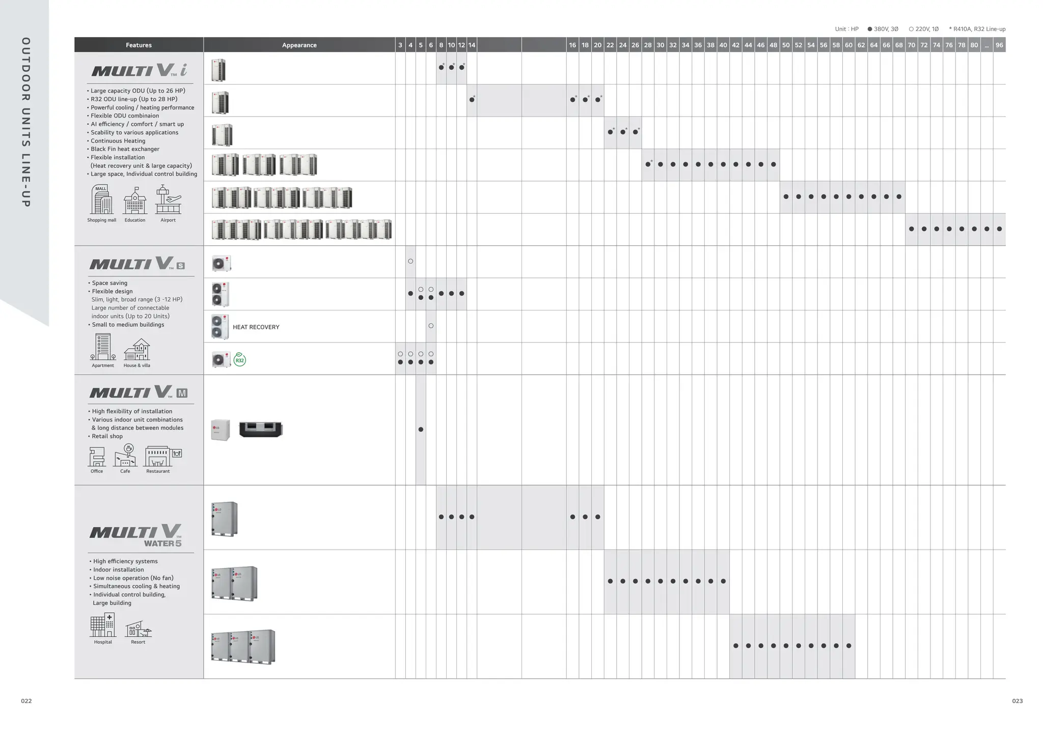
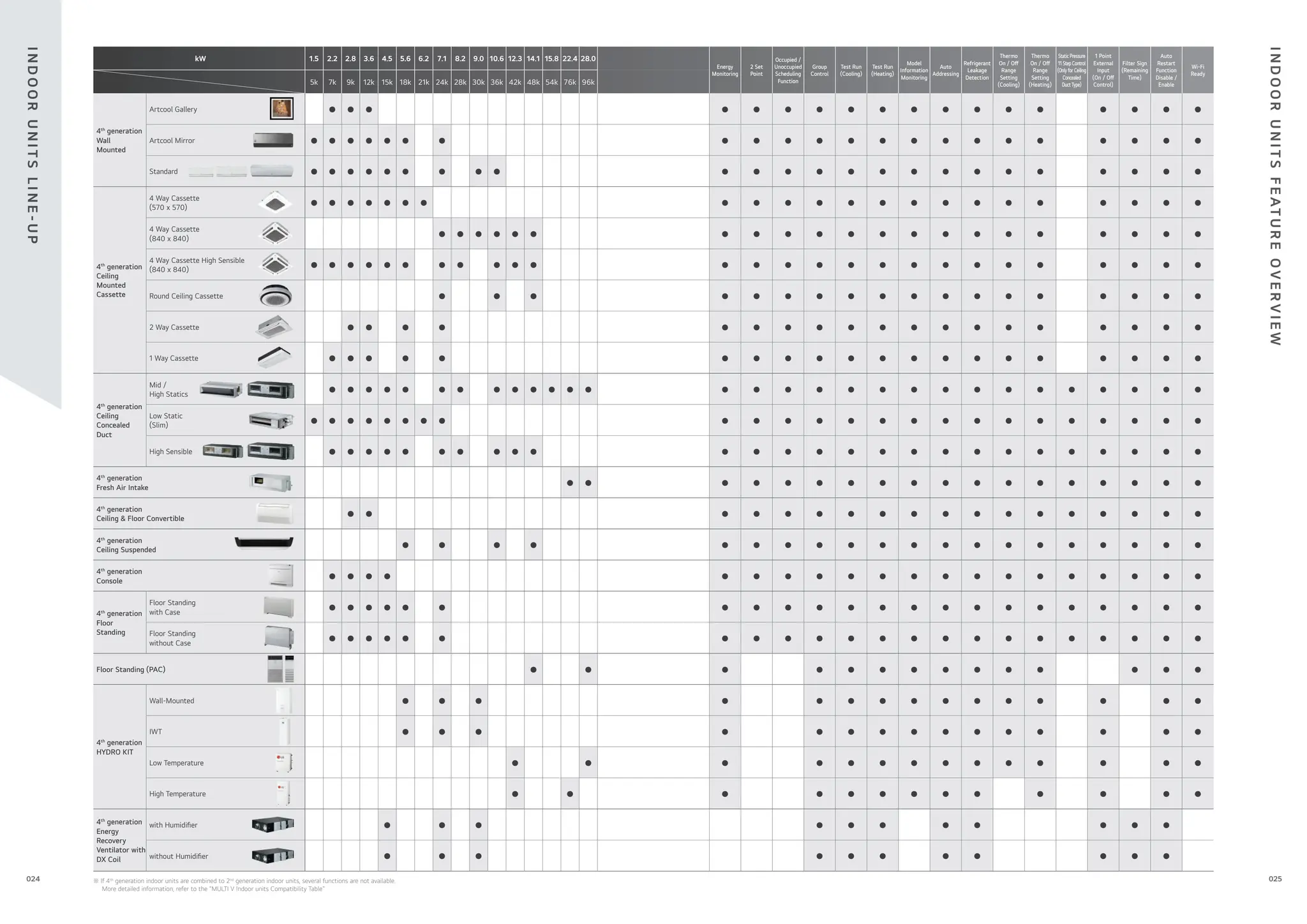


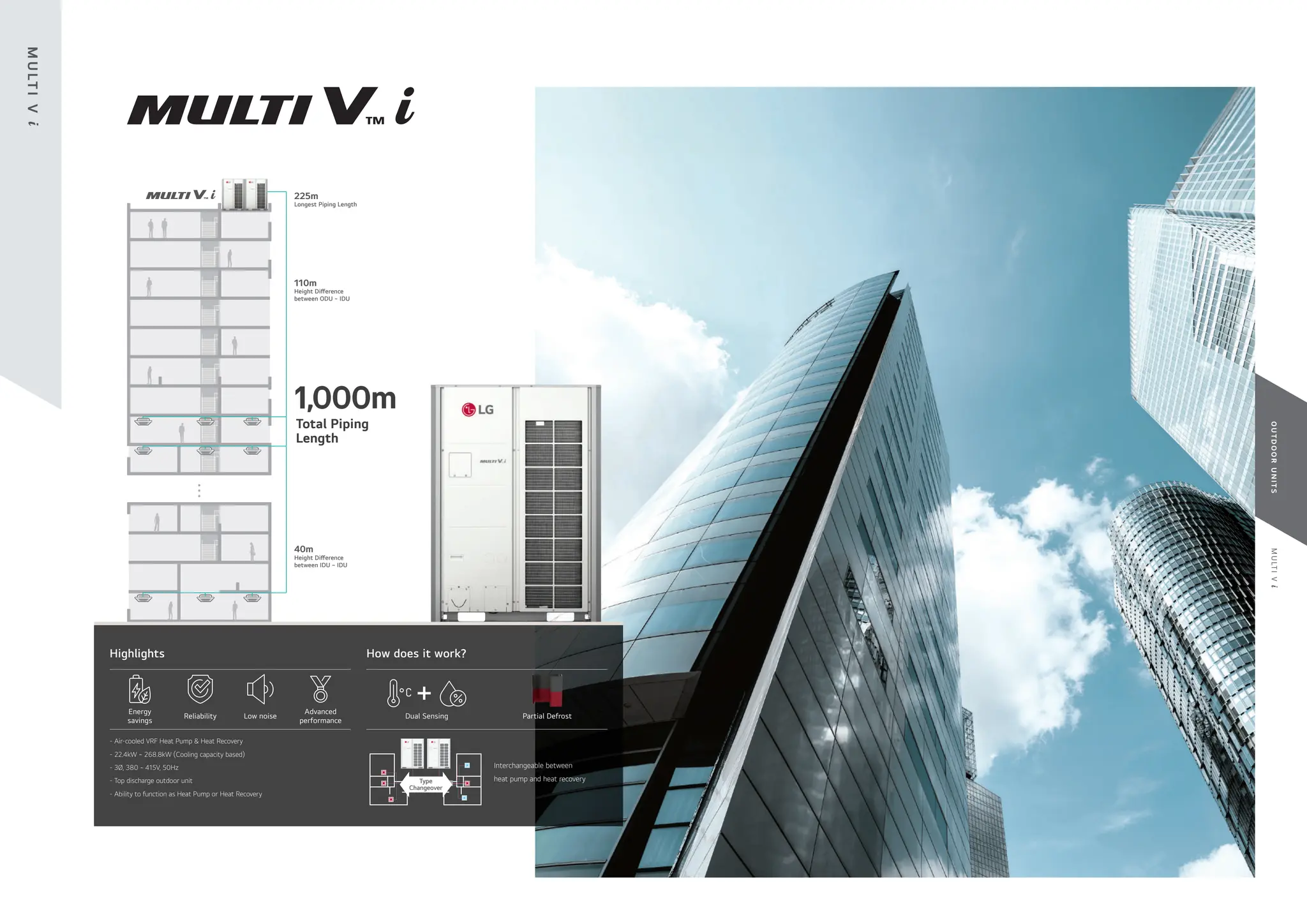
![033
032
M
U
LT
I
V
i
O
U
T
D
O
O
R
U
N
I
T
S
Maximum 26HP for a Single Outdoor Unit
Compact Design with Larger Capacity
LG MULTI V i saves space, time, and installation costs by o ering a larger capacity single outdoor unit.
Lighter outdoor units reduce the installation area and architecture structure, increasing the space for roof gardens.
Install 260HP
A company
23.4 m2
17.5 m2
Installation
Area (m2
)
25 % ↓
(20HP x 13EA) (26HP x 10EA)
A company
4,520 kg
3,620 kg
Total Weight
(kg)
20 % ↓
(20HP x 13EA) (26HP x 10EA)
The Largest
Capacity in 1 Unit
Max. 26HP
Space saving
Time saving
Installation costs saving
Innovative Energy e ciency /
Performance realization
- Maximum 26HP for a Single Outdoor Unit
- Compact Design with Larger Capacity
- Powerful Performance
- Powerful Cooling Performance
- Powerful Heating Performance
- Newly Designed Compact Fan
- Flexible Outdoor Units Combination
- Corrosion Resistant
Recognizes various environments &
optimizes itself through its AI Engine
AI EFFICIENCY UP
- AI Smart Care
- AI Energy Management
AI COMFORT UP
- Adaptive Noise Control
- Noise Target Control
- Weather Information Interlocking Control
AI SMART UP
- AI Smart Diagnosis
- Large Capacity Black Box
- Auto Tuning System
- Remote Upgrade System
Upgrading & evolutionary system according to customer
-LG’s Control Solution
-Smart GUI
-New Innovative Controller
02
03
01
I
N
N
O
VAT
I
V
E
H
I
G
H
L
I
G
H
T
O
F
M
U
LT
I
V
i
A/C
(Air Conditioner)
Valve / Pump
AO (Analog Output)
Fan / Lighting / Switch
DO (Digital Output)
LG AHU
Occupancy Sensor / Alarm / Key-Tag
DI (Digital Input)
Temperature / Humidity
/ CO2 Sensor
AI (Analog Input)
Interlocking
System
※ Previous model: ARUM261LTE5, New model: ARUM260LTE6
※ This scene is designed only for easier understanding, because 26HP unit cannot be applicable.
8,280 mm
[ MULTI V i ]
11,030 mm
[ A company ]
2,750 mm](https://image.slidesharecdn.com/240222lgmultivcataloguelow-251206043823-67e9ad80/75/240222-LG-Multi-V-Catalogue_low-pdffdffdffdwfdfdsfdfewffgegg-17-2048.jpg)
![035
034
M
U
LT
I
V
i
O
U
T
D
O
O
R
U
N
I
T
S
Powerful Cooling Performance
MULTI V 5 has already proved itself highly competitive in the European market in terms of efficiency levels, but MULTI V i exceeded
its predecessor.
Reliable cooling operation up to 52°C, with full performance at 43°C. End users are able to enjoy comfortable indoor environments, even
with extreme weather conditions outside.
Powerful & Stable Cooling Performance
Powerful Performance
[ Better than the Best ]
EER
Max. 15% EER
※ For certain models in the line-up.
※ Final speci cations may change slightly.
Cooling Operation Range -15 ~ 52°C -15 ~ 48°C
Performance at 43°C Full 92 %
Full
performance
at 43°C
Powerful Heating Performance
More reliable heating operation is provided at down to -30°C and full performance at -10°C. Stable heating performance is guaranteed
even in the case of an unexpected outdoor temperature drop.
Stable & Powerful Heating
Heating Performance
※ Final speci cations may change slightly.
※ The defrost process is simpli ed for easier understanding. ※ HEX: Heat Exchanger
Heating Operation Range -30 ~ 16°C -25 ~ 16°C
Performance at -10°C Full 92 %
Full
Performance
at -10°C
Improved design for defrost with an independent HEX system and accumulated freezing prevention design. With a di erentiated structure and design,
it provides longer heating time and reduced defrost time.
Improved design
Full performance at -10°C
7 0 -5 -7 -10 -20 -25 -30
65
60
55
50
45
kW
Temp.
Continuous Heating
The heating operation duration was extended by
independent HEX system for defrosting.
Competitors
0 10 20 30 40 50 60
50
50
40
40
30
30
20
20
Time
(min)
Heating
Defrosting
Heating
Defrosting
(Stop Heating)
NEW Accumulated Freezing Prevention Design
After defrost,
ice is the deposited
on the HEX
IDU Ref. temp.(℃)
Time
(min)
0 10 20 30 40 50 60
Heating
Heating
Heating Heating
IDU Ref. temp.(℃) After defrost,
less ice is the
deposited
on the HEX
Preventing the freezing of the lower part of the heat
exchanger
Competitors
Indoor outlet air temperature deviation
during heating minimum load operation
70%
1
2
3
Defrost Time
Reduction
65%
Continuous Heating
1
I
N
N
O
VAT
I
V
E
I
N
N
O
VAT
I
V
E
2 3](https://image.slidesharecdn.com/240222lgmultivcataloguelow-251206043823-67e9ad80/75/240222-LG-Multi-V-Catalogue_low-pdffdffdffdwfdfdsfdfewffgegg-18-2048.jpg)


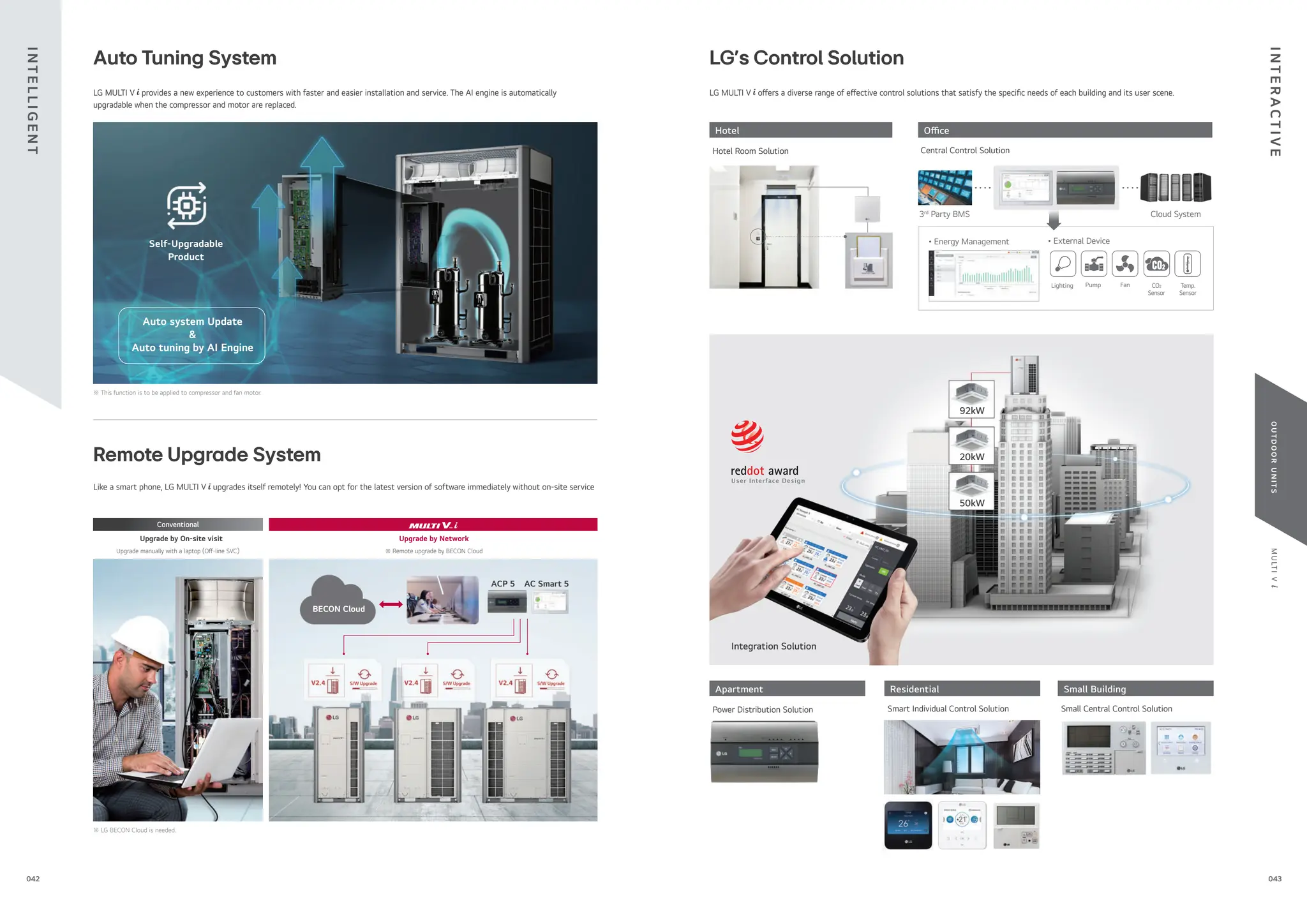

![047
046
M
U
LT
I
V
i
O
U
T
D
O
O
R
U
N
I
T
S
Cooling / Heating Operation
Note
1. These gures assume the following operating conditions
: Equivalent piping length is standard condition, and level di erenc is 0m.
2. Range of pull down operation: If the relative humidity is too high, cooling capacity can
be decreased by the sensible heat reduction.
3. Warming up operation means that the outdoor (outside) unit operates to reach the
range of continuous operating, however it may not operate continuously due to safety
or protection logic.
Outdoor Temperature (°C DB)
Cooling
Outdoor Temperature (°C WB)
Heating
1.9.2 Heating
1.9.1 Cooling
30°C
Indoor Temperature (°C DB)
Range
for
warming
up
operation
10°C
-20°C
-10°C
-15°C
-25°C
-30°C
-5°C
0°C
5°C
10°C
15°C
18°C
20°C
15°C 20°C 25°C 27°C
Range
for
continuous
operation
30°C
Indoor Temperature (°C WB)
10°C
-5°C
-10°C
-15°C
10°C
0°C
20°C
15°C
5°C
25°C
30°C
40°C
35°C
45°C
50°C
48°C
52°C
55°C
15°C 20°C 25°C 27°C
14°C
1.9.2 Heating
1.9.1 Cooling
Range
for
continuous
operation
Range
for
pull
down
operation
Simultaneous Cooling / Heating Operation
Outdoor Temperature (°C DB)
Cooling
Outdoor Temperature (°C WB)
Heating
Indoor Temperature (°C WB)
Range
for
continuous
operation
-5°C
-10°C
-15°C
10°C
0°C
25°C
20°C
15°C
5°C
27°C
30°C
Range
for
pull
down
operation
10°C 14°C 15°C 20°C 25°C 27°C 30°C
Note
1. These gures assume the following operating conditions
: Equivalent piping length is standard condition, and level di erenc is 0m.
2. Range of pull down operation: If the relative humidity is too high, cooling capacity can
be decreased by the sensible heat reduction.
3. Warming up operation means that the outdoor (outside) unit operates to reach the
range of continuous operating, however it may not operate continuously due to safety
or protection logic.
20°C
16°C
15°C
10°C
5°C
0°C
-5°C
-10°C
Indoor Temperature (°C DB)
Range
for
pull
down
operation
Range
for
continuous
operation
10°C 15°C 20°C 27°C 30°C
ARUM080LTE6 / ARUM100LTE6
ARUM120LTE6
[Unit : mm]
No. Part Name Description
1 Leakage test hole (Side) Ø22.2
2 Wire routing hole (Front) 2-Ø30
3 Wire routing hole (Bottom) 2-Ø22.2
4 Power cord routing hole (Front) 2-Ø45
5 Power cord routing hole (Bottom) 2-Ø50
6 Pipe routing hole (Front) -
7 Pipe routing hole (Bottom) -
3D View
(Pitch
of
foundation
bolt
holes)
(Pitch of foundation bolt holes)
Airguide fastening total 12 places
(Refer to the hole on the Airguide
for the fastening position.)
165
141
92
129 159
537
72 72
490
760
405
350
300
105 730
930
159
106
127
163
220
826
1,745
174
731
99
74
T
E
C
H
N
I
C
A
L
D
ATA
T
E
C
H
N
I
C
A
L
D
ATA
Nomenclature
ARU M L
100 T E 6
Serial number
E: High E ciency
Air Discharge Type
T : Top Discharge
Electrical Ratings
L : 3Ø, 380 ~ 415 V, 50Hz
Total Cooling capacity in Horse Power(HP) unit
EX) 8HP → ‘080’, 10HP → ‘100’
Combination of Inverter Type and Cooling Only,
Heat Pump or Heat Recovery
M : Inverter, Heat Pump and Heat Recovery
MULTI V System with Indoor Unit using R410A
ARU : Global line-up
Position of Sound Pressure Level Measuring
• Data is valid at di use eld condition.
• Data is valid at nominal operating condition.
• Reference accoustic pressure 0dB = 20μPa.
• Sound pressure level is measured on the rated condition in
the anechoic rooms by ISO 3745 standard. Refer to the model
speci cations for nominal conditions (Power source and Ambient
temperature, etc).
• Sound levels can be increased in accordance with installation and
operating conditions. (Operating conditions include some functional
condition like Static pressure mode, air guide use, Room target
temperature setting, etc and these functions are di erent in
accordance with each model).
• Sound level will vary depending on a range of factors such as the
construction (acoustic absorption coe cient) of particular room in
which the equipment in installed.
O : Applied, X : Not applied
- Accessory : Ordered and purchased separately the accessory package referring to
the model name provided and install at eld.
- Accessory line-ups varies by region, so check your local catalogue or local sales
material
Outdoor Units Function
Category Functions Value
Reliability
Defrost / Deicing ○
High Pressure Switch ○
Phase Protection ○
Restart Delay (3-minutes) ○
Self Diagnosis ○
Soft Start ○
Compressor Balanced Operation ○
Convenience
Test Function ○
Night Low Noise Operation ○
Peak Control ○
Mode Lock ○
SLC (Smart Load Control) ○
Linear Bypass Cycle ○
Noise Target Control ○
Weather Information
Interlocking Control
○
Special Functions
Comfort Cooling ○
ODU Dry Contact Function ○
High Static Pressure Compensation ○
Continuous Cooling ○
Continuous Heating (Partial Defrost) ○
Convenient Energy Check ○
Automatic Tuning Upgrade ○
Remote Software Upgrade ○
AI Smart Care ○
AI Indoor Space Care ○
AI Energy Target Control ○
AI Smart Diagnosis ○](https://image.slidesharecdn.com/240222lgmultivcataloguelow-251206043823-67e9ad80/75/240222-LG-Multi-V-Catalogue_low-pdffdffdffdwfdfdsfdfewffgegg-24-2048.jpg)
![049
048
M
U
LT
I
V
i
O
U
T
D
O
O
R
U
N
I
T
S
[Unit : mm]
ARUM140LTE6 / ARUM160LTE6
ARUM180LTE6 / ARUM200LTE6
No. Part Name Description
1 Leakage test hole (Side) Ø22.2
2 Wire routing hole (Front) 2-Ø30
3 Wire routing hole (Bottom) 2-Ø22.2
4 Power cord routing hole (Front) 2-Ø45
5 Power cord routing hole (Bottom) 2-Ø50
6 Pipe routing hole (Front) -
7 Pipe routing hole (Bottom) -
3D View
Airguide fastening total 12 places
(Refer to the hole on the Airguide
for the fastening position.)
(Pitch
of
foundation
bolt
holes)
(Pitch of foundation bolt holes)
105
148
223
270
320
374
166
140
92
163
220
615
1,745
127
129
699
1,240
159 159 72
517
760
72
106
731
1,040
ARUM220LTE6 / ARUM240LTE6
ARUM260LTE6
[Unit : mm]
No. Part Name Description
1 Pipe routing hole (Bottom) -
2 Pipe routing hole (Front) -
3 Power cord routing hole (Front) 2-Ø30
4 Wire routing hole (Front) 2-Ø45
3D View
(Pitch
of
foundation
bolt
holes)
(Pitch of foundation bolt holes)
Airguide fastening total 12 places
(Refer to the hole on the Airguide
for the fastening position.)
500
816
981
1,026
1,096
1,640
159 72 72
442
760
722
619
533
105 1,438
1,056
162
92
818
1,745
126
219
183
731
80
T
E
C
H
N
I
C
A
L
D
ATA
T
E
C
H
N
I
C
A
L
D
ATA](https://image.slidesharecdn.com/240222lgmultivcataloguelow-251206043823-67e9ad80/75/240222-LG-Multi-V-Catalogue_low-pdffdffdffdwfdfdsfdfewffgegg-25-2048.jpg)
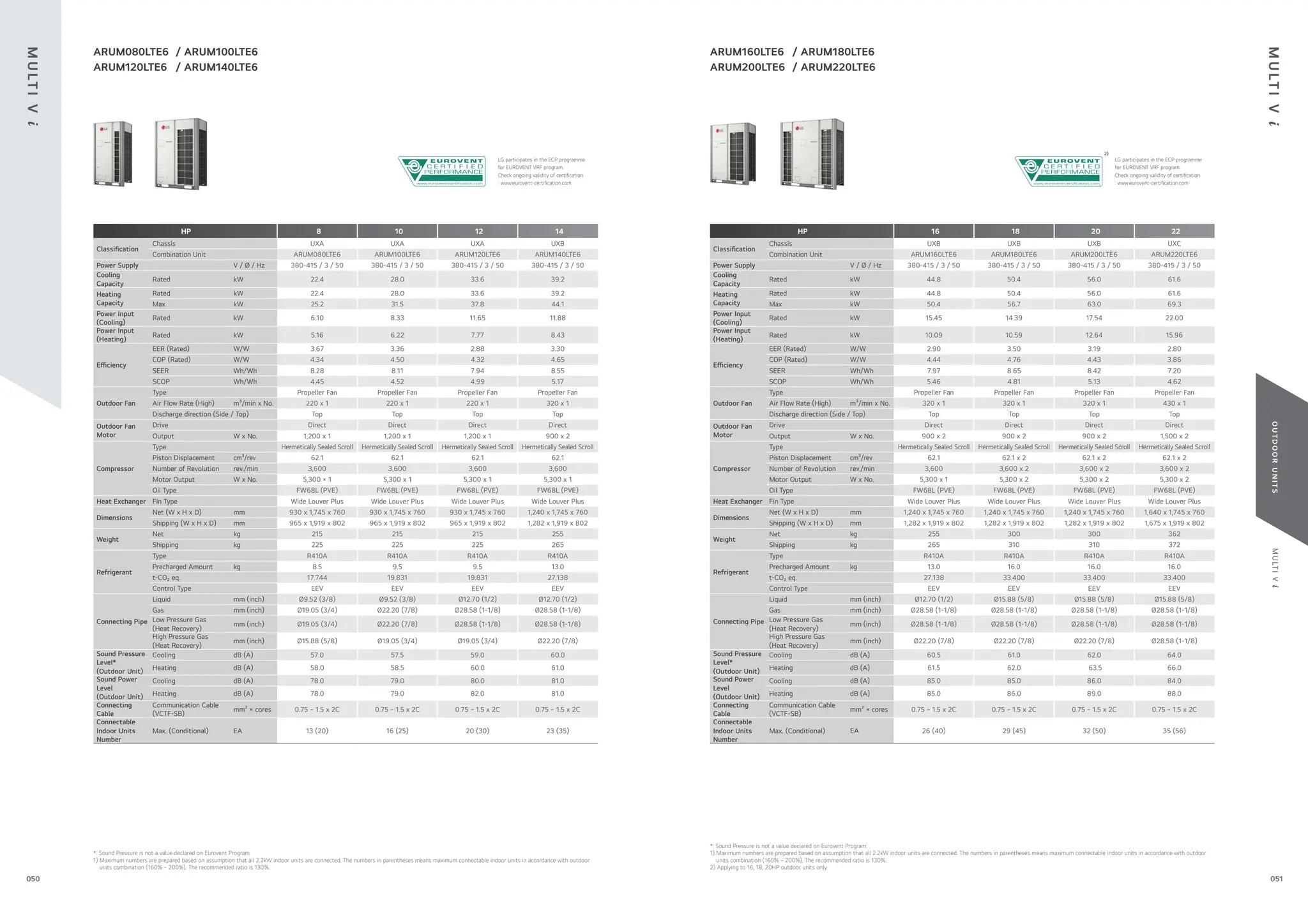


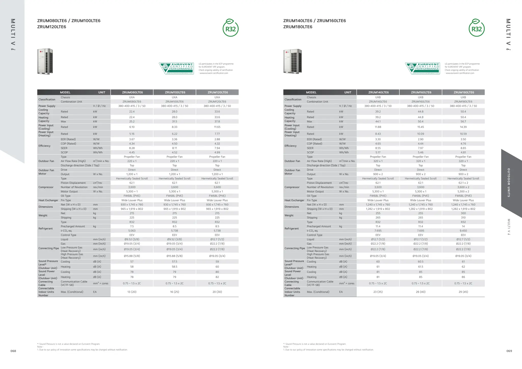
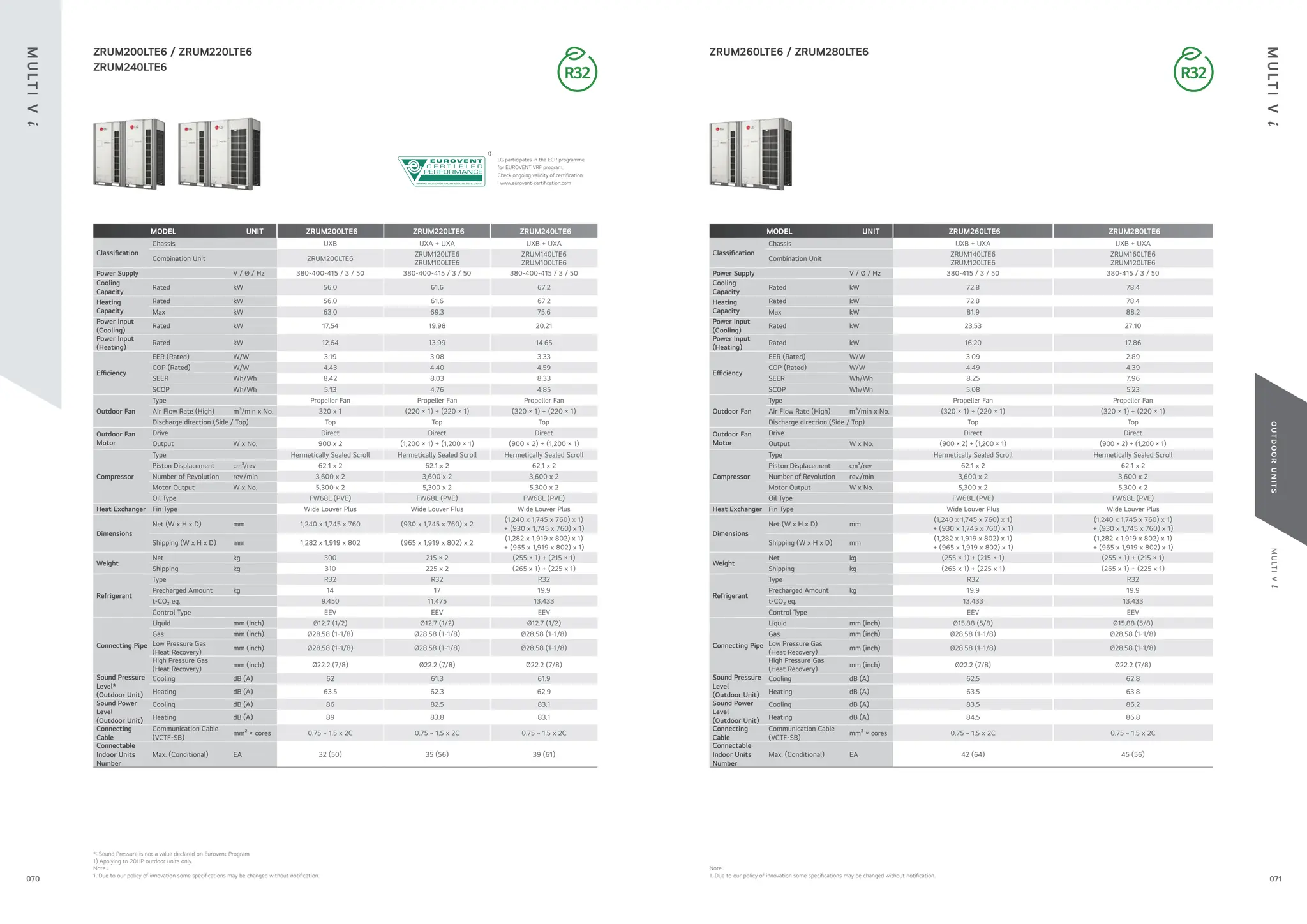
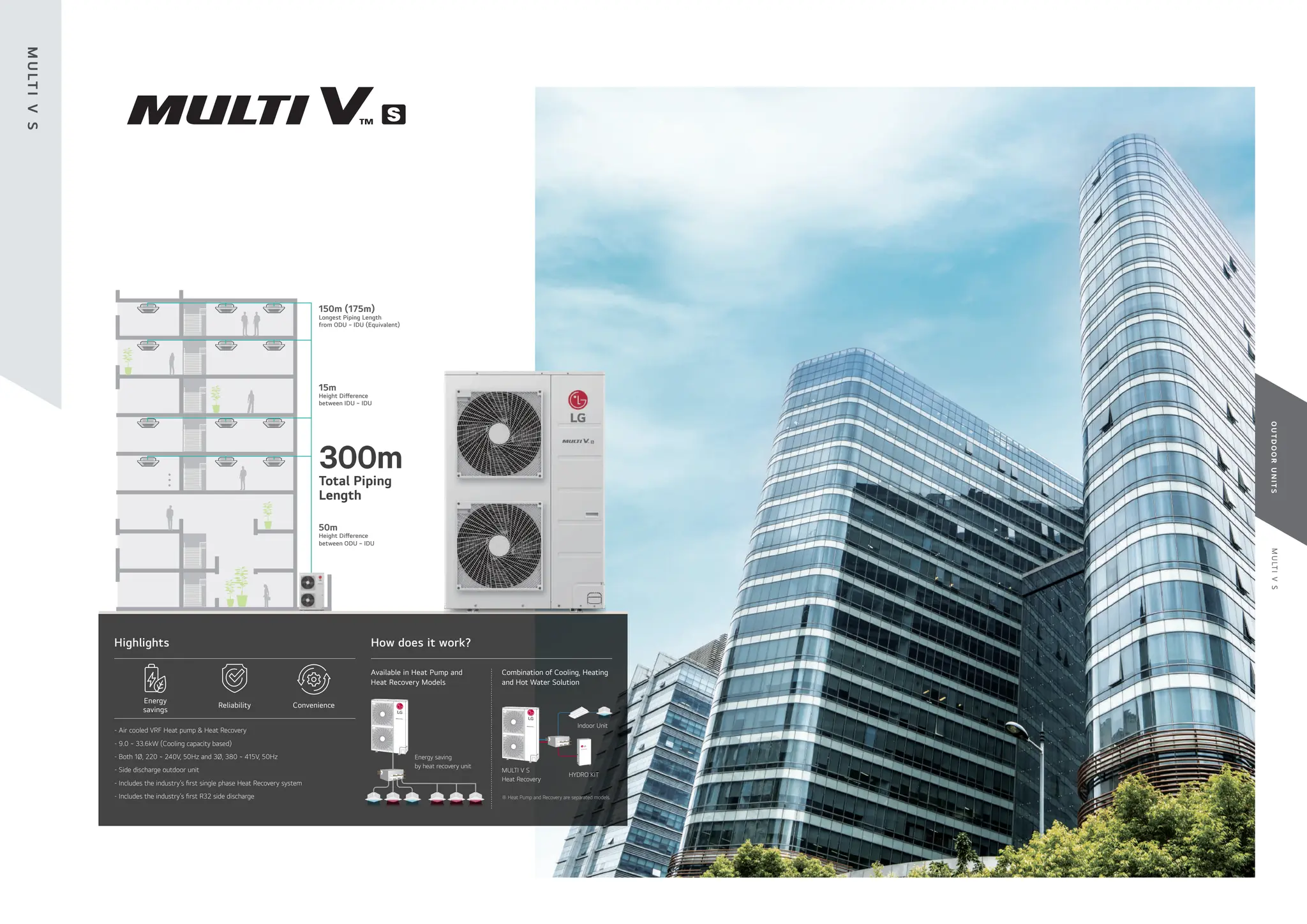

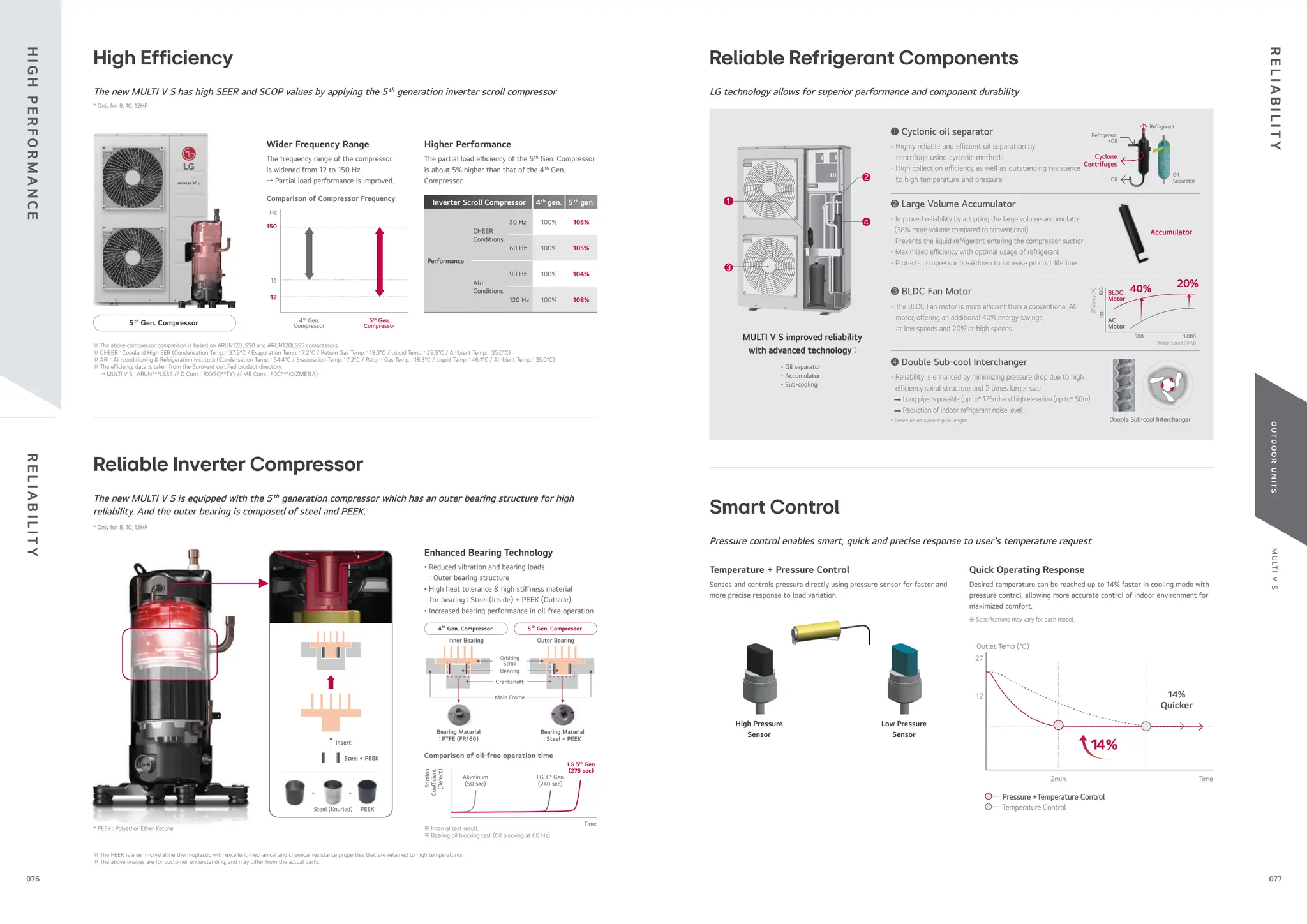

![M
U
LT
I
V
S
O
U
T
D
O
O
R
U
N
I
T
S
94
25
52
80
2
291
276
111
40
91
250
164
416
695
5-1.D. Ø
20 holes for drain connection
606
52
80
25
96
23
1,380
1 6
2
5
330 26
4 holes for Anchor Bolts (M10)
620
390
360
14
Piping
Direction
Low Noise Operation
Decreased noise during operation with low noise functionality
At night low noise mode, the noise level can reduce up to 14% in comparison with normal operation mode.
※ Normal mode noise level (28kw) : 58dB(A)
※ Night 3 step noise level (28kw) :
56dB(A),53dB(A), 50dB(A)
※ Sound pressure tested by following
conditions : 1m distance / 1.5m height
50dB(A)
Max
58dB(A)
Day Night
58
50
Mode Start
58
Step 1
56
Step 2
53
Step 3
50
Capacity
Mode End
Load
Sound Level
8:00 12:00 16:00 20:00 0:00 4:00 8:00 12:00 16:00
Time
Night
Upgraded Fault Detection and Diagnosis
Easy and convenient maintenance with self-diagnosis
The inclusion of FDD elements - Auto start-up, auto refrigerant check, black box
functionality, simultaneous evaluation, and auto refrigerant collection, provides the optimal
solution for user reliability and ease of maintenance.
- Auto commissioning mode
- Auto refrigerant collection
- Auto evaluation of refrigerant amount and charging
- Able to access LGMV (LG Monitoring View) by smartphone
- Black box function
- Piping & wiring error check-up
- FDD (Fault Detection and Diagnosis)
FDD
MICOM
B
Serial number
Model Type
S : Standard
L : Compact
Air Discharge Type
S : Side Discharge
Electrical Ratings
L : 3Ø, 380-415V, 50Hz
G : 1Ø, 220-240V, 50Hz
Total Cooling Capacity in Horse Power(HP) unit
EX) 8HP → '080', 10HP → '100'
Combination of Inverter Type and Cooling Only
or Heat Pump
N : Inverter and H/P, V : Inverter and C/O
MULTI V System Outdoor Unit using R410A
Outdoor Units Function
Category Functions MULTI V S
Key Refrigerant
Components
Variable Path of Outdoor Unit HEX -
HiPORTM
(High Pressure Oil Return)
-
Humidity Sensor ARUB060GSS4 only
Corrosion Resistance Black Fin ○
Oil Sensor -
Special Function
Dual Sensing ARUB060GSS4 only
Low Noise Operation ○
Hgih Static Mode of Outdoor
Unit Fan
○
Partial Defrosting -
Auto Dust Removal of Outdoor
Unit
(Fan reverse rotation)
-
Indoor Cooling Comfort Mode
Based Outdoor Temperature
○
Smart Load Control (SLC)
(Changing indoor discharge air
temperature according to load)
○
Outdoor Unit Control Refer to
Humidity
ARUB060GSS4 only
Basic Function
Defrost / Deicing ○
High Pressure Switch ○
Phase Protection ○
Restart Delay (3-minutes) ○
Self Diagnosis ○
Soft Start ○
Test Run Function -
Central Controller
AC Ez (Simple Controller) PQCSZ250S0
AC Ez Touch PACEZA000
AC Smart IV PACS4B000
AC Smart 5 PACS5A000
ACP (Advanced Control Platform)
IV
PACP4B000
ACP (Advanced Control Platform)
5
PACP5A000
AC Manager 5 PACM5A000
BNU (Building
Network Unit)
ACP5 (w U60FT) ○
ACP BACnet PQNFB17C0
IO Module (ODU Dry Contact) PVDSMN000
PDI (Power
Distribution
Indicator)
Standard PPWRDB000
Premium PQNUD1S40
Cool / Heat Selector PRDSBM
Cycle Monitoring
Device
LGMV PRCTIL0
Mobile LGMV PLGMVW100
Additional kit
Refrigerant Charging Kit
○
(Logical operation)
Not applied to
ARUB060GSS4
Low Ambient Kit -
Variable Water Flow Valve Control
Kit
-
Note
1. Unit should be installed in compliance with the
installation manual in the product box.
2. Unit should be grounded in accordance with the
local regulation or applicable national codes.
3. All electrical components and materials to be
supplied from the site must comply with the
local regulations or international codes.
4. Electrical characteristics chapter should be
considered for electrical work and design.
Especially the power cable and circuit breaker
should be selected in accordance with that.
No. Part Name Description
1 Air Outlet -
2 Power and communication cable Hole -
3 Gas Pipe Connection Welding joint
4 Liquid Pipe Connection Welding joint
5 Handle -
6 Pipe routing hole (front) -
7 Pipe routing hole (side) -
8 Pipe routing hole (back) -
[Unit : mm]
[Unit : mm]
Symbols
Piping Direction
Datum Iine
A
390
627
834
291
1
1
1
276
660
476
24
83
141
466
A
A
C
A
B B
C
360
165
(7) 81 26
26
40
91
250 696
416
97
51
64
82 244
148
(34)
620
950
330
4 holes for Anchor Bolts (M10)
5-1.D. Ø20 holes for drain connection
Piping
Direction
5 5
5 5
1 2
3
4
3D View
Nomenclature ARUN040GSS0
ARUN080LSS5
ARU N L
100 S S 0
※ ○ : Applied, - : Not Applied
Heating Priority
MULTI V S provides hot water during the cooling season with a heating priority function which automatically changes operation modes
when hot water is required.
I
M
P
R
O
V
E
D
U
S
E
R
C
O
N
V
E
N
I
E
N
C
E
T
E
C
H
N
I
C
A
L
D
ATA
※ This function is available only when the dip switch of the outdoor unit and wired remote controller of the indoor unit & hydro kit are set.
(ODU : Dip Switch No.5 On → Fn25 → Heat → On) // (IDU : Installer Setting → ODU Cycle Priority → Stand-by) // (Hydro Kit : Installer Setting → ODU Cycle Priority → Heat)
※ The above images are for customer understanding.
536
24
91
42
44
60
81
94
25
75
52
85
606
557
3
4
8
2
Piping connection port
3D View
(Heat Pump)
Y-branch
Sequence of Heating Priority
When hot water is required.
Heating Priorty
Hydro Kit
When hot water is not required.
Indoor Unit
Cooling
Hot Water
Cooling
Cooling
Stand-by
Cooling
Stand-by
Heating
EEV
Closed
Automatic
Change
081
080](https://image.slidesharecdn.com/240222lgmultivcataloguelow-251206043823-67e9ad80/75/240222-LG-Multi-V-Catalogue_low-pdffdffdffdwfdfdsfdfewffgegg-41-2048.jpg)


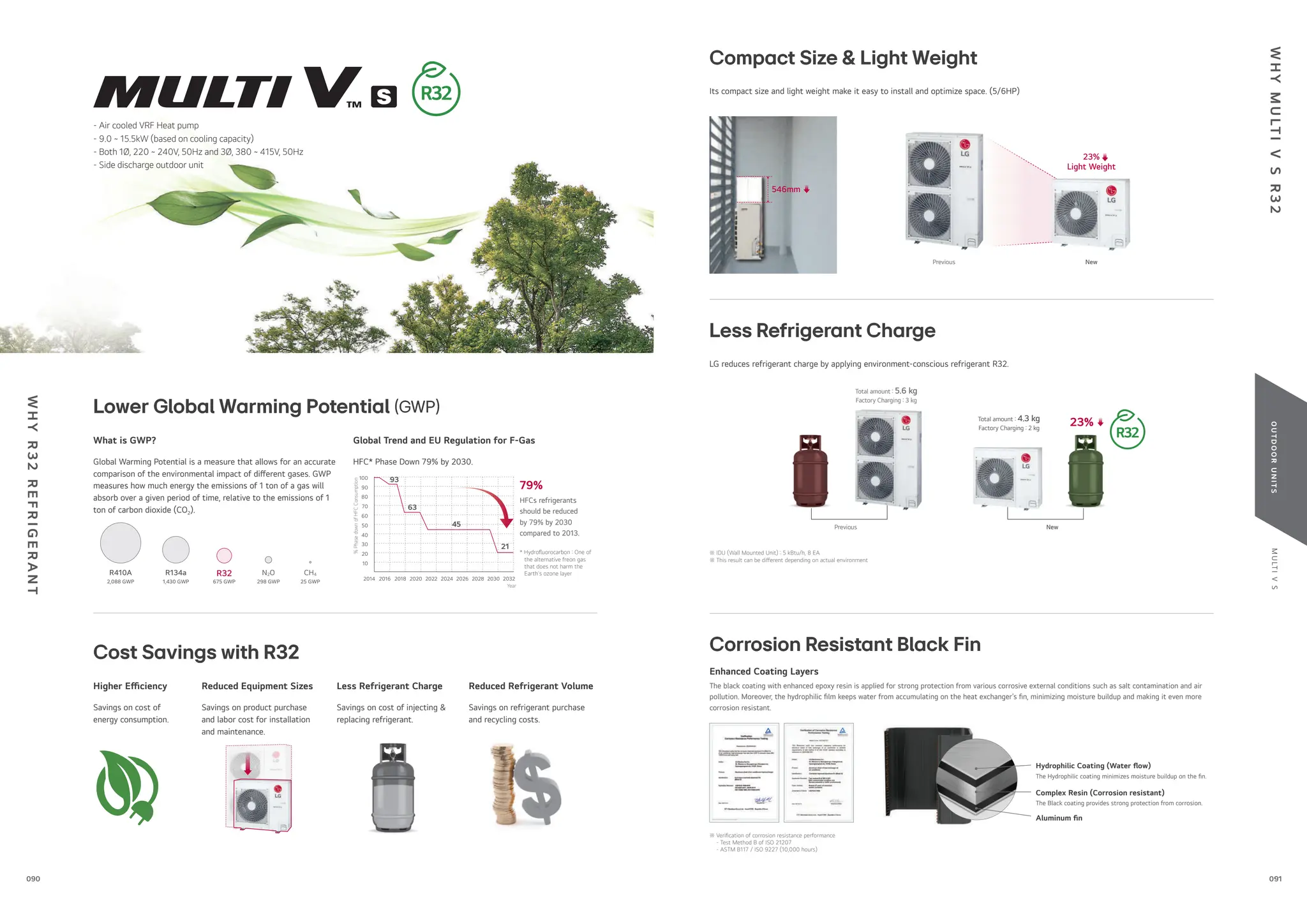


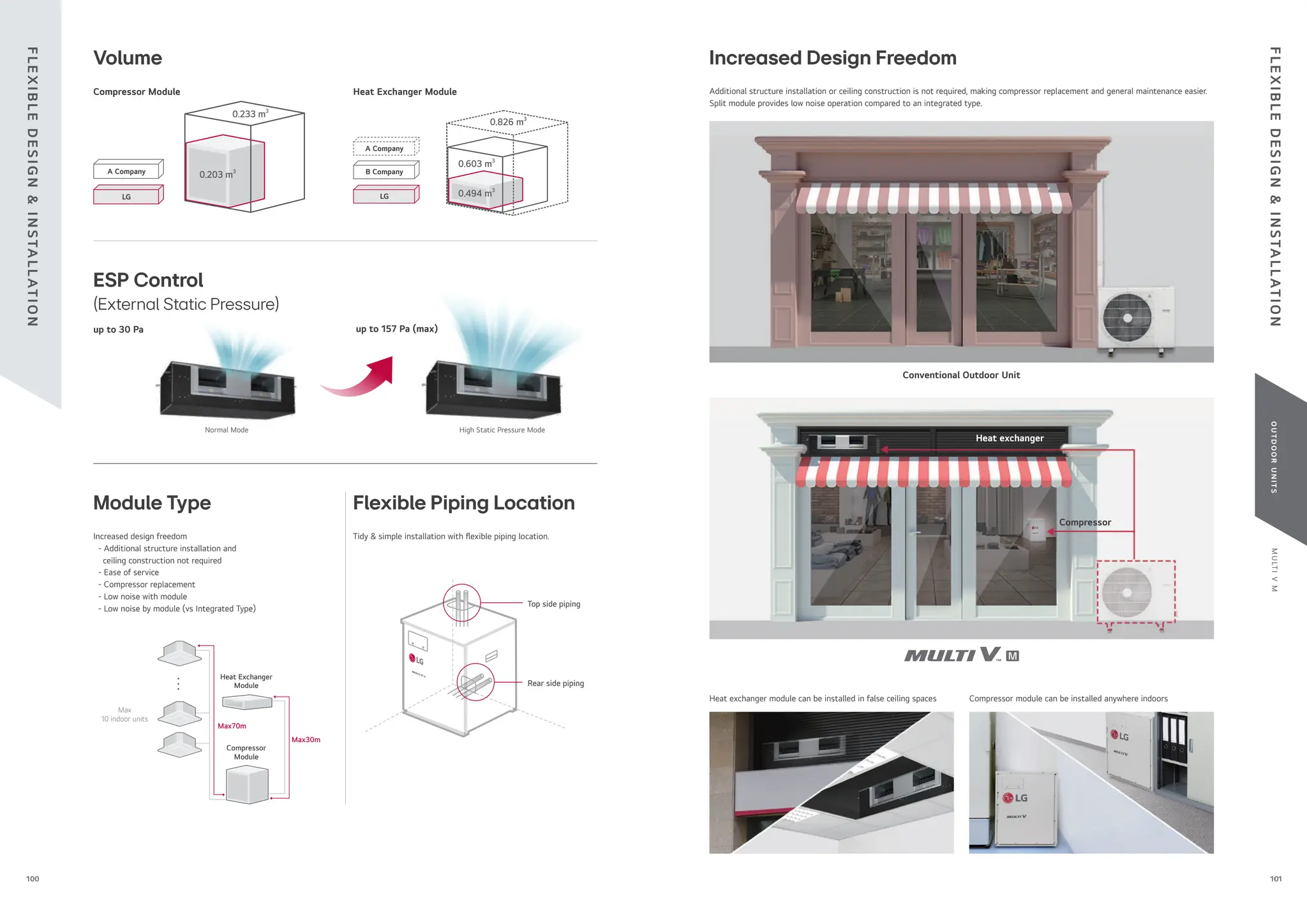
![M
U
LT
I
V
M
O
U
T
D
O
O
R
U
N
I
T
S
Indoor Temperature (°C WB)
Range
for
continuous
operation
Outdoor
Temperature
(°C
DB)
10°C
-10°C
5°C
-5°C
15°C
10°C
0°C
20°C
25°C
30°C
35°C
40°C
43°C
45°C
15°C 20°C 25°C 27°C 30°C
14°C
Range
for
pull
down
operation
Heat Pump
Cooling
Indoor Temperature (°C DB)
Range
for
warming
up
operation
Range
for
continuous
operation
Outdoor
Temperature
(°C
WB)
10°C
-25°C
-10°C
-20°C
5°C
0°C
-5°C
-15°C
10°C
15°C
18°C
20°C
15°C 20°C 25°C 27°C 30°C
Heating
[Unit : mm]
3D View
30
150
122
C
A
B
D
36 110
580
249
15
Ø15
249
Left
Detail D
Front Right
327
530
101
216
512
19
19
25 25
462
22.5
7.5
512
352
700
500
[Unit : mm]
462
300
29 28 69 335
221 219 551
555
625
1389
388
22
95
113
1122
1562
335
111
242
170
292
314
393
352
352
352
352
357
222
294
560
19
19
1681
1622
1397
850
Outdoor Units Function
Category Functions Modular
Key Refrigerant
Components
Variable Path of Outdoor Unit HEX -
HiPORTM
(High Pressure Oil Return) -
Humidity Sensor -
Corrosion Resistance Black Fin ○
Oil Sensor -
Useful Function
Dual Sensing -
Low Noise Operation ○
Hgih Static Mode of Outdoor Unit
Fan
○
Partial Defrosting -
Auto Dust Cleaning of Outdoor Unit
(Fan reverse rotation)
-
Indoor Cooling Comfort Mode Based
Outdoor Temperature
○
Smart Load Control (SLC)
(Changing indoor discharge air
temperature according to load)
○
Outdoor Unit Control Refer to
Humidity
-
Reliability
Defrost / Deicing ○
High Pressure Switch ○
Phase Protection ○
Restart Delay (3-minutes) ○
Self Diagnosis ○
Soft Start ○
Test Run Function -
Central Controller
AC Ez (Simple Controller) PQCSZ250S0
AC Ez Touch PACEZA000
AC Smart IV PACS4B000
AC Smart 5 PACS5A000
ACP (Advanced Control Platform) IV PACP4B000
ACP (Advanced Control Platform) 5 PACP5A000
AC Manager 5 PACM5A000
BNU (Building
Network Unit)
ACP5 (w U60FT) ○
ACP BACnet PQNFB17C0
Installation
Refrigerant Charging Kit -
Variable Water Flow Valve Control Kit -
PDI (Power
Distribution Indicator)
Standard -
Premium -
Cool / Heat Selector PRDSBM
Low Ambient Kit -
IO Module
(ODU Dry Contact)
PVDSMN000
Cycle Monitoring
Device
LGMV PRCTIL0
Mobile LGMV PLGMVW100
Nomenclature Compressor Module
Heat Exchanger Module
ARU N L
050 M S 0
Serial number
Model Type
S : Set
C : Compressor Module
E : Heat Exchanger Module
Outdoor unit Type
M : Modular Type
Electrical Ratings
L : 3Ø, 380-415V, 50Hz
G : 1Ø, 220-240V, 50Hz
Total Cooling Capacity in Horse Power (HP) unit
EX) 5HP → '050', 8HP → '080'
Combination of Inverter Type and Cooling Only
or Heat Pump
N: Inverter and H/P, V: Inverter and C/O
MULTI V System Outdoor Unit using R410A
※ ○ : Applied, - : Not Applied
Installation Space for Compressor Module
Installation Space for Compressor Module
Position of Sound Pressure Level Measuring
Compressor Module Heat Exchanger Module
Category Mark Description Installation Space (mm)
Compressor
Module
a Right 10 or More
b Left 10 or More
c Rear 10 or More
d Front 500 or More
e Top 200 or More
11.1 Sound Pressure Level
[Compressor Module] [Heat Exchanger Module]
11.1 Sound Pressure Level
[Compressor Module] [Heat Exchanger Module]
Top View Front View
Top View Front View
Installation Space for Compressor Module
Installation Space for Heat Exchanger Module
Category Mark Description Installation Space
[ mm ]
Compressor
Module
e
r
o
m
r
o
0
1
t
h
g
i
R
a
e
r
o
m
r
o
0
1
t
f
e
L
b
e
r
o
m
r
o
0
1
r
a
e
R
c
e
r
o
m
r
o
0
0
5
t
n
o
r
F
d
e
r
o
m
r
o
0
0
2
p
o
T
e
Top View Front View
[Unit: mm]
[Unit: mm]
Top View
Front View
※ Measuring place : Anechoic chamber ※ Measuring place : Anechoic chamber
e
Installation Space for Compressor Module
Installation Space for Heat Exchanger Module
Category Mark Description Installation Space
[ mm ]
Compressor
Module
e
r
o
m
r
o
0
1
t
h
g
i
R
a
e
r
o
m
r
o
0
1
t
f
e
L
b
e
r
o
m
r
o
0
1
r
a
e
R
c
e
r
o
m
r
o
0
0
5
t
n
o
r
F
d
e
r
o
m
r
o
0
0
2
p
o
T
e
Top View Front View
[Unit: mm]
[Unit: mm]
Top View
Front View
a
b
c
d
Front Side
Service Space
(Front Side)
Microphone
1.5 m
1.0 m
Installation Space for Compressor Module
Installation Space for Heat Exchanger Module
Category Mark Description Installation Space
[ mm ]
Compressor
Module
e
r
o
m
r
o
0
1
t
h
g
i
R
a
e
r
o
m
r
o
0
1
t
f
e
L
b
e
r
o
m
r
o
0
1
r
a
e
R
c
e
r
o
m
r
o
0
0
5
t
n
o
r
F
d
e
r
o
m
r
o
0
0
2
p
o
T
e
Top View Front View
[Unit: mm]
[Unit: mm]
Top View
Front View
[Unit : mm]
10
or
More
H = 100 or More
Installation Space for Compressor Module
Installation Space for Heat Exchanger Module
Category Mark Description Installation Space
[ mm ]
Compressor
Module
e
r
o
m
r
o
0
1
t
h
g
i
R
a
e
r
o
m
r
o
0
1
t
f
e
L
b
e
r
o
m
r
o
0
1
r
a
e
R
c
e
r
o
m
r
o
0
0
5
t
n
o
r
F
d
e
r
o
m
r
o
0
0
2
p
o
T
e
Top View Front View
[Unit: mm]
[Unit: mm]
Top View
Front View
[Unit : mm]
Air Suction
Air Discharge
600 x 600
(Service Inspection Hole)
70 or More 600 or More
2 m 2 m
1.5 m
DUCT
DISCHARE SUCTION
DUCT
T
E
C
H
N
I
C
A
L
D
ATA
T
E
C
H
N
I
C
A
L
D
ATA
103
102](https://image.slidesharecdn.com/240222lgmultivcataloguelow-251206043823-67e9ad80/75/240222-LG-Multi-V-Catalogue_low-pdffdffdffdwfdfdsfdfewffgegg-52-2048.jpg)
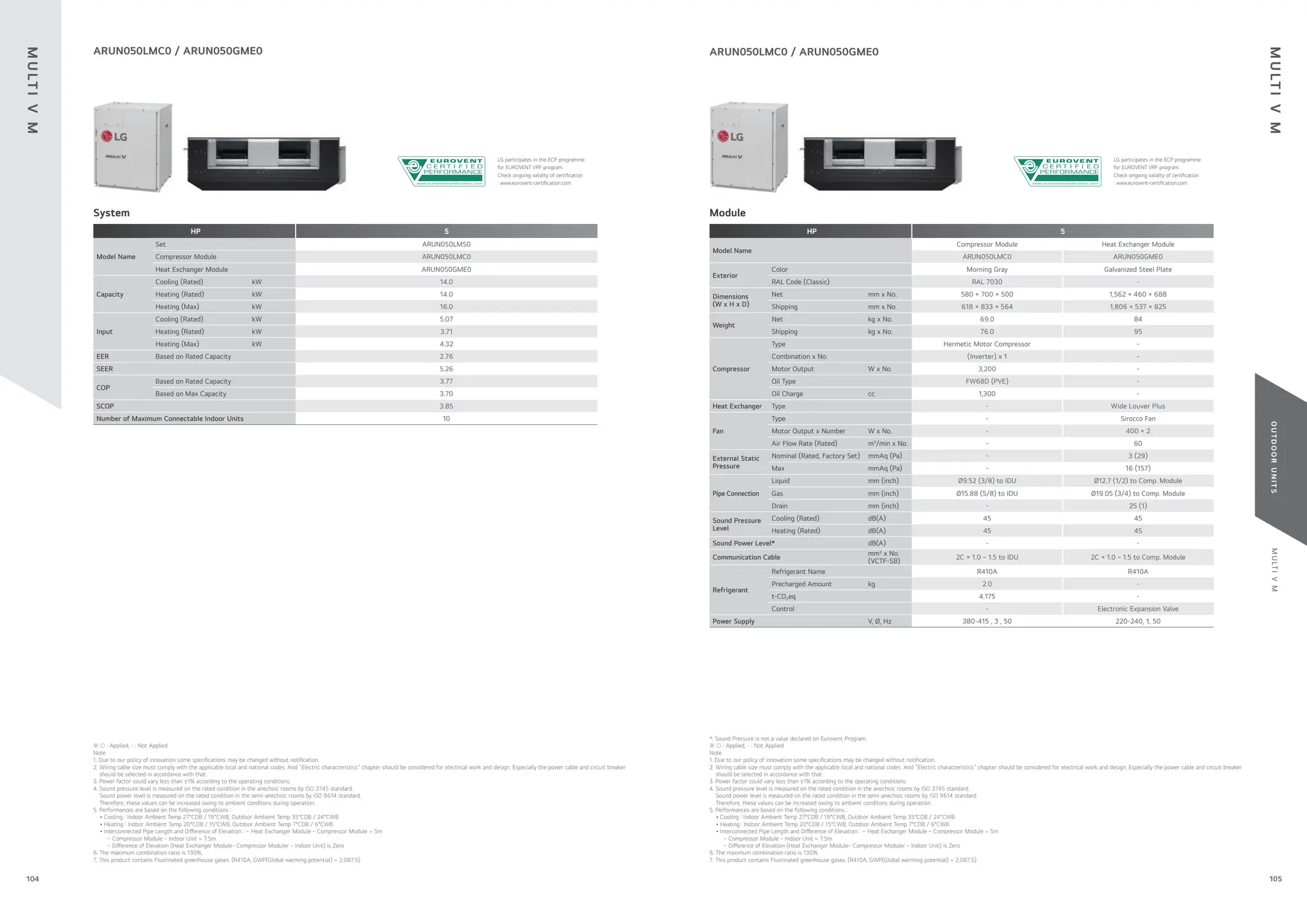

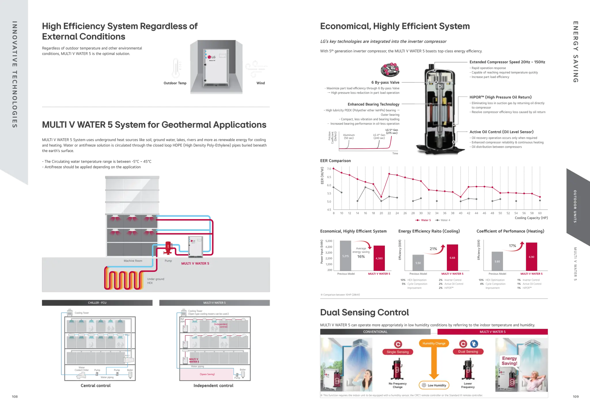
![M
U
LT
I
V
WAT
E
R
5
O
U
T
D
O
O
R
U
N
I
T
S
111
110
Fan
Control Box
Refrigerant-Cooling
Heat Sink
Inverter
Pump
Variable Water
Flow Control Valve
Cooling Tower
DC 0 ~ 10V
PWFCKN000
River / Sea
Geothermal
Note
1. Location : Paris, France
2. O ce, 68,000m2
3. Operation time : 1,344 hours (Cooling period)
Total
Water
Flow
(m
3
)
Total
Water
Flow
(m
3
)
Variable Water Flow
Inverter Pump
Constant Water Flow
Constant Pump
15,456
4,439
1,653,093
71%
36%
1) Inverter pump with MULTI V Water and variable water ow control kit
2) Constant pump (Step control) with water cooled VRF
Project Example : 63F (Pump : 20,064 LPM, 42.4mAq x 4ea)
10 years energy cost ($)
• Power consumption rate : 0.13$/kWh
• Annual power consumption rate expected to increase by 5%
Unit
5 years 10 years
Energy Use (kWh) Pump Running Cost ($) Energy Use (kWh) Pump Running Cost ($)
Constant pump 7,952,040 1,142,441 15,904,080 2,600,518
Inverter pump 5,054,940 726,225 10,109,880 1,653,093
2,600,518
[100%]
Supporting green building initiatives
The world’s rst variable water ow control system for water cooled VRF systems. LG applied Variable Water Flow Control to optimize
water ow control regarding partial cooling or heating load conditions. Because of this, it’s also possible to reduce circulation pump
energy consumption.
Variable Water Flow Control
(OPTION)
Largest Capacity
Compact Size
Thanks to the compact size of product, it provides more
space for commercial or public use.
The optimal design of the compact, lightweight outdoor unit
enables double stacking, which results in 50% savings in installation
space.
56kW x 2EA
Per each
772 * 547 mm
Su cient pipe length limitation provides exible design and installation
Providing 8 ~ 20HP (22.4 ~ 56kW) with single unit, and up to the world’s largest capacity 60HP (168kW) by combination.
Longest Piping Length
Total Piping Length 300m (500m)
Actual longest piping length (Equivalent) 175m (225m)
Longest piping length after 1st
branch (Conditional application) 40m (90m)
Height di erence between ODU ~ IDU 50m
Height di erence between IDU ~ IDU 40m
Longest piping length
after 1st
branch
Height di erence 50m
Height between IDU
Su cient pipe length limitation in design and installation for various buildings
Provides exible installation up to 300m (500m) of total piping length. As water pipes are not connected to indoor units, users are free
from water leakage problems.
Refrigerant Liquid-cooled Inverter Drive
MULTI V WATER 5 can remove heat from inverter PCB through Refrigerant-Cooling Heat Sink
CONVENTIONAL MULTI V WATER 5
Refrigerant-Cooling Heat Sink
- Removes more heat from inverter PCB.
v 8 10 12 14 16 18 20 22 24 26 28 30 32 34 36 38 40 42 44 46 48 50 52 54 56 58 60
kW 22.4 28 33.6 39.2 44.8 50.4 56 61.6 67.2 72.8 78.4 84 89.6 95.2 100.8 106.4 112 117.6 123.2 128.8 134.4 140 145.6 151.2 156.8 162.4 168
LG
1 Unit 2 Units 3 Units
Control Box
Fan-Cooling
Heat Sink
Refrigerant
RELIABILITY
/
FLEXIBLE
DESIGN
&
SPACE
SAVINGS
WAT
E
R
S
AV
I
N
G
S](https://image.slidesharecdn.com/240222lgmultivcataloguelow-251206043823-67e9ad80/75/240222-LG-Multi-V-Catalogue_low-pdffdffdffdwfdfdsfdfewffgegg-56-2048.jpg)
![M
U
LT
I
V
WAT
E
R
5
O
U
T
D
O
O
R
U
N
I
T
S
113
112
Note
1. Data is valid at di use eld condition.
2. Data is valid at nominal operating condition.
3. Reference accoustic pressure 0 dB = 20μPa.
4. Sound pressure level is measured on the rated condition in the anechoic rooms by ISO 3745
standard. Refer to the model speci cations for nominal conditions. (Power source and Ambient
temperature, etc)
5. Sound levels can be increased in accordance with installation and operating conditions. (Operating
conditions include some functional condition like Static pressure mode, air guide use, Room target
temperature setting, etc and these functions are di erent in accordance with each model.)
6. Sound level will vary depending on a range of factors such as the construction (acoustic absorption
coe cient) of particular room in which the equipment in installed.
※ External Appearance of unit could be di erent by each model.
Position of Sound Pressure Level Measuring
Outdoor Units Function
Nomenclature
Category Functions MULTI V WATER 5
Key Refrigerant
Components
HiPOR™
(High Pressure Oil Return)
○
Oil Sensor ○
Reliability
High Pressure Switch ○
Phase Protection ○
Restart Delay (3-minutes) ○
Self Diagnosis ○
Soft Start ○
Central Controller
AC Ez PQCSZ250S0
AC Ez Touch PACEZA000
AC Smart IV PACS4B000
AC Smart 5 PACS5A000
ACP IV PACP4B000
ACP 5 PACP5A000
AC Manager IV PACM4B000
AC Manager 5 PACM5A000
Gateway
ACP BACnet PQNFB17C0
ACP5 (w U60FT) ○
Cloud Gateway PWFMDB200
Modbus RTU PMBUSB00A
Intergration
Device
IO Module PVDSMN000
Variable Water Flow Control Kit PWFCKN000
Cool / Heat Selector PRDSMB
AHU comm. Kit
PAHCMR000
PAHCMS000
AHU Controller Module
PAHCMC000
PAHCMM000
AHU Control Kit PAHCNM000
EEV Kit
PRLK048A0
PRLK096A0
PRLK396A0
PRLK594A0
Water comm. Module -
PDI Standard PPWRDB000
PDI Premium PQNUD1S40
ETC DS (Data Saving) Module PVADTN000
No. Name Model
1 Y branch pipe
for
Heat Recovery
ARBLB01621
ARBLB03321
ARBLB07121
ARBLB14521
for
Heat Pump
ARBLN01621
ARBLN03321
ARBLN07121
ARBLN14521
2 Header
4 branch ARBL054
7 branch ARBL057
4 branch ARBL104
7 branch ARBL107
10 branch ARBL1010
10 branch ARBL2010
3 Connection pipe of Outdoor Units
ARCNN21
ARCNN31
Optional Accessories
ARW M L
100 A S 5
Serial number
S : Standard
A : Basic Function
Electrical Ratings
L : 3Ø, 380 ~ 415 V, 50Hz
Total Cooling Capacity in Horse
Power (HP) unit
EX) 10HP → '100'
Combination of Inverter Type and
for both Heat Pump and Heat Recovery
M : for both Heat Pump and Heat Recovery
MULTI V Water System with Outdoor unit using
R410A
※ ○ : Applied, - : Not Applied
Note
1. These gures assume the following operating conditions
: Equivalent piping length is standard condition, and level di erence is 0m.
2. Range of pull down operation
: If the relative humidity is too high, cooling capacity can be decreased by the sensible heat
reduction.
3. Warming up operation means that the outdoor (outside) unit operates to reach the range of
continuous operating, however it may not operate continuously due to safety or protection logic.
Operation Limits
Cooling
Indoor Temperature (°C WB)
Inlet
water
Temperature
(°C)
10
15
20
25
30
35
40
45
20
15
14
10 25 27 30
Continuous
operation
Range
for
pull
down
operation
Heating
Indoor Temperature (°C DB)
Inlet
water
Temperature
(°C)
-5
10
15
20
25
30
35
40
45
20
15
10 25 30
Range
for
warming
up
operation
Individual Installation
Precaution of Installation
1. Do not install the unit at the outdoors.
- Otherwise it may cause re, electric shock and trouble.
2. Keep the water temperature between 10 ~ 45°C Other it may
cause the breakdown.
- Standard water supply temperature is 30°C for Cooling
and 20°C for heating.
3. Establish an anti-freeze plan for the water supply when the
product is stopped during the winter.
4. Be careful of the Water Purity Control. Otherwise it may cause
the breakdown due to water pipe corrosion. (Refer to ‘Standard
Table for Water Purity Control’ in Installation manual.)
5. The water pressure resistance of the water pipe system of this
product is 1.98MPa.
6. Always install a trap so that the drained water does not back
ush.
7. Install a pressure gauge and temperature gauge at the inlet
and outlet of the water pipe.
8. Flexible joints must be installed not to cause any leakage from
the vibration of pipes.
9. Install a service port to clean the heat exchanger at the each
end of the water inlet and outlet.
10. You must install the ow switch to the water collection pipe
system connecting to the outdoor unit.
(Flow switch acts as the 1st protection device when the heat
water is not supplied. If a certain level of water does not ow
after installing the ow switch, an error sign of CH 189
error will be displayed on the product and the product will stop
operating.)
11. When setting the ow switch, it is recommended to use the
product with default set value to satisfy the minimum ow rate of
this product. (The minimum ow rate range of this product is 50 %.
Reference ow rate : 10 HP - 96 LPM, 20 HP - 192 LPM)
12. To protect the water cooling type product, you must install
a strainer with 50 mesh or more on the heat water supply
pipe. (It is recommended to install both a magnetic lter and
a strainer.) If not installed, it can result in damage of heat
exchanger by the following situation.
1) Heat water supply within the plate type heat exchanger is
composed of multiple small paths.
2) If you do not use a strainer with 50 mesh or more, alien
particles can partially block the water paths.
3) When running the heater, the plate type heat exchanger
plays the role of the evaporator, and at this time, the
temperature of coolant side drops to drop the temperature
of the heat water supply, which can result in icing point in
the water paths.
4) And as the heating process progresses, the water paths
can be partially frozen to lead to damage in plate type heat
exchanger.
5) As a result of the damage of the heat exchanger from the
freezing, the coolant side and the heat water source side will
be mixed to make the product unusable.
Continuous
operation
27
1,054
961
861
653
500
375
312
1,120
183
386
260
32
547
77
333
772
[Unit : mm]
Center of Gravity
Dimensions
ARWM080LAS5 / ARWM100LAS5 / ARWM120LAS5 /
ARWM140LAS5 / ARWM160LAS5 / ARWM180LAS5 /
ARWM200LAS5
No. Part Name Description
1 Water inlet connection PT 40 Female
2 Water outlet connection PT 40 Female
3 High pressure pipe connection -
4 Low pressure pipe connection -
5 Liquid pipe connection -
6 Power and comm. cable hole -
7 Condensate drain pipe connection PT 20 Male
Water Piping Installation
Water pipe
installation
space
Water pipe
outlet
Water pipe
inlet
Gate valve
Gate valve
Pressure gauge Temperature gauge
Service port
Service port
Strainer
Drain line Condensed
water drain
Service area (Unit : mm(inch))
20 (25/32)
Product
(Outdoor unit)
Service area
(Front)
<Top View> <Front View>
H-Beam Support
772 (30-13/32)
350 (13-25/32)
100 (3-15/16)
600
(23-5/8)
100
(3-15/16)
1,120
(44-3/32)
100
(3-15/16)
547
(21-17/32)
20
(25/32)
T
E
C
H
N
I
C
A
L
D
ATA
T
E
C
H
N
I
C
A
L
D
ATA](https://image.slidesharecdn.com/240222lgmultivcataloguelow-251206043823-67e9ad80/75/240222-LG-Multi-V-Catalogue_low-pdffdffdffdwfdfdsfdfewffgegg-57-2048.jpg)
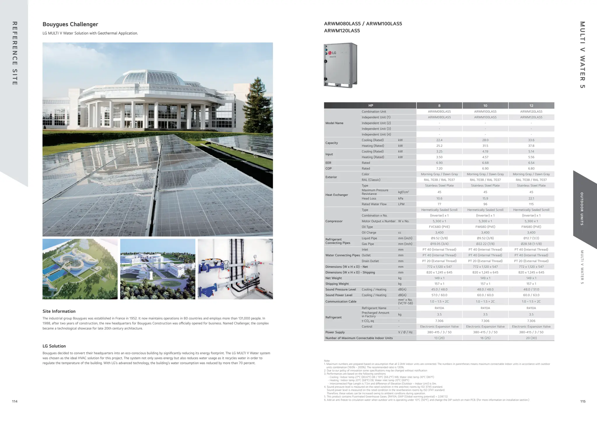

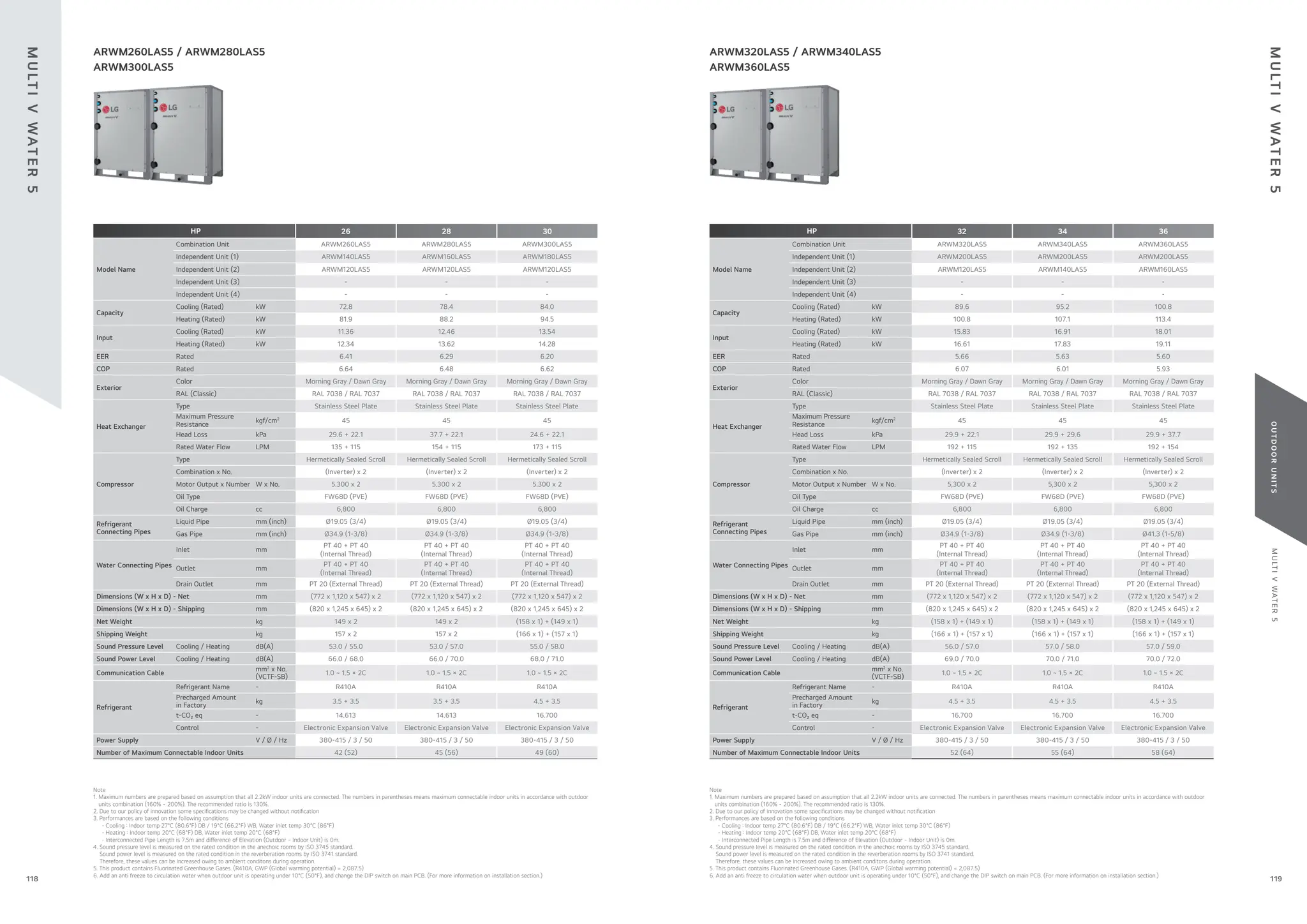
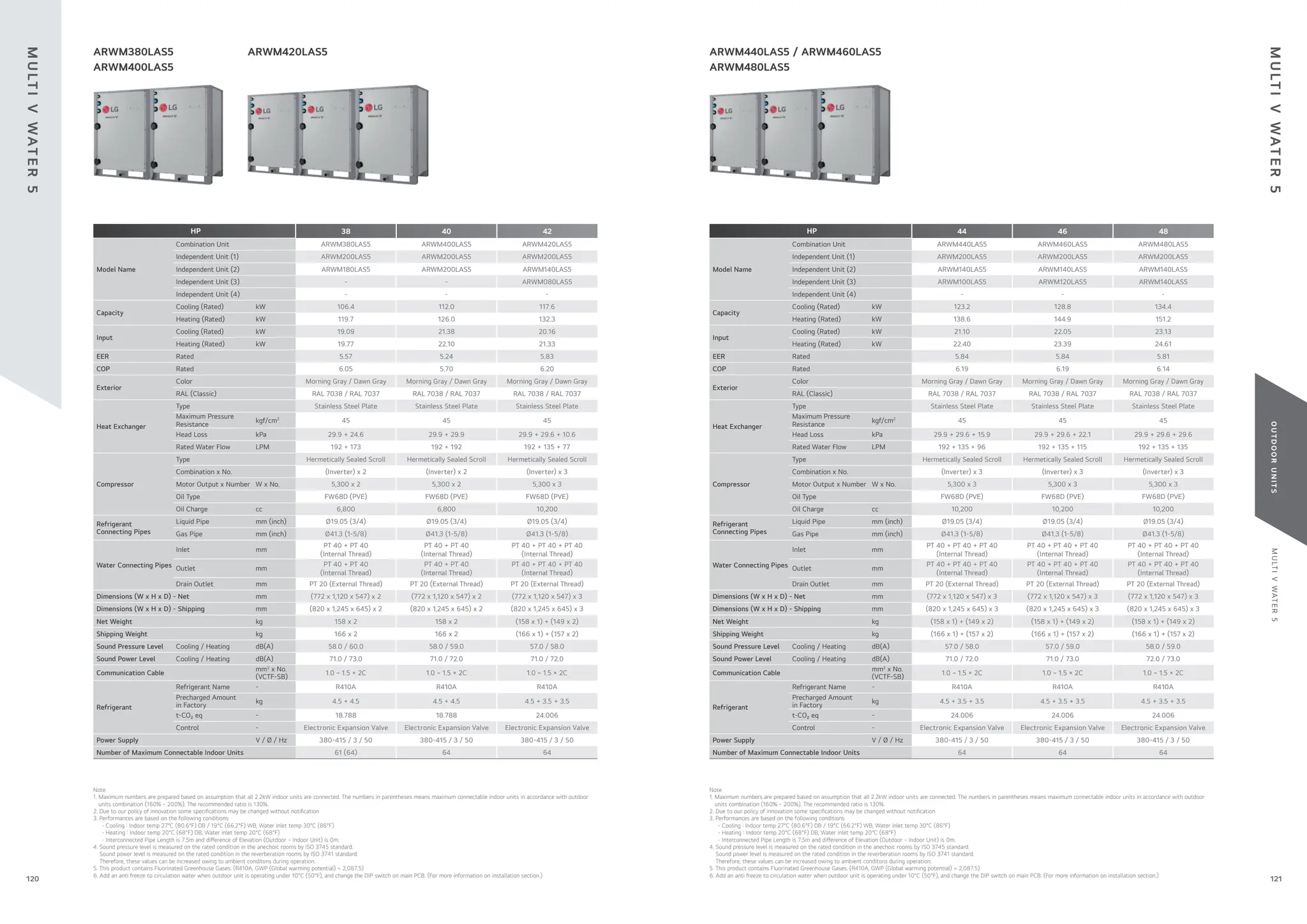
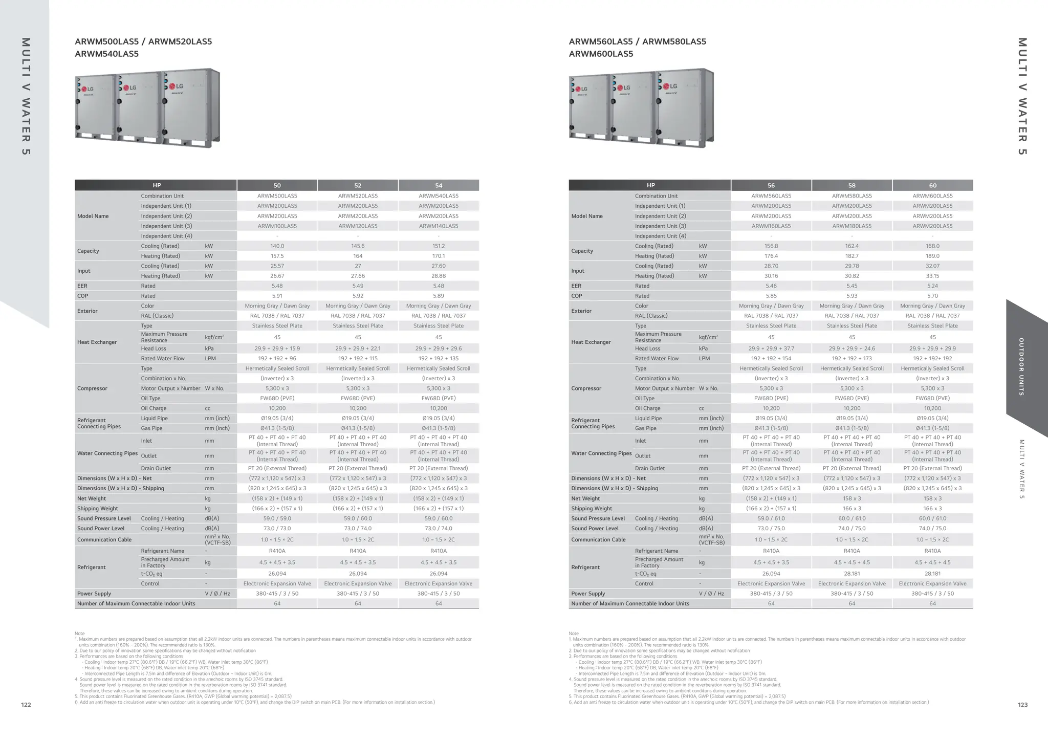
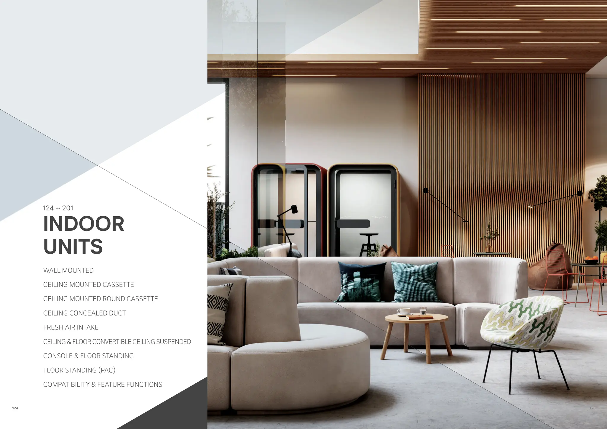


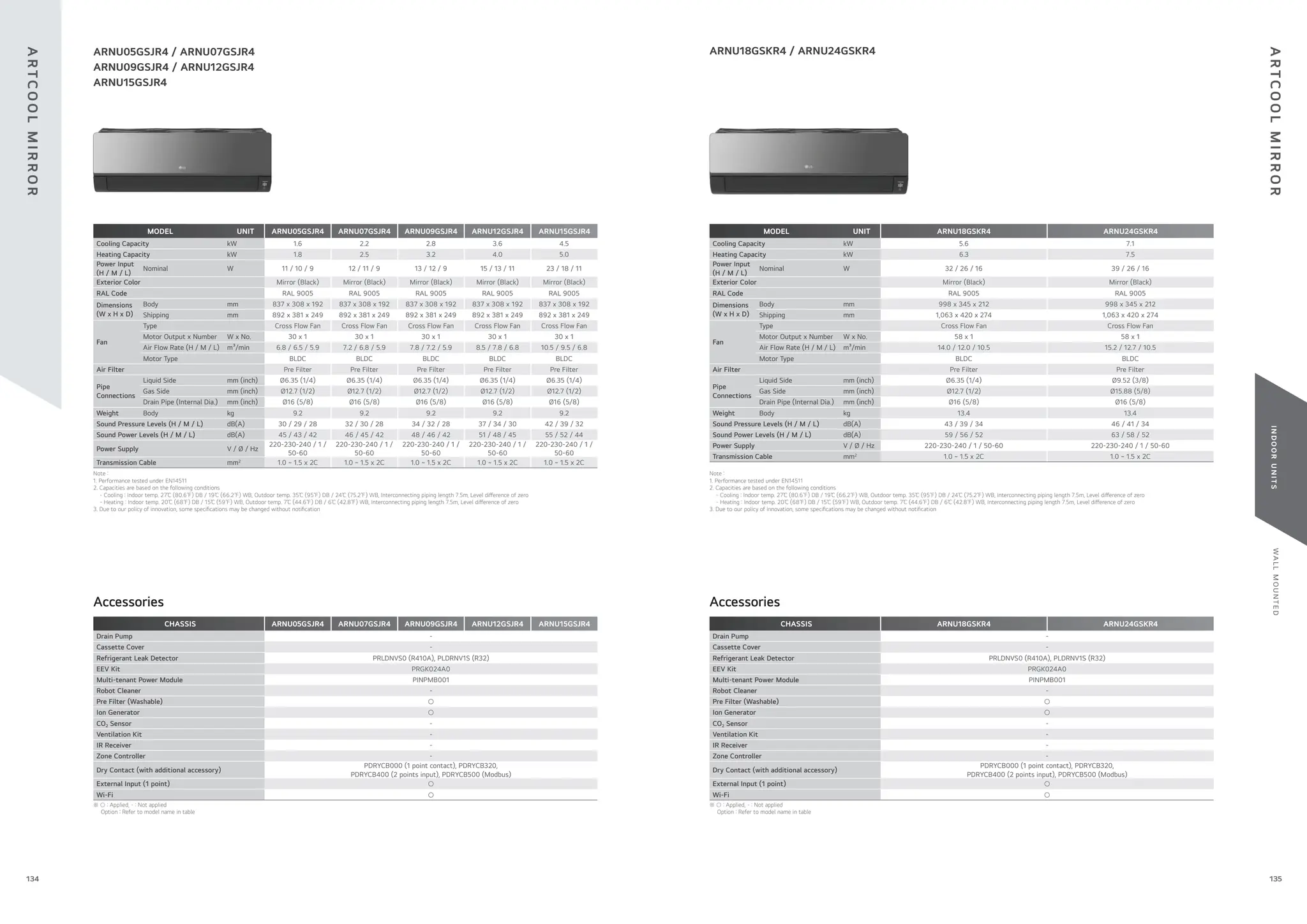


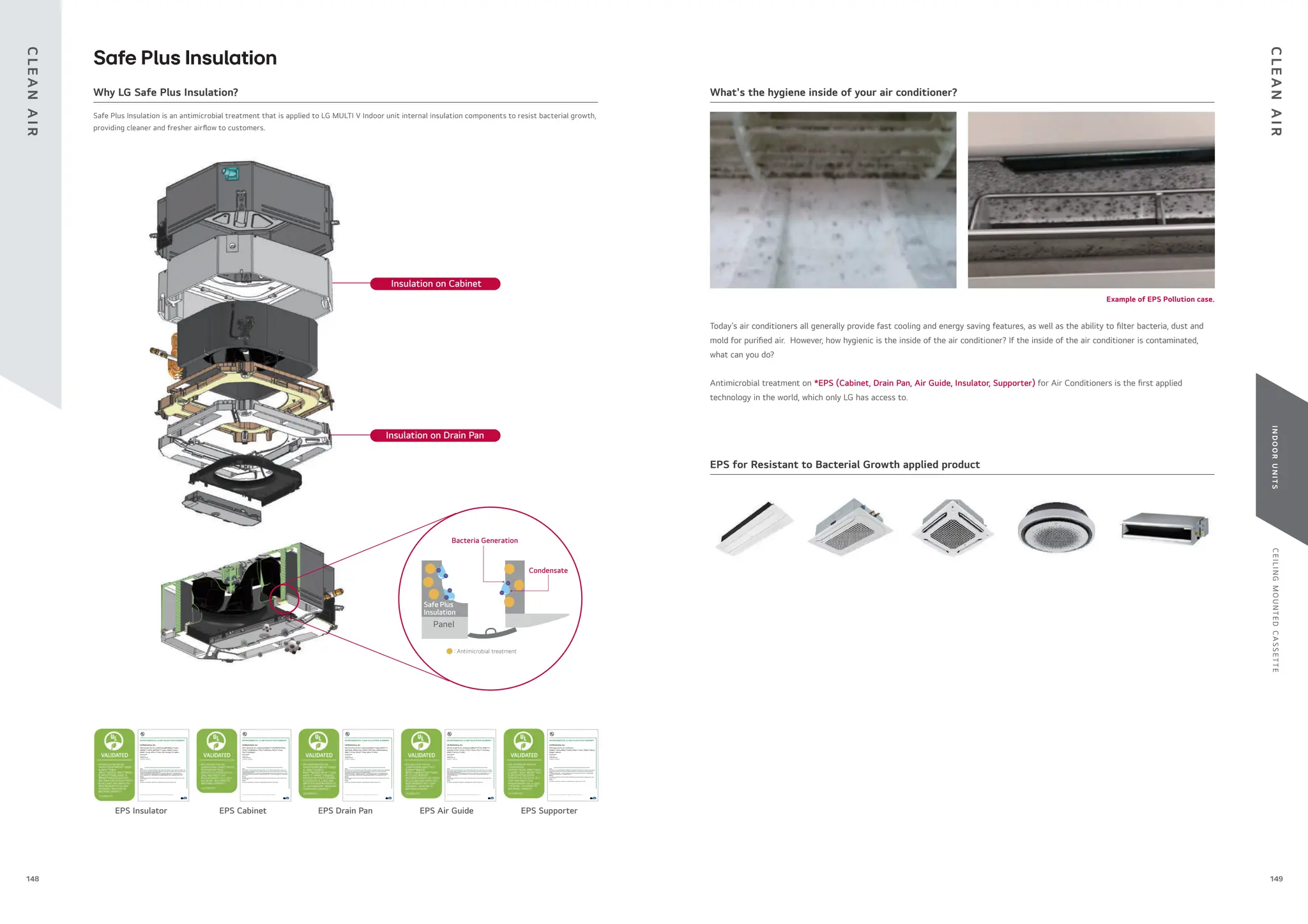
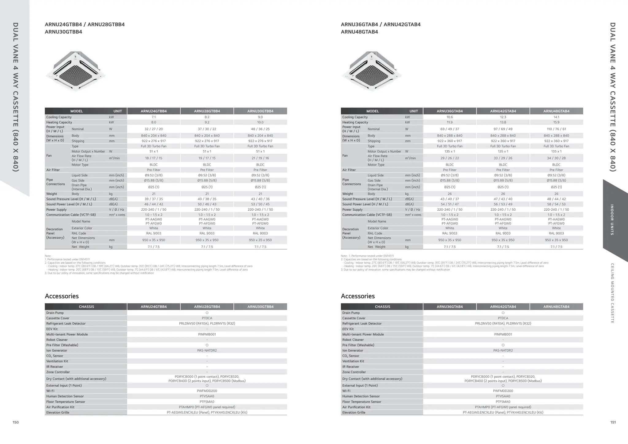


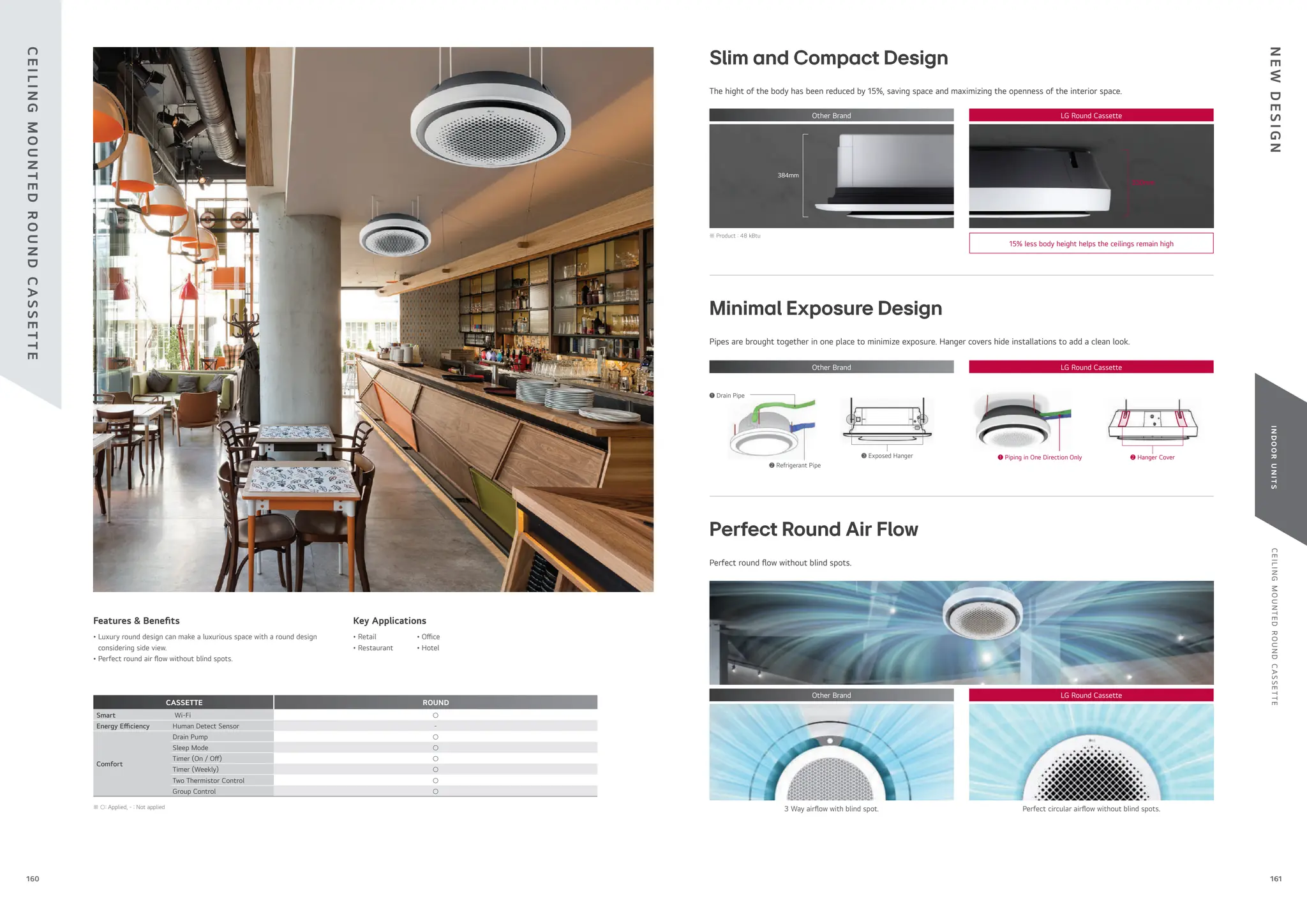


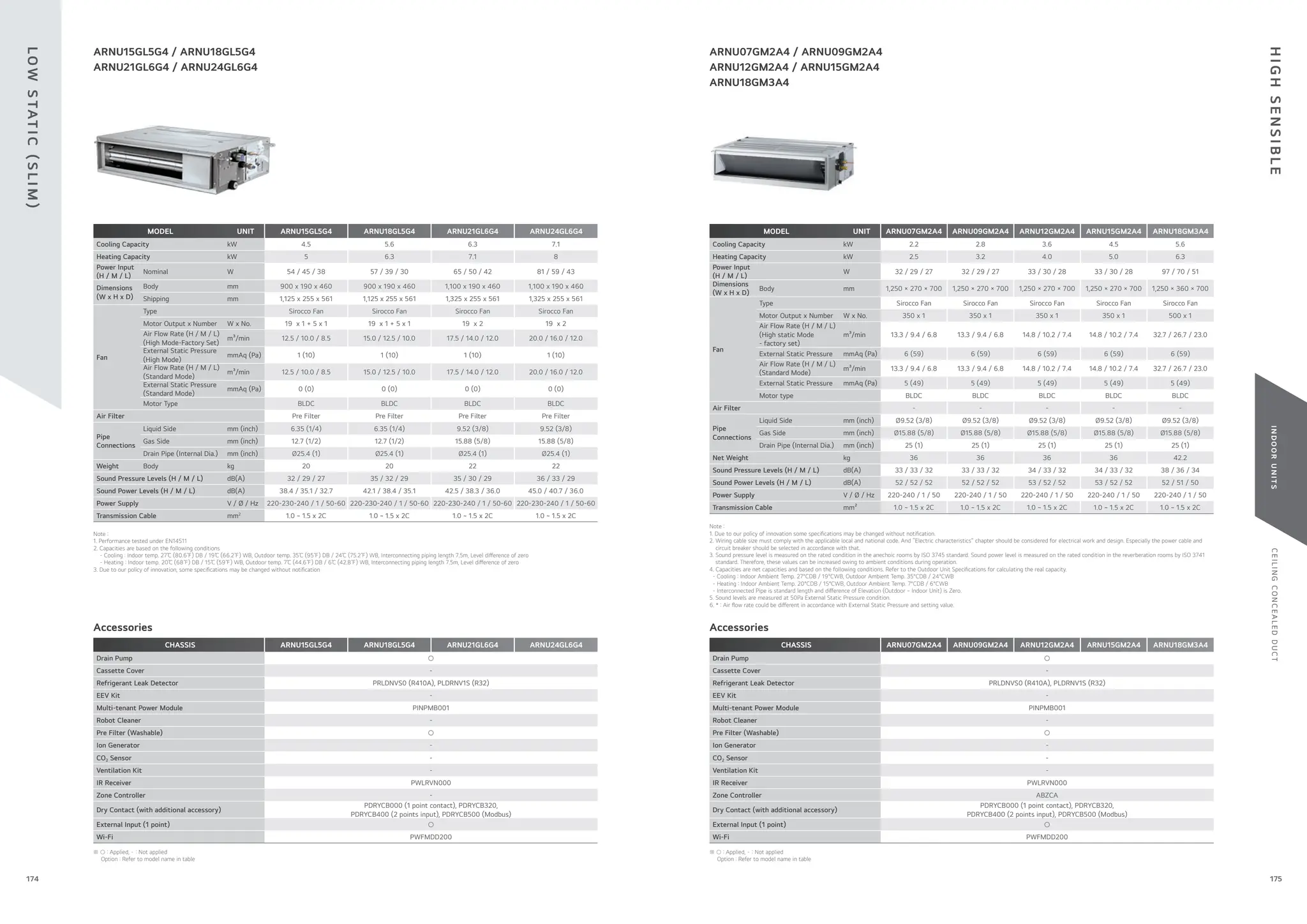


![C
O
M
PAT
I
B
I
L
I
T
Y
I
N
D
O
O
R
U
N
I
T
S
NO.
NEW
FUNCTION NAME
(4TH
GENERATION
INDOOR)
FUNCTION DESCRIPTION
REQUIRED CONTROLLER
REMARKS
WIRED REMOTE CONTROLLER CENTRALIZED CONTROLLER
WIRED
REMOTE
CONTROLLER
CENTRALIZED
CONTROLLER DELUXE
(PREMTA201)
PREMIUM
(PREMTA000
PREMTA000A
PREMTA000B)
STANDARD III
(PREMTB101)
(PREMTBB11)
STANDARD II
(PREMTBB01)
(PREMTB001)
SIMPLE
AC EZ
(PQCSZ250S0)
AC EZ TOUCH
(PACEZA000)
AC SMART 5
(PACS5A000)
ACP 5
(PACP5A000)
AC
MANAGER 5
(PACM5A000)
SIMPLE FOR
HOTEL
(PQRCHCA0Q
/ QW)
SIMPLE
(PQRCVCL0Q
/ QW)
1
Energy Monitoring
(Accumulated Electric
Energy Check)
Monitoring accumulated power
consumption
by Wired Remote Controller
○ ○
* Necessary to install the PDI (Power Distribution
Indicator) and central controller
* Combined with Multi V Water S outdoor unit, this
function is not available.
○ ○ ○ ○ - - - ○ ○ ○ ○
Monitoring accumulated power
consumption by Central Control Device
/ PDI
- ○
* Necessary to install the PDI (Power Distribution
Indicator)
* To make a report, central controller must be
installed
- - - - - - - ○ ○ ○ ○
2 2 Set Point
1) 2 set point control by Indoor and
central controller
2) Synchronization function with remote
control (Synchronization Setting and
Monitoring)
○ ○
* Wired remote controller and central controller must
be installed
* Combined with Multi V Water S outdoor unit, this
function is not available.
○ ○ ○ - - - - ○ ○ ○ ○
3
Occupied /
Unoccupied
Scheduling Function
(Sub Func. Enable)
1) Synchronization according to occupied
/ unoccupied by Indoor and Central
control
2) Synchronization icon with remote
controller (Synchronization Monitoring)
○ ○
* Centralized control is able to when you combine
only 4th generation indoor units (Use together with
2nd generation and 4th generation indoors, only
wired remote controller is able to set this function
as existing way)
* Wired remote controller or central controller must
be installed (Function can be activated using just
one control device.)
* Combined with Multi V Water S outdoor unit, this
function is not available.
○ ○ ○ - - - - ○ ○ ○ ○
4 Group Control Group Control can use Additional function ○ ○
* Check more details in PDB (Product Data Book)
* Central controller can create and control group.
○ ○ ○ ○ - - - - ○ ○ ○
5 Test Run (Heating)
Test run mode can be operated in cooling
mode and heating mode for easy service
○ - ○ ○ ○ ○ - - - - - - -
6
Model Information
Monitoring
Product Type / Indoor Type / Indoor
capacity information can be monitored by
remote controller
○ - ○ ○ ○ ○ - - - - - - -
7
Indoor unit address
checking
Wired remote controller can check indoor
unit address information
○ - ○ ○ ○ ○ - - - - - - -
8
Refrigerant Leakage
Detection
Function error sign display when
refrigerant leakage occurred
○ ○
* Central controller has been installed, CH230 error
code can be recognized (Old / New Same)
* Without Central Controller, it is able to recognize
with wired remote controller (CH230)
* Combined with Multi V Water S outdoor unit, this
function is not available.
* Accessory PRLDNVS0 must be separately ordered
○ ○ ○ ○ - - - - ○ ○ -
9
Thermo On / O
range
Setting (Cooling)
User can set cooling thermo on/o
range with wired remote controller for
prevention overcooling
○ - * Thermo On / O temperature setting (3 step) ○ ○ ○ ○ - - - - - - -
10
Thermo On / O
range
Setting (Heating)
User can set heating thermo on/o
range with wired remote controller for
prevention overheating. (4 Step)
○ - * Thermo On / O temperature setting (4 step) ○ (4 step) ○ (4 step) ○ (4 step) ○ (3 step) ○ (3 step) ○ (3 step) - - - - -
11
Static Pressure
11 Step Control
(Only for Ceiling
Concealed Duct Type)
Depends on the installation environment,
4th generation Ceiling Concealed Duct
can control the static pressure by 11 steps
for providing comfortable environment
○ - * Only applied in Ceiling Concealed Duct ○ ○ ○ ○ ○ ○ - - - - -
12
1 point External Input
(On / O control)
Indoor unit can be controlled by external
devices without purchasing
Dry contact as an accessory (All 4th
generation indoors)
○ -
* Simple On/O control by Dry Contact at Indoor
[Example of Contact port by product type]
* 2 Way Cassette : CN-CC Port (Wired remote
controller installation function mode 41 is required)
* 1 Way / 4 Way Cassette / Ceiling Concealed Duct /
Wall Mounted Unit / Console / FAU / Floor Standing
(with case / without case) : CN-EXT Port
○ ○ ○ ○ - - - - - - -
13
Filter Sign
(Remaining Time)
The alarm activates when the lter needs
to be cleaned, and the time remaining for
cleaning is displayed on the screen.
○ ○
* The alarm activates on the central controller, but
the remaining time is not displayed.
○ ○ ○ ○ - - ○ ○ ○ ○ ○
14
Auto restart function
Disable / Enable
After the power failure compensation,
stand by at OFF mode Restore the
operation for the status before the power
o
○ - ○ ○ ○ ○ - - - - - - -
15
Indoor Humidity
display
Monitoring indoor humidity Wired Remote
Controller
○ ○ * Available only with MULTI V i ○ ○ ○ - - - - - ○ ○ -
16
Comfort Cooling
setting
set the outdoor unit comfort cooling
operation value
○ ○ * Available only with MULTI V i ○ ○ ○ - - - - - ○ ○ -
17
Smart Load Control
setting
Change the outdoor unit’s Smart Load
Control stage value.
○ ○ * Available only with MULTI V i ○ ○ ○ - - - - - ○ ○ -
18
ODU Refrigerant
Noise Reduction
setting
set the outdoor unit’s refrigerant noise
reduction function
○ ○ * Available only with MULTI V i ○ ○ ○ - - - - - ○ ○ -
19
Low noise mode time
setting
set the start and end time of the outdoor
unit’s low noise mode operation
○ ○ * Available only with MULTI V i ○ ○ ○ - - - - ○ ○ ○ -
Note : 1) No.1, 2, 3, 8 : Functions are available to use together with 4th
generation Indoor units only. If used together 2nd
generation indoor unit and
4th
generation indoor unit functions will not be activate. Combined with MULTI V Water S outdoor unit this function is not available
2) No. 4, 5, 6, 7, 9, 10, 11, 12, 13, 14 : If used together 2nd
generation indoor unit and 4th
generation indoor unit these functions will be activate only in 4th generation indoor
3) 2nd
generation indoor unit : Ceiling & Floor Convertible Unit, Ceiling Suspended Unit, HYDRO KIT (Low Temp. / High Temp.), ERV DX (with Humidi er, without Humidi er), AHU Communication
Kit ※ ○ : Applied, - : Not applied
C
O
M
PAT
I
B
I
L
I
T
Y
C
O
M
PAT
I
B
I
L
I
T
Y
197
196](https://image.slidesharecdn.com/240222lgmultivcataloguelow-251206043823-67e9ad80/75/240222-LG-Multi-V-Catalogue_low-pdffdffdffdwfdfdsfdfewffgegg-99-2048.jpg)
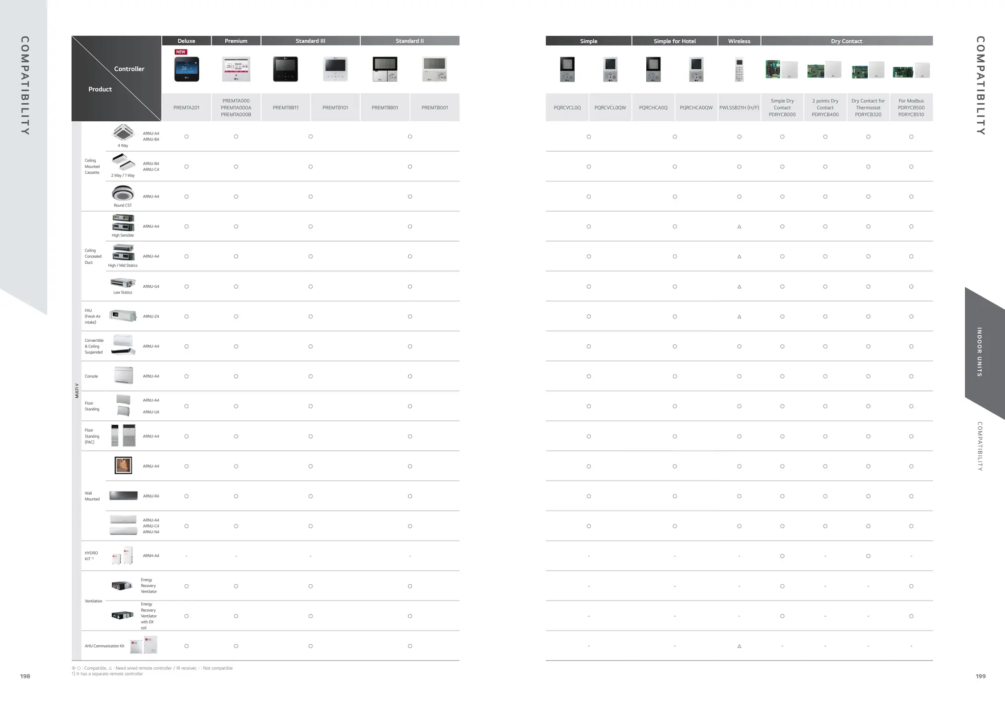


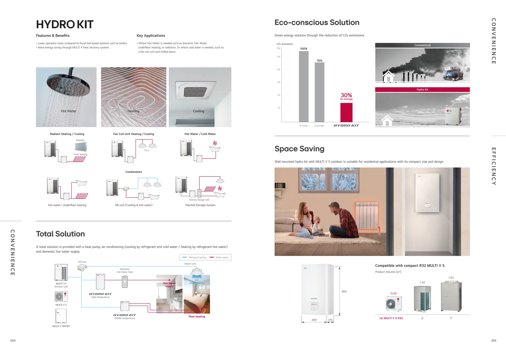


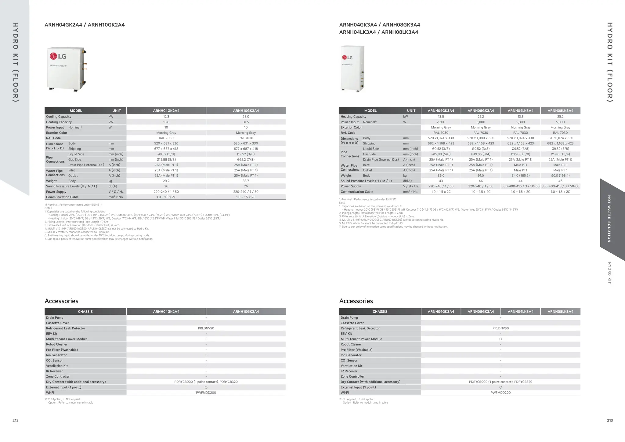
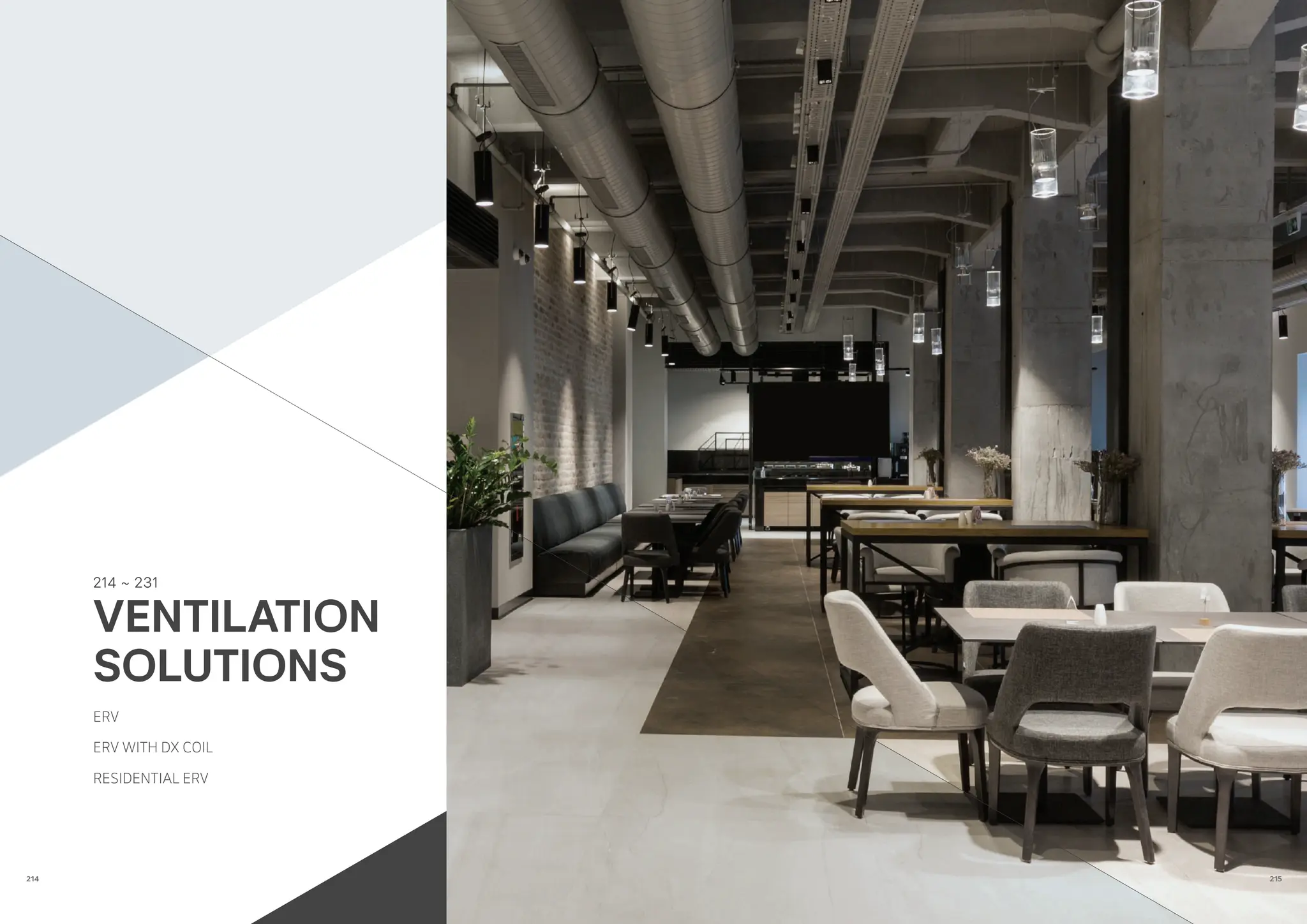

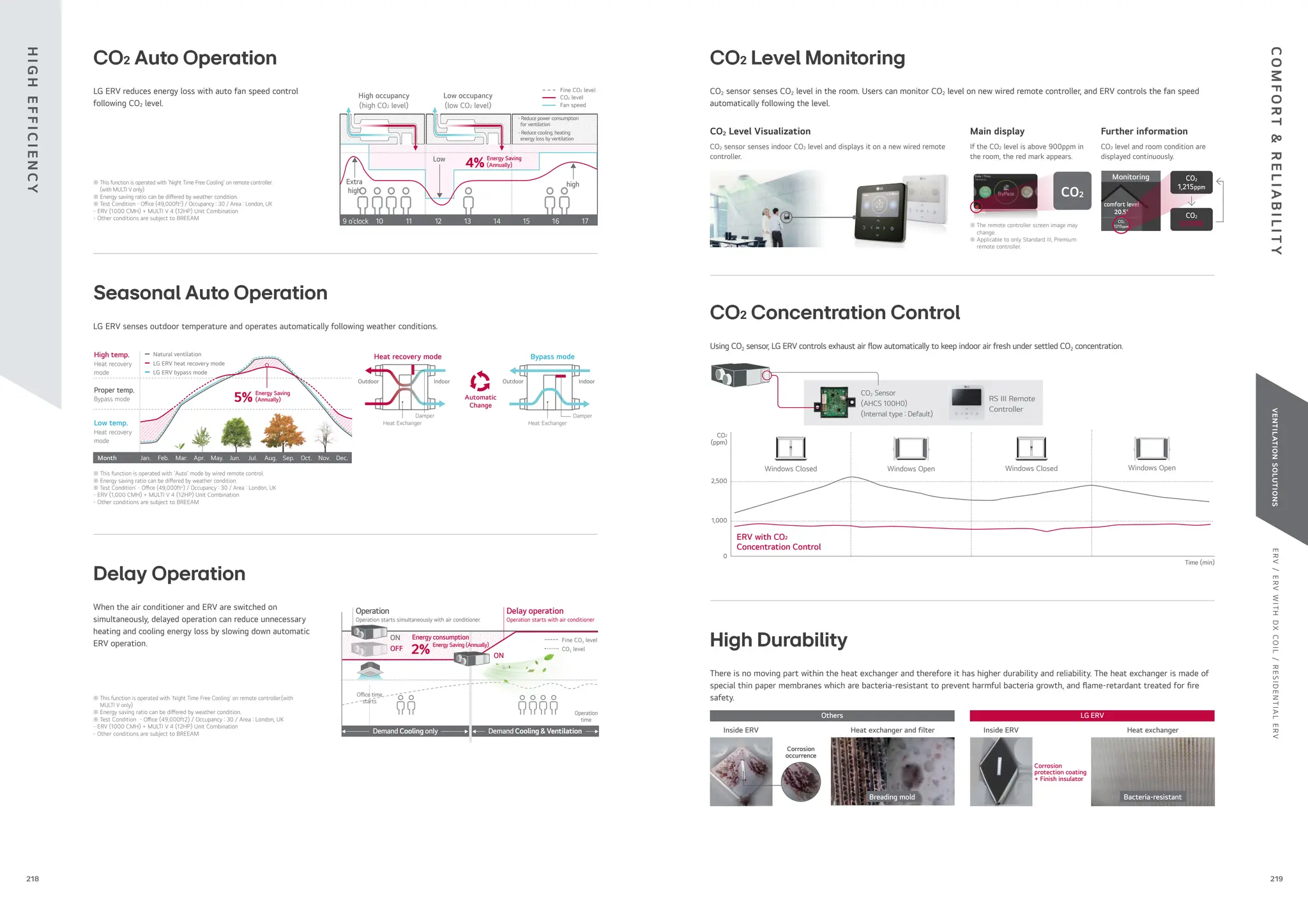
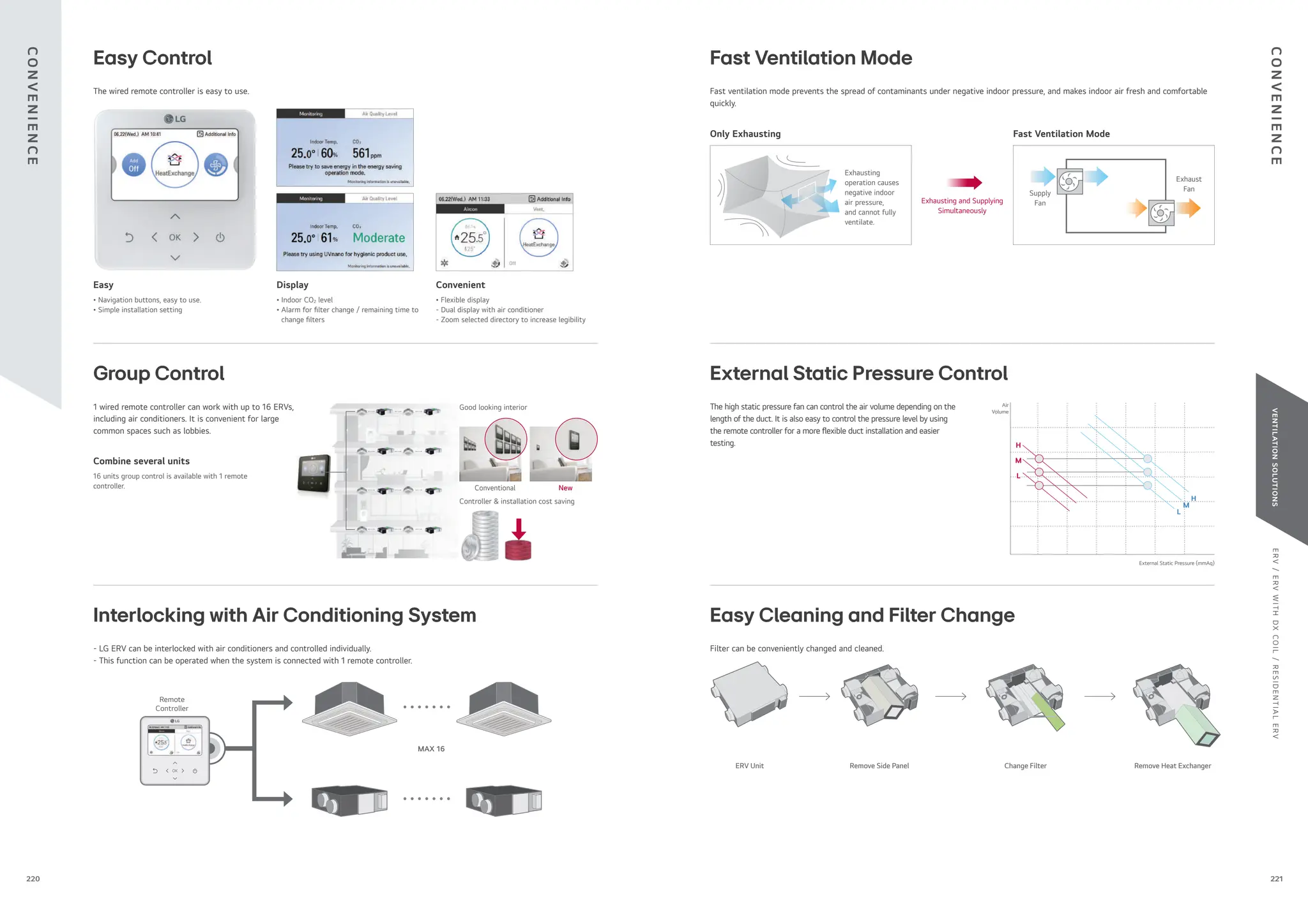


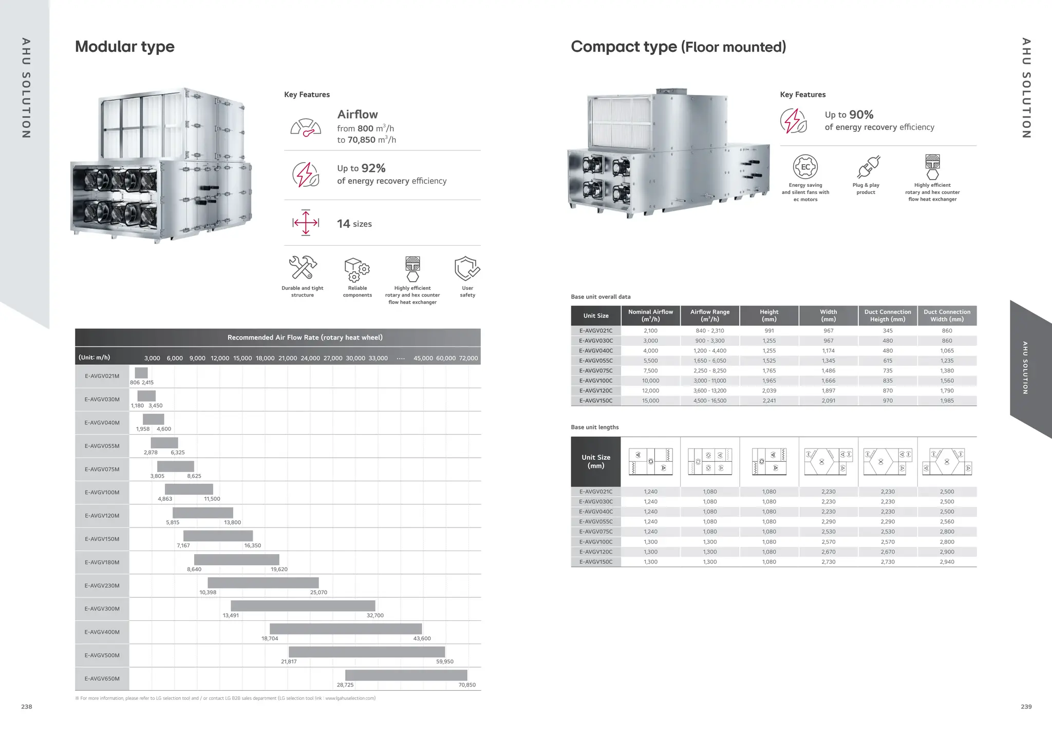


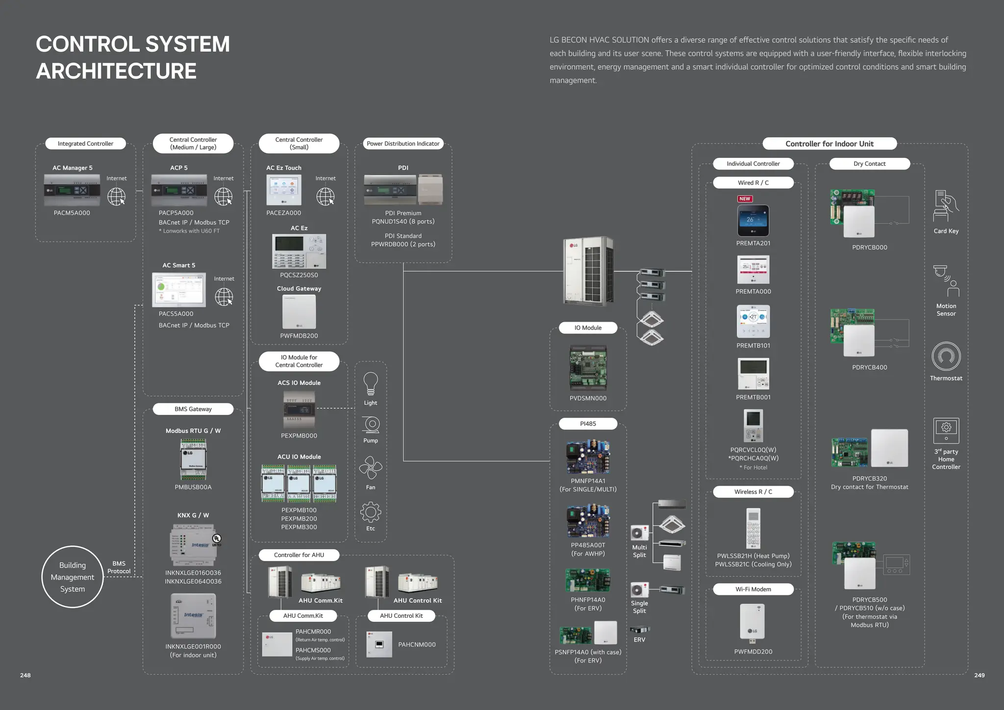


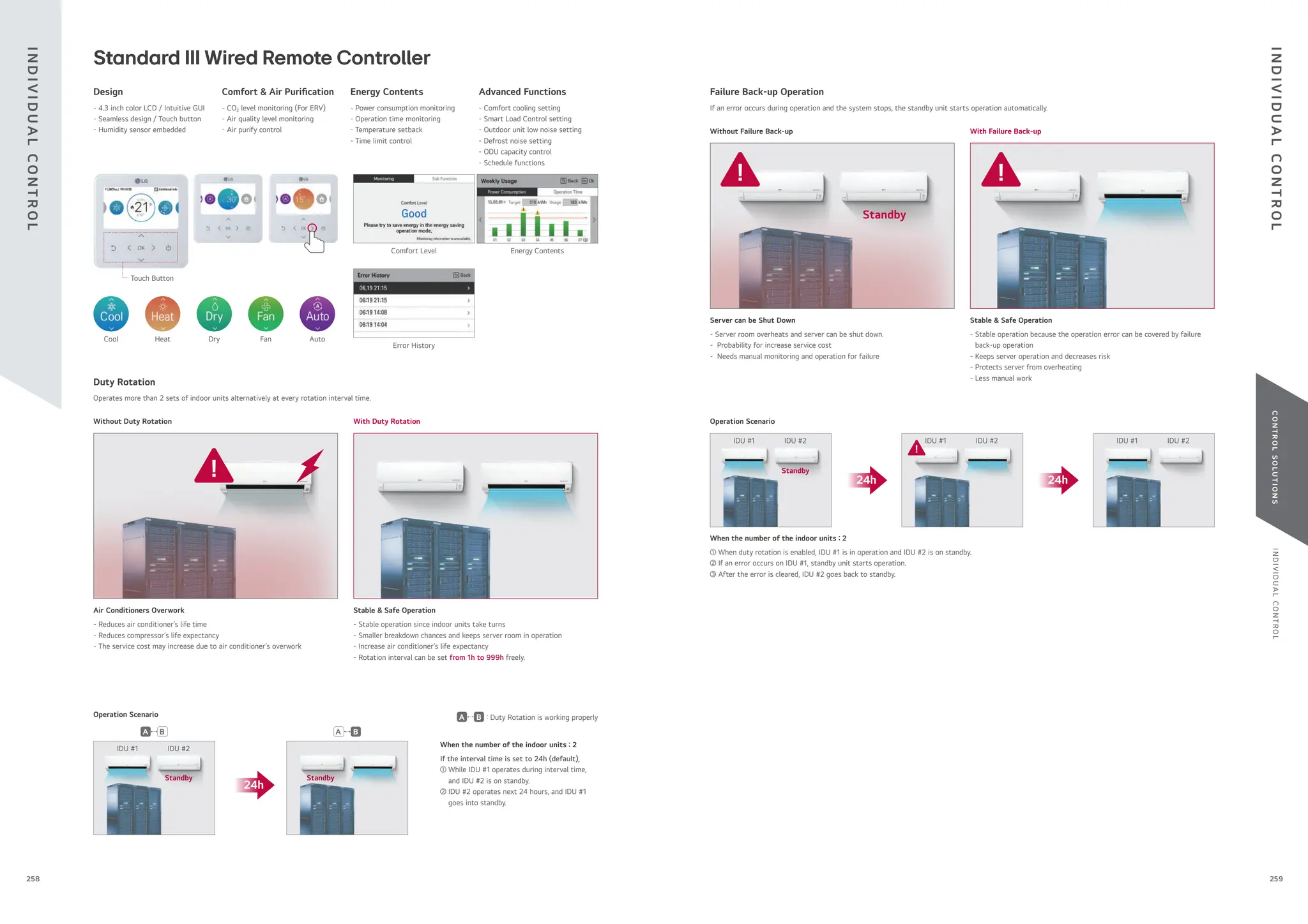

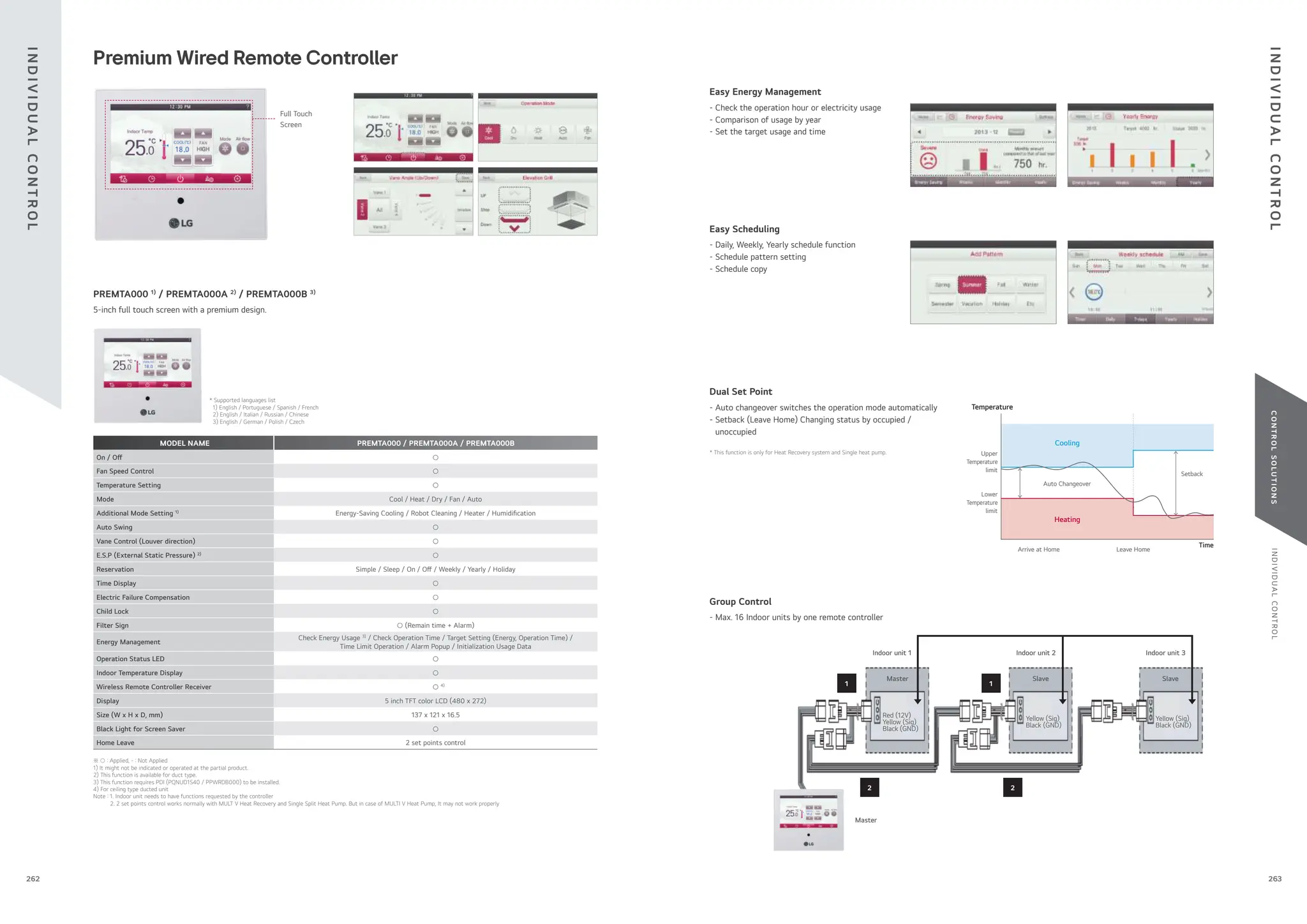

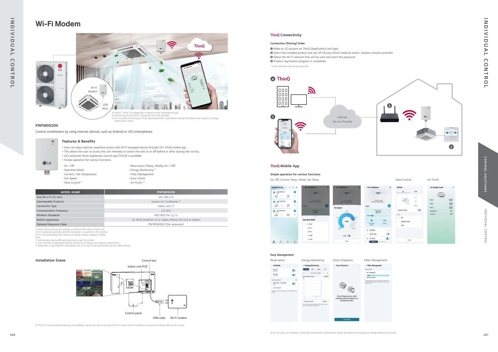
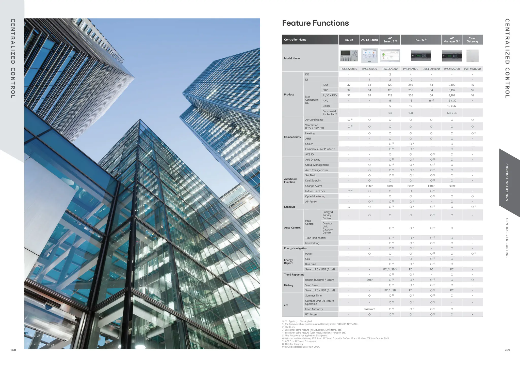


![C
E
N
T
R
A
L
I
Z
E
D
C
O
N
T
R
O
L
C
O
N
T
R
O
L
S
O
L
U
T
I
O
N
S
Air Quality Multi Status view
Air Purify Control
Air Quality Summary Widget
View Air Quality Trends
- Daily (per hour), period (30 days) shows trends
- Excel output / easy to manage
- Average Value
- View by Device
(Name, Air Quality value, Status)
Send out
- Easy setting of Air Purify function (Set / Clear)
Air Quality Level
Good
Average Air Quality
Good
Unhealthy
Moderate
Poor
Compressor Capacity Control IDU Operation Ratio Control IDU Operation Level
AC Manager 5
Smart Air Purify Solution
Total management of the air puri cation function creates a clean environment everyday.
Energy Navigation & Energy Usage Graph
Energy navigation is the function that sets the target usage amount to limit the monthly power consumption and control so that
the total accumulated power consumption does not exceed the target usage amount. It performs a total of 7 control levels with the
estimated / actual usage amount exceeding the ratio compared to the monthly target usage amount. For the control method, there are
indoor unit operation ratios, outdoor unit capacity control, and indoor unit operation controls.
Operation ratio (IDUs) Control ODU Capacity Control
Indoor unit Priority Control
gradually stop depending on importance
of room.
Robby < <
O ce VIP room
9 Step Operation Rate (%)
[ 0, 40, 45, 50, 60, 70, 80, 90, 100 ]
Compressor Hz Control
Peak Control
This function can reduce electricity use. There are two kinds of control logic: energy saving e ect by indoor unit operation control rate,
and load management e ect by outdoor unit capacity control.
Building West
Classroom
Faculty
Facilities
Floor #1
Floor #1
Floor #2
Floor #2
East
East
West
West
Multi Level Group Composition
Users can create frequency or multi-level groups, making it easier
to control and monitor the devices.
Advanced Network Accessibility & User Friendly GUI
As an advanced central controller, AC Manager 5 o ers a exible
interface for each user by assessing the device screen and
automatically customizing the layout to provide the most optimized
interface.
Air Purify
C
E
N
T
R
A
L
I
Z
E
D
C
O
N
T
R
O
L
C
E
N
T
R
A
L
I
Z
E
D
C
O
N
T
R
O
L
287
286](https://image.slidesharecdn.com/240222lgmultivcataloguelow-251206043823-67e9ad80/75/240222-LG-Multi-V-Catalogue_low-pdffdffdffdwfdfdsfdfewffgegg-144-2048.jpg)
![C
E
N
T
R
A
L
I
Z
E
D
C
O
N
T
R
O
L
C
O
N
T
R
O
L
S
O
L
U
T
I
O
N
S
Modbus Gateway Memory Map
Baud Rate : 9,600 bps, Stop Bit : 1 stop bit, Parity : None Parity, Byte size : 8 bits
NO.
DATA BIT
FUNCTION REGISTER
AIR CONDITIONER ERV / DX ERV HYDRO KIT & THERMA V
1 Operate (On / O ) Operate (On / O ) Operate (On / O ) 0 : Stop / 1 : Run
Register = N X 16 + ①
(N = Indoor Unit Central
Address)
2 Auto Swing Aircon Operate (On / O ) Hot Water Mode (On / O ) 0 : Disable / 1 : Enable
3 Filter Alarm Release Filter Alarm Release 1)
Reserved 0 : Normal / 1 : Alarm Release
4 Lock Remote Controller Lock Remote Controller Lock Remote Controller 0 : UnLock / 1 : Lock
5 Lock Operate Mode Lock Operate Mode 1)
Reserved 0 : UnLock / 1 : Lock
6 Lock Fan Speed Lock Fan Speed 1)
Reserved 0 : UnLock / 1 : Lock
7 Lock Target Temp. Lock Target Temp. 1)
Reserved 0 : UnLock / 1 : Lock
8 Lock IDU Address Lock IDU Address 1)
Reserved 0 : UnLock / 1 : Lock
9 Reserved Quick Ventilate Reserved 0 : Disable / 1 : Enable
10 Reserved Energy Save Reserved 0 : Disable / 1 : Enable
Coil Register (0 x 01)
1) : This register value is applied ‘DX Ventilator’ ONLY.
Discrete Register (0 x 02)
NO.
DATA BIT
FUNCTION REGISTER
AIR CONDITIONER ERV / DX ERV HYDRO KIT & THERMA V
1 Connected IDU Connected IDU Connected IDU
0 : Disconnected /
1 : Connected
Register = N X 16 + ①
(N = Indoor Unit Central
Address)
2 Alarm Alarm Alarm 0 : Normal / 1 : Alarm
3 Filter Alarm Filter Alarm 1)
Hot Water Only 2)
• 0 : Normal /
1 : Alarm Hydro Kit
• 0 : Normal /
1 : Hot Water Only
4 Reserved Reserved Target Temp. Select 0 : Air / 1 : Water
5 Reserved Reserved Error Division 2) 0 : CH type error /
1 : BC type error
1) : This register value is applied ‘DX Ventilator’ ONLY.
2) : This register value is applied ‘Hydro Kit’ ONLY.
Input Register (0 x 04)
NO.
DATA BIT
FUNCTION REGISTER
AIR CONDITIONER ERV / DX ERV HYDRO KIT & THERMA V
1 Error Code Error Code Error Code
0 ~ 255
※ Please refer to the product
error table.
Register = N X 20 + ①
(N = Indoor Unit Central
Address)
2 Room Temp. RA Temp. Room Temp. -99.0 ~ 99.0 [°C] x 10
3 Pipe In Temp. OA Temp. 1)
Water Inlet Temp. -99.0 ~ 99.0 [°C] x 10
4 Pipe Out Temp. SA Temp. 1)
Water Outlet Temp. -99.0 ~ 99.0 [°C] x 10
5 Reserved Pipe In Temp. 1)
Sanitary Tank Temp. -99.0 ~ 99.0 [°C] x 10
6 Reserved Pipe Out Temp. 1)
Solar Temp. 2)
-99.0 ~ 99.0 [°C] x 10
1) : This register value is applied ‘DX Ventilator’ ONLY.
2) : This register value is applied ‘AWHP’ ONLY.
Holding Register (0 x 03)
NO.
DATA BIT
FUNCTION REGISTER
AIR CONDITIONER ERV / DX ERV HYDRO KIT & THERMA V
1 Operate Mode Operate Mode Operate Mode
• 0 : Cooling, 1 : Dehumidifying,
2 : Fan, 3 : Auto, 4 : Heating
Hydro Kit (Middle Temp. DHW)
/ AWHP
• 0 : Cooling, 3 : Auto, 4 :
Heating Hydro Kit (High Temp.
DHW)
Register = N X 20 + ①
(N = Indoor Unit Central
Address)
2 Fan Speed Fan Speed Target Temp. DHW 2) 1 : Low, 2 : Mid, 3 : High,
4 : Auto
3 Target Temp. Target Temp. 1)
Target Temp. 2)
16.0 ~ 30.0 [°C] x 10
4 Target Temp. Limit (Upper) Target Temp. Limit 1)
(Upper) Reserved 16.0 ~ 30.0 [°C] x 10
5 Target Temp. Limit (Lower) Target Temp. Limit 1)
(Lower) Reserved 16.0 ~ 30.0 [°C] x 10
6 Reserved Vent. Operate Mode Reserved 0 : HEX, 1 : Auto, 2 : Normal
1) : This register value is applied ‘DX Ventilator’ ONLY.
2) : This value range can be between 0 ~ 127 [°C]. And it would be limited by upper & lower value according to the setting of remote controller.
1) LGAP is LG Protocol.
Max. 16 ODU units in RS-485
Providing MODBUS RTU connection between LG Air conditioners and BMS.
Features & Bene ts
• Function
- Modbus RTU communication with Modbus master controller
- Modbus RTU slave (RS485) / 9,600 bps
- Applicable for MULTI V i, MULTI V 5, ERV, Heating
- Size (W x H x D, mm) : 53.6 x 89.7 x 60.7
- Max. 16 IDUs with single module / Max. 64 IDUs with 4 modules
- Power : DC 12V (250mA)
- No slave allowed in LGAP
Installation Scene
BMS
RS485 (LGAP 1)
)
Modbus
Single Module
Max. 16 indoor units with a single module
BMS
Modbus RS485 (LGAP 1)
)
Max. 16 ODU units in
RS-485 (LGAP) line
Multiple Module
Max. 64 indoor units with 4 modules in one Modbus communication line
PMBUSB00A
MODBUS RTU Gateway
C
E
N
T
R
A
L
I
Z
E
D
C
O
N
T
R
O
L
C
E
N
T
R
A
L
I
Z
E
D
C
O
N
T
R
O
L
289
288](https://image.slidesharecdn.com/240222lgmultivcataloguelow-251206043823-67e9ad80/75/240222-LG-Multi-V-Catalogue_low-pdffdffdffdwfdfdsfdfewffgegg-145-2048.jpg)
![C
E
N
T
R
A
L
I
Z
E
D
C
O
N
T
R
O
L
C
O
N
T
R
O
L
S
O
L
U
T
I
O
N
S
LG-KNX gateway allows fully bi-directional communication between LG VRF systems and KNX installations.
One gateway, one AC unit : This is the solution of ONE-TO-ONE integration. All required KNX DPT objects are fully compatible
with all KNX thermostats in the market. The gateway is wired directly to an indoor unit. This allows not only the control of the
main AC functions such as operating mode, fan speed, temperature setpoint, but also the monitoring of errors and alarms.
Key features
• KNX certi ed.
• Con gured by ETS standard con guration tool.
• KNX database available on ETS5 / 6
• Reduced dimensions allowing a quick installation inside the Air Conditioner unit.
• All the required DPT objects are 100% compatible with all KNX termostats in the market.
• Energy e ciency functions, such as “timeout”
, “open window” or “occupancy”
.
• Smooth integration of KNX thermostats allowing the control of the AC unit by the thermostat’s own
temperature sensor (Virtual Temperature)
• Simultaneous control of the AC unit by LG remote controller and KNX.
Key bene ts
• Optimization cost for small or medium installations.
• Decentralized device control : one gateway connected to each indoor unit.
• Easy integration on KNX installations
• Intuitive con guration
Key messages
• Total control and monitoring of the AC unit from KNX, including AC unit’s internal variables, running
hours counter (for lter maintenance control) and error indication (CH Error Codes).
• Fully integrated solution on Engineering Tool Software ETS5 / 6 by database product
INKNXLGE001R000 (For Indoor Unit)
KNX LG solution concept
Installation Scene & LG Topology
Windows
blinds
Key
Movement
sensor Switch
Window
contact
Lighting Alarms HVAC
Touch
screen
Enegy
management
[Optional]
Binary Inputs
Web landing page
of the product
Database available directly on ETS5/6
under INTESIS manufacturer
KNX Product Con guration by ETS Data Base
KNX Gateway
- Only needed during con guration.
- One single tool for the con guration of the whole range of Intesis KNX gateway series.
- Supplied with Intesis gateway with no additional cost.
- Con guration examples for all systems that can be integrated.
- Mapping table editable using excel, allowing a simple and fast association of KNX Group
Addresses, exported from ETS, to Intesis gateway’s datapoints.
- Includes powerful and useful features for con guration, setup and troubleshooting.
Intesis MAPS
Con guration software
Specially designed to allow monitoring and bidirectional control of all the parameters and functionality of LG air conditioners
from KNX protocol.
Key features
• 2 model types
• Up to 64 connectable indoor units
• Direct connection to KNX TP1 bus
• Independent management of communications
• Power supply : 9 to 36V DC or 24V AC (not included)
• KNX Power consumption : 5mA
• Standard DIN-Rail 6 modules enclosure
• LG Slave Central controller (for example, AC Smart) and PDI can be operated with KNX gateway
Key bene ts
• Easy & quick installation : user comfort
• Flexible integration (Intesis MAPS & KNX) Export Group Address by “csv” le to ETS5/6
• Compatibility with all LG products (Air-Conditioning, ERV, Hydrokits and AWHP)
• Ergonomic & friendly user interface (using the supplied software Intesis MAPS)
• One single tool for settings, commissioning, SW update and troubleshooting
Key messages
• Manage your building with an advanced building automation solution
• Energy savings
• Power consumption measurement using additional LG PDI device
• Bidirectional communication between LG & KNX
• Your system diagnostics accessible through LG Error codes
INKNXLGE016O036 (Indoor Unit ~16) / INKNXLGE064O036 (Indoor Unit ~64)
Easy to use tool for the con guration of Intesis gateway, in a fast and e ective way.
It o ers the maximum integration possibilities with a minimal knowledge required on the system to be integrated.
Intesis MAPS is Con guration Software for Intesis KNX Gateway Series
Installation Scene
MODEL NAME MAX. CONNECTION INDOOR UNITS
INKNXLGE016O036 16
INKNXLGE064O036 64
Technical and service support must come from Intesis directly.
LG Electronics Inc. warrants and assumes no liability for this product.
- This is the landing page of INTESIS MAPS: https://www.intesis.com/products/intesis-maps-home.
Up to 64
indoor units
USB
con guration
Windows
blinds Lighting Alarms HVAC
Touch
screen
Enegy
management
Outdoor
units
PI485
Ethernet TCP
Integration of LG VRF systems into KNX control systems
Direct download
of INTESIS MAPS
con guration software
C
E
N
T
R
A
L
I
Z
E
D
C
O
N
T
R
O
L
C
E
N
T
R
A
L
I
Z
E
D
C
O
N
T
R
O
L
291
290](https://image.slidesharecdn.com/240222lgmultivcataloguelow-251206043823-67e9ad80/75/240222-LG-Multi-V-Catalogue_low-pdffdffdffdwfdfdsfdfewffgegg-146-2048.jpg)
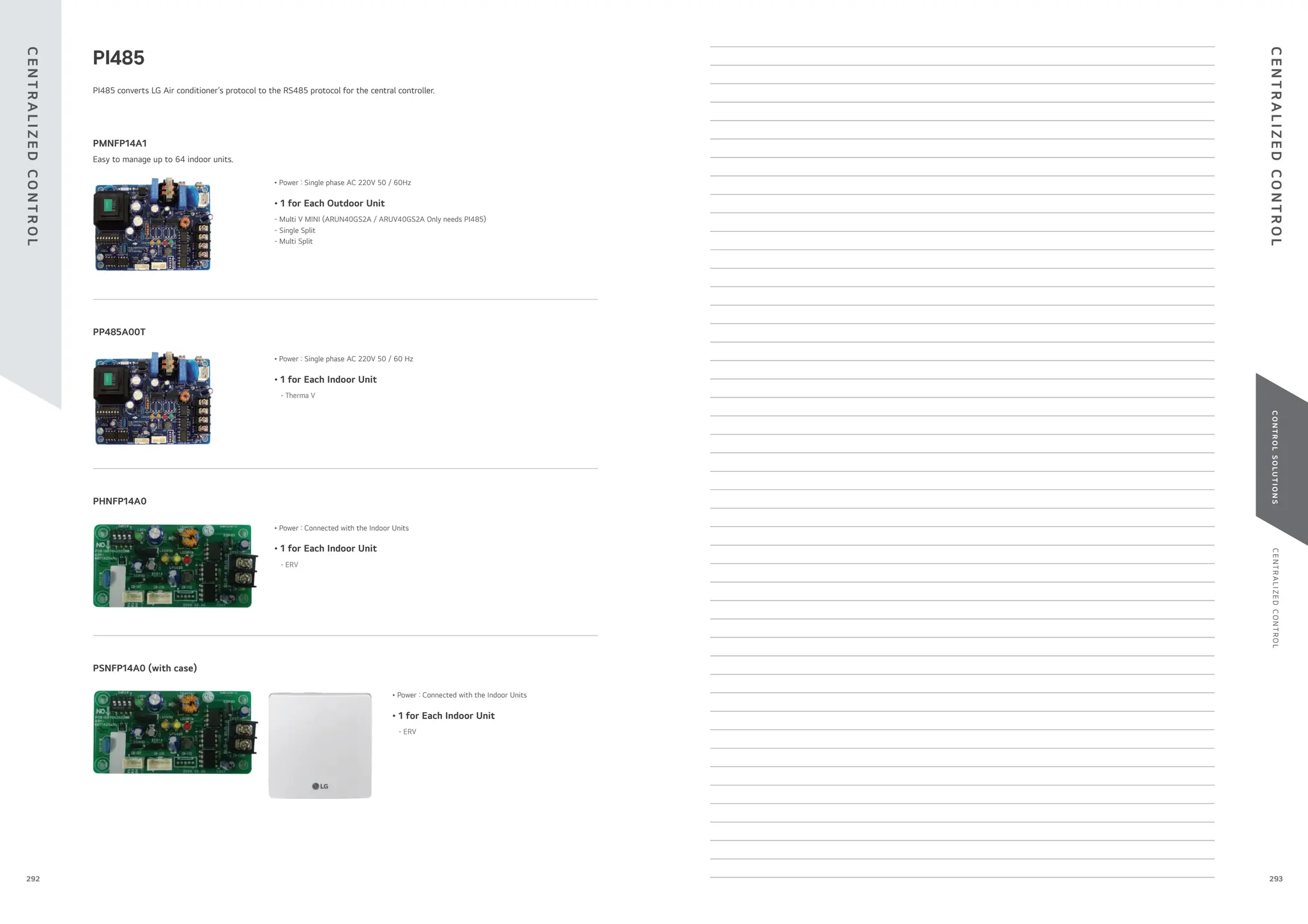

![I
N
T
E
G
R
AT
I
O
N
D
E
V
I
C
E
C
O
N
T
R
O
L
S
O
L
U
T
I
O
N
S
Note :
1. Power cable and type could be di erent from this scene depending on the Outdoor unit’s speci cation.
2. Measured power consumption could be di erent between PDI and Watt meter.
3. Applicable Central Controller : ACP 5, ACP LonWorks, AC Smart 5, AC Ez Touch
(Combination : we recommend to connect separated watt meter for Outdoor units to have correct power distribution value)
SELECT
MENU
[00] [01] [02][03]
[10] [11] [12] [13]
[20] [21] [22] [23]
[30] [31] [32] [33]
[ Slave 1]
Measurement
AC Manager 5
ACP 5
AC Smart 5
50kW
70kW
160kW
50kW
Graphing
[ Master ]
ACP
(00) ~ (03)
MENU
SELECT
SELECT
MENU
Pulse Line
RS485
220 V ~
BUS-A BUS-B
24 V ~
ACP 5
AC Smart 5
ACS Central Controller
PDI Power Source
WHM
(Watt-Hour Meter)
PDI
Power
Pulse Signal
100kWh
ACP 5
AC Smart 5
30kWh
A Shop
30kWh
C Shop
20kWh
B Shop
20kWh
D Shop
PDI shows the distributed power consumption of up to 128 indoor units.
Energy
monitoring
Max. 128
IDUs
ELECTRICITY / GAS
DISTRIBUTION
ENABLES EHP / GAS
CONSUMPTION
EHP
GAS
PQNUD1S40 (Premium, 8 ports) / PPWRDB000 (Standard, 2 ports)
MODEL NAME PQNUD1S40 PPWRDB000
Size (W x H x D, mm) 270 x 155 x 65
Interfaceable Products Air conditioner, ERV DX, Hydro kit, Thermal V
Maximum Number of Power Meters
EHP : 8 Watt meter
GHP : 4 Watt meter / 4 Gas meter
EHP : 2 Watt meter
GHP : 1 Watt meter / 1 Gas meter
Maximum Number of
Indoor Units
EHP : 128
GHP : 64
Data Backup When Power Outage ○
Power Input PDI : AC 24V, Transformer : AC 220V
※ ○ : Applied, - : Not Applied
Features & Bene ts
• Enables total and indoor power consumption monitoring.
• With LG central control connectivity, energy monitoring, energy savings operations and target usage setting functions are enabled.
• Enables gas consumption and electricity distribution.
PDI (Power Distribution Indicator)
I
N
T
E
G
R
AT
I
O
N
D
E
V
I
C
E
I
N
T
E
G
R
AT
I
O
N
D
E
V
I
C
E
297
296](https://image.slidesharecdn.com/240222lgmultivcataloguelow-251206043823-67e9ad80/75/240222-LG-Multi-V-Catalogue_low-pdffdffdffdwfdfdsfdfewffgegg-149-2048.jpg)

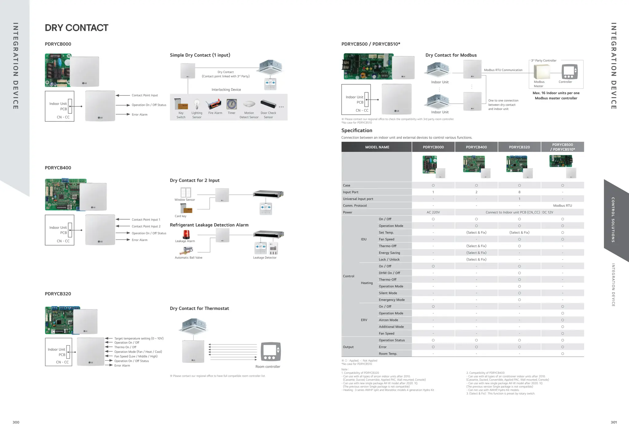

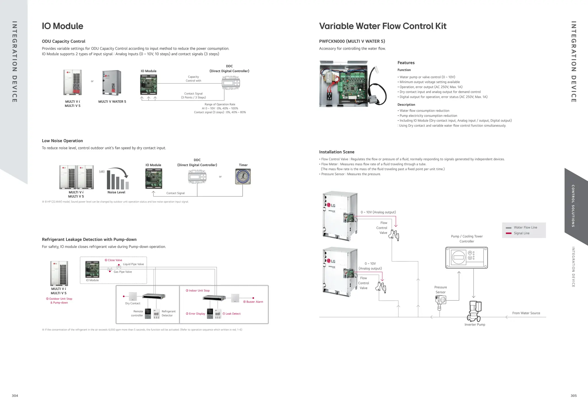


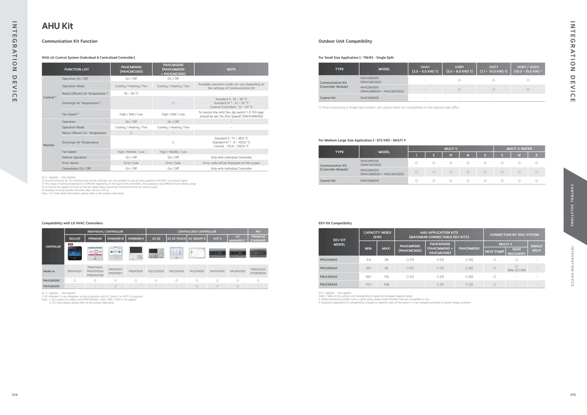

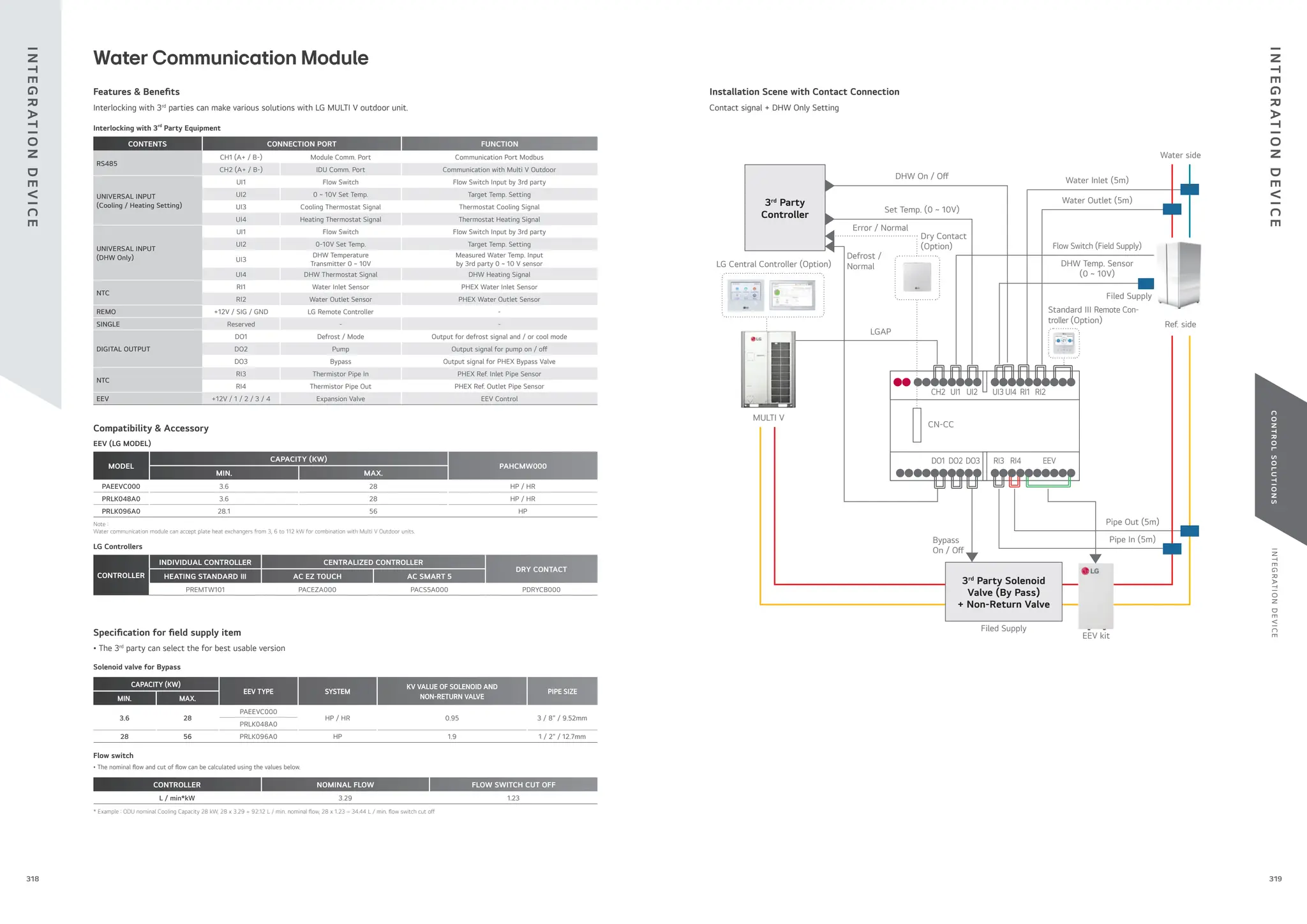
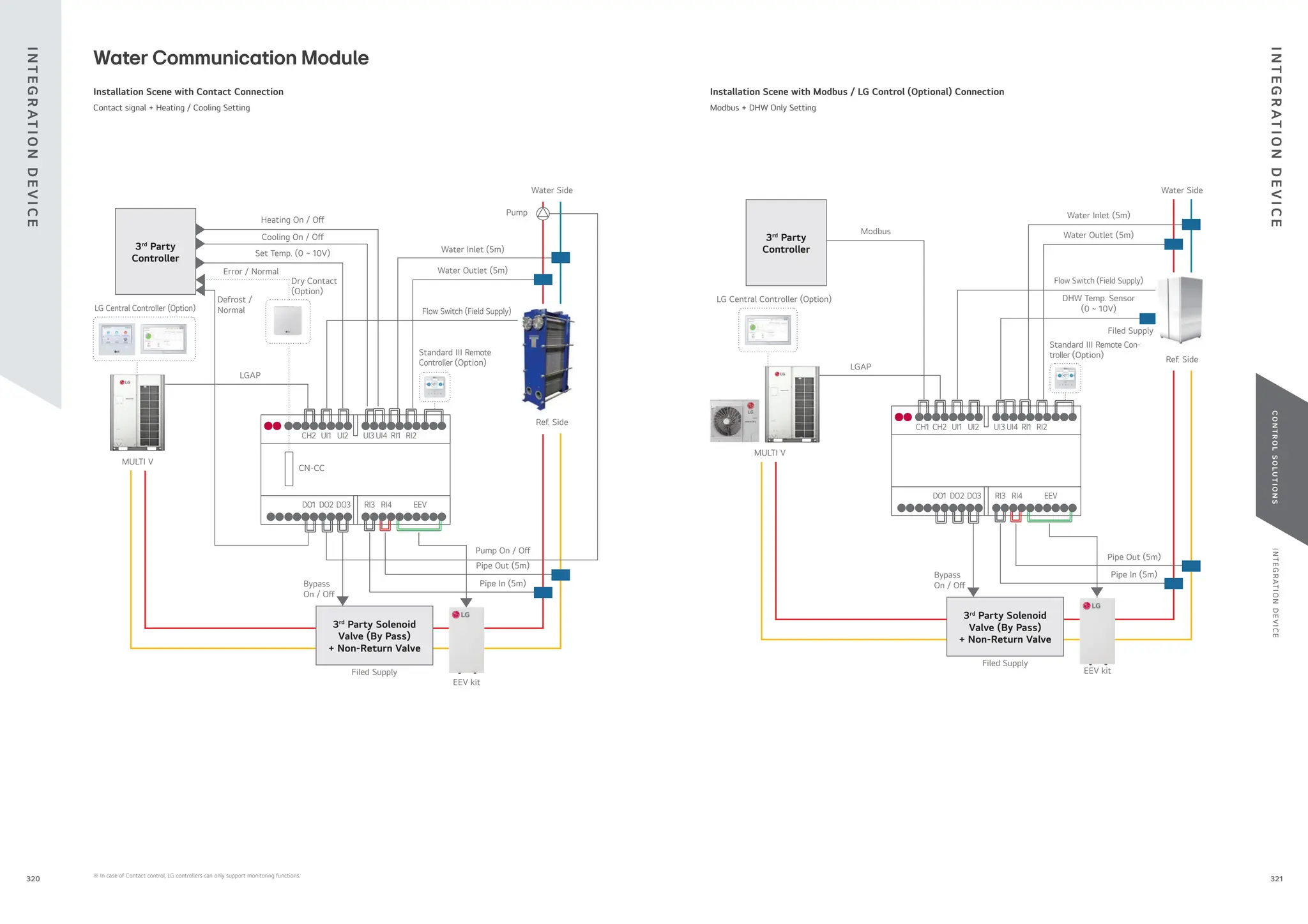
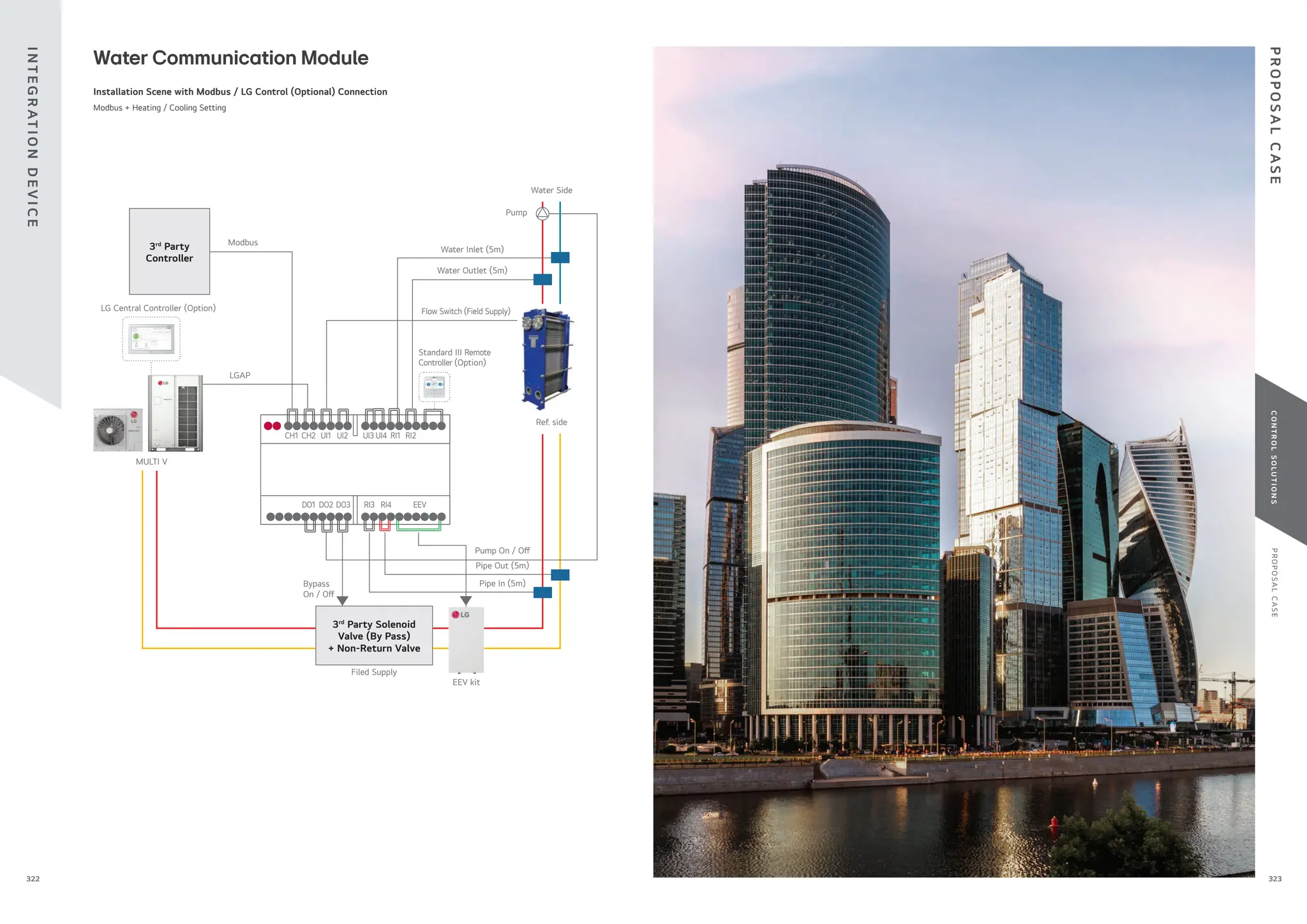


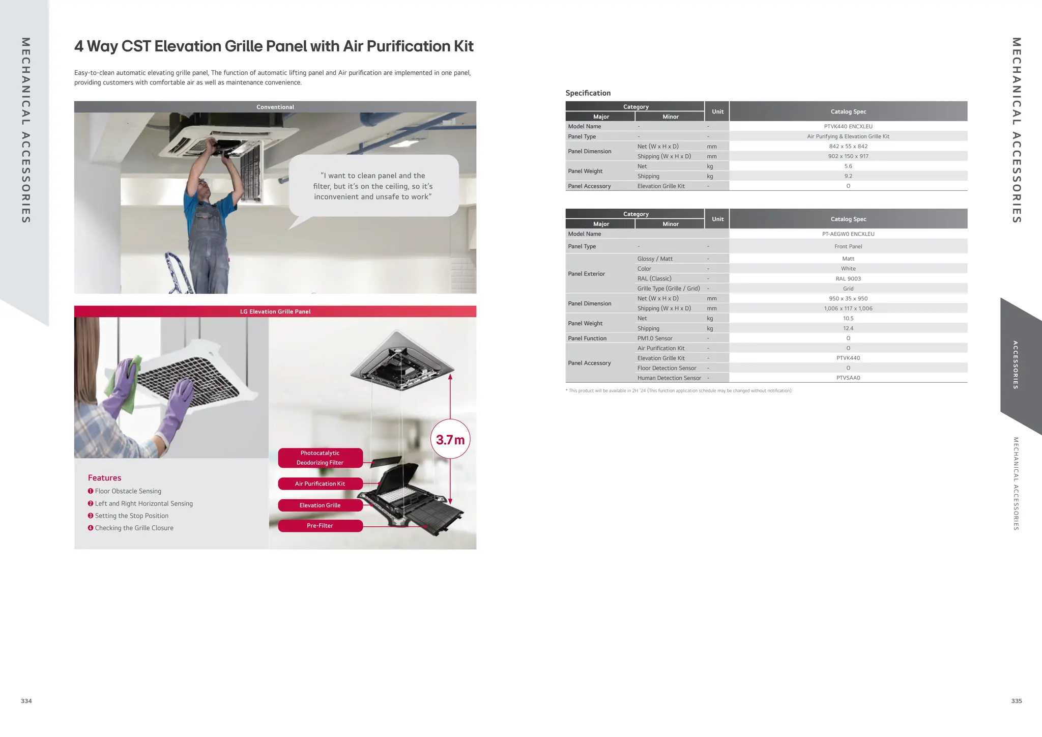
![M
E
C
H
A
N
I
C
A
L
A
C
C
E
S
S
O
R
I
E
S
A
C
C
E
S
S
O
R
I
E
S
337
336
PLDRNV1S
Model Name
MULTI V i R32
MULTI V S R32 (ZRU***)
Applied Products
• The green LED turns on in normal mode. If the detector is abnormal such
as “Leakage”
, “Malfunction” and “Lifetime”
, the red LED blink and buzzer
sounds simultaneously with error display on indoor units, wired remote
controller or central controller.
• “Leakage” alarm is “on” with “CH230” error display when refrigerant leaks
out more than 5,000ppm for 5 seconds. “Leakage” alarm is “o ” only
when the system reset.
• “Malfunction” alarm is “on” with “CH228” error display when the detector
determines failure.
• “Lifetime” Alarm is “on” with “CH229” error display when the used time
exceeds 3650 days.
• When the alarm of the refrigerant leak detector is switched on, the
occupants should be away from the site and supervisor must ventilate the
room until the alarm is disabled.
• The detector has to be installed inside the room and it should be installed
0.3~0.5m above the oor.
Key Features
R32 refrigerant leak detector should be needed to ensure occupant’s safety by IEC 60335-2-40 because of R32’s low- ammability.
Parts Speci cation
Sensor
Size (W x H x D, mm) 53.8 x 30 x 22
Weight (g) 12
Power Supply Voltage (V) 5.0 DC ± 5%
Average Power
Consumption (mA)
40 (Max. 80)
Certi cate
RoHS2, JRA 4068:2016R,
IEC60335-2-40 Ed6.0
Detectable Refrigerant R32
Alarming
Leakage (5,000ppm) /
Malfunction / Lifetime
Operation Temperature (°C) -25 ~ 60
PCB Assembly
Buzzer Noise Level (dB(A)) 85
LED
Green (Normal) /
Red (Alarming)
Connecting
Cable
Length (m) 10
Sensor
Protective Case
Plate Dimension (Front / Back)
(W x H x D, mm)
66 x 89 x 46 /
66 x 89 x 16
※ Error can be displayed on some indoor units such as Wall-mounted, Ceiling Mounted Cassette etc.
※ Sound level can vary depending on the installation condition.
Speci cation Included Parts
R32 Refrigerant Leak Detector
Sensor Assembly
Screws
Case
Connecting Cable
Screws
Installation Manual
PRLDNVS0
Model Name
MULTI V i
MULTI V 5
MULTI V IV Heat Pump & Heat Recovery
MULTI V WATER 5
Applied Products
• This detector senses refrigerant leakage when the refrigerant
concentration exceeds 6,000ppm. (The green and red LED lights blink
simultaneously.)
• Alarm is “on” when refrigerant leaks out more than
6,000ppm for 5 seconds. If it is reduced less than
6,000ppm for 5 seconds, alarm is “o ”
.
• When the alarm of the refrigerant leak detector is switched on the user
must ventilate the room until the alarm is disabled.
• The detector has to be installed inside the room and it should be installed
300 ~ 500mm above the oor.
Key Features
R410A refrigerant leak detector ensures room safety.
Parts Speci cation
Sensor
Rated Voltage (V) DC 5.0 5%
Dimensions
(W x H x D, mm)
31 x 44 x 20
Weight (g) 22
Detectable Refrigerant R410A
Detected concentration
(ppm)
0 / 6,000 Alarm O / On
Operating temperature
range (oC)
-10 ~ 50
Preserved temperature
range (oC)
-40 ~ 60
Average power consumption
(mA)
35
Connecting cable Cable length (m) 10
Sensor protective
cover
Dimensions of Front Plate
(W x H x D, mm)
80 x 110 x 44.6
Dimension of Backplate
(W x H x D, mm)
80 x 110 x 6.5
This function available for ARU****L**5 and 4 (MULTI V i, MULTI V 5, MULTI V IV H/P, H/R model)
Speci cation Included Parts
Sensor Connecting Cable Sensor Protective
Cover
Refrigerant leakage detector has application methods. (LG system complies with IEC 60335-2-40)
Key Application
Room 3 Room 4
Room 1 Room 2
• Stop the leakage IDU and close the a ected shut-o valves.
Operate other IDUs.
(In case that the operation setting is “OP3”
.)
Room 3 Room 4
Room 1 Room 2
• Close all shut-o valves inside the HR unit and operate
a ventilation fan.
Room 3 Room 4
Room 1 Room 2
• Close all shut-o valves inside the HR unit and operate
a ventilation fan.
Refrigerant Leak Detector
Refrigerant leak detector has three application methods.
Key Application
Room 3 Room 4
Room 1 Room 2
Case 1)
Stop Operating
(System Termination)
Room 3 Room 4
Room 1 Room 2
Case 2)
Main Pipe Closing &
Pump Down
Accessory Speci cation (To realize the case 2 application)
I/O Module
PVDSMN000
※ Necessary
accessory
1) Please contact to subsidiary
to get the recommended
speci cation. (LG Electronic
don’t provide this accessory)
[Optional / Field Supply]
Automatic
Ball Valve1)
[Field Supply]
Buzzer alarm for room
Central Control
Devices
PDRYCB400
(Dry contact)
[Optional / Field Supply]
Buzzer alarm
for central control room
(Direct connection ~
DC 30V, ~ 1A)
PRLDNVS0
(Refrigerant
leak detector)
Room 3 Room 4
Room 1 Room 2
Case 3)
Branch Pipe Closing &
Continuous Operating
M
E
C
H
A
N
I
C
A
L
A
C
C
E
S
S
O
R
I
E
S
M
E
C
H
A
N
I
C
A
L
A
C
C
E
S
S
O
R
I
E
S
Enhanced Tightness Refrigerating System
+ Safety Devices (Shut-o Valve + Alarm)
Enhanced Tightness Refrigerating System
+ Safety Devices (Alarm + Ventilation)
Enhanced Tightness Refrigerating System
+ Safety Devices (Alarm + Ventilation)
Remote
Controller
Remote
Controller
Remote
Controller
Remote
Controller
Remote
Controller
Remote
Controller
Refrigerant
Dectector
Refrigerant
Dectector
Refrigerant
Dectector
Refrigerant
Dectector
Refrigerant
Dectector
Refrigerant
Dectector
Card Key Card Key Card Key
Buzzer Alarm Buzzer Alarm
I/OModule
Valve
Valve
Valve
Valve
Buzzer Alarm
Buzzer Alarm
Refrigerant Leak Refrigerant Leak Refrigerant Leak
Buzzer Alarm Buzzer Alarm
Ventilation
Ventilation
Dry Contact Dry Contact Dry Contact](https://image.slidesharecdn.com/240222lgmultivcataloguelow-251206043823-67e9ad80/75/240222-LG-Multi-V-Catalogue_low-pdffdffdffdwfdfdsfdfewffgegg-169-2048.jpg)


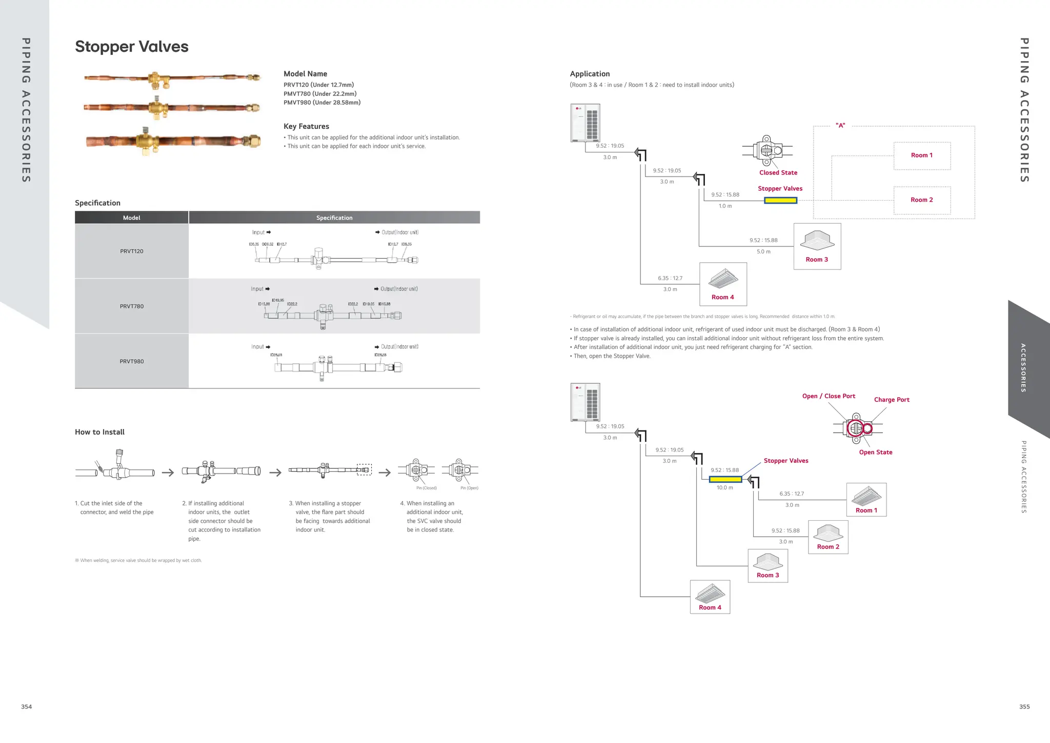


![MULTI V 5 Catalogue_Small[20231107_182247769].pdf](https://cdn.slidesharecdn.com/ss_thumbnails/multiv5cataloguesmall20231107182247769-240307050612-24907867-thumbnail.jpg?width=640&height=640&fit=bounds)


