This document describes a study submitted for a Master's degree in Information Technology. The study focuses on generating IEEE/ISO 42010-2011 compliant views of URDAD platform-independent models with a graphical syntax. Quality requirements for the graphical syntax are defined based on principles of effective visual notation design. Graphical modelling tools are developed and evaluated based on these principles to implement views for URDAD service contract and data structure specifications. The tools aim to make the URDAD language more accessible for practitioners.


![Chapter 1
Introduction and
Background
1.1 Introduction
The increase in scale of software systems and the rapid growth in their
complexity greatly increases the potential of errors occurring in the design
and construction of software systems [20]. Errors have the potential to be
particularly costly since the cost of errors is compounded as software tran-
sitions through the phases of software development [61]. According to Gilb
and Finzi (1988) correcting errors during design is ten times less expensive
than during the development phase and a hundred times less expensive than
fixing an error once the system has been deployed [29].
1.1.1 Formal Methods
Formal methods have been developed to address some of these concerns. In
particular, they illuminate inconsistencies, ambiguities and the incomplete-
ness of systems [20]. Formal methods facilitate the construction of reliable
software. Formal methods aim to achieve this through providing unam-
biguous requirements in addition to designs capable of being proven to be
accurate and reliable [46]. However, the perception of formal methods has
been that they are very expensive [33] and generally do not scale up well
from small-scale applications [37].
1.1.2 Model Driven Engineering (MDE)
The challenges surrounding formal methods have resulted in the develop-
ment of a range of semi-formal methods capable of retaining the benefits
of formality whilst addressing concerns regarding complexity and cost [14].
Model Driven Engineering (MDE) approaches fall within the class of semi-
formal methods. MDE is an overarching paradigm of software development
11](https://image.slidesharecdn.com/1e64cc26-cc26-48de-bf94-dbb7eebda95f-170126105214/85/22024582-12-320.jpg)
![vested in the exploitation of domain models. MDE proposes a promising
approach to generative techniques, specifying the realisation of executable
models that are based on formal semantics [45].
1.1.3 Model Driven Architecture (MDA)
The Object Modelling Group (OMG) has attempted to realise the concept
of MDE through Model Driven Architecture (MDA). MDA is supported by
a set of OMG standards [43] which can be implemented to produce tools
that facilitate the application of MDE. MDA reduces complexity by sepa-
rating the functional and non-functional requirements of systems in order to
address the different aspects of a system independently [64]. MDA achieves
the separation through the representation of a system at a higher level of
abstraction where implementation details can be disregarded [64]. MDA
captures these requirements without the need to commit to a technology
platform [64]. The concept of a Platform Independent Model (PIM) in
MDA, realises the higher level of abstraction by representing the functional
requirements of a system [25].
1.1.4 Use Case, Responsibility Driven Analysis and Design
(URDAD)
The OMG offers an approach to MDA as well as standards for tool sup-
port. The OMG provides guidance instead of prescribing, and accordingly
MDA does not specify the model structure of source models and does not
prescribe any methodology for analysing and designing them. URDAD pro-
vides a services-oriented analysis and design methodology which can be used
to generate an MDA PIM [70]. The URDAD methodology provides domain
experts with the ability to model requirements in a technology-neutral man-
ner [70]. It provides a simple, repeatable manner in which to generate MDA
PIM’s allowing functional requirements to remain technology neutral [70].
URDAD bolsters its formal aspects through model verification and a formal
model structure specification [71].
URDAD PIMs have been documented utilising the Unified Model Lan-
guage (UML) due to the wide adoption and corresponding tool support
throughout the software industry [68]. This has proven complex as, in addi-
tion to the lack of a defined model structure capable of sufficiently express-
ing the constraints of a valid URDAD PIM, UML lacks support for certain
URDAD concepts [68]. The wide variation in model structure and content
permitted by UML contributes to the difficulty in generating an URDAD
PIM [71]. The difficulty results from the increased complexity of imple-
mentation mapping [71] caused by the lack of structure and wide variation
in permitted model content. Further, the UML specification lacks a stan-
dard notation for rendering precondition and postcondition [71] constraints
12](https://image.slidesharecdn.com/1e64cc26-cc26-48de-bf94-dbb7eebda95f-170126105214/85/22024582-13-320.jpg)
![in the context of URDAD. This is required for rendering an URDAD PIM
and places a dependency on supporting tools. The lack of such tool support
requires the practitioner to populate dependency relationships directly on
the model [71].
1.2 Problem Background
Model-driven approaches to software development have the advantage that
the business requirements exist within the model [27]. The model is, in ef-
fect, the business requirement [27] and vice versa. Changes to requirements
are implicitly reflected in the model, which ensures integrity between the
model and requirements [27]. In addition, a model-driven approach pro-
vides a platform for generating tool support to further simplify requirement
specification [27].
Using models in software engineering has several advantages, including:
• reuse at the design level,
• reduced system complexity,
• reduced coding costs,
• reduced testing costs,
• reduced documentation costs, and
• increased maintainability and enhanceability [24].
MDA is a framework that provides way of automating the generation of
applications from models [41] and aims to improve productivity, portability,
interoperability, and quality of software [41]. MDA also promotes the sepa-
ration of technology and business requirements [41], and as stated by Ma et
al. (2009) is complementary to a Service-oriented Architecture (SOA) ap-
proach [41]. MDA achieves this separation of business requirements from its
implementation technology in the form of a PIM [64]. Technology changes
do not affect the PIM, and the impervious nature of the PIM toward change
extends the Return on Investment (ROI) of modelled requirements [6]. MDA
thus facilitates the generation of independent components capable of outliv-
ing one another through change [41].
URDAD subscribes to a service-oriented approach to requirement solici-
tation [68]. It integrates a service-oriented approach with MDA [68]. In the
context of MDA URDAD is used to generate a PIM [70]. URDAD specifies
service contracts across levels of granularity [68]. Service contracts specify
non-functional requirements in terms of quality requirements and functional
requirements in terms of preconditions and postconditions [68]. Services at
13](https://image.slidesharecdn.com/1e64cc26-cc26-48de-bf94-dbb7eebda95f-170126105214/85/22024582-14-320.jpg)
![a higher level of granularity can consist of other services, thus forming a
functional composition [68].
Previous attempts at service-oriented design methodologies have em-
ployed Business Process Model and Notation (BPMN) in order to model
processes [49, 41], and in addition have been technology specific [71]. Al-
though BPMN is reasonably capable of business process specification across
levels of granularity, its constrained semantics limits BPMN to the sufficient
design of technology-neutral business processes amenable to Model Driven
Development (MDD) [70]. BPMN does not support robust service contract
specification or data structure specification [70] and does not require a design
approach to be service-oriented [25].
The benefits of adopting URDAD include:
• increased productivity resulting from a systematic approach and the
ability to disregard non-functional requirements,
• an established standard of output from the analysis and design process,
produced with improved quality and consistency, and
• the potential of the requirements produced to retain relevance that
transcends the implementation technology [70].
As previously mentioned, URDAD PIMs have been visualised using UML
due to wide industry adoption and the extensive tool support that the lan-
guage enjoys [68]. UML supports many of the elements required by UR-
DAD including technology-neutral business process design [70], service con-
tract specification (using compound activities in conjunction with the Object
Constraint Language (OCL)) and data structure specification [70].
UML is sufficient for depicting relationships as well as, to a degree, stake-
holders [68]. UML does not provide support in terms of linkages between
stakeholders [68]. In addition, the UML specification does not specify any
standard notation for rendering constraints. As stated earlier, UML repre-
sentations may also be complex due to the large number of entities contained
within the language [71]. UML does not provide a notation for specifying
services conveniently and is unable to represent dependencies between ser-
vices, which significantly impedes its ability to populate URDAD PIMs [70].
In general UML is not that accessible to business stakeholders and is
difficult to understand and work with [76]. Visual representations and views
of UML models are provided in order to overcome the usability issues [76].
There is no clear indication of how the large number of diagrams (13 different
types in UML 2.0 [76]) are related to one another [76].
A UML profile (such as the UML profile for Enterprise Distributed Ob-
ject Computing (EDOC) [76]) restricts the number of diagrams and UML
elements [71] to a small but sufficient subset of UML and provides struc-
ture to a valid UML model. A UML profile is also capable of introducing
14](https://image.slidesharecdn.com/1e64cc26-cc26-48de-bf94-dbb7eebda95f-170126105214/85/22024582-15-320.jpg)
![concepts required by URDAD [68]. Constraints can enforce and restrict a
model structure to the extent that it is capable of representing a UML model
as a valid URDAD PIM [71]. An URDAD UML profile however, requires
an excessive number of constraints in order to structurally comply with an
URDAD PIM [68].
The output of the URDAD methodology is a model complying with the
URDAD meta model [68]. A meta model logically defines the modelling ele-
ments used within a modelling notation [9]. A meta model is often referred
to as an abstract syntax [31]. It specifies the semantics and structure with
which a model must comply in order to be valid. An abstract syntax does
not however prescribe a method of concrete model construction.
A Domain-Specific Language (DSL) is a language designed
to be useful for a specific set of tasks [31]
Solms et al. (2011) have defined the URDAD DSL for the domain of
technology-neutral service-oriented requirements modelling [68]. The UR-
DAD DSL facilitates technology-neutral, service-oriented requirements mod-
elling and enhances the ability of practitioners, using the URDAD method-
ology, to document requirements in models [68]. The URDAD DSL enforces
a valid model structure by limiting constructs to those congruent with the
URDAD meta model [68]. This renders many constraints required by the
URDAD UML profile superfluous and provides a more conducive environ-
ment for tool-supported model validation [68]. In addition to enforcing a
valid model structure, the URDAD DSL is simpler than UML and provides
better support for depicting URDAD concepts than UML [68] as it is specif-
ically designed for this purpose.
A DSL’s structure is captured in its abstract syntax [31]. The URDAD
DSL’s abstract syntax is described in terms of Ecore, the Eclipse Modelling
Framework’s (EMF)’s implementation of the OMG’s Essential Meta Object
Facility (EMOF) [68]. EMOF is a smaller subset of the OMG’s Meta Object
Facility (MOF) standard for defining meta models and provides a language
for defining the abstract syntax of modelling languages [74] such as that
of the URDAD DSL. MDA relies on EMOF/MOF for its modelling aspect
[6] and because the URDAD DSL is described in an EMOF/MOF based
implementation, the URDAD DSL is capable of populating an MDA PIM.
In order for an abstract syntax of a DSL to be represented for use by
humans, one or more concrete syntaxes must be developed [31]. Models
constructed from a concrete syntax are referred to as instance models [31].
A concrete textual syntax for URDAD is proposed by Solms et al. (2011)
which enables practitioners to specify requirements from an URDAD PIM
[68]. The textual syntax is regarded as too technical for many industry
practitioners [68]. In addition, a textual syntax has other detracting features
when compared to a graphical representation.
15](https://image.slidesharecdn.com/1e64cc26-cc26-48de-bf94-dbb7eebda95f-170126105214/85/22024582-16-320.jpg)
![Text is extremely constrained when compared to graphical representa-
tions [54]. Although the linear character of text is restricting, it aids in
conveying meaning to the reader when the secondary notation is dysfunc-
tional [54]. At the other extreme of freedom a graphical representation is
more susceptible to conveying an incorrect meaning and confusing the con-
sumer [54].
The definition of a usable concrete graphical syntax has been identified
as a critical success factor for the URDAD methodology [68]. A concrete
graphical syntax safeguards the validity of the model by limiting constructs
to its ontology set [73]. The restrictive nature of such a syntax also ensures
that it is easier to learn [73] by prohibiting invalid relationships and ensuring
that construct definitions are complete and valid. Tooling capable of sup-
porting the concrete syntax aids in safeguarding the population of a valid
model. This attribute contributes to the critical success factor of usability
[68]. This project defines a concrete graphical syntax for a subset of elements
in the URDAD meta model. In addition, tooling capable of supporting the
concrete graphical syntax is developed.
The graphical syntax is used in generating diagrams of URDAD PIM’s.
Different diagrams represent different views of the underlying model [31].
With large, complex models, such as that of URDAD, multiple diagrams, or
views, of the model are often required [31]. Each view focuses on represent-
ing one concern addressed by the model. This makes it easier to understand
and work with the model. The issue of synchronisation is raised when deal-
ing with multiple views, as changes to the diagram should be reflected in the
underlying model and vice versa. When multiple models are involved the
complexity increases in mapping different views to different models for syn-
chronisation. However, with URDAD there is only one underlying model
that is represented from various perspectives and thus synchronisation is
simplified.
As mentioned earlier, MDA is non-prescriptive as to the structure of
model specification. The IEEE/ISO 42010-2011 specification, however, pro-
vides us with a standard for documenting models [10] in the form of a set of
requirements that architecture descriptions must adhere to. The IEEE/ISO
42010-2011 specification is very abstract and does not prescribe a method
of producing architectural descriptions [10]. Nor does it prescribe any mod-
elling methods or notations in order to produce architecture descriptions
[10].
The standard requires that an architecture description consist of one or
more views [10]. A view addresses one or more stakeholder concerns [10],
with each view complying with the specifications of a viewpoint [10]. A
viewpoint ensures that a view addresses stakeholder concerns by framing
them and establishing conventions by which the view is generated [10]. A
viewpoint frames one or more stakeholder concerns, and a concern can be
framed by more than one viewpoint [10]. The concept of a viewpoint is
16](https://image.slidesharecdn.com/1e64cc26-cc26-48de-bf94-dbb7eebda95f-170126105214/85/22024582-17-320.jpg)
![already employed in the definition of a concrete textual syntax for the UR-
DAD DSL [68]. In particular, the URDAD DSL text syntax specifies data
structure, service contract and service viewpoints, with the latter containing
the process specification for a service realizing a service contract.
The concerns addressed in this project are the data structure specifica-
tion and service contract specification. This project defines the viewpoints
that are leveraged in order to produce views capable of addressing these
stakeholder concerns.
1.3 Problem Definition
The development of a concrete textual syntax for the URDAD DSL enabled
practitioners to leverage off the advantages of using models in requirement
specification. The URDAD DSL, through its ability to support service-
oriented, contracts-based requirement specification, provides a simpler way
than the use of UML to populate models. As stated earlier, the textual
syntax is deemed too technical for practitioners [68].
A graphical notation can be developed for a DSL, and can then be
mapped onto its abstract syntax in order to produce a concrete graphi-
cal syntax. A concrete graphical syntax can provide a visual programming
interface [73] which greatly enhances the usability of a DSL. It can signif-
icantly reduce cognitive load [47] by taking advantage of the benefits of
convey information through visual representations.
The definition of a concrete graphical syntax for the URDAD DSL is
required in order for it to be rendered diagrammaticality. The URDAD
methodology envisages requirements specialists, from various responsibility
domains, contributing to a single requirements model [68]. Subsets of the
URDAD DSL identified for graphical representation, that are in alignment
with the concrete textual syntax are the service contract view and data
structure view [68]. The full semantic coverage of the elements of the UR-
DAD DSL that each view consists of is required in order to maintain the
integrity of the model. The identification of suitable graphical notation qual-
ity requirements is paramount in order to assess its capability to effectively
convey information.
The application of the graphical syntax will be significantly simplified
with the support of tooling capable of populating an URDAD PIM. This will
allow the implementation of the concrete graphical syntax while preserving
the integrity of the URDAD PIM through the application of bi-directional
binding to the model and any representations (from various perspectives)
of the model. The complexity of using the URDAD DSL for requirement
specification is significantly reduced by defining a concrete graphical syntax
as well as developing tooling capable of implementing the syntax.
17](https://image.slidesharecdn.com/1e64cc26-cc26-48de-bf94-dbb7eebda95f-170126105214/85/22024582-18-320.jpg)
![1.4 Purpose of the Study
In the first place this study aims to generate graphical representations of
an MDA PIM constructed using the URDAD DSL. In the context of the
IEEE/ISO 42010-2011 specification the model is represented from two per-
spectives that address specific stakeholder concerns [10]. The focus of this
project is the representation of a single URDAD PIM from various per-
spectives in the form of views. The perspectives identified for URDAD are
the data structure viewpoint, the service contract viewpoint and the service
viewpoint that contains the process specification. This study focuses on the
data structure and service contract viewpoints.
The generation of a concrete graphical syntax that corresponds to the
URDAD meta model is required for each view. Secondly, this project aims
at full semantic coverage of the elements in the URDAD meta model that are
required to represent the respective views. This will allow for the preserva-
tion of the model’s integrity when it is altered diagrammatically. The third
aim of the project is to identify criteria for the evaluation of the effective-
ness of the defined graphical notation proposed for these views. In the fourth
place the study aims to develop corresponding tooling, which implements
the concrete graphical syntax to support practitioners in the application of
the URDAD DSL. In order to demonstrate the graphical notation as well as
the tooling, the concrete graphical syntax is applied in visually representing
a non-trivial example of an URDAD PIM.
1.5 Significance of Study
This study will contribute to the field of service-oriented design, and more
particularly to the application of the theory of diagrammatic languages to
service-oriented design. The outcome of this study covers the URDAD DSL
but could be re-purposed on a much wider scale, i.e. a graphical syntax
rooted in well researched quality requirements could be reused in other
graphical representations of Ecore constructed meta models. Furthermore,
adhering to standards compliant with MDA allows the resultant model to
be used in the Eclipse Graphical Modelling Project (GMP) tool suite.
This project should significantly lower the barrier to entering into the
MDA space by enhancing the URDAD DSL’s usability. It is envisioned
that a usable graphical syntax will facilitate the adoption of URDAD. An
intuitive graphical notation should enable a larger audience to work with
the URDAD methodology in requirements modelling.
A graphical syntax prevents the practitioner from straying from valid
model constructs, enforces the integrity of the graphical representation. A
lack of tooling capable of providing guidance for this syntax is another factor
hindering the adoption of URDAD in commercial applications. The tooling
18](https://image.slidesharecdn.com/1e64cc26-cc26-48de-bf94-dbb7eebda95f-170126105214/85/22024582-19-320.jpg)
![developed in this project aims to make it less complex to adopt the method-
ology by enabling domain specialists to more easily construct valid URDAD
PIMs which can then further be employed for model validation, code and
test generation and documentation generation. Generating the visual repre-
sentations based on a common meta model that enjoys widespread support
provides us with a wide range of applications. In this instance the URDAD
DSL conforms to the EMF supported Ecore meta model.
1.6 Scope and Limitations
The scope of this project pertains to the generation of two IEEE/ISO 42010-
2011 compliant views of an MDA PIM described using the URDAD DSL.
The IEEE/ISO 42010-2011 specification provides us with the concept of
models that describe the architecture of a system and views of models that
address various stakeholder concerns [10]. MDA proposes a way to harness
models in systems development [64, 25]. The URDAD methodology provides
us with a practical means of constructing an MDA PIM [70] that describes
the functional requirements of a system separately from the non-functional
requirements [68]. The two concerns identified for the generation of views
are the service contract specification and the data structure specification
[68]. For each of these concerns a corresponding view is generated with a
corresponding concrete graphical syntax defined.
Congruent to the IEEE/ISO 42010-2011 standard, the first of the two
graphical representations is the service contract view. It governs the
requirements a service needs to meet in order to sufficiently provide a par-
ticular service. These include the preconditions and postconditions of the
service [68]. The second is the data structure view. It defines the rela-
tionships between data structure objects and their composition [70] within
a responsibility domain, as well as the composition of the input and output
required of a service so that they conform to the service’s service contract
[68].
Each view will require its own graphical notation which will be mapped
onto the existing DSL constructs and evaluated against quality requirements
for graphical notation design. Evaluations of requirements engineering no-
tations are often conducted based on semantics [48]. This project focuses
on the design rationale of the graphical notation, since the URDAD DSL is
concerned with the semantic coverage required to produce a complete and
valid model that adheres to the URDAD meta model.
The DSL’s abstract syntax is specified in Ecore. We will be using the
Graphical Modelling Framework (GMF) to generate the diagrammatic syn-
tax for each view, as well as the corresponding tooling to support the de-
velopment of a concrete graphical syntax. The project does not include the
model-to-model transformations required to generate other models from an
19](https://image.slidesharecdn.com/1e64cc26-cc26-48de-bf94-dbb7eebda95f-170126105214/85/22024582-20-320.jpg)
![URDAD PIM and will focus on the visualisation of an already constructed
MDA PIM described using the URDAD DSL. Further research can be done
to promote the universality of the URDAD analysis and design methodology.
The main focus of this research project is the practitioner. The re-
duced complexity and increased formality of the URDAD methodology are
expected to enhance and expedite their capabilities in requirements specifi-
cation.
1.7 Method
1.7.1 Quality Requirements for the Concrete Graphical Syn-
tax
This project aims to generate a concrete graphical syntax that will reduce
the complexity of working with the URDAD DSL in requirements modelling.
In notation design the most effort usually goes into the definition of the vi-
sual language constructs and what they represent [48]. The main focus is
often on ensuring the graphical notation is ontologically complete, which
results in the visual notation often being neglected [48]. Since this project
aims to reduce complexity, focus on the graphical notation is paramount.
This endeavour places certain quality requirements on the development of
a graphical syntax, quality requirements capable of providing guidance in
defining a simple, intuitive notation that reduces the complexity of em-
ploying the URDAD DSL in modelling an URDAD PIM. The criteria for
a reduction in complexity are intuitiveness, simplicity and practicality. If
they are met, ease of use in requirements solicitation using the URDAD
DSL should be increased. Quality requirements for the definition of graph-
ical notations are identified for this purpose. The industry-wide acceptance
of these quality requirements will contribute towards an intuitive graphical
syntax.
1.7.2 Approach and Implementation
The URDAD DSL is defined in terms of the Ecore model. Ecore is the
Eclipse Modelling Framework’s (EMF) implementation of EMOF [31] (a
smaller version of MOF). A common meta model has been identified as a
critical factor for the successful adoption of Model Driven Software Develop-
ment (MDSD) [31]. The Ecore model serves as this common meta model for
MDA tool suites, thus providing us with the ability to generate a concrete
graphical syntax and provide tool support for meta models conforming to
EMOF [68].
The Eclipse Modelling Project (EMP) encompasses smaller projects that
provides support for abstract syntax definition as well as concrete syntax de-
velopment [32]. A prerequisite for technologies used for practising MDA is
20](https://image.slidesharecdn.com/1e64cc26-cc26-48de-bf94-dbb7eebda95f-170126105214/85/22024582-21-320.jpg)
![the implementation of OMG standards [32]. EMP largely supports OMG
standards and encourages the practice of MDA since many of the projects
conform to MDA specifications. The MOF (and EMOF) specification forms
the basis of the OMG standards for MDA in addition to transformation
standards such as Query/View/Transformation (QVT) [31]. The OMG stan-
dards do not, however, support the specification of concrete syntaxes.
The GMF project supports concrete graphical syntax development through
the definition of a graphical notation for a DSL. In GMF the graphical nota-
tion is defined independently of the DSL constructs. The graphical notation
is then mapped to the DSL in the mapping model. The meta model is an in-
tegral part of the implementation. It requires an Ecore model at the nucleus
of the GMF workflow for tool generation.
The modelling tools are envisioned as being realized through the pro-
duction of a plug-in for the Eclipse IDE, such as the GMF based diagram
editors. In the process of the development of such a tool-set there is an
implicit requirement to use the already developed Ecore domain model in
defining a concrete graphical syntax amenable to EMF and its projects. The
URDAD DSL forms the basis of this endeavour.
1.7.3 Assessment
The concrete graphical syntax defined for each view is evaluated against the
design goal of cognitive effectiveness. The speed, ease, and accuracy of the
graphical syntax’s application are assessed against principles that influence
each of these factors. There is the potential for conflict in assessing the
graphical syntax against the same criteria guiding its definition.
This possibility can be excluded because 1.) the principles are univer-
sally accepted (widely known) and 2.) there is a trade-off in the extent to
which each principle is applied (see chapter 3). Some of the principles are
competing and therefore it is impossible to fully adhere to all the principles
equally in defining a graphical notation.
The complexity of developing an URDAD PIM using the concrete graph-
ical syntax is assessed against the identified quality requirements. The prac-
ticality and usability of the graphical notation is evaluated through its ap-
plication to a non-trivial example, which is enabled through the tooling
developed in support of the graphical syntax.
1.8 Summary of Results and Achievements
A literature review of quality requirements for graphical notation design is
conducted. A concrete graphical syntax is developed for a subset of the UR-
DAD DSL, namely the service contract and data structure specifications.
These specifications correspond to viewpoints that govern the construction
of views, as defined by the IEEE/ISO 42010-2011 specification for describing
21](https://image.slidesharecdn.com/1e64cc26-cc26-48de-bf94-dbb7eebda95f-170126105214/85/22024582-22-320.jpg)
![Chapter 2
Related Work
2.1 Formal, Informal and Semi-formal Methods
Research conducted by Zhivich and Cunningham (2009) shows that the cost
of addressing software issues, including re-installing infected systems where
vulnerabilities were exploited, amounts to $60 billion annually (in 2009) in
the United States [78]. Apart from the cost implications of errors, these
errors could prove fatal when human life relies on software systems [46].
The software engineering discipline emerged in response to technical and
economical challenges [46]. Software engineering attempts to enable the con-
struction of reliable software amid their ever increasing complexity and scale
[20]. The earlier shortcomings in a software system are detected, the greater
the financial benefit due to the reduction in the cost impact in subsequent
phases of software development [61, 29].
Formal methods specify and verify systems using the mathematically
based languages, tools and techniques that support their construction [20].
The transfer of formal methods from research to practice has been slow
for software [21]. The wide-spread adoption of more formal methods in
software development is prevented by the model construction problem [21].
The construction of models from implementations is challenging due to the
semantic gap between the languages used in implementations and those re-
quired by verification tools [58]. General-purpose programming languages
allow developers to produce artefacts far removed from the requirements
of model verification tools [58]. Model verification tools mostly accept in-
put described in language specifications designed for simplicity [21]. The
validation of models thus requires the error-prone and time-consuming [21]
transformation of the implementation to an abstraction that contains its
salient properties, specified in the input language accepted by the verifi-
cation tool [58]. Formal methods assist in the provision of unambiguous
requirements and design that is reliable and that can be verified [71].
MDE falls within the class of semi-formal methods [69]. Semi-formal
23](https://image.slidesharecdn.com/1e64cc26-cc26-48de-bf94-dbb7eebda95f-170126105214/85/22024582-24-320.jpg)
![approaches provide some structure to support a certain level of model vali-
dation and transformation [71]. Semi-formal approaches are not as complex
as formal approaches, with the result that some of the certainty that formal
approaches can provide is sacrificed.
2.2 Model Driven Engineering (MDE)
MDE promises to reduce the costs involved in software development [31]
through reducing the effort expended in gathering requirements for the con-
struction of a domain model and automating software construction. MDE
provides us with a manner of practising software development, driven through
domain models [45]. Domain models are capable of outliving the infrastruc-
ture they are implemented in as they are platform-independent and can be
reused and implemented in different technologies [66]. As domain models are
technology neutral, they allow us to conform to the IEEE/ISO 42010-2011
standard for software specification.
Staab et al. (2010) surveyed MDE with ontology technologies and assert
that for the sufficient specification of formal semantics that conform to a
meta model, close alignment to the meta model specification is required
[74]. A modelling language is defined as consisting of an abstract syntax
with one or more concrete syntaxes and corresponding semantics [74]. In
this project our meta model is the URDAD DSL which is closely aligned
to its meta model specification (described using EMOF) [68]. Modelling
tools are capable of supporting model validation [74] which is one of the
capabilities of the tooling developed in this project.
2.3 Model Driven Development (MDD) and Model
Driven Architecture (MDA)
Concrete implementations of MDE such as MDD has not been widely adopted
and is mostly utilised in the instances where problems are safety critical and
reliability is vital [71]. Reasons listed are:
• the lack of a clear definition of the requirements for specifying an
MDA1 PIM,
• a lack of standards to define the implementation architecture and the
accompanying technologies required to map implementations, and
• a lack of well-defined, practical analysis and design methodologies that
specify the artefacts to be included in the PIM [71].
1
the OMG’s version of MDD
24](https://image.slidesharecdn.com/1e64cc26-cc26-48de-bf94-dbb7eebda95f-170126105214/85/22024582-25-320.jpg)
![In MDA, a Platform-Specific Model (PSM) represents non-functional re-
quirements [25]. A PIM is mapped to a PSM of the different implementation
architectures and technologies according to defined model transformations
[70]. A PSM includes sufficient implementation details to convert the model
to a particular source code implementation [64]. This is referred to as MDD.
MDA provides the environment where a PIM is transformed into a PSM [64].
Both formal and agile methods have influenced MDD [71]. Formal meth-
ods strive to enable the verification of software specifications and develop-
ment and to prove their correctness and reliability [20]. MDD aims to cap-
ture and maintain business processes by an abstraction depicted in models
[62]. MDD’s essential departure point is that software development focuses
on constructing models rather than programs which are deemed as a technol-
ogy specific side effect [62]. MDD is capable of simplifying the development
of software from volatile business processes [70]. The constant pressure of
change and the adaptation of business to the environment it operates in, re-
quire that change be handled effectively. In addition, working with models
provides us with certain benefits which are listed in table 2.1.
Table 2.1: Advantages of using models in software engineering
Concept Description
Direct representation A solution can be expressed directly in terms
of the problem domain [19]
Comprehension An abstracted model is easier to comprehend
than implementation code [19]
Documentation The model may prescribe how to build the
system, or describe how the system was built
[19]
Validation A model can be validated against design cri-
teria to ensure that the system can be built
[19]
Simulation A model of a system can be used to simulate
different scenarios and find the best solution
before the system is built [19]
Traceability A model can refer to other models or code.
Hence, information or changes in one model
can be traced to other models [19]
Automation Implementation code may be partly or com-
pletely generated from models. Hence, it may
speed up development time and reduce the
number of errors [19]
25](https://image.slidesharecdn.com/1e64cc26-cc26-48de-bf94-dbb7eebda95f-170126105214/85/22024582-26-320.jpg)
![MDA is the OMGs version of MDD [70]. The most important benefit
of MDA is the ability of the PIM to survive implementation technology
and infrastructural change [70]. These PIMs can then be mapped onto
technology implementations as required [71].
MDA complying models can be modelled using UML [71]. In addition,
MDA is capable of meta language specification via the Meta-Object Facil-
ity (MOF) and supports constraint specification through OCL [71]. Model
querying and transformation are supported via the Query-View Transfor-
mations (QVT) specification [71].
Fatwanto and Boughton (2008) present a method of composing Archi-
tectural Descriptions suitable for MDD that comply with the IEEE/ISO
42010-2011 specification [10, 26]. A distinction is made between a logical
and an architectural viewpoint where the logical view describes the func-
tional features and the architectural view the platform [10]. They depict
these models using the Executable Translatable UML (xtUML) Class Di-
agrams and further demonstrate the capabilities of mapping languages to
their views [26].
In research by Fink et al. (2004) the generation of PSMs from PIMs is
explored [27]. An MDD approach is taken to develop access control policies
for distributed systems [27]. OCL is employed to represent constraints in
the PIM [27]. Meta models are constructed based on the MOF specification,
similarly to the URDAD DSL. Meta models are visually represented [27] yet
there is no graphical syntax definition and accordingly no tool support.
Other emerging disciplines have benefited from the use of MDA. Accord-
ing to Leist and Zellner (2006) the development of enterprise architecture
descriptions is challenging despite the many existing approaches [40]. The
broad scope and lack of structure developers are faced with are the most ap-
parent issues [40]. MDA provides enterprise architecture with an approach
that overcomes many of the obstacles faced, such as being capable of gener-
ating a specification document, based on a meta model, with roles defined
through prescribed techniques [40].
2.4 Service-Oriented Design Methodologies
An MDA approach aims to specify requirements separately from the tech-
nology used to implement the functionality [41]. A service-oriented approach
is capable of separating the business process from its implementation tech-
nology [41]. Accordingly, a service-oriented approach and MDA are comple-
mentary. There are, however, a very few methodologies that, like URDAD,
aim to integrate the MDA and service-oriented approaches in requirement
specification.
26](https://image.slidesharecdn.com/1e64cc26-cc26-48de-bf94-dbb7eebda95f-170126105214/85/22024582-27-320.jpg)
![2.5 Use-Case Responsibility Driven Analysis and
Design (URDAD) and UML
URDAD is a service-oriented analysis and design methodology [71]. UR-
DAD is technology neutral and requires analysis and design across levels of
granularity [71]. URDAD provides a means to realising the value of MDA
by bolstering its standards and providing a well-defined analysis and de-
sign methodology [71]. URDAD integrates with a model-driven approach
by providing a simple, repeatable manner in which to generate MDA PIMs
[71].
URDAD has been employed in conjunction with UML (see section 2.6)
[70], which is not ideal due to the wide variation allowed by UML in model
structure. In their research Wieringa et al. (2004) and Schippers et al.
(2005) attempt to overcome this obstacle by generating a UML profile in
order to mitigate the wide variety of the language used to depict domain
models [60, 76]. Wieringa et al. (2004) mapped their UML profile to the
Archimate meta model [76] that provides visualisation through tool support
and a visual notation to the model. Similarly a corresponding concrete
graphical syntax is defined yet it diverges from the project in this paper in
that the syntax is not based on an MDA supported standard but on UML.
A general-purpose language such as UML does not constrain the PIM
and hence needs to be used with discipline in order to produce valid models.
UML models can be constrained with the use of OCL [68]. An excessive
number of constraints would, however, be required [68]. OCL is also not
suited to constraining a model in a service-oriented context, because it can-
not sufficiently specify a constraint on state that is not accessible via an
object graph [68].
The characteristics of URDAD are stepwise refinement of requirements
and design, with well-defined inputs and outputs per step, service contract
generation in levels of granularity, and an explicit approach to fixing the lev-
els of granularity whilst still remaining technology neutral [70]. The stan-
dardisation in design method eases the mapping of the PIM to the PSM
upon implementation.
Obstacles encountered that relate to the practical application of the UR-
DAD methodology include:
• a reluctance to use UML for documenting business processes,
• difficulty in discerning the boundary between the business process and
the technology employed, and
• a lack of understanding of the methodology that leads to varying and
low-quality results in requirement specification [70].
27](https://image.slidesharecdn.com/1e64cc26-cc26-48de-bf94-dbb7eebda95f-170126105214/85/22024582-28-320.jpg)
![2.6 Domain-Specific Languages (DSL)
An URDAD PIM can be captured in a generic modelling language like UML
[70]. URDAD is not, however, restricted to any particular modelling lan-
guage [70]. A modelling language only requires sufficient semantics capable
of documenting a PIM [70]. In order for a modelling language to support
URDAD it would need to be able to support technology neutral business
process, data structure and service contract modelling. It should also have
the capability to model layers of granularity of services and the ability to
indicate relationships between data structure objects and their composition
[70].
DSLs have met with limited success because:
• they are more expensive to create and maintain due to their limited
user community,
• consequently there is a lack of tooling and support when compared
with Generic Programming Languages (GPL), and
• the sheer size of the General Purpose Language (GPL) user base over-
comes the disadvantages of implementations, ensuring they are robust
and reliable [12].
A DSL enforces the structure of a model ensuring it produces a valid
model [31]. The DSL constrains the model constructs to only those avail-
able in the language capable of producing a valid model [68]. This aspect
makes working with DSLs simpler as it alleviates the burden of validation
for the practitioner, and with the appropriate tool support, facilitates the
construction of models by requirements engineers [68].
Skene and Emmerich (2006) have proposed that meta models should play
a much larger part in specifying requirements, arguing that meta models and
specifications should be combined in order to ensure integrity and eliminate
any ambiguity [65]. The paper proposes the use of a DSL integrated with
requirement specification [65]. Their proposed DSL is not conducive to spec-
ification in a service-oriented approach, yet it does have a concrete textual
syntax defined [65].
Zhaol et al. (2008) propose their own modelling language based on
principles similar to those of this project [77]. They leverage off the MOF
specification in defining their DSL [68, 77]. Their project also recognises the
principles of MDA. Like the URDAD DSL the XKL language is defined based
on the structure of EMOF, and they employ OCL to constrain models [77].
The abstract syntax of the XKL language is defined along with a concrete
textual syntax [77]. Their DSL does not cater for a service-oriented approach
nor is an attempt made to define a concrete graphical syntax [77].
Muller et al. (2008) propose a specification for generating concrete syn-
taxes that rely on meta models [51]. They leverage off meta models in order
28](https://image.slidesharecdn.com/1e64cc26-cc26-48de-bf94-dbb7eebda95f-170126105214/85/22024582-29-320.jpg)
![to produce tools capable of bi-directional model transformation between a
concrete and an abstract syntax [51]. Similar to the research in this paper
and aligning with MDA, their project leverages a meta model to produce a
concrete syntax [51]. However, they propose a concrete textual syntax [51]
as opposed to a concrete graphical syntax and they do not integrate service-
oriented design with an MDA approach [51]. As a corresponding concrete
textual syntax has already been developed for the URDAD DSL [68] we will
leverage off the existing meta model in order to define a concrete graphical
syntax.
Pons and Garcia (2008) propose an approach for validating generic mod-
elling language semantics. Therefore they do not leverage off a DSL specif-
ically constructed for their domain of discourse [55]. The method employs
UML as a modelling language and OCL in order to constrain and vali-
date models [55]. Similarly, Borges and Mota (2007) have integrated the
UML meta model with more formal methods by mapping it to the OhCir-
cus language [18] in an attempt to reuse existing tools based on widely
adopted standards. However, both these projects lacks support for mod-
elling a service-oriented approach [71] due to their use of UML.
2.6.1 IEEE/ISO 42010-2011
There are many definitions for software architecture. The definition chosen
for the purpose of this paper is by Solms (2012) who asserts that software
architecture is
. . . the software infrastructure within which application com-
ponents providing user functionality can be specified, deployed
and executed [67].
The definition relies on the definition of an application component [67].
Ambroziewicz and ´Smialek (2010) defines an application component as
. . . software components which address functional requirements
of the software system [15].
The definition makes a distinction between application design and ar-
chitecture design [67]. Application design is defined as design addressing
functional requirements, whilst architecture design addresses non-functional
or quality requirements [67].
URDAD is an architecture-neutral design methodology that aligns with
the definition of architecture as consisting of both the application design as
the functional requirements in business process specification and the recog-
nition of the architecture design in non-functional or quality requirements
[70]. URDAD focuses on the design of functional requirements.
29](https://image.slidesharecdn.com/1e64cc26-cc26-48de-bf94-dbb7eebda95f-170126105214/85/22024582-30-320.jpg)
![The IEEE/ISO 42010-2011 specification serves as a recommended prac-
tice for expressing the architecture of software-intensive systems [10]. It
facilitates the communication of architectures [10] and aims to address the
creation, analysis and sustainment of the architecture of software-intensive
systems. It focuses on the description of architectures and not on the con-
struction of their implementations. The IEEE/ISO 42010-2011 specification
is based on five core concepts and relationships that are in short: 1) every
system has architecture separate from the system, 2) architecture and the
description thereof are separated, 3) architectural standards, descriptions
and development processes are separated, 4) architectural descriptions can
be viewed from many angles, and 5) the view and the specification thereof
are separated as well. Maier and Rechtin (2000) clarify the separation be-
tween architecture and the system, stating that
. . . (a)n architectural description is a concrete artefact, but
an architecture is a concept of a system [42].
The IEEE/ISO 42010-2011 specification defines software architecture as
. . . fundamental concepts or properties of a system in its en-
vironment embodied in its elements, relationships, and in the
principles of its design and evolution [10].
The definition does not provide a definitive explanation of the fundamen-
tal concepts [67] of a system. The specification could apply equally to both
the application design (addressing functional requirements) and the archi-
tectural design (addressing non-functional requirements). The reasoning is
that in both application and architecture design the concept of populating a
model specified by views that comply with viewpoint specifications applies.
The specification also requires traceability of requirements back to design
decisions, which is again equally applicable to application and architectural
design.
Conceptual integrity is the binding principle of software, and software
architecture provides a defence against the decay of this integrity over time.
The IEEE/ISO 42010-20112 specification is an attempt at creating a com-
mon practice around the expression and communication of software-intensive
systems architectures in a structured manner [10].
The elements of Architectural Descriptions (AD) as defined by the IEEE/ISO
42010-2011 specification are: 1) stakeholders, 2) concerns, 3) architectural
views and 4) viewpoints. Stakeholders have an interest in a system. These
interests are expressed as concerns about the system’s architecture [10].
Functionality, performance, security and feasibility are concerns typically
encountered. Viewpoints frame concerns for meaningful descriptions of the
2
Compatible with other standards such as the ISO Reference Model-Open Distributed
Processing (RM-ODP)and architecture frameworks: C4ISR and DODAF [10].
30](https://image.slidesharecdn.com/1e64cc26-cc26-48de-bf94-dbb7eebda95f-170126105214/85/22024582-31-320.jpg)
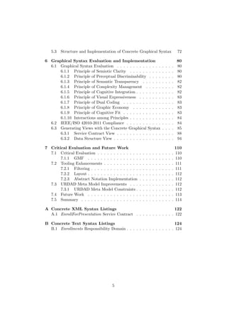
![Figure 2.1: The IEEE/ISO 42010-2011 conceptual model of an architecture
description
architecture. Views are representations of a set of elements within a sys-
tem and their associated relationships [10]. The concept of architectural
views has been embraced by modern software architecture. The IEEE/ISO
42010-2011 specification applies this concept and abstracts it further into
viewpoints [10] that serve as a convention for the construction of a view.
This practice provides us with reusable templates that assist in the stan-
dardisation of describing an architecture.
The IEEE/ISO 42010-2011 specification was designed to be method neu-
tral in its practice [10]. Therefore users are permitted to exploit any pre-
ferred method to construct architectural descriptions.
2.7 Other Service-Oriented Design Methodologies
A survey of service-oriented development methodologies conducted by Ramol-
lari et al. (2007) identified several methodologies of which many employ
UML and/or BPMN [57]. No reference is made to MDA integration nor to
a concrete syntax and corresponding tool support [57].
Karhunen (2005) presents a service-oriented software engineering (SOSE)
component framework [36]. It is similar to URDAD in its service-oriented
approach and integrates MDA as well [36]. This approach is, however, very
31](https://image.slidesharecdn.com/1e64cc26-cc26-48de-bf94-dbb7eebda95f-170126105214/85/22024582-32-320.jpg)
![conceptual and does not provide a usable abstract syntax [36] such as that
of the URDAD DSL.
Moosavi et al. (2009) propose a method for service-oriented design sim-
ilar to URDAD [49]. The project focuses on design and employs UML as
well as BPMN but does not provide an abstract syntax or the accompanying
tooling capable of supporting the design methodology [49].
Ma et al. (2009) propose an MDA based platform for service-oriented
applications [41]. It is similar to the project in this paper in that this project
also integrates a service-oriented approach with a model-driven approach
[71]. The project progresses further in that it has tool support capable of
facilitating its implementation in a proposed platform. However, the project
diverges from this paper in using UML 2.0 in order to depict certain views
[41]. It also diverges in the views that it proposes to aid in design [41]. The
project employs OCL [41]. The project includes the development of their
own modelling tool support that leverages off existing graphical notations
[41]. The tool is capable of translating the models into executable code,
similar to research done by Edwards (2011) [25].
Quartel et al. 2004 propose a service-oriented design process with an
accompanying modelling language, Interaction System Design Language
(ISDL) [56], comparable to the URDAD DSL. The project recognises the
need for a generic service-oriented design paradigm independent of an im-
plementation technology [56]. It does not, however, integrate with MDA
and its accompanying EMOF standard, and in addition does to not provide
any tool support [56].
In research by Benguria et al. (2006) a model-driven approach integrated
with a service-oriented approach is proposed [75]. Similar views are proposed
in their PIM4SOA research project [75] and, although the nomenclature dif-
fers, the concepts are closely aligned to the workflow steps identified in UR-
DAD [68, 75]. These concepts are service, process, information and quality
of service [7]. The views generated to address the concerns defined by these
aspects are:
• the information view, representing the higher level context of the views
and forming the basis of the subsequent views,
• the service view, representing the functional technology independent
requirements,
• the process view, representing interactions among services, and
• the quality of service (QoS) view, representing the non-functional as-
pects of the services described [7].
The information aspect aligns with the proposed data structure view,
and the service view can be related to the proposed service contract view.
32](https://image.slidesharecdn.com/1e64cc26-cc26-48de-bf94-dbb7eebda95f-170126105214/85/22024582-33-320.jpg)
![The PIM4SOA project has a defined meta model for a service-oriented ap-
proach as well as an abstract language expressed in the EMOF format [7].
The project similarly relies on EMF in order to provide tool support [7].
These aspects align the PIM4SOA project closely to this paper’s research
topic. The main divergence, apart from a different meta model employed
in each project, is that the PIM4SOA project employs a UML profile in
realising the visualisation of models. The PIM4SOA project also relies on a
single viewpoint against the two proposed in this project3.
Agrawal et al. 2003 [12] propose a framework for the development of
domain-specific graphical languages. The authors develop their own DSL -
MOLES with a graphical representation constructed through their Generic
Modelling Environment (GME) [12]. They employ OCL for defining con-
straints [12]. The project provides tool support for the development of DSLs
and consists of a modelling environment, meta modelling language, model
transformation engine as well as an execution engine for the model transfor-
mations [12]. The project employs the UML language in order to represent
models which lack support for conducting service-oriented analysis and de-
sign.
Delgado et al. (2010) propose a framework that, similar to URDAD,
implements service-oriented computing integrated with the MDA approach
[23]. The MINERVA framework is defined to support analysis and design
[23]. In terms of graphical representation of models the project diverges
from the project in this paper in that it employs BPMN and UML to model
business processes [23]. The project identifies the business process and the
service-oriented concerns and then goes on to define ontologies for each [23].
The project proposes tooling in order to provide automated transformation
between models [23].
G¨onczy (2007) propose the development of services independent of tech-
nology using the Service Component Architecture (SCA), but does not,
however, integrate it with an MDA approach [30]. SRML (a modelling
language for service-oriented systems [8]) is employed to describe services
in a technology-independent manner [30]. The project diverges from the
project in this paper in that it does not propose to define services using
a DSL based on MDA compliant standards and is not able to realise the
accompanying benefits. Like this paper G¨onczys project proposes tooling
developed in the Eclipse Modelling Framework (EMF) environment [30].
3
there are three viewpoints identified for URDAD in the data structure, service contract
and service viewpoints (which contains the process specification)
33](https://image.slidesharecdn.com/1e64cc26-cc26-48de-bf94-dbb7eebda95f-170126105214/85/22024582-34-320.jpg)
![2.8 Concrete Syntax Definition
2.8.1 Concrete Textual Syntax Generation
Staab et al. (2010) identify and discuss four constructs from Ecore as rele-
vant to defining an ontology in an MDE context, namely EClass, EAttribute,
EReference and EDataType [74]. A DSL for the URDAD methodology has
already been defined and includes these constructs aligned to the recom-
mendation by Staab et al. (2010) [74].
Heidenreich et al. (2009) propose a refined specification for deriving a
textual syntax from meta modelling languages automatically [35].They ar-
gue that graphical and textual syntaxes are complementary due to certain
attributes [35]. Graphical syntaxes are very capable of representing rela-
tionships as well as quantities [35]. Graphical representations also provide
the opportunity to zoom, allowing for a more comprehensible overview [35].
Textual syntaxes, however, constrain their consumption to a linear form and
ensure interpretation occurs sequentially [35]. A model expressed in a tex-
tual syntax is also more easily comparable to others through tool support
[35].
The URDAD DSL has an abstract syntax with a corresponding con-
crete textual syntax [68], and in this project a concrete graphical syntax is
defined for that abstract syntax. A concrete graphical syntax is suggested
to further simplify the requirement specification process using the URDAD
methodology.
2.8.2 Concrete Graphical Syntax Generation
Cranefield and Pan (2007) generate an ontology compliant with MDA for
use in transformation and analysis [22]. The project relies on the Resources
Description Framework (RDF) (a MOF based language similar to Ecore) for
depicting instance models [22]. The premise of the project is using existing
technologies, and in order to accomplish this the RDF standard was used.
RDF supports automated mapping of a MOF based meta model to the RDF
syntax [22], which serves as a generic DSL. Apart from the fact that this
approach is incapable of providing the associated benefits of modelling in
a DSL, it constrains the practitioner to RDF supported tooling only. The
graphical notation would have to coincide with a generic modelling language
(such as UML) which is incapable of effectively modelling a service-oriented
approach in analysis and design (as established in section 1.2).
2.9 Graphical Notation Design Principles
Notation is at the centre of concrete graphical syntax definition. A notation
provides identity to the representation and directly impacts the practical
34](https://image.slidesharecdn.com/1e64cc26-cc26-48de-bf94-dbb7eebda95f-170126105214/85/22024582-35-320.jpg)
![nature of its usability. The software engineering field has employed visual
notation to depict software programs since the 1940s with Goldstine and
von Neumann’s program flowcharts [47]. The advances in the field of visual
representation culminated in the industry standard software engineering lan-
guage, UML, defined as
. . . a visual language for visualizing, specifying, constructing,
and documenting software intensive systems [47].
While UML is widely adopted, the graphical notation transgresses cer-
tain good design principles, as identified by Moody (2009) [47]. This influ-
ences the intuitiveness of visual representations produced using UML.
Moody (2009) has conducted research on well developed visualisation
notations, based on earlier work done by Tufte [47], and identifies 10 prin-
ciples capable of providing guidance in the development of notations. This
research project applies good design principles to graphical notation design
to ensure intuitiveness.
He et al. (2007) proposes a meta model for defining graphical notations
that aims to address the problems that exist in 1. defining a notation, 2.
defining the location of relationships and 3. mapping the notation onto an
abstract syntax [34]. The meta model comprises three parts, namely:
1. basic figures and layouts,
2. location relations, and
3. syntax bridges [34].
Their project employs the PKU Meta Model Tool(PKU MMT), imple-
mented in the Eclipse platform, and provides a graphical editor for defining
a concrete graphical syntax for a corresponding abstract syntax [34]. Like
this study it also generates the accompanying tooling capable of supporting
the defined graphical syntax [34], but it differs in using UML [34]. Conse-
quently it does not provide a mechanism for use with service-oriented design
methodologies. It does however provide us with the guiding framework for
defining a graphical notation used in this study.
2.10 Concrete Graphical Syntax Definition
Staab et al. (2010) define the Web Ontology Language (OWL)4 DSL [2].
The DSL employs Ecore as its meta-modelling language [74]. EMOF is
an MDA standard and serves as the meta model for Ecore [31], it is thus
the meta-meta model for the DSL. URDAD’s DSL is similarly based on
4
OWL is not a real acronym. The language started out as the Web Ontology Language
but the Working Group disliked the acronym WOL[2]
35](https://image.slidesharecdn.com/1e64cc26-cc26-48de-bf94-dbb7eebda95f-170126105214/85/22024582-36-320.jpg)
![Ecore which aligns this project very closely with the research done by Staab
et al. (2010) [74]. They, however, employ UML as a concrete graphical
syntax [74]. Although the concrete syntax does not meet with the needs
of modelling requirements using a service-oriented approach, the framework
identified by Staab et al. (2010) runs parallel to the topic of research in this
paper [74]. The concrete syntax definition and tools capable of supporting
the syntax in this project are, however, divergent from those used in the
research done by Staab et al. (2010) [74].
Mum et al. (2010) investigate meta model architectures for language
specification [50]. They indicate that the OMG diagram execution standard
- UML Diagram Interchange (UML DI) - is not sufficient for defining diagram
presentations as it is not precise in defining the representation of a diagram
[50]. In motivating their architectural approach, they evaluate the OMG,
XMF, KM3, Kermeta, EMF and GMF approaches [50]. Their findings are
that there are benefits to the Kermeta as well as to the GMF architectural
approaches in that they are:
• clear,
• flexible, and
• more extensible [50].
2.11 Tooling in Support of Concrete Graphical Rep-
resentations for DSLs
Research in the field of service-oriented design methodologies, such as that
by Moosavi et al. (2009) has not produced any supporting tooling [49].
Akehurst and Patrascoiu (2004) researched OCL 2.0 and have provided
a means of applying the language to any object-oriented language such as
EMOF [13]. They provide a bridge for meta models to EMF, among others
[13]. Other tooling identified that is not able to sufficiently meet the tooling
requirements of this project includes the PIM4SOA project [7], the MIN-
ERVA framework of tools [23], G¨onczy’s proposed EMF based tooling [30]
and the PKU MetaModel Tool (PKU MMT) implemented in EMF proposed
by He et al. (2007) [34]. The incompatibility stems from a variety of fac-
tors, including an incompatible meta model and meta model based standard,
and the inability to sufficiently model requirements from a service-oriented
approach.
36](https://image.slidesharecdn.com/1e64cc26-cc26-48de-bf94-dbb7eebda95f-170126105214/85/22024582-37-320.jpg)
![Chapter 3
Defining Quality
Requirements for Graphical
Notations
3.1 Quality Requirements of Graphical Notation
Design
Graphical notations are ingrained in the communication of information within
the software engineering discipline [47]. They play a critical role in commu-
nicating with practitioners such as users and customers. Visual represen-
tations are, however, just as vulnerable to the distortion of an information
message as other forms of communication [54]. Therefore quality require-
ments are needed to guide the definition of graphical notations.
A concrete graphical syntax, also known as a graphical notation1, is
widely employed in requirements engineering [48]. Text is more constrained
due to the one dimensional approach to conveying information inherent in
its linear character [54]. Information is believed to be conveyed more ef-
fectively to those less technically inclined in graphical than in text format
[47]. However, there are certain risks involved with representing informa-
tion graphically, as greater freedom increases the potential for miss-cuing
and confusion [54].
The benefits of visual representations include:
• more efficient information processing [47],
• concise communication of information [47],
• more precisely conveyed information [47],
1
also referred to as a visual notation, a diagram notation or visual language.
[48]
37](https://image.slidesharecdn.com/1e64cc26-cc26-48de-bf94-dbb7eebda95f-170126105214/85/22024582-38-320.jpg)
![• that they are more likely to be remembered due to the picture superi-
ority effect,
• that diagrams can group related information, which reduces the need
to search for elements [39],
• that diagrams can use more dimensions to convey information (e.g.
location of symbols and their labels) [39], and
• that diagrams support a large number of perceptual inferences that
come natural to humans [39].
The design rationale of a visual notation justifies the symbols chosen to
perceptually represent the semantics of a visual language [47]. Graphical
symbols are the visual vocabulary of the semantic constructs they represent
[47]. Compositional rules form the visual grammar which together with
the visual vocabulary forms a concrete visual syntax [47]. The semantic
constructs we will represent are contained within the URDAD DSL.
A concrete graphical syntax requires the definition of graphical symbols
that are then mapped to the constructs they represent [47]. These symbols
can then be depicted (using the visual vocabulary) in a manner that conforms
to the compositional rules (visual grammar) to form a diagram [47].
Moody [47] states that in order to effectively define a graphical notation
a design goal should be clearly defined. Our aim is to allow practitioners to
easily work with the URDAD DSL. Our design goal is reduced complexity.
This is however vague and difficult to evaluate empirically. A more descrip-
tive definition of our design goal is Cognitive effectiveness, defined as the
speed, ease, and accuracy of processing of a representation by the human
mind [47]. Cognitive effectiveness ensures that a visual notation facili-
tates communication between practitioners, and supports their design and
problem solving ability. Moody (2009) asserts that a graphical syntax not
only contributes to aesthetics but to effectiveness as well, since form has a
profound influence on cognitive effectiveness in relation to content [47].
Absolutely paramount to graphical notation design is the comprehension
of how and why visual notations convey information. Understanding the
guiding principles allows us to improve on visual notations [47]. In order to
provide traceability in the graphical notation design process and justify the
final design we will provide a design rationale for design decisions.
3.2 Challenges in Graphical Notation Design
Ontological Analysis
Ontological analysis assesses the appropriateness of a modelling grammar
[28]. The semantic comparison of an ontology with its modelling gram-
mar serves to minimise the subjectivity of evaluating a notation [28]. The
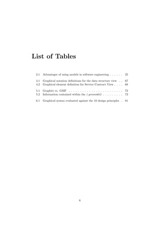
38](https://image.slidesharecdn.com/1e64cc26-cc26-48de-bf94-dbb7eebda95f-170126105214/85/22024582-39-320.jpg)
![Bunge-Wand-Weber (BWW) (see figure 3.1) ontology is widely used [47]
and provides us with an ontology capable of assessing the suitability of a
notation according to ontological fit [28].
ontology modelling grammar
(1)
(4)
(2)
(3)
(1) construct deficit
(2) construct redundancy
(3) construct overload
(4) construct excess
representation mapping
interpretation mapping
Figure 3.1: Ontological analysis
Ontological analysis involves the one-to-one mapping of the graphical
notation constructs to the modelling grammar [47] and can produce the
following anomalies:
• Construct deficit occurs if there is no construct in the notation that
corresponds to an ontological concept [28], in which case the notation
is ontologically incomplete [47].
• Construct overload occurs when a notational construct is capable
of representing multiple ontological concepts [28], so it becomes onto-
logically unclear [47].
• Construct redundancy is the inverse of construct overload and oc-
curs when multiple notation constructs are capable of representing an
ontological concept [28], in which case the notation is again ontologi-
cally unclear [47].
• Construct excess occurs when there is no mapping between a no-
tational construct and any ontological concept [28], in which case the
notation is ontologically unclear [47].
39](https://image.slidesharecdn.com/1e64cc26-cc26-48de-bf94-dbb7eebda95f-170126105214/85/22024582-40-320.jpg)
![Communication of Visual Notations
Moody (2009) adapts the widely accepted theory of communication by Shan-
non and Weaver [63] to the domain of visual notation, stating that the en-
coding and decoding processes of communication need to be leveraged in
order to ensure that information is correctly conveyed [47]. The creation of a
diagram is regarded as the encoding for which the visual notation is used,
and the decoding is the interpretation of that diagram by the intended
audience [47]. In the domain of visual notation the encoding process refers
to the design of the graphical notation using graphical design variables, and
the decoding process refers to the interpretation of the notation influenced
by principles of graphical information processing [47].
3.3 Graphical Design Variables
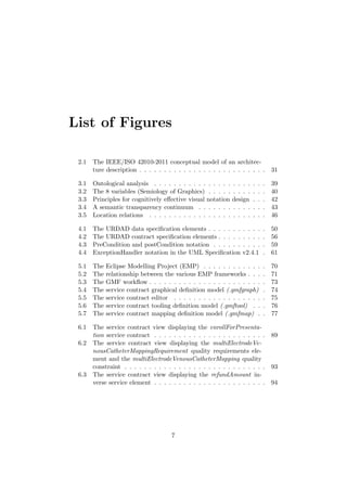
In Semiology of Graphics, Bertin (1983) defines eight visual variables used
to define graphical information [17] (see figure 3.22). These variables can be
used to define the primary notation which indicates the formal meaning of
symbols and a secondary notation that informally emphasises or communi-
cates information [54], e.g. boldface text or a darker shade of colouring to
indicate importance.
VL]HYDOXH KXH RULHQWDWLRQWH[WXUH VKDSH SRVLWLRQ
Figure 3.2: The 8 variables (Semiology of Graphics)
Secondary notation is non-trivial and complements perceptually the in-
formation conveyed symbolically [54]. According to Shannon and Weaver’s
communication theory [63], visual noise is unintentional or random varia-
tion in visual variables that conflicts with or distorts the information con-
veyed [47]. The primary meaning falls within the scope of this project with
the influences of the secondary meaning considered where appropriate.
2
taken from Miller (2004) [44]
40](https://image.slidesharecdn.com/1e64cc26-cc26-48de-bf94-dbb7eebda95f-170126105214/85/22024582-41-320.jpg)
![3.4 Graphical Information Processing
A distinction is made between two phases when humans process graphi-
cal information. The first is perceptual processing, followed by cognitive
processing [47]. Perceptual processing is automatic and natural, making it
faster and less resource intensive as it is unconscious, whereas cognitive pro-
cessing involves understanding and analysing the information in a conscious
manner (this requires effort). Thus the effectiveness with which graphical
information is processed is largely determined by the exploitation of percep-
tual processing [47]. The stages in human graphical information processing
need to be considered in order to promote the optimal use of perceptual
processing.
The stages in human graphical information processing are identified as:
• perceptual discrimination, the play between visual variables that
allows one to discriminate between symbols,
• perceptual configuration, the interpretation and detection of the
patterns or structures in which symbols are organised,
• attention management, the conscious effort lent to the active pro-
cessing of elements,
• working memory, the limited capacity that is available at a spe-
cific point, and which influences the capability of active information
processing, and
• long-term memory, the integration of processing with prior knowl-
edge [38].
3.5 Principles for Cognitively Effective Visual No-
tation Design
In designing an effective visual notation certain factors need to be brought
into consideration, namely the recognisability of symbols, principles for con-
veying information through visual communication, secondary and primary
notation, and the possible redundancy of information that could lead to
misinformation [31]. The stages of human graphical information processing
are considered in identifying principles capable of guiding visual notation
design.
The use of filters and layers, layout, synchronisation and the depiction
and indication of relationships between graphs and sub-graphs, congruent
with the analysis of levels of granularity, require consideration in the devel-
opment of supporting tooling [31].
41](https://image.slidesharecdn.com/1e64cc26-cc26-48de-bf94-dbb7eebda95f-170126105214/85/22024582-42-320.jpg)
![Figure 3.3 depicts principles for cognitively effective visual notation de-
sign. The 10 design principles outlined by Moody [47] are listed and dis-
cussed briefly.
Cognitive
Integration
Visual
Expressiveness
Dual Coding
Graphic
Economy
Cognitive Fit
Interactions
among
Principles
Interactions
among
Principles
Semiotic
Clarity
Perceptual
Discrimina
bility
Semantic
Transpare
ncy
Complexity
Manageme
nt
Cognitive
Integration
Visual
Expressive
ness
Dual
Coding
Graphic
Economy
Cognitive
Fit
Figure 3.3: Principles for cognitively effective visual notation design
Principles for Designing Cognitively Effective Visual Nota-
tions
1. Principle of semiotic clarity
2. Principle of perceptual discriminability
3. Principle of semantic transparency
4. Principle of complexity management
5. Principle of cognitive integration
6. Principle of visual expressiveness
7. Principle of dual coding
8. Principle of graphic economy
42](https://image.slidesharecdn.com/1e64cc26-cc26-48de-bf94-dbb7eebda95f-170126105214/85/22024582-43-320.jpg)
![9. Principle of cognitive fit
10. Interactions among principles
3.5.1 Principle of Semiotic Clarity
The principle of semiotic clarity extends ontological analysis to apply to a
visual syntax [47]. In order to adhere to this principle, a 1:1 correspondence
between semantic constructs and graphical symbols is required [47]. Should
a 1:1 correspondence not be maintained, the semiotic inconsistencies of sym-
bol redundancy, symbol overload, symbol excess and symbol deficit could
occur [47].
3.5.2 Principle of Perceptual Discriminability
In order to leverage off perceptual processing, clearly distinguishable sym-
bols are required to minimise cognitive load [47]. Visual distance, shape,
redundant coding, perceptual pop-out and textual differentiation contribute
to perceptual discriminability [47].
3.5.3 Principle of Semantic Transparency
The appearance of visual representations should suggest their meaning [47]
through relying on mnemonics [54].
Semantically Immediate
• Infer correct meaning from
appearance alone
Semantically Opaque
• Arbitrary learned relationship
Semantically Perverse
• Meaning misinterpreted
Semantic Translucency
Figure 3.4: A semantic transparency continuum
Often referred to as ’intuitiveness’, semantic transparency reduces cog-
nitive load by relying on the previously-learned or easily and accurately
perceived associations between objects and functions [54]. A figure is said
to be semantically immediate if its meaning can be inferred correctly
from its appearance alone [47]. At the other end of the scale a figure is said
to be semantically perverse if the meaning of the figure is misinterpreted
[47]. Should ambiguity exist toward the meaning of a figure it is said to
43](https://image.slidesharecdn.com/1e64cc26-cc26-48de-bf94-dbb7eebda95f-170126105214/85/22024582-44-320.jpg)
![be semantically opaque. With semantically opaque figures meaning is
attached to the figure by a learned connotation as there is no reliance on
pre-existing connotation. The degree to which a figure meets the require-
ments on the continuum is referred to as its semantic translucency. Semantic
transparency is applied principally in the use of icons and relationships [47].
3.5.4 Principle of Complexity Management
Explicit mechanisms should be employed to effectively manage complexity
[47]. In order to prevent cognitive overload and accommodate perceptual
limits, modularisation as well as hierarchical structuring is employed. The
separation between the service contract view and data structure view can
be deemed modularisation of the URDAD PIM. Responsibility domains in-
troduce a hierarchical structure that requires representation in each of the
views.
3.5.5 Principle of Cognitive Integration
Explicit mechanisms should be employed to support information integration
from various diagrams [47]. Closely related to complexity management, this
principle applies when multiple diagrams are used to represent concepts.
It applies where mental integration of information needs to occur between
diagrams. An example would be the service contract element that requires
representation in both the service contract and data structure view. Con-
ceptual integration and perceptual integration are employed to assist.
3.5.6 Principle of Visual Expressiveness
The eight visual variables3 are capable of promoting visual expressiveness
[47]. Their full range and capacities are exploited to this end.
3.5.7 Principle of Dual Coding
When conveying information effectively the use of text and graphics is not
mutually exclusive. The dual coding theory [52, 53] states that using both
together is more effective than each on its own. This principle promotes the
use of text to complement graphics [47], but substituting graphics with text
is discouraged. The use of annotations and hybrid graphics in a diagram
are examples of this principle.
3
Semiological variables: Planar: Horizontal and vertical position and Retinal: orien-
tation, shape, texture, brightness, size, and colour. [17]
44](https://image.slidesharecdn.com/1e64cc26-cc26-48de-bf94-dbb7eebda95f-170126105214/85/22024582-45-320.jpg)
![3.5.8 Principle of Graphic Economy
Graphical symbols should not be so numerous as to be cognitively unman-
ageable [47]. Ways in which graphical complexity can be managed are
through a reduction (partitioning) in semantic complexity, by introducing
symbol deficit4, and increasing visual expressiveness. These options compete
with many of the principles that are employed to increase the practitioner’s
ability to discriminate between graphical representations. This points to the
interaction between principles and emphasises the balance that needs to be
maintained when applying these principles due to their ability to influence
each other’s effectiveness.
3.5.9 Principle of Cognitive Fit
Cognitive fit refers to the suitability of the representation of information, in
terms of either the task at hand or the intended audience [47]. Cognitive fit
can be increased through different visual dialects that depend on the skills
levels of practitioners [47]. Taking into account the representational medium
such as the task, as well as the salient characteristics that influence its
interpretation, ensures that the cognitive fit is increased [47]. This principle
suggests the use of different visual notations for each respective task or
audience in order to promote a better cognitive fit [47].
3.5.10 Interactions among Principles
The 10 principles (see figure 3.3) are not necessarily complementary and
some do conflict. Principles interact and taking this into account is paramount
in making trade-offs in situations where principles compete [47]. Principles
can also complement each other and can be wielded to enhance each other’s
effectiveness.
3.6 Defining Notations for Graphical Modelling
Languages
He et al. (2007) propose a meta model for defining graphical notations,
namely the Notation Definition Meta model (NDM) [34]. The meta model
is comprised of three parts:
1. Defining Basic Figures and Layouts
2. Defining Location Relations
3. Specifying Syntax Bridges
4
see semiotic clarity in section 3.5.1
45](https://image.slidesharecdn.com/1e64cc26-cc26-48de-bf94-dbb7eebda95f-170126105214/85/22024582-46-320.jpg)
![3.6.1 Basic Figures and Layouts
Figure designs need to be concise as this makes them easy to implement in
tools [34]. Figures are composed of basic figures which combine the rectan-
gle, rounded rectangle, diamond, triangle, polygon, ellipse, circle, straight
line, polyline, arc, text object and image [34]. Layout is paramount as ex-
plained by Gronback (2009):
Layout can go a long way toward making diagrams more read-
able and can even convey semantic information [31].
Layout aids in depicting parent and child relationships and includes flow
layout, border layout, decoration layout, role name layout, vector-graph
layout and extendible layout [34]. An ontological fit is required to allow the
sufficient mapping of notational constructs to the modelling language [47].
3.6.2 Location Relations
Location relations communicate additional information regarding the dif-
ferent structural relationships between meta-classes [34]. These are classi-
fied into nested type, connected type, port type, node-attached type and
end-attached type [34](see figure 3.5). This aspect relates to the secondary
notation [54] and aids in the cognitive efficiency of the notation.
nested type end-attached typeconnected type port type node-attached type
A
B
C
BA BA
B
A
A
C
Figure 3.5: Location relations
3.6.3 Syntax Bridges
The graphical notation serves as the concrete syntax of a modelling language
[34]. Syntax bridges are used to describe mappings between the graphical
notation and modelling language constructs (or abstract syntax) [34] and
ensure that there is an ontological fit.
The three syntax bridges are:
• model mapping, the mapping between modelling elements and no-
tation elements,
• attribute mapping, the manner in which attribute values are dis-
played, and
46](https://image.slidesharecdn.com/1e64cc26-cc26-48de-bf94-dbb7eebda95f-170126105214/85/22024582-47-320.jpg)
![• relationship mapping, the mapping between meta-class relation-
ships and location relations [34].
47](https://image.slidesharecdn.com/1e64cc26-cc26-48de-bf94-dbb7eebda95f-170126105214/85/22024582-48-320.jpg)
![Chapter 4
Graphical Syntax Definition
4.1 A Framework for Graphical Notation Defini-
tion
He et al. (2007) [34] identify steps in defining a graphical notation [34],
namely:
1. defining a notation,
2. defining the location of relationships, and
3. mapping the notation onto an abstract syntax [34].
These steps are followed in order to define a graphical syntax for the
URDAD DSL.
4.1.1 Defining a Notation
Defining a notation requires the identification of the semantic constructs
required to sufficiently represent a coherent model. The traceability and
consistency of the syntax depends on the 1:1 mapping of a construct to its
notation.
The URDAD meta model is specified in the Ecore format [68]. Ecore is
an implementation of EMOF [31] and can be leveraged to define the meta
model of a DSL [25]. The Ecore meta model hence serves as a meta model
for defining meta models, i.e. it is a meta-meta model. Elements from the
URDAD DSL, defined in the Ecore format, represent the semantic constructs
for which a graphical syntax is defined.
4.1.2 Defining the Location of Relationships
The principles identified by Moody (2009) (see Chapter 3), are employed
to guide the definition of the graphical notation as well as the layout for
48](https://image.slidesharecdn.com/1e64cc26-cc26-48de-bf94-dbb7eebda95f-170126105214/85/22024582-49-320.jpg)
![each semantic construct to be represented [47]. The layout or location of
relationships refers to how figures interact throughout the various that are
layers capable of displaying them, e.g. overlapping or nesting figures, con-
nection ports and proximity of descriptive labels among others (see figure
3.5). The importance of these factors is recognised and coincides with the
quality requirements identified. Specifically, the semiological variables that
constitute visual expressiveness (see 3.5.6) contribute toward location re-
lationships. Location relationships are implicitly addressed in defining the
graphical notation when guided by the good design principles identified by
Moody [47].
4.1.3 Mapping the Notation onto an Abstract Syntax
The assignment of each figure (model, attribute, and relationship mapping)
is displayed in a tabular format with examples capable of conveying the
graphical notation. The notation of each semantic construct, as well as
location relations, is presented.
4.1.4 UML
URDAD PIMs have been populated using UML with a class and an activity
diagram, among others [71]. A class diagram is useful in depicting service
contracts and the activity diagram for representing the process specification
[71]. With UML, however, a construct deficit [47] is encountered regard-
ing service constraints [71]. UML does not provide a notation for rendering
constraints. In addition to the construct deficit [47], there is a seman-
tic deficit when using UML (with OCL) for service-oriented modelling. In
particular, OCL allows one to construct constraints across an object graph
[68]. In a service-oriented approach, the post-conditions for a service need to
be specified in terms of results from other services. For example, the post-
condition for an enrolStudentForModule service might be that a subsequent
request for getEnrolledStudents for that module should return a collection
of students which contains student x. OCL on its own is semantically insuf-
ficient to specify such a constraint.
Consequently, using a UML class diagram with an interface and pre-
and post-conditions on the services is both semantically incomplete and a
notation which is ontologically incomplete [47]. Defining a graphical syntax
capable of sufficiently representing an URDAD PIM requires a 1:1 mapping
of the semantic constructs required to represent a view.
The wide adoption of UML provides us with the challenge of an estab-
lished convention when defining a graphical notation. Defining a notation as
closely aligned as possible to convention reduces cognitive load. The trade-
off is that this does not always contribute toward the visual expressiveness
of the notation. The same is applicable to semantic transparency. For exam-
49](https://image.slidesharecdn.com/1e64cc26-cc26-48de-bf94-dbb7eebda95f-170126105214/85/22024582-50-320.jpg)
![ple, in certain diagrams UML provides us with the least cognitively effective
convention for representing cardinality as it relies on text alone to convey
information [47]. Another example would be where UML employs very sim-
ilar notations with vastly divergent semantics [47]. The balance between the
familiarity of this manner of expressing cardinality and the cognitive load of
learning new symbols has to be considered in defining a concrete graphical
syntax for the URDAD meta model. The OMG’s 2011 UML Specification
v2.4.1 [72] provides us with guidance in aligning with the well established
and widely adopted UML notation.
4.2 Defining a Notation
The principle of semiotic clarity (see 3.5.1) requires a 1:1 mapping between
semantic constructs and the graphical symbols defined to represent them
[47]. The definition of the URDAD DSL has led to the identification of the
semantic constructs required to represent a particular view. The graphical
notation can then be based on the elements identified from the DSL’s spec-
ification. Elements required for the representation of a particular view span
the different modules of the URDAD meta model.
When defining a graphical notation, Gronback (2009) recommends lever-
aging off known notations where possible [31]. The reasoning is that certain
figures and shapes already have meaning associated with them [31]. This
recommendation is in line with the concept of cognitive load and is one of
the guiding principles for defining a graphical notation [47]. The more fa-
miliar the syntax is, the closer it aligns to established meanings that are
associated with these figures. This results in greater semantic transparency
and a reduction in cognitive load [47].
4.2.1 The Data Structure View Requirements
Figure 4.1: The URDAD data specification elements
The data module of the URDAD DSL allows for an object-oriented ap-
proach to data structure specification [68]. This aligns with UML class
descriptions [68]. Figure 4.1 depicts all the necessary constructs of the UR-
DAD DSL required for the data structure view.
50](https://image.slidesharecdn.com/1e64cc26-cc26-48de-bf94-dbb7eebda95f-170126105214/85/22024582-51-320.jpg)
![Contract elements require a notation in the data structure view.
Elements of the URDAD DSL modules that require graphical represen-
tation are listed below, each with a corresponding graphical notation used
in populating the data structure view.
• DataStructure
The UML Specification v2.4.1 [72] provides us with a notation for a
class as a figure. The figure makes provision for the Name attribute
(derived from NamedElement) in a text format. In accordance with
the principle of semantic transparency (see section 3.5.3) and according
to Gronback (2009) using an existing notation among diagrams facili-
tates cognitive integration [31, 47]. Using simple shapes promotes the
principle of graphic economy [47] and makes them easier to implement
in tools [34].
• Attribute
The UML Specification v2.4.1 [72] provides us with a notation for an
Attribute element that is associated with a DataStructure element.
This is depicted via a class notation as in the DataStructure figure.
The Attribute name property is visible on the left of the semicolon
with the BasicDataType (discussed later) depicted on the right of
the semicolon. The principles of dual coding [47] and complexity man-
agement [47] guide the definition of this notation. The attributes are
located on the rectangle in a separate compartment, which increases
the perceptual discriminability [47] of the notation.
• RangeMultiplicity
The UML Specification v2.4.1 [72] recommends that multiplicity bounds
be depicted in the format: <lower-bound> .. <upper-bound>. Range-
Multiplicity can be depicted within a textual specification (e.g. adding
trailing multiplicity to the associated element name: ”Association
Name [1..*]” ) or as an adornment to a symbol.
Symbol adornment is employed in the data structure view in order to
leverage off the principle of perceptual discriminability [47]. Visual
52](https://image.slidesharecdn.com/1e64cc26-cc26-48de-bf94-dbb7eebda95f-170126105214/85/22024582-53-320.jpg)
![distance and redundant coding are used to convey meaning in terms
of text and the position of the constraint.
• Many
The Many element indicates an unspecified upper boundary and the
UML Specification v2.4.1 [72] makes provision for depicting this with
a ’*’ (see RangeMultiplicity). The same notation is employed in
this graphical syntax.
• BasicDataType
In representing the BasicDataType element a basic yet visually dis-
tinct rounded rectangle with a lighter border and the type name is
employed. Again the principle of perceptual discriminability [47] is
applied to facilitate the cognitive effectiveness of the notation. Per-
ceptual processing [47] is thus reduced by using a unique shape.
• Identification
The Identification element represents a relationships between DataS-
tructure elements and is implicitly represented by the specialised As-
sociation, Aggregation, and Composition elements and does not
require a notation.
• Association
The UML Specification v2.4.1 [72] depicts relationships through con-
nector figures. The existing UML Association element is employed.
An arrow indicates the direction of the relationship. The left element
has a relationship to the element on the right. The element on the
right is thus referenced by the element on the left.
53](https://image.slidesharecdn.com/1e64cc26-cc26-48de-bf94-dbb7eebda95f-170126105214/85/22024582-54-320.jpg)
![An existing notation promotes the principle of semantic transparency
[47]. The figure should however be visually distant enough to promote
perceptual discriminability [47].
• Aggregation
As for the Association element, the UML Specification v2.4.1 [72]
Aggregation notation is employed.
The arrow in the notation has the inverse meaning as the diamond
shape indicates what element is referenced. The arrow indicates the
element containing the reference.
The figure employs the same perceptual discriminability principle [47],
yet needs to be visually distant enough from an Association to pro-
mote perceptual discriminability [47]. The same applies to the Com-
position figure.
• Composition
The UML Specification v2.4.1 [72] Composition notation is em-
ployed.
The diamond shape is filled in order to easily distinguish visually be-
tween Aggregation and Composition. The arrow in the notation
is again the inverse of the Association, similar to the Aggregation
notation, thus maintaining the convention.
• superTypes
The UML Specification v2.4.1 [72] provides for a generalization rela-
tionship and has a corresponding notation that can be employed for
the superTypes element.
54](https://image.slidesharecdn.com/1e64cc26-cc26-48de-bf94-dbb7eebda95f-170126105214/85/22024582-55-320.jpg)
![The principles of semantic transparency [47] and graphic economy [47],
in conjunction with the principle of cognitive integration [47] between
diagrams, are adhered to in using this existing notation.
• abstract
The DataStructure element contains an abstract property. The
property needs to be exposed in order to edit it through an editor.
The GMF editor surfaces the property through its interface in the
properties view.
• ResponsibiltyDomain
A ResponsibilityDomain is represented by a folder type figure as it
is a container. This notation adds to the semantic transparency [47]
of the notation, ensuring it is easily recognisable and distinct among
the other figures. It also uses text in the form of a label displaying the
name of the ResponsibilityDomain.
55](https://image.slidesharecdn.com/1e64cc26-cc26-48de-bf94-dbb7eebda95f-170126105214/85/22024582-56-320.jpg)
![The ResponsibilityDomain figure definition ensures that the figure
is distinct. The notation employs the principle of dual coding [47] by
adding a textual label displaying the ResponsibilityDomain name.
• ServiceContract
The ServiceContract notation defined for the service contract view
is used in the data structure view as well in order to remain consistent
across views. The principles of semantic transparency and cognitive
fit [47] are maintained. This ServiceContract notation differs from
that of the service contract view in that it has additional compart-
ments for displaying DataStructures. The ServiceContract figure
is required to represent DataStructure elements at the level of gran-
ularity in which it resides.
4.2.2 The Service Contract View Requirements
Figure 4.2: The URDAD contract specification elements
The first element of the service contract view is the actual ServiceCon-
tract. A ServiceContract consists of both FunctionalRequirements
and non-functional QualityRequirement elements, each associated with
one or more stakeholders [68]. QualityRequirement references a Quali-
tyConstraint element. Stakeholders can either be a ResponsibilityDo-
main or a service which allows for service requirements to be incrementally
56](https://image.slidesharecdn.com/1e64cc26-cc26-48de-bf94-dbb7eebda95f-170126105214/85/22024582-57-320.jpg)
![refined across levels of granularity [68]. In order to provide a certain service,
input to the service needs to adhere to certain FunctionalRequirements,
expressed in terms of PreCondition and PostCondition elements. A
PreCondition and a PostCondition have to be met in order to provide
a service successfully. The ServiceContract requires request and result
objects, that consist of a DataStructure element type and can be ren-
dered in the data structure view. FunctionalRequirements contain a
stateConstraintReference element that maintains the relationship be-
tween a StateConstraint and a FunctionalRequirements element. A
StateConstraint element in turn has reference to an Expression since
it inherits from an ExpressionBasedConstraint element. A PreCondi-
tion includes an Exception type that is raised in order to notify the service
requester that the service is refused due to a PreCondition not being ful-
filled [68]. A Postcondition specifies either a result or a lasting effect on
the environment and therefore the URDAD DSL allows the designation of
an inverseService that is capable of reversing effects, which is useful for
undo-services [68].
All the elements identified inherit from the EMOF NamedElement, which
ensures all specialisations inherit a Name property.
Many of the elements are linked together through a relationship. In
certain cases an element serves as the connection between elements. Such
is the case with the superTypes relationship where the connector figure
does not represent an element, as opposed to the Association element
where the connector figure represents a relationship as well as an actual
element. GMF supports the representation of an element as a connector
that is visually non-distinct from any normal connector. As some of the
URDAD meta model elements are in effect the connectors between other
elements they are accordingly represented as connectors indistinguishable
from non-element representing connectors, apart from a descriptive label.
The URDAD meta model requires the service contract view to repre-
sent related elements across various levels of granularity, just like the data
structure view. Levels of granularity are represented with the Responsi-
bilityDomain element in the same way as the data structure view.
Elements of the URDAD DSL modules that require graphical represen-
tation are listed below with a corresponding graphical notation to be used
for populating the service contract view.
• ServiceContract
The UML Specification v2.4.1 [72] defines service notation in much the
same way as the class notation we employed for the DataStructure
element. Figures that correspond too much with each other do not
follow the principle of visual distance [47], and semantic transparency
[47] is significantly affected. Another figure is required in order for this
57](https://image.slidesharecdn.com/1e64cc26-cc26-48de-bf94-dbb7eebda95f-170126105214/85/22024582-58-320.jpg)
![construct to be represented sufficiently. The increased cognitive load
in learning a new notation is an acceptable trade-off for the benefit of
a more appealing graphical notation.
The Service-oriented architecture Modelling Language (SoaML) Spec-
ification v1.0.1 [16] provides us with a notation for the purpose of
depicting a ServiceContract.
The notation is sufficient in representing what services consist of, yet
for the purpose of the service contract view the interaction between
a ServiceContract and its PreConditions and PostConditions
takes precedence. The result- and request- DataStructure elements
are implicit constructs generated for refinement and expansion on the
data structure view. The implicitly created constructs are not dis-
played in the service contract view in accordance with the principles
of graphic economy [47] and complexity management [47].
In order to represent a ServiceContract sufficiently, a simpler Ser-
viceContract notation is employed that is capable of displaying the
ServiceContract name and is sufficiently visually distinct to promote
visual distance between elements.
The same principles of graphic economy [47] and complexity manage-
ment [47] guide the definition of a simpler figure capable of adhering
to the principles of perceptual discriminability [47], graphic economy
[47] and complexity management [47]. It is sufficiently visually distant
from any other figure to facilitate perceptual processing [47].
• FunctionalRequirements
The PreCondition and PostCondition elements derive from the
FunctionalRequirement element. There are no defined notations for
these types and in the service contract view, the relationship between
a ServiceContract and related PreCondition and PostCondition
58](https://image.slidesharecdn.com/1e64cc26-cc26-48de-bf94-dbb7eebda95f-170126105214/85/22024582-59-320.jpg)
![elements needs to be represented. Even though a ServiceContract
contains FunctionalRequirements and implicitly the PreCondi-
tion and PostCondition elements, the depiction of a Functional-
Requirements element is not required as it is implicitly represented
when a PreCondition and PostCondition relationship is depicted.
The FunctionalRequirements element is in effect represented by
the ServiceContract notation and is implicitly created along with a
ServiceContract to maintain this relationship.
The principles of graphic economy [47] and complexity management
[47] prevent the cluttering of the view with a figure with no additional
value.
• PreCondition
The SoaML Specification v1.0.1 [16] makes a reference to a PreCon-
dition. There is, however, no notation and it is depicted as a simple
rectangle with a centred label [16]. The UML Specification v2.4.1 [72]
does not have a notation either and renders the PreCondition and
PostCondition elements merely as notes (see figure 4.3).
Figure 4.3: PreCondition and postCondition notation
Neither of these notations differentiates the PreCondition element
sufficiently to comply with the principle of visual distance [47], which
impedes perceptual discriminability [47] severely. Cognitive load is not
impacted significantly with the introduction of a new notation, since
ultimately less effort is required to distinguish between elements when
the new notation is used [47].
The PreCondition element is represented by a figure consisting of
a rectangle with two compartments. Leading the figure on the left is
a distinctive icon differentiating it effectively from other figures. The
right compartment displays the PreCondition name.
The PreCondition’s relationship with a service contract is repre-
sented by a non-element-representing connector figure with the label
”checks”.
The motivation for using a figure with a distinctive symbol stems from
the principle of perceptual discriminability [47]. The symbol ensures
59](https://image.slidesharecdn.com/1e64cc26-cc26-48de-bf94-dbb7eebda95f-170126105214/85/22024582-60-320.jpg)
![the figure is immediately recognisable, facilitating perceptual process-
ing [47]. The position (making use of location relation and the planar
visual variables) enforces the principles of semantic transparency and
visual expressiveness [47]. The figure is also quite lean in that it does
not contain any redundant information and thus adheres to the prin-
ciple of complexity management [47]. The dual coding [47] principle is
evident in the distinct label on the connector figure. The notation en-
sures that the principles of perceptual discriminability [47] and visual
expressiveness [47] are maintained.
• PostCondition
The PostCondition is indicated similarly to the PreCondition el-
ement with a difference in placement of the indicator icon. The icon
trails the figure in this instance. The PostCondition name is indi-
cated in the leading compartment on the left. The PostCondition’s
relationship with a service contract is represented by a non-element
connector with the label ”enforces”.
The same principles apply to the PostCondition figure, as the Pre-
Condition figure with the differences in symbol position ensuring
visual discriminability [47] and visual expressiveness [47]. In addition,
textual differentiation [47] applies to the connector figure where the
label differs from that of the PreCondition.
• Exception
Apart from a typographical recommendation, the SoaML Specification
v1.0.1 [16] does not provide a notation for depicting an Exception.
The UML Specification v2.4.1 [72] emphasises the relationship more
than the actual Exception figure and only provides a notation for the
concept of an ExceptionHandler [72] (see figure 4.4).
60](https://image.slidesharecdn.com/1e64cc26-cc26-48de-bf94-dbb7eebda95f-170126105214/85/22024582-61-320.jpg)
![Figure 4.4: ExceptionHandler notation in the UML Specification v2.4.1
The Exception element is a specialisation of the DataStructure ele-
ment. The notation for an Exception should hence be distinctive yet
not completely visually distant in order to represent the relationship
with a DataStructure element.
The Exception element notation for the service contract view is sim-
ilar to the class notation employed for a DataStructure. It consist
of a solid border rectangle with a bold italic font label to display the
Exception name. An additional leading rectangle indicates that it is
an Exception with the bold capital letter ”E”. The relationship to a
PreCondition element is represented by a non-element-representing
connector figure - a solid line with an arrow and the label ”raises”.
The similarity between the rectangular shape of the DataStructure
figure and the Exception figure ensures they are recognised, and ad-
heres to the principle of cognitive integration [47]. The risk of creating
too much resemblance is mitigated by the introduction of a bold cap-
ital letter, leveraging off dual coding [47]. This also ensures the figure
adheres to the principle of visual discriminability [47] to differentiate
it sufficiently from the PreCondition and PostCondition figures.
• QualityRequirement
The QualityRequirement element is a connector element indicat-
ing that a ServiceContract has a QualityRequirement realised
through a QualityConstraint. It is thus fitting to represent the
QualityRequirement element as a connector. The QualityRequire-
ment is represented by a dashed connector similar to those used for
indicating a relationship between a FunctionalRequirements ele-
ment and a PreCondition or PostCondition element but with the
”requires” label.
61](https://image.slidesharecdn.com/1e64cc26-cc26-48de-bf94-dbb7eebda95f-170126105214/85/22024582-62-320.jpg)
![The guiding principle in this notation definition is semantic trans-
parency [47] where a fitting connector figure is employed to suitably
represent a relationship. It is visually distinct and leverages off dual
coding [47] with a label further differentiating the figure from other
connector figures.
• ExpressionBasedConstraint
Constraints in the URDAD DSL are contained in the constraint mod-
ule. An ExpressionBasedConstraint is represented by a rectangle
with three labels. The first indicates that this is a constraint. It
uses off text as well as figurative indicators to reduce cognitive load.
The second label indicates the ExpressionBasedConstraint’s name
and the third is a label representing an implicitly created Expression
element. An Expression element consists of a language attribute,
indicating the language the expression is specified in, as well as the
actual expression text that expresses the constraint.
In order to reduce cognitive load [47] and increase semantic trans-
parency [47], the Expression and ExpressionBasedConstraint are
combined. Another figure with yet another connector figure would
create visual noise [47] and clutter the diagram unnecessarily. The
principles of graphic economy [47] and complexity management [47]
guided these decisions.
The principles of perceptual discriminability [47] (particularly textual
differentiation) and dual coding [47] apply to the figure in that the con-
straint type, as well as containing expression, is clearly indicated and
ensures perceptual discrimination can be applied to promote semantic
transparency [47].
• QualityConstraint
Also residing in the constraint module is the QualityConstraint ele-
ment that fulfils the ServiceContract’s QualityRequirement rela-
tionship element. The QualityConstraint notation closely resembles
62](https://image.slidesharecdn.com/1e64cc26-cc26-48de-bf94-dbb7eebda95f-170126105214/85/22024582-63-320.jpg)
![the ExpressionBasedConstraint notation. It is directly derived
from an ExpressionBasedConstraint and thus a close resemblance
is fitting in order to promote semantic transparency [47] as well as aid
in complexity management [47] and cognitive fit [47].
The principle of perceptual discriminability [47] guides the similarity in
figures between the QualityConstraint and the ExpressionBased-
Constraint. Due to the similarity in the semantics represented the
figures should be recognised as similar. The textual differentiation in
the label ensures they are perceptually discriminable [47].
• StateConstraintReference
A StateConstraintReference element serves as a relationship ele-
ment between a StateConstraint and a PreCondition or Post-
Condition and is accordingly represented as a connector figure. The
notation does not differ from other solid, arrow headed connector fig-
ures except for the location of the figure. According to He et al. (2007)
and Moody (2009) this sufficiently contributes to the meaning of the
figure and ensures it is perceptually discriminable [34, 47].
The principle of semantic transparency [47] promotes the use of a
connector figure to represent the relationship. Visually it is distinct
when leveraging off the location of the figure. The omission of a label
ensures that it adheres to perceptual discriminability [47] as well. The
closest resemblance is to the connector figure of the Exception and
the Association figure, yet textual differentiation prevents confusion
while managing complexity and the cognitive load [47] of using a vastly
different notation.
• StateConstraint
A StateConstraint differs from a QualityConstraint or an Ex-
pressionBasedConstraint in that it derives directly from the Con-
straint element. The notation to represent a StateConstraint is thus
63](https://image.slidesharecdn.com/1e64cc26-cc26-48de-bf94-dbb7eebda95f-170126105214/85/22024582-64-320.jpg)
![slightly stripped down from the ExpressionBasedConstraint nota-
tion and contains only the name label as well as an indicator label that
remains consistent between constraint element notations.
The StateConstraint figure is required to be similar to the Quality-
Constraint and ExpressionBasedConstraint figures, yet it should
be easily distinguishable. The principle of dual coding [47] is employed
in using labels to assist in ensuring the StateConstraint figure is
perceptually discriminable [47] and aligns enough to convention to fa-
cilitate the principles of semantic transparency [47] and cognitive fit
[47] .
• inverseService
A Service could have a lasting effect on its environment [68]. An
inverseService indicates which Service can reverse those effects en-
acted on its environment [68].
The inverseService element is a relationship and is represented by a
connector figure similar to that employed in the DataStructure view
for the Association element. The connector figure has an open ar-
row indicating which is the inverse ServiceContract. The similarity
between this connector figure and that of the StateConstraintRefer-
ence is taken into account. The similarity ensures that elements with
similar functions are easily recognisable and thus reduces cognitive
load [47]. The text differentiation, in addition to the location of the
figure relative to other more distinct ServiceContract figures, lends
meaning to the connector figure and ensures that it is visually dis-
tinguishable (principle of perceptual discriminability [47]) from other
connector figures that are similarly depicted.
• Service
The Service element is employed to represent lower level services that
a ResponsibilityDomain leverages off in order to provide other non-
leaf services [68]. The Service element is depicted as a circle figure
with a label indicating the Service name.
64](https://image.slidesharecdn.com/1e64cc26-cc26-48de-bf94-dbb7eebda95f-170126105214/85/22024582-65-320.jpg)
![The Service figure definition is guided by the principle of perceptual
discriminability [47]. It ensures the figure is distinct by employing the
principle of dual coding [47] in the form of a textual label with the
Service name.
• ResponsibilityDomain
The ResponsibilityDomain figure has already been introduced in
the data structure view. In order to ensure that semantic transparency
[47] and cognitive fit [47] are maintained and consistent across views
the same figure is employed as it is sufficient for the purposes of this
view.
4.3 Defining the Location of Relationships
He et al. (2007) define 5 types of location relations that aid in the cognitive
efficiency of a notation (see figure 3.5) [34], namely the:
• nested type,
• connected type,
• port type,
• node-attached type, and
• end-attached type [34].
Effective use is made of these secondary notation aids in the representa-
tion of a few of the defined notations. FunctionalRequirements, although
not visible, is a nested type location relation. This is evident from the ability
to create a PreCondition or PostCondition seamlessly from a Service-
Contract. An Expression is similarly a nested type, and is represented
as a label on the QualityConstraint and ExpressionBasedConstraint
figures. The connected type relation is employed with all the connector fig-
ures.
The Exception, PreCondition and PostCondition figures employ
the port type location relation in order to improve cognitive efficiency in
recognising these elements.
Multiplicity constraints are represented using the end-attached type in
relation to the Association, Aggregation and Composition connector
figures. The node-attached type relation is also employed in displaying the
65](https://image.slidesharecdn.com/1e64cc26-cc26-48de-bf94-dbb7eebda95f-170126105214/85/22024582-66-320.jpg)
![labels related to a connector figure as well as the Service and Responsi-
bilityDomain figure elements.
4.4 Mapping the Notation onto an Abstract Syn-
tax
Much of the mapping has been done in conjunction with the definition of
the graphical notation in section 4.2. However, following the framework
provided by He et al. (2007) requires the classification of mappings according
to the three syntax bridge types identified by the NDM [34]. The section also
serves as a quick reference and summarises the elements and their syntaxes.
They are classified according to the syntax bridge employed in mapping an
element to its graphical notation1.
1
All examples of figures have been taken from the supporting tooling developed during
the course of this project.
66](https://image.slidesharecdn.com/1e64cc26-cc26-48de-bf94-dbb7eebda95f-170126105214/85/22024582-67-320.jpg)
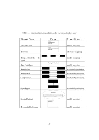
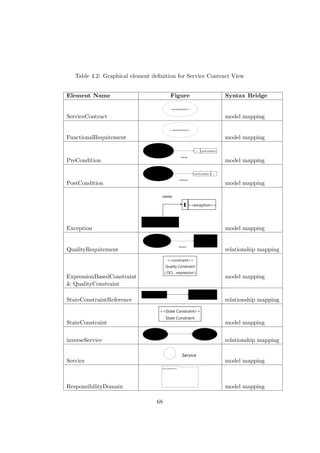
![Chapter 5
Tooling Evaluation
5.1 The Eclipse Modelling Project (EMP)
EMP is a collection of projects formed to
. . . coordinate and focus model-driven software development
capabilities within Eclipse. [31]
At its core is EMF [31]. EMF provides abstract syntax development
capabilities [31] through Ecore. Ecore is EMF’s implementation of EMOF
which is an OMG standard for practising MDA [32, 31]. EMOF is a standard
for defining a modelling language that is capable of defining an abstract
syntax [74]. MDA relies on EMOF for its modelling capabilities [6]. Since
EMOF is an MDA standard any abstract syntax defined through Ecore is
afforded wider tool support. The EMP suite of projects largely supports
OMG standards. Since many of the projects conform to MDA specifications
it is possible to consume an abstract syntax described in Ecore. The URDAD
DSL is described in Ecore.
In order to define models that conform to an abstract syntax a corre-
sponding concrete syntax is required. A concrete syntax enables practition-
ers to work with instances of models. Concrete syntaxes can be defined in a
text or graphical notation. A concrete textual syntax has been defined for
the URDAD DSL [68], but it is regarded as too technical [68].
A concrete graphical syntax that will make it easy for practitioners to
use the DSL [31] therefore needs to be developed.
5.2 Concrete Graphical Syntax Generation Frame-
works Evaluated
The EMF provides us with a basis for modelling an abstract syntax [31].
EMF includes a built-in XMI-based concrete syntax which is employed in
69](https://image.slidesharecdn.com/1e64cc26-cc26-48de-bf94-dbb7eebda95f-170126105214/85/22024582-70-320.jpg)
![EMF is at the center, providing abstract syntax-development capabilities. EMF
Query, Validation, and Transformation complement the EMF core functionality,
as do Teneo and CDO for database persistence of model instances. Surrounding
the abstract syntax-development components are model-transformation tech-
nologies, both model-to-text (Java Emitter Templates [JET] and Xpand) and
model-to-model (QVT and ATL). Beyond those lie concrete syntax development:
GMF used for graphical representation and Textual Modeling Framework (TMF)
used for textual representation of models. Finally, a series of orbiting projects and
components represent models, capabilities, and research initiatives available from
the Modeling project.
emf
EMFT
M
ODEL TO MODEL
TE
X
TUAL MODELING FRAMEW
OR
K
QUERY:V
ALIDATION : TRA
NSACTION
MODEL TO TEXTGRAP
HICAL MODELING FRAM
E
W
ORK
MDDi
MoDisco
XSD
UMLX
UML2
VIATRA2
AMW
MOFScript
OCL
ATL
EODM
GEMS
AM3
Figure 1-1 Eclipse Modeling Project
Figure 5.1: The Eclipse Modelling Project (EMP)
chapter 6 to demonstrate the consistency of the concrete graphical syntax.
The Graphical Editing Framework (GEF) supports programming of graph-
ical editors [5] (see figures 5.1 and 5.2).
In EMP there are two main frameworks based on GEF and Draw2D,
GMF and Graphiti [11]. They are aimed at creating rich graphical editors.
5.2.1 Graphical Modelling Framework (GMF)
GMF provides us with the framework and runtime infrastructure [3] capable
of developing a concrete graphical syntax [31]. GMF supports the develop-
ment of a graphical notation. The framework then maps the notation to the
abstract syntax it was defined for [31]. It simplifies this mapping between an
EMF compliant model and the GEF components that produce a diagram.
In order to utilise GMF a working knowledge of GEF, Draw2D as well
as EMF is required. The availability of these interfaces adds greatly to the
flexibility of GMF, yet adds more complexity to its use [11].
GMF has been around since 2005 [11] and is considered a more mature
70](https://image.slidesharecdn.com/1e64cc26-cc26-48de-bf94-dbb7eebda95f-170126105214/85/22024582-71-320.jpg)
![Graphical Modelling
Framework (GMF)
or
Graphiti
Graphical Editing Framework
(GEF)
Eclipse Modelling Framework (EMF)
Eclipse Modelling Project (EMP)
Figure 5.2: The relationship between the various EMP frameworks
technology [59] among the options available for the development of diagram
editor based on an abstract syntax.
5.2.2 Graphiti
An alternative to using GMF in populating models is Graphiti. Contrary to
extending the GEF and Draw2D components as in GMF, Graphiti is strictly
centred around an Application Program Interface (API) [4]. It wraps GEF
and Draw2D, providing an API capable of interacting with these components
[11]. A user requires only working knowledge of Graphiti and EMF to build
an editor [4].
The API-centric [4] approach of Graphiti provides the benefit of a simpler
interface, which ensures that it is easier to work with. However, due to this
approach flexibility is sacrificed [11]. Augmented by the standardised Look
& Feel of the UI [4], Graphiti does not have the steep learning curve of GMF
[59]. This comes at the expense of fewer features [59].
5.2.3 Graphiti vs GMF
In a comparison between Graphiti and GMF in research conducted by Refs-
dal (2012), GMF emerged as the framework with the most features [59].
Even though the Graphiti interface is simpler, Refsdal (2012) found that no
framework exceeded the other with regard to usability [59]. Refsdal (2012)
argued that it is better to use GMF when you have a larger domain model,
due to the increased initial development time required on Graphiti [59]. The
feature richness of GMF surpasses that of Graphiti, as expected, as Graphiti
only started in 2010 and is still in the incubation phase [11, 59]. The dif-
ferences between Graphiti and GMF are summarised in tabular format (see
71](https://image.slidesharecdn.com/1e64cc26-cc26-48de-bf94-dbb7eebda95f-170126105214/85/22024582-72-320.jpg)
![table 5.1) for ease of comparison.
Table 5.1: Graphiti vs. GMF
Graphiti GMF
GEF/Draw2D API-centric ap-
proach
extends these
frameworks
Interface self-contained GEF-dependent
Architecture runtime-oriented generative
Flexibility less than GMF more than Graphiti
Complexity less than GMF more than Graphiti
Maturity incubation phase
(2005)
mature (2010)
Features less than GMF more than Graphiti
Look & Feel standardized, de-
fined by SAP
usability experts
simple, adaptable
in generated code
Refsdal (2012) highlights the lack of integration of OCL with Graphiti,
even though OCL is supported by both GMF and Graphiti [59]. The com-
parison between the two frameworks indicates that there is no clear advan-
tage to using either. There seems to be a trade-off when using any one of
the two and the decision has to be based on the needs of the project. The
reasons cited most often for opting to use GMF are its maturity and the
possibility of encountering limitations when using Graphiti [11].
GMF is employed in developing an editor for the concrete graphical
syntax due to the fact that the framework is well established and perceived
to be more stable. GMF is sufficient in providing the capabilities required
for this project.
5.3 Structure and Implementation of Concrete Graph-
ical Syntax
The GMF workflow requires a domain model, which in this case is the UR-
DAD DSL expressed in the Ecore format. GMF supports the Ecore format.
A generator model (.genmodel) is derived from the Ecore file. The .ecore file
describes the actual meta model whereas the .genmodel file provides infor-
mation on code generation. The information contained within the generator
model is capable of generating Model, Edit, Editor and Test code (see table
5.2) most of which is relied upon by the diagram editor.
All four generation options were executed in this project as required by
the subsequent components in the GMF workflow.
72](https://image.slidesharecdn.com/1e64cc26-cc26-48de-bf94-dbb7eebda95f-170126105214/85/22024582-73-320.jpg)
![Table 5.2: Information contained within the (.genmodel)
Model All the entities, packages and factories are con-
tained within Model, they are used to create in-
stances of the model [1]
Edit Providers to display a model in a UI are con-
tained within Edit [1]
Editor An example editor capable of creating and mod-
ifying instances of a model [1]
Test Templates to write tests for a model are con-
tained within Test [1]
The GMF tooling component is created using the GMF project type.
The Ecore URDAD DSL is referenced and, as stated above, the supporting
code is generated from the (.genmodel).
In order to generate a diagram plug-in capable of supporting a concrete
graphical syntax, GMF employs transformations from a generator model
(.gmfgen) into a diagram plug-in. The components required for the trans-
formation of a generator model (.gmfgen) are:
• a graphical definition model (.gmfgraph),
• a tooling definition model (.gmftool), and
• a mapping model (.gmfmap).
Create GMF Project
Develop
Mapping Model
Adjust Generation
Parameters
Package and Deploy
Graphical Definition
Domain Model
Tooling Definition
M M
M T
«X»
Figure 5.3: The GMF workflow
The graphical definition model seen in figure 5.4 defines the figures used
to represent domain model elements on the diagram. The figures for the
73](https://image.slidesharecdn.com/1e64cc26-cc26-48de-bf94-dbb7eebda95f-170126105214/85/22024582-74-320.jpg)
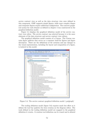
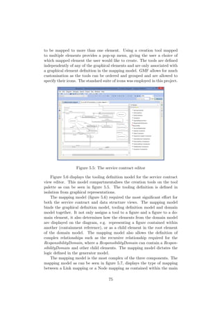
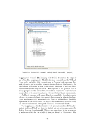
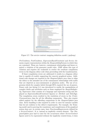
![not render the model invalid.
1 package urdad.diagram.parsers;
2
3 import org.eclipse.core.runtime.IStatus;
4 import org.eclipse.core.runtime.Status;
5 import org.eclipse.emf.ecore.EObject;
6
7 import urdad.data.impl.AttributeImpl;
8 import urdad.data.impl.RangeMultiplicityImpl;
9
10 public class ParserImpl {
11
12 public IStatus updateRangeValues(EObject target, String newString){
13 String[] parts = newString.replace("[", "").replace("]", "").split("..");
14 if (parts.length != 2 || parts[0].trim().length() == 0 || parts[1].trim().length() == 0) {
15 return Status.CANCEL_STATUS;
16 }
17
18 RangeMultiplicityImpl range = (RangeMultiplicityImpl)target.eContents().get(0);
19
20 if(range == null)
21 return Status.CANCEL_STATUS;
22
23 range.setMinOccurs(Integer.parseInt(parts[0]));
24 range.setMaxOccurs(Integer.parseInt(parts[1]));
25
26 return Status.OK_STATUS;}
27
28 public IStatus updateAttributeValues(EObject target, String newString){
29 String[] parts = newString.split(":");
30 if (parts[0].trim().length() == 0) {
31 return Status.CANCEL_STATUS;
32 }
33
34 AttributeImpl attribute = (AttributeImpl)target;
35
36 if(attribute == null)
37 return Status.CANCEL_STATUS;
38
39 attribute.setName(parts[0].trim());
40
41 return Status.OK_STATUS;}
42 }
Listing 5.1: The ParserImpl.java class for manipulating complex labels
defined in OCL (particularly an Expression)
1 /**
2 * @generated NOT
3 */
4 private IStatus updateValues(EObject target, String newString) throws ExecutionException {
5 ParserImpl parser = new ParserImpl();
6 return parser.updateRangeValues(target, newString);
7 }
Listing 5.2: Implementation of the parser in the expression label
The DiagramUpdater.java class is especially prominent in that it de-
termines the locations of figures on the diagram. Development is required
in this class in order to represent a figure with a containment reference to
another as a non-contained figure. For example, when a Postcondition is
dragged onto the diagram canvas the element needs to be defined within
the ResponsibilityDomain it was dropped in. Once it is linked to a Func-
tionalRequirements element, it needs to update the model to reflect that
the Postcondition resides within the related FunctionalRequirements. The
diagram, however, represents the Postcondition as an independent figure -
unbound to any other. The Postcondition, however, still needs to be con-
tained within the same ResponsibilityDomain as the FunctionalRequirements
that references it.
78](https://image.slidesharecdn.com/1e64cc26-cc26-48de-bf94-dbb7eebda95f-170126105214/85/22024582-79-320.jpg)

![Chapter 6
Graphical Syntax Evaluation
and Implementation
6.1 Graphical Syntax Evaluation
The graphical syntax developed in this project should be ontologically com-
plete to serve as an alternative to the textual syntax. The syntax should
cover at least the same elements of the meta model as those covered by the
textual syntax. Completeness of the syntax is ensured through the definition
and mapping of the syntax in chapter 4. The purpose of this chapter is to
demonstrate that the syntax is semiotically clear1 [47].
Tooling has been developed that is capable of supporting the graphical
syntax. These tools are used to demonstrate the viability and adequacy
of the syntax. The tooling leverages off GMF to depict an URDAD PIM
previously populated via a concrete textual syntax.
6.1.1 Principle of Semiotic Clarity
The graphical syntax ensures that there is a 1:1 mapping between all the
constructs required to display the elements pertinent to each view. An
exception is made with the functional requirements element which does not
have a notation. This is deliberately done to ensure that the principles of
complexity management [47] as well as graphic economy [47] are adhered to.
Therefore, the argument is made that this principle is adhered to as much
as is possible.
6.1.2 Principle of Perceptual Discriminability
A range of symbols has been employed to sufficiently distinguish all the sym-
bols and types from each other. Visual distance [47] is improved through
1
see 3.5.1
80](https://image.slidesharecdn.com/1e64cc26-cc26-48de-bf94-dbb7eebda95f-170126105214/85/22024582-81-320.jpg)
![Table 6.1: Graphical syntax evaluated against the 10 design principles
Principle Description Adherence
Semiotic clarity [47] There should be a 1:1 corre-
spondence between semantic
constructs and graphical sym-
bols
Adheres closely
Perceptual discrim-
inability [47]
Different symbols should be
clearly distinguishable from
each other
Adheres loosely
Semantic trans-
parency [47]
Use visual representations
whose appearance suggests
their meaning
Adheres loosely
Complexity manage-
ment [47]
Include explicit mechanisms
for dealing with complexity
Adheres closely
Cognitive integra-
tion [47]
Include explicit mechanisms
to support integration of in-
formation from different dia-
grams
Adheres loosely
Visual expressive-
ness [47]
Use the full range and capaci-
ties of visual variables
Adheres loosely
Dual coding [47] Use text to complement
graphics
Adheres closely
Graphic economy
[47]
The number of different
graphical symbols should be
cognitively manageable
Adheres closely
Cognitive fit [47] Use different visual dialects
for different tasks and audi-
ences
Adheres loosely
Interactions among
principles [47]
Interaction between principles Adheres closely
the use of the visual expressiveness [47] principle. The connector figures for
the association, inverse service and exception relations are similar, as are the
connector figures of quality requirements, and precondition and postcondi-
tion relations. They therefore do not adhere to this principle fully. The
location relation [34], as well as the dual coding [47] principle, is employed,
however, and they ensure that connectors are perceptually discriminable
[47].
81](https://image.slidesharecdn.com/1e64cc26-cc26-48de-bf94-dbb7eebda95f-170126105214/85/22024582-82-320.jpg)
![6.1.3 Principle of Semantic Transparency
Symbols that have previous meanings associated with them were preserved,
for example, in the case of data structure the meaning of, and manner in
which attribute is portrayed are in line with the UML Specification v2.4.1
[72]. For many of the elements new graphical representations have been de-
fined that are capable of clearly conveying the meaning. In the specific case
of a precondition and postcondition the pre-existing notation is discarded
for a newly defined notation, as the former does not promote the principle of
perceptual discriminability [47]. Iconic representations [47] further improve
the speed of recognition and recall, thus improving intelligibility. The new
notation definitions mean that this principle is not adhered to as closely as
would otherwise be possible.
6.1.4 Principle of Complexity Management
The elements that the respective views are comprised of have been limited
to those required to meaningfully represent a view. The symbols required
to represent various elements have been combined in the case of the service
contract and the functional requirements elements, as well as expression
based constraint and the expression elements. No non-value adding figures
or symbols were employed just for the sake of making the diagram more aes-
thetically pleasing (which promotes graphic economy [47]). The functional
nature of the primary notation is promoted to the fullest. The notation is
divided into its respective views, thus employing modularisation to manage
complexity. Another mechanism for managing complexity is hierarchy. It is
employed in representing the data structure view as well as the service con-
tract view when the the request and result data structures are represented
(see figure 6.4) and also applies to responsibility domains. This principle is
as closely adhered to as possible.
6.1.5 Principle of Cognitive Integration
The cognitive integration [47] mechanism, namely conceptual integration
[47], comes into play in representing the data structure view and service
contract view. The views are conceptually separated and represent different
layers of the same elements. The request and result data structures are
represented on both views. Between the service contract view and the data
structure view the same model is depicted and the relationship between
these views is clearly exposed. The use of the same notation for a data
structure that is used for a class in UML also promotes the principle of
cognitive integration [47]. The mechanism of perceptual integration [47] is,
however, neglected and thus this principle is only partially adhered to.
82](https://image.slidesharecdn.com/1e64cc26-cc26-48de-bf94-dbb7eebda95f-170126105214/85/22024582-83-320.jpg)
![6.1.6 Principle of Visual Expressiveness
The visual variables leveraged in order to promote visual expressiveness
are implicit in defining the notation. The use of colour is not explicitly
employed, yet the arrow symbol for the precondition and postcondition as
well as the service notation is a shade of grey. This contributes to adhering
to the perceptual discriminability [47] principle. Position is employed in the
symbol of the precondition and postcondition to convey some dissimilarity,
which enables differentiation between the figures. Shape is exhaustively
employed to promote perceptual discriminability [47].
6.1.7 Principle of Dual Coding
The principle of dual coding [47] is employed excessively to convey meaning
which contributes to the semiotic clarity [47] principle. This is especially ev-
ident in the connector relation figures. The text labels are used to promote
the principle of perceptual discriminability [47]. The most prominent use of
dual coding [47] is evident in the exception figure with a letter incorporated
in the figure. In most of the figures the name as well as a descriptive label
is employed alongside the figure’s shape to convey meaning and distinguish
between notations. Text is the only representation employed with the at-
tribute element, which promotes semantic transparency [47] and ultimately
the principle of complexity management [47].
6.1.8 Principle of Graphic Economy
Adherence to the principle of semiotic clarity [47] prescribes that the number
of graphical symbols should match the number of elements that need to be
represented. However, in certain cases elements were combined (introduc-
ing symbol deficit), which reduces the number of notations required. This
was done to promote visual expressiveness [47] and ensure that the principle
of graphic economy [47] is adhered to. This principle is complemented by
the complexity management [47] principle. The minimalistic nature of the
notation is evident in the service contract and precondition and postcon-
dition figures. Therefore, the principle of graphic economy [47] is adhered
to as much as is possible, taking into account the balance that has to be
maintained between principles.
6.1.9 Principle of Cognitive Fit
The most important principles that measure cognitive fit include perceptual
discriminability [47], semantic transparency [47] and visual expressiveness
[47]. They are not very closely adhered to in the definition of the notation,
and as a result the cognitive fit is reduced. However, the use of iconic
representations [47] in precondition and postcondition, is a step towards
83](https://image.slidesharecdn.com/1e64cc26-cc26-48de-bf94-dbb7eebda95f-170126105214/85/22024582-84-320.jpg)
![improving the cognitive effectiveness for the novice user. With regard
to the applicability of the notation to the task at hand, the cognitive fit is
increased due to the fact that the notation is designed especially for this
purpose.
6.1.10 Interactions among Principles
The effect of interactions among principles is most evident in the inter-
play between the semiotic clarity [47] and graphic economy [47] principles.
Graphic economy [47] aims to limit the clutter of the graphical representa-
tion to minimise the cognitive load for the user, whereas semiotic clarity [47]
demands a 1:1 mapping between constructs and graphical notation in order
to preserve the underlying meaning. The balance is, however, maintained
by combining related elements where applicable, i.e. grouping elements that
have to occur together to have meaning in this context. For example, the
expression based constraint and expression elements are combined into one
notation.
Balancing the principles and maintaining the interplay between them
have proved challenging. The salient properties of each principle are em-
ployed where they have the most impact in defining a notation capable of
achieving the design goal of cognitive effectiveness.
6.2 IEEE/ISO 42010-2011 Compliance
In order for an Architectural Description (AD) to comply with the IEEE/ISO
42010-2011 specification it must:
• contain the identification of stakeholders and concerns of the system-
of-interest,
• provide viewpoints and their definitions,
• contain views that conform to a viewpoint,
• declare any inconsistencies, and
• provide a rationale for the architecture [10].
The data structure specification and service contract specification con-
cerns are addressed in this project. These concerns stem from URDAD and
were identified for stakeholders that have an interest in the fulfilment of a
service [68]. The URDAD meta model caters for the identification of these
stakeholders and this project defines the viewpoints that are leveraged in
order to produce the views capable of addressing concerns of stakeholders.
The URDAD meta model is derived from the MOF/EMOF meta model
which ensures that any inconsistencies are exposed [68]. The specification
84](https://image.slidesharecdn.com/1e64cc26-cc26-48de-bf94-dbb7eebda95f-170126105214/85/22024582-85-320.jpg)
![also requires a rationale for the architecture [10]. In URDAD rationale links
for design decisions exist and are enforced by its meta model in the form of
requiredBy links between requirements and stakeholders [68].
The IEEE/ISO 42010-2011 specification also has certain requirements
for viewpoints. It requires that the data structure and service contract
viewpoints specify:
• one or more concerns that a viewpoint frames,
• stakeholders that have these concerns that are addressed by the view-
point,
• one or more model kinds that a viewpoint supports,
• the criteria for models of each model kind, and
• references to its source requirements [10].
The IEEE/ISO 42010-2011 specification states that a viewpoint frames
one or more concerns [10]. In this project each concern is framed by its
own viewpoint. The URDAD meta model caters for the specification of
stakeholders in line with IEEE/ISO 42010-2011 AD requirements.
The model, as per the viewpoint requirement, is an URDAD PIM that
the data structure and service contract viewpoints support. The IEEE/ISO
42010-2011 specification states that the fourth requirement can be met with
a meta model specifying the structure and conventions for models of a model
kind [10]. In this project this requirement is addressed by the URDAD meta
model that governs the construction of an URDAD PIM. This project defines
a concrete graphical syntax for views that are mapped to models that comply
with the URDAD DSL.
Another core requirement of the standard is traceability of any architec-
tural decisions back to requirements [10]. URDAD facilitates traceability in
that it requires each functional requirement to identify a service capable of
addressing it [69]. This ensures adherence to the linkage and consistency
requirements of the IEEE/ISO 42010-2011 specification.
6.3 Generating Views with the Concrete Graphi-
cal Syntax
In order to demonstrate the application of the graphical syntax to a non-
trivial example, a service contract view as well as a data structure view is
generated for the Enrollments responsibility domain.
The example has been employed previously to demonstrate the concrete
textual syntax defined by Solms, et al. (2011) [68].
The Enrollments responsibility domain does not properly demonstrate
the data structure view. However, the data structure view is demonstrated
85](https://image.slidesharecdn.com/1e64cc26-cc26-48de-bf94-dbb7eebda95f-170126105214/85/22024582-86-320.jpg)
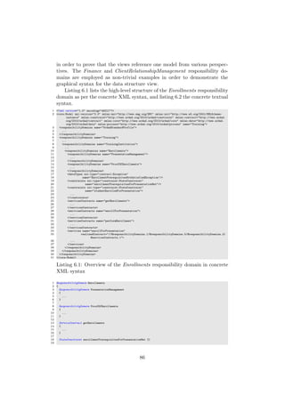
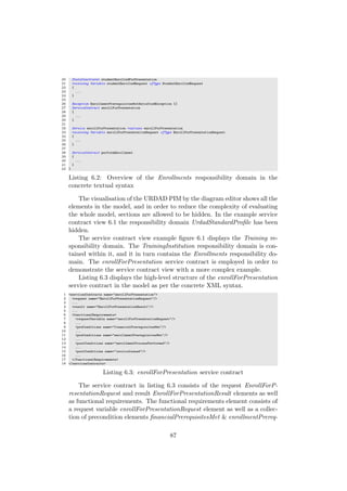
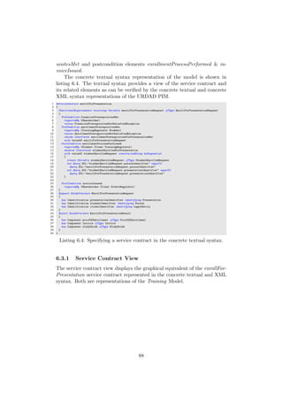
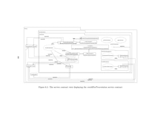
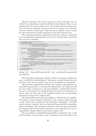
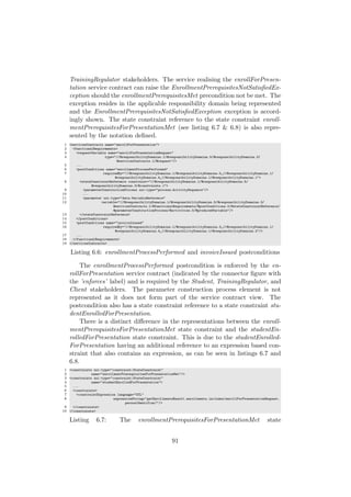
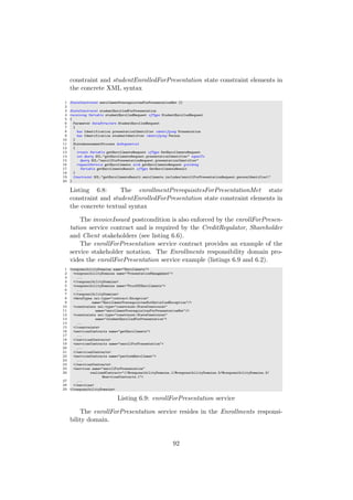
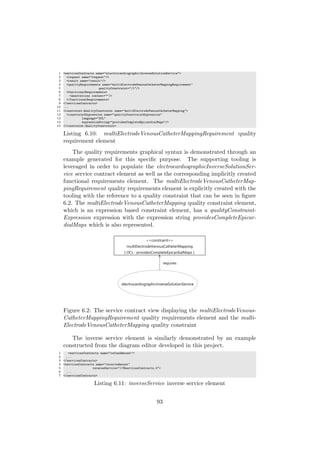
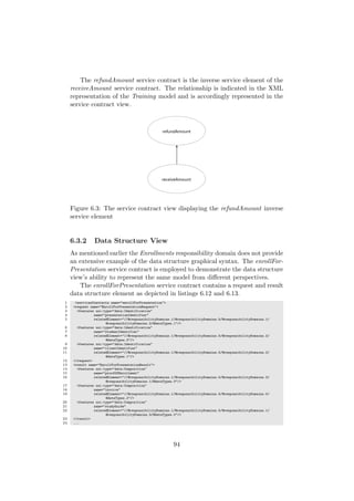
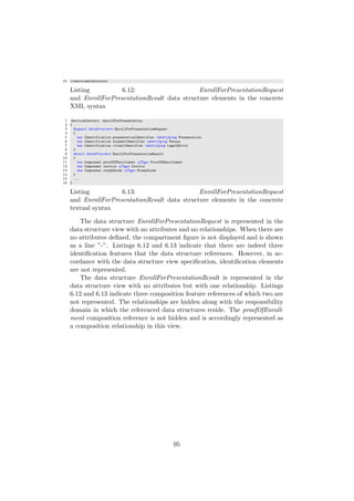
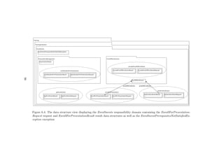
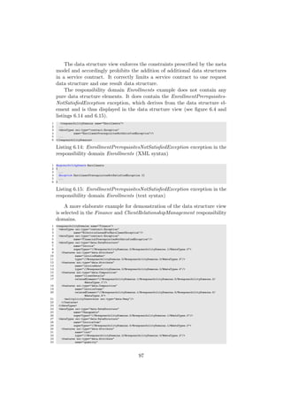
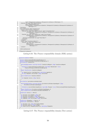
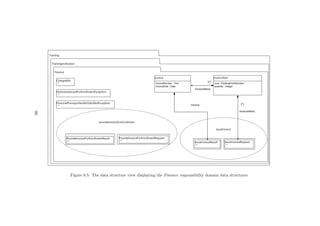
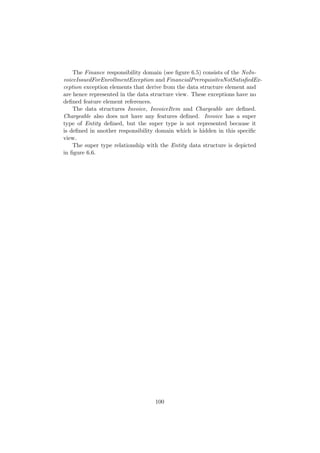
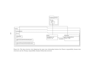
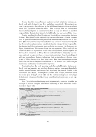
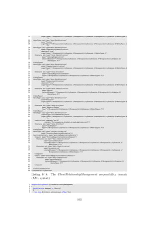
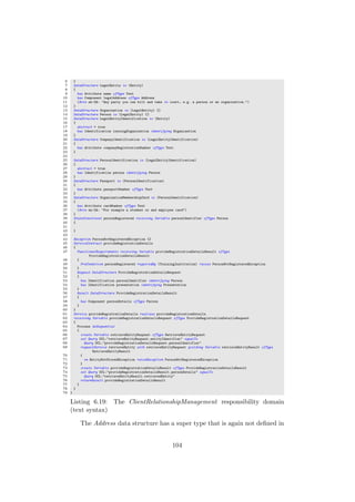

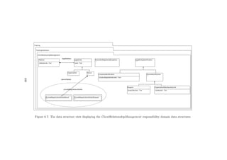
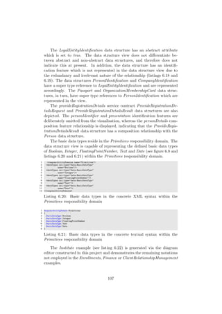
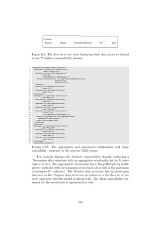
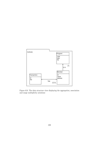
![archy. Figures mapped to elements needed to be severely constrained in
order to be represented by the diagram editor. The association, aggrega-
tion and composition elements required some severe OCL constrains for the
diagram editor to sufficiently differentiate between them for their represen-
tation. The structure and semantics of a DSL can be refined using OCL
[31]. In addition, the service contract attributes, request and result, require
a compartment mapping for the framework to differentiate between them.
They cannot be differentiated according to Type in an OCL constraint as
they are identically typed.
One of the guiding principles of creating the tooling was to alter the
generated code as little as possible. Any code altered runs the risk of being
overwritten when it is regenerated. The framework supports the preserva-
tion of altered code in the form of an ’@Generated NOT’ method annotation.
This is, however, cumbersome and unsafe. Annotating the code does not
cater for the corruption of regenerated code. This occurred often, due to
the changes required in the GMF mapping model. Corrupted editor code
requires deletion and regeneration, resulting in the loss of all altered code,
annotated or not. The corruption of the Eclipse development environment
also contributed to minimise the use of altered code and ensure the GMF
framework implementation was as vanilla as possible.
Altered code was unavoidable and crucial changes were required when
implementing containment references as non-containment relationships (e.g.
the expression based constraint, precondition and postcondition elements)
as well as allowing the alteration of OCL defined expression Labels (e.g.
attributes with data types and range multiplicity). The non-standard way
in which containment references were depicted as relationships also required
significant changes to align the diagram editor and meta model.
The usability, flexibility and instability properties of the GMF framework
places a high premium on the GMF learning curve.
7.2 Tooling Enhancements
7.2.1 Filtering
The diagram editor supports filtering in a standard manner as provided by
GMF. The ability to hide and show certain figures on a diagram allows for
the creation of views from viewpoints that target a specific concern. The
editor shows all figures by default and then allows the practitioner to hide
figures as needed. This is a labour intensive process which requires intense
concentration. It is also a repetitive task that has to be undertaken for each
view that is constructed from the same model. Once a figure is hidden there
is no way of selecting only that figure to be shown again. All figures need
to be shown and those not applicable to the view need to be hidden again.
111](https://image.slidesharecdn.com/1e64cc26-cc26-48de-bf94-dbb7eebda95f-170126105214/85/22024582-112-320.jpg)
![7.2.2 Layout
In certain cases the figures and their containment have a free-form type lay-
out, as in the responsibility domain figure. In cases where a more structured
layout is required, compartments are employed, such as in the case of the
service contract notation in the data structure view.
Layout contributes to the visual expressiveness of the notation. The
diagram editor developed for this project does support the manual layout of
a diagram, yet with larger diagrams it is a monotonous and labour intensive
task. GMF provides a built-in automatic layout function. It does not,
however, sufficiently lay out the figures into an intuitive style and detracts
from the visual expressiveness of the notation [47].
7.2.3 Abstract Notation Implementation
Data structures have an abstract attribute that is represented as a prop-
erty in the diagram editor. The property indicates ’true’ or ’false’, which
meets the minimum requirement for representing this attribute. The UML
Specification v2.4.1 [72], however, specifies the class figure with the name in
italics as the prescribed manner of depicting a figure as abstract [72]. The
cognitive effectiveness of the visual representations as well as the use of the
diagram editor would be enhanced by the application of this convention.
7.3 URDAD Meta Model Improvements
The identification element in the URDAD meta model resulted from UML
not differentiating between identification (being purely able to identify an
object) and association (being able to navigate to the object and query its
members or request services from it). If one object has an identification link
to another object, then it stores a unique identifier (e.g. URI, key, . . . ) for
that other object, but may not have an access path (e.g. a URL, a pointer,
. . . ) to it. The identification element, however, does not seem to add any
value to the URDAD meta model and could possibly be excluded from the
URDAD DSL.
7.3.1 URDAD Meta Model Constraints
The URDAD meta model is not constrained at this stage. The lack of
constraints allows too much freedom in populating a model that subscribes
to the URDAD meta model. The supporting tooling inherits constraints
from its corresponding meta model, and exposes certain fallacies and critical
constraints in populating an URDAD PIM.
Improvements that can be brought about by constraining the meta model
are listed below.
112](https://image.slidesharecdn.com/1e64cc26-cc26-48de-bf94-dbb7eebda95f-170126105214/85/22024582-113-320.jpg)

![Bibliography
[1] EMF tutorial EclipseSource blog. http://eclipsesource.com/
blogs/tutorials/emf-tutorial/. Accessed: 2013-11-04.
[2] Frequently asked questions on W3C’s web ontology language (OWL).
http://www.w3.org/2003/08/owlfaq. Accessed: 2013-11-04.
[3] Graphical modeling framework. http://www.eclipse.org/modeling/
gmp/. Accessed: 2013-11-04.
[4] Graphiti - overview. http://www.eclipse.org/graphiti/
documentation/overview.php. Accessed: 2013-11-04.
[5] Help - eclipse platform. http://help.eclipse.org/juno/index.jsp.
Accessed: 2013-11-04.
[6] OMG’s MetaObject facility (MOF) home page. http://www.omg.org/
mof/. Accessed: 2013-11-04.
[7] Platform-independent model for service-oriented architecture
(PIM4SOA). http://pim4soa.sourceforge.net/. Accessed:
2013-11-04.
[8] SRML a service modelling language. http://www.cs.le.ac.uk/srml/
#section-1. Accessed: 2013-11-04.
[9] IEEE std 1175.1-2002: Ieee guide for case tool interconnections - clas-
sification and description. Specification, IEEE-SA Standards Board,
2003.
[10] IEEE std 42010-2011: Systems and software engineering – architecture
description. Specification, IEEE-SA Standards Board, December 2011.
[11] Koen Aers. Graphiti and gmf compared: Revisiting the graph editor.
In EclipseCon 2011, Santa Clara, California, March 2011.
[12] Aditya Agrawal, Gabor Karsai, and ´Akos L´edeczi. An end-to-end
domain-driven software development framework. In Companion of the
18th annual ACM SIGPLAN conference on Object-oriented program-
ming, systems, languages, and applications, pages 8–15. ACM, 2003.
115](https://image.slidesharecdn.com/1e64cc26-cc26-48de-bf94-dbb7eebda95f-170126105214/85/22024582-116-320.jpg)
![[13] David Akehurst and Octavian Patrascoiu. Ocl 2.0-implementing the
standard for multiple metamodels. Electr. Notes Theor. Comput. Sci,
102:21–41, 2004.
[14] Perry Alexander. Best of both worlds [formal and semi-formal software
engineering]. Potentials, IEEE, 14(5):29–32, 1995.
[15] Albert Ambroziewicz and Michal ´Smialek. Application logic patterns–
reusable elements of user-system interaction. In Model Driven Engi-
neering Languages and Systems, pages 241–255. Springer, 2010.
[16] Arne Jorgen Berre. Service oriented architecture modeling language
(soaml)-specification for the uml profile and metamodel for services
(upms). Object Management Group (OMG), 2008.
[17] Jacques Bertin. Semiology of graphics: diagrams, networks, maps.
1983.
[18] Rafael Magalhaes Borges and Alexandre Cabral Mota. Integrating uml
and formal methods. Electronic Notes in Theoretical Computer Science,
184:97–112, 2007.
[19] Steen Brahe and Tonny Madsen. Model driven software development.
principles, standards, and techniques. 2010.
[20] Edmund Melson Clarke and Jeannette M. Wing. Formal methods: state
of the art and future directions. ACM Comput. Surv., 28(4):626–643,
December 1996.
[21] J.C. Corbett, M.B. Dwyer, J. Hatcliff, S. Laubach, C.S. Pasareanu,
Robby, and Hongjun Zheng. Bandera: extracting finite-state models
from java source code. In Software Engineering, 2000. Proceedings of
the 2000 International Conference on, pages 439 –448, 2000.
[22] Stephen Cranefield and Jin Pan. Bridging the gap between the model-
driven architecture and ontology engineering. International Journal of
Human-Computer Studies, 65(7):595–609, 2007.
[23] Andrea Delgado, Francisco Ruiz, Ignacio Garcia-Rodriguez de Guzman,
and Mario Piattini. A model-driven and service-oriented framework
for the business process improvement. Journal of Systems Integration,
1(3):45–56, 2010.
[24] R. D’ilppolito. Using models in software engineering. In Proceedings of
the conference on Tri-Ada’89: Ada technology in context: application,
development, and deployment, pages 256–265. ACM, 1989.
[25] Craig Edwards. Transformation of an URDAD Platform Independent
Model into a Java EE EJB Model. University of Pretoria, 2011.
116](https://image.slidesharecdn.com/1e64cc26-cc26-48de-bf94-dbb7eebda95f-170126105214/85/22024582-117-320.jpg)
![[26] Agung Fatwanto and Clive Boughton. Architectural description for
translative model-driven development. In Knowledge Acquisition and
Modeling, 2008. KAM ’08. International Symposium on, pages 619 –
623, dec. 2008.
[27] Torsten Fink, Manuel Koch, and Karl Pauls. An mda approach to access
control specifications using mof and uml profiles. Electronic Notes in
Theoretical Computer Science, 142:161–179, 2006.
[28] Andreas Gehlert and Werner Esswein. Toward a formal research
framework for ontological analyses. Advanced Engineering Informatics,
21(2):119 – 131, 2007. Ontology of Systems and Software Engineering;
Techniques to Support Collaborative Engineering Environments.
[29] Tom Gilb and Susannah Finzi. Principles of software engineering man-
agement, volume 4. Addison-Wesley Reading, MA, 1988.
[30] L´eszlo G¨onczy. Methodology for a precise development process of ser-
vice oriented applications. n Leicester, page 50, 2007.
[31] R.C. Gronback. Eclipse Modeling Project: A Domain-Specific Language
Toolkit. The Eclipse Series. Addison-Wesley, 2009.
[32] Richard C. Gronback and Ed Merks. Model driven architecture
at eclipse. The European Journal for the Informatics Professional,
2008(2), April 2008.
[33] Anthony Hall and David Isaac. Formal methods in a real air traffic con-
trol project. In Software in Air Traffic Control Systems - The Future,
IEE Colloquium on, pages 7/1–7/4, 1992.
[34] Xiao He, Zhiyi Ma, Weizhong Shao, and Ge Li. A metamodel for the
notation of graphical modeling languages. In Computer Software and
Applications Conference, 2007. COMPSAC 2007. 31st Annual Inter-
national, volume 1, pages 219–224. IEEE, 2007.
[35] Florian Heidenreich, Jendrik Johannes, Sven Karol, Mirko Seifert, and
Christian Wende. Derivation and refinement of textual syntax for mod-
els. In Model Driven Architecture-Foundations and Applications, pages
114–129. Springer, 2009.
[36] Harri Karhunen. Dynamic method for service-oriented software design.
In Proc. 28th Information Systems Research Seminar in Scandinavia,
Kristiansand, Norway, 2005.
[37] Ralf Kneuper. Limits of formal methods. Formal Aspects of Computing,
9(4):379–394, 1997.
117](https://image.slidesharecdn.com/1e64cc26-cc26-48de-bf94-dbb7eebda95f-170126105214/85/22024582-118-320.jpg)
![[38] Stephen M. Kosslyn. Graphics and human information processing: A
review of five books. Journal of the American Statistical Association,
80(391):pp. 499–512, 1985.
[39] Jill H. Larkin and Herbert A. Simon. Why a diagram is (sometimes)
worth ten thousand words. Cognitive Science, 11(1):65 – 100, 1987.
[40] Susanne Leist and Gregor Zellner. Evaluation of current architecture
frameworks. In Proceedings of the 2006 ACM symposium on Applied
computing, pages 1546–1553. ACM, 2006.
[41] Zhiyi Ma, Xiao He, and Lianghuan Kang. A model driven develop-
ment platform for service-oriented applications. In Services-II, 2009.
SERVICES-2’09. World Conference on, pages 17–24. IEEE, 2009.
[42] Mark Maier and Eberhardt Rechtin. The art of systems architecting.
CRC PressI Llc, 2000.
[43] Joaquin Miller, Jishnu Mukerji, et al. Mda guide version 1.0. 1. Object
Management Group, 234:51, 2003.
[44] Rob Miller. Graphic design. ui design and implementation. 2004.
[45] Parastoo Mohagheghi and Jan Aagedal. Evaluating quality in model-
driven engineering. In Proceedings of the International Workshop on
Modeling in Software Engineering, MISE ’07, pages 6–, Washington,
DC, USA, 2007. IEEE Computer Society.
[46] Jean Fran¸cois Monin and Michael Gerard Hinchey. Understanding for-
mal methods. Springer, 2003.
[47] Daniel L. Moody. The ’physics’ of notations: Toward a scientific ba-
sis for constructing visual notations in software engineering. Software
Engineering, IEEE Transactions on, 35(6):756 –779, nov.-dec. 2009.
[48] Daniel L. Moody, Patrick Heymans, and Raimundas Matulevicius. Vi-
sual syntax does matter: improving the cognitive effectiveness of the i*
visual notation. Requirements Engineering, 15:141–175, 2010.
[49] Sedighe Moosavi, Mir Ali Seyyedi, and Nasrollah Moghadam. A method
for service oriented design. In Information Technology: New Genera-
tions, 2009. ITNG’09. Sixth International Conference on, pages 290–
295. IEEE, 2009.
[50] Liping Mu, Terje Gjøsæter, Andreas Prinz, and Merete Skjelten Tveit.
Specification of modelling languages in a flexible meta-model architec-
ture. In Proceedings of the Fourth European Conference on Software
Architecture: Companion Volume, pages 302–308. ACM, 2010.
118](https://image.slidesharecdn.com/1e64cc26-cc26-48de-bf94-dbb7eebda95f-170126105214/85/22024582-119-320.jpg)
![[51] Pierre-Alain Muller, Fr´ed´eric Fondement, Franck Fleurey, Michel Has-
senforder, R´emi Schnekenburger, S´ebastien G´erard, and Jean-Marc
J´ez´equel. Model-driven analysis and synthesis of textual concrete syn-
tax. Software & Systems Modeling, 7(4):423–441, 2008.
[52] Allan Paivio. Mental representations: A dual coding approach. Num-
ber 9. Oxford University Press, USA, 1990.
[53] Allan Paivio. Dual coding theory. Educating the other America, pages
227–242, 2008.
[54] Marian Petre. Why looking isn’t always seeing: readership skills and
graphical programming. Commun. ACM, 38(6):33–44, June 1995.
[55] Claudia Pons and Diego Garcia. A lightweight approach for the seman-
tic validation of model refinements. Electronic Notes in Theoretical
Computer Science, 220(1):43–61, 2008.
[56] Dick Quartel, Remco Dijkman, and Marten van Sinderen. Method-
ological support for service-oriented design with isdl. In Proceedings of
the 2nd international conference on Service oriented computing, pages
1–10. ACM, 2004.
[57] Ervin Ramollari, Dimitris Dranidis, and Anthony JH Simons. A survey
of service oriented development methodologies. In The 2nd European
Young Researchers Workshop on Service Oriented Computing, page 75,
2007.
[58] Daniel Ratiu, Bernhard Schaetz, Markus Voelter, and Bernd Kolb. Lan-
guage engineering as an enabler for incrementally defined formal anal-
yses. In Software Engineering: Rigorous and Agile Approaches (Form-
SERA), 2012 Formal Methods in, pages 9–15. IEEE, 2012.
[59] Ivar Refsdal. Comparison of gmf and graphiti based on experiences
from the development of the prediqt tool. 2012.
[60] Hans Schippers, Pieter Van Gorp, and Dirk Janssens. Leveraging uml
profiles to generate plugins from visual model transformations. Elec-
tronic Notes in Theoretical Computer Science, 127(3):5–16, 2005.
[61] G. Michael Schneider, Johnny Martin, and W. T. Tsai. An experimental
study of fault detection in user requirements documents. ACM Trans.
Softw. Eng. Methodol., 1(2):188–204, April 1992.
[62] Bran Selic. The pragmatics of model-driven development. Software,
IEEE, 20(5):19–25, 2003.
119](https://image.slidesharecdn.com/1e64cc26-cc26-48de-bf94-dbb7eebda95f-170126105214/85/22024582-120-320.jpg)
![[63] Claude Elwood Shannon. A mathematical theory of communication.
ACM SIGMOBILE Mobile Computing and Communications Review,
5(1):3–55, 2001.
[64] Yashwant Singh and Manu Sood. Model driven architecture: A per-
spective. In Advance Computing Conference, 2009. IACC 2009. IEEE
International, pages 1644 –1652, march 2009.
[65] James Skene and Wolfgang Emmerich. Specifications, not meta-models.
In Proceedings of the 2006 international workshop on Global integrated
model management, pages 47–54. ACM, 2006.
[66] Richard Soley et al. Model driven architecture. OMG white paper,
308:308, 2000.
[67] Fritz Solms. What is software architecture? In Proceedings of the South
African Institute for Computer Scientists and Information Technolo-
gists Conference, SAICSIT ’12, pages 363–373, New York, NY, USA,
2012. ACM.
[68] Fritz Solms, Craig Edwards, Alexander Paar, and Stefan Gruner. A
domain-specific language for URDAD based requirements elicitation.
In Proceedings of the South African Institute of Computer Scientists
and Information Technologists Conference on Knowledge, Innovation
and Leadership in a Diverse, Multidisciplinary Environment, SAICSIT
’11, page 224230, New York, NY, USA, 2011. ACM.
[69] Fritz Solms, Stefan Gruner, and Cuen Edwards. Urdad as a quality-
driven analysis and design process. In SoMeT, pages 141–158, 2011.
[70] Fritz Solms and Dawid Loubser. Generating MDA’s platform indepen-
dent model using URDAD. Knowledge-Based Systems, 22(3):174–185,
April 2009.
[71] Fritz Solms and Dawid Loubser. URDAD as a semi-formal approach to
analysis and design. Innovations in Systems and Software Engineering,
6:155–162, 2010. 10.1007/s11334-009-0113-4.
[72] OMG Specification. Omg unified modeling language (omg uml), super-
structure, version 2.4.1. Object Management Group, 2011.
[73] Jonathan Sprinkle and Gabor Karsai. A domain-specific visual language
for domain model evolution. Journal of Visual Languages & Computing,
15(3):291–307, 2004.
[74] Steffen Staab, Tobias Walter, Gerd Gr¨oner, and Fernando Silva Par-
reiras. Model driven engineering with ontology technologies. In Reason-
ing Web. Semantic Technologies for Software Engineering, pages 62–98.
Springer, 2010.
120](https://image.slidesharecdn.com/1e64cc26-cc26-48de-bf94-dbb7eebda95f-170126105214/85/22024582-121-320.jpg)
![[75] Jihed Touzi, Fr´ederick Benaben, Herv´e Pingaud, and Jean Pierre Lorr´e.
A model-driven approach for collaborative service-oriented architecture
design. International journal of production economics, 121(1):5–20,
2009.
[76] MJ Wiering, MM Bonsangue, R Van Buuren, LPJ Groenewegen,
H Jonkers, and MM Lankhorst. Investigating the mapping of an enter-
prise description language into uml 2.0. Electronic Notes in Theoretical
Computer Science, 101:155–179, 2004.
[77] Jinhong Zhao, Shufen Liu, Xianyan Wang, Liang Chen, and Chuyi
Wei. Research and design of an executable modeling language based
on mof. In Computer-Aided Industrial Design and Conceptual Design,
2008. CAID/CD 2008. 9th International Conference on, pages 399–404.
IEEE, 2008.
[78] Michael Zhivich and Robert K. Cunningham. The real cost of software
errors. Security Privacy, IEEE, 7(2):87 –90, march-april 2009.
121](https://image.slidesharecdn.com/1e64cc26-cc26-48de-bf94-dbb7eebda95f-170126105214/85/22024582-122-320.jpg)