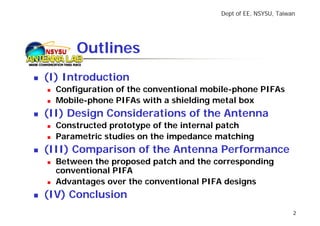
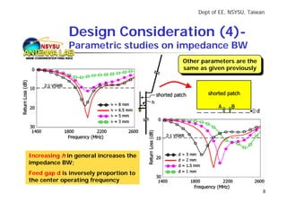
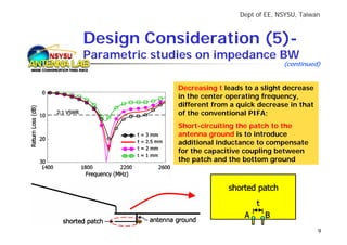
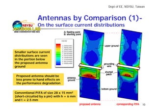
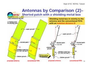
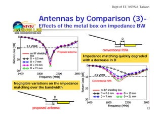
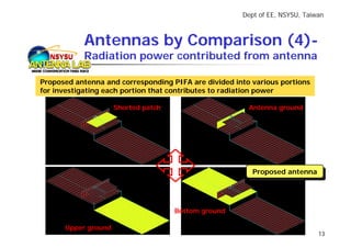
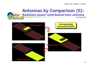
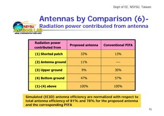
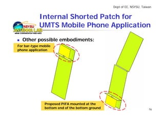
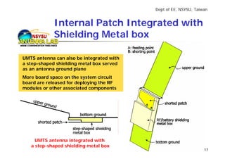
2005 IEEE AP-S
                                                  International Symposium


             Internal Shorted Patch Antenna
           NSYSU for UMTS Mobile Phone

*Saou-Wen Su1, Kin-Lu Wong1, C.L. Tang2, S.H. Yeh2
                  1
                   Dept. of Electrical Engineering
                  National Sun Yat-Sen University
                     Kaohsiung 80424, Taiwan
            2
             Computer & Communications Research Lab
              Industrial Technology Research Institute
                       Hsinchu 31040, Taiwan
                  *E-mail: susw@ema.ee.nsysu.edu.tw
Jul 2005
Dept of EE, NSYSU, Taiwan


NSYSU   Outlines
(I) Introduction
  Configuration of the conventional mobile-phone PIFAs
  Mobile-phone PIFAs with a shielding metal box
(II) Design Considerations of the Antenna
  Constructed prototype of the internal patch
  Parametric studies on the impedance matching
(III) Comparison of the Antenna Performance
  Between the proposed patch and the corresponding
  conventional PIFA
  Advantages over the conventional PIFA designs
(IV) Conclusion
                                                               2
Dept of EE, NSYSU, Taiwan


             Conventional PIFAs (1)-
    NSYSU    On the feeding/short-circuiting PIFAs

   Conventional PIFAs mainly comprise: a top patch,
   a feeding pin, and a shorting pin


The top patch is usually mounted above a system ground plane;
The shorting and feeding pins, connected to the top patch at proper positions,
have the same length as the distance between the patch and the ground plane
                                                                                 3
Dept of EE, NSYSU, Taiwan


                  Conventional PIFAs (2)-
       NSYSU      Metal box placed away from the PIFAs
                            Conventionally a large isolation distance (usually > 7 mm)
                            is required between the internal PIFA and the RF/battery
                            shielding box for avoiding destructive coupling


MOTL, vol. 32, pp. 87-88, Jan 2002                  MOTL, vol. 41, pp. 483-486, Jun 2004   4
Dept of EE, NSYSU, Taiwan


        Design Consideration (1)-
NSYSU   Configuration of the internal patch


                               Detailed dimensions of the
                               shorted patch;
                               Design example for UMTS
                               folder-type mobile phones


                                    TW/US Patent Pending    5
Dept of EE, NSYSU, Taiwan


               Design Consideration (2)-
    NSYSU      Antenna return-loss performance
                                  9.6-dB RL BW (2:1 VSWR)
                                  satisfies the UMTS band,
                                  1920~2170 MHz


                                              Relatively small variations in the
                                              measured RL for three possible
                                              talk positions are seen


The center frequency can be obtained
from the following equation:
                      c
          f≈
               4 × (0.5L + W )
where c is the speed of light
                                                                                   6
Dept of EE, NSYSU, Taiwan


              Design Consideration (3)-
     NSYSU    Measured radiation patterns, peak gain
                                              Measurement is for the
                                              Measurement is for the
                                            talk position with α = 15oo
                                             talk position with α = 15


Peak antenna gain level reaches about 3.4 dBi
across the UMTS band
                                                                                  7
Dept of EE, NSYSU, Taiwan


             Design Consideration (4)-
    NSYSU    Parametric studies on impedance BW
                                        Other parameters are the
                                        Other parameters are the
                                        same as given previously
                                         same as given previously


Increasing h in general increases the
impedance BW;
Feed gap d is inversely proportion to
the center operating frequency
                                                                     8
Dept of EE, NSYSU, Taiwan


        Design Consideration (5)-
NSYSU   Parametric studies on impedance BW
                                                    (continued)


                      Decreasing t leads to a slight decrease
                      in the center operating frequency,
                      different from a quick decrease in that
                      of the conventional PIFA;
                      Short-circuiting the patch to the
                      antenna ground is to introduce
                      additional inductance to compensate
                      for the capacitive coupling between
                      the patch and the bottom ground


                                                                9
Dept of EE, NSYSU, Taiwan


               Antennas by Comparison (1)-
     NSYSU     On the surface current distributions


Smaller surface current
distributions are seen
in the portion below
the proposed antenna
ground


 Proposed antenna should be
 less prone to hand effects on
 the performance degradation


Conventional PIFA of size 28 x 15 mm2
(short-circuited by a pin) with h = 6 mm
and t = 2.5 mm
                                                                   10
Dept of EE, NSYSU, Taiwan


        Antennas by Comparison (2)-
NSYSU   Shorted patch with a shielding metal box
                                 Shielding metal box in vicinity to the
                                 antenna and the conventional PIFA
                                 with an isolation distance D


                     Detailed
                      Detailed


                                                                       11
Dept of EE, NSYSU, Taiwan


              Antennas by Comparison (3)-
     NSYSU    Effects of the metal box on impedance BW


                                         Impedance matching quickly degraded
                                         with a decrease in D


Negligible variations on the impedance
matching over the bandwidth


                                                                               12
Dept of EE, NSYSU, Taiwan


           Antennas by Comparison (4)-
  NSYSU    Radiation power contributed from antenna

Proposed antenna and corresponding PIFA are divided into various portions
for investigating each portion that contributes to radiation power

                     Shorted patch                      Antenna ground


                                                         Proposed antenna
                                                          Proposed antenna


                                     Bottom ground

      Upper ground
                                                                             13
Dept of EE, NSYSU, Taiwan


        Antennas by Comparison (5)-
NSYSU   Radiation power contributed from antenna
                                                                 (continued)


                  Shorted patch
                                              Corresponding
                                               Corresponding
                                            conventional PIFA
                                             conventional PIFA


                                  Bottom ground


   Upper ground
                                                                          14
Dept of EE, NSYSU, Taiwan


         Antennas by Comparison (6)-
NSYSU    Radiation power contributed from antenna


 Simulated (IE3D) antenna efficiency are normalized with respect to
 total antenna efficiency of 81% and 78% for the proposed antenna
 and the corresponding PIFA
                                                                           15
Dept of EE, NSYSU, Taiwan


            Internal Shorted Patch for
   NSYSU    UMTS Mobile Phone Application
  Other possible embodiments:
For bar-type mobile
phone application


               Proposed PIFA mounted at the
               bottom end of the bottom ground                          16
Dept of EE, NSYSU, Taiwan


             Internal Patch Integrated with
   NSYSU     Shielding Metal box

UMTS antenna can also be integrated with
a step-shaped shielding metal box served
as an antenna ground plane
More board space on the system circuit
board are released for deploying the RF
modules or other associated components


     UMTS antenna integrated with
   a step-shaped shielding metal box
                                                                  17
Dept of EE, NSYSU, Taiwan


NSYSU   Conclusion

Proposed shorted patch antenna can be
arranged to be in close vicinity to the RF
shielding metal box with small coupling
effects between the antenna and the
shielding metal box
More designs of the internal mobile
antenna integrated with the shielding
metal box are foreseen and in progress

                                                      18
Dept of EE, NSYSU, Taiwan


THANK YOU FOR YOUR ATTENTION!
  NSYSU


                                            19

2005 IEEE AP-S-Internal Shorted Patch Antenna for UMTS Mobile Phone

  • 1.
    2005 IEEE AP-S International Symposium Internal Shorted Patch Antenna NSYSU for UMTS Mobile Phone *Saou-Wen Su1, Kin-Lu Wong1, C.L. Tang2, S.H. Yeh2 1 Dept. of Electrical Engineering National Sun Yat-Sen University Kaohsiung 80424, Taiwan 2 Computer & Communications Research Lab Industrial Technology Research Institute Hsinchu 31040, Taiwan *E-mail: susw@ema.ee.nsysu.edu.tw Jul 2005
  • 2.
    Dept of EE,NSYSU, Taiwan NSYSU Outlines (I) Introduction Configuration of the conventional mobile-phone PIFAs Mobile-phone PIFAs with a shielding metal box (II) Design Considerations of the Antenna Constructed prototype of the internal patch Parametric studies on the impedance matching (III) Comparison of the Antenna Performance Between the proposed patch and the corresponding conventional PIFA Advantages over the conventional PIFA designs (IV) Conclusion 2
  • 3.
    Dept of EE,NSYSU, Taiwan Conventional PIFAs (1)- NSYSU On the feeding/short-circuiting PIFAs Conventional PIFAs mainly comprise: a top patch, a feeding pin, and a shorting pin The top patch is usually mounted above a system ground plane; The shorting and feeding pins, connected to the top patch at proper positions, have the same length as the distance between the patch and the ground plane 3
  • 4.
    Dept of EE,NSYSU, Taiwan Conventional PIFAs (2)- NSYSU Metal box placed away from the PIFAs Conventionally a large isolation distance (usually > 7 mm) is required between the internal PIFA and the RF/battery shielding box for avoiding destructive coupling MOTL, vol. 32, pp. 87-88, Jan 2002 MOTL, vol. 41, pp. 483-486, Jun 2004 4
  • 5.
    Dept of EE,NSYSU, Taiwan Design Consideration (1)- NSYSU Configuration of the internal patch Detailed dimensions of the shorted patch; Design example for UMTS folder-type mobile phones TW/US Patent Pending 5
  • 6.
    Dept of EE,NSYSU, Taiwan Design Consideration (2)- NSYSU Antenna return-loss performance 9.6-dB RL BW (2:1 VSWR) satisfies the UMTS band, 1920~2170 MHz Relatively small variations in the measured RL for three possible talk positions are seen The center frequency can be obtained from the following equation: c f≈ 4 × (0.5L + W ) where c is the speed of light 6
  • 7.
    Dept of EE,NSYSU, Taiwan Design Consideration (3)- NSYSU Measured radiation patterns, peak gain Measurement is for the Measurement is for the talk position with α = 15oo talk position with α = 15 Peak antenna gain level reaches about 3.4 dBi across the UMTS band 7
  • 8.
    Dept of EE,NSYSU, Taiwan Design Consideration (4)- NSYSU Parametric studies on impedance BW Other parameters are the Other parameters are the same as given previously same as given previously Increasing h in general increases the impedance BW; Feed gap d is inversely proportion to the center operating frequency 8
  • 9.
    Dept of EE,NSYSU, Taiwan Design Consideration (5)- NSYSU Parametric studies on impedance BW (continued) Decreasing t leads to a slight decrease in the center operating frequency, different from a quick decrease in that of the conventional PIFA; Short-circuiting the patch to the antenna ground is to introduce additional inductance to compensate for the capacitive coupling between the patch and the bottom ground 9
  • 10.
    Dept of EE,NSYSU, Taiwan Antennas by Comparison (1)- NSYSU On the surface current distributions Smaller surface current distributions are seen in the portion below the proposed antenna ground Proposed antenna should be less prone to hand effects on the performance degradation Conventional PIFA of size 28 x 15 mm2 (short-circuited by a pin) with h = 6 mm and t = 2.5 mm 10
  • 11.
    Dept of EE,NSYSU, Taiwan Antennas by Comparison (2)- NSYSU Shorted patch with a shielding metal box Shielding metal box in vicinity to the antenna and the conventional PIFA with an isolation distance D Detailed Detailed 11
  • 12.
    Dept of EE,NSYSU, Taiwan Antennas by Comparison (3)- NSYSU Effects of the metal box on impedance BW Impedance matching quickly degraded with a decrease in D Negligible variations on the impedance matching over the bandwidth 12
  • 13.
    Dept of EE,NSYSU, Taiwan Antennas by Comparison (4)- NSYSU Radiation power contributed from antenna Proposed antenna and corresponding PIFA are divided into various portions for investigating each portion that contributes to radiation power Shorted patch Antenna ground Proposed antenna Proposed antenna Bottom ground Upper ground 13
  • 14.
    Dept of EE,NSYSU, Taiwan Antennas by Comparison (5)- NSYSU Radiation power contributed from antenna (continued) Shorted patch Corresponding Corresponding conventional PIFA conventional PIFA Bottom ground Upper ground 14
  • 15.
    Dept of EE,NSYSU, Taiwan Antennas by Comparison (6)- NSYSU Radiation power contributed from antenna Simulated (IE3D) antenna efficiency are normalized with respect to total antenna efficiency of 81% and 78% for the proposed antenna and the corresponding PIFA 15
  • 16.
    Dept of EE,NSYSU, Taiwan Internal Shorted Patch for NSYSU UMTS Mobile Phone Application Other possible embodiments: For bar-type mobile phone application Proposed PIFA mounted at the bottom end of the bottom ground 16
  • 17.
    Dept of EE,NSYSU, Taiwan Internal Patch Integrated with NSYSU Shielding Metal box UMTS antenna can also be integrated with a step-shaped shielding metal box served as an antenna ground plane More board space on the system circuit board are released for deploying the RF modules or other associated components UMTS antenna integrated with a step-shaped shielding metal box 17
  • 18.
    Dept of EE,NSYSU, Taiwan NSYSU Conclusion Proposed shorted patch antenna can be arranged to be in close vicinity to the RF shielding metal box with small coupling effects between the antenna and the shielding metal box More designs of the internal mobile antenna integrated with the shielding metal box are foreseen and in progress 18
  • 19.
    Dept of EE,NSYSU, Taiwan THANK YOU FOR YOUR ATTENTION! NSYSU 19