
Recommended
Recommended
More Related Content
What's hot
What's hot (9)
Similar to 2003 gmc sonoma service repair manual
Similar to 2003 gmc sonoma service repair manual (20)
More from fujsejfkskemem
More from fujsejfkskemem (20)
Recently uploaded
Recently uploaded (20)
2003 gmc sonoma service repair manual
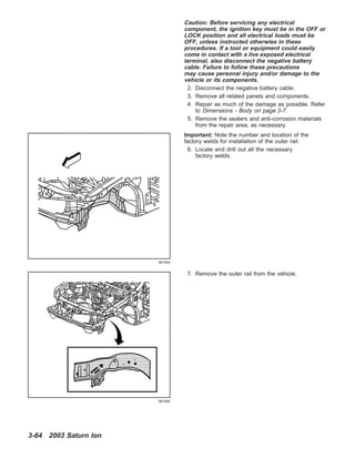
- 1. Caution: Before servicing any electrical component, the ignition key must be in the OFF or LOCK position and all electrical loads must be OFF, unless instructed otherwise in these procedures. If a tool or equipment could easily come in contact with a live exposed electrical terminal, also disconnect the negative battery cable. Failure to follow these precautions may cause personal injury and/or damage to the vehicle or its components. 2. Disconnect the negative battery cable. 3. Remove all related panels and components. 4. Repair as much of the damage as possible. Refer to Dimensions - Body on page 3-7. 5. Remove the sealers and anti-corrosion materials from the repair area, as necessary. Important: Note the number and location of the factory welds for installation of the outer rail. 6. Locate and drill out all the necessary factory welds. 7. Remove the outer rail from the vehicle. 867560 867565 3-64 2003 Saturn Ion
- 2. Installation Procedure Important: If the location of the original plug weld holes can not be determined, space the plug weld holes every 40 mm (11⁄2 in) apart. 1. Drill 8 mm (5/16 in) plug weld holes in the service part as necessary in the locations noted from the original panel. 2. Prepare all mating surfaces as necessary. 3. Apply 3M Weld-Thru Coating P/N 05916 or equivalent to all mating surfaces. 4. Position the outer rail to the vehicle using 3– dimensional measuring equipment. Clamp the outer rail in place. 5. Plug weld accordingly. 6. Clean and prepare all of the welded surfaces. 7. Install all of the related panels and components. 8. Apply the sealers and anti-corrosion materials to the repair area, as necessary. 9. Paint the repaired area. 10. Connect the negative battery cable. 11. Enable the SIR system. 865261 867565 867556 2003 Saturn Ion 3-65 2003SaturnIon
- 3. Suspension Support Replacement - Front Removal Procedure Caution: To avoid personal injury when exposed to welding flashes or to galvanized (Zinc Oxide) metal toxic fumes while grinding/cutting on any type of metal or sheet molded compound, you must work in a properly ventilated area, wearing an approved respirator, eye protection, earplugs, welding gloves, and protective clothing. Caution: When performing service on or near the SIR components or the SIR wiring, the SIR system must be disabled. Refer to SIR Disabling and Enabling Zones. Failure to observe the correct procedure could cause deployment of the SIR components, personal injury, or unnecessary SIR system repairs. 1. Disable the SIR system. Caution: Before servicing any electrical component, the ignition key must be in the OFF or LOCK position and all electrical loads must be OFF, unless instructed otherwise in these procedures. If a tool or equipment could easily come in contact with a live exposed electrical terminal, also disconnect the negative battery cable. Failure to follow these precautions may cause personal injury and/or damage to the vehicle or its components. 2. Disconnect the negative battery cable. 3. Remove all related panels and components. 4. Repair as much of the damage as possible. Refer to Dimensions - Body on page 3-7. 5. Remove the sealers and anti-corrosion materials from the repair area, as necessary. Important: Note the number and location of the factory welds for installation of the front suspension support. 6. Locate and drill out all the necessary factory welds. 867622 867626 3-66 2003 Saturn Ion
- 4. 7. Remove the front suspension support. Installation Procedure Important: If the location of the original plug weld holes can not be determined, space the plug weld holes every 40 mm (11⁄2 in) apart. 1. Drill 8 mm (5/16 in) plug weld holes in the service part as necessary in the locations noted from the original panel. 2. Prepare all mating surfaces as necessary. 3. Apply 3M Weld-Thru Coating P/N 05916 or equivalent to all mating surfaces. 4. Position the front suspension support to the vehicle using 3–dimensional measuring equipment. Clamp the support into place. 867629 865265 867629 2003 Saturn Ion 3-67 2003SaturnIon
- 5. 5. Plug weld accordingly. 6. Clean and prepare all of the welded surfaces. 7. Install all of the related panels and components. 8. Apply the sealers and anti-corrosion materials to the repair area, as necessary. 9. Paint the repaired area. 10. Connect the negative battery cable. 11. Enable the SIR system. Extension Replacement Front Compartment Side Rail - Rear Removal Procedure Caution: To avoid personal injury when exposed to welding flashes or to galvanized (Zinc Oxide) metal toxic fumes while grinding/cutting on any type of metal or sheet molded compound, you must work in a properly ventilated area, wearing an approved respirator, eye protection, earplugs, welding gloves, and protective clothing. Caution: When performing service on or near the SIR components or the SIR wiring, the SIR system must be disabled. Refer to SIR Disabling and Enabling Zones. Failure to observe the correct procedure could cause deployment of the SIR components, personal injury, or unnecessary SIR system repairs. 1. Disable the SIR system. Caution: Before servicing any electrical component, the ignition key must be in the OFF or LOCK position and all electrical loads must be OFF, unless instructed otherwise in these procedures. If a tool or equipment could easily come in contact with a live exposed electrical terminal, also disconnect the negative battery cable. Failure to follow these precautions may cause personal injury and/or damage to the vehicle or its components. 2. Disconnect the negative battery cable. 3. Remove all related panels and components. 4. Repair as much of the damage as possible. Refer to Dimensions - Body on page 3-7. 867622 867632 3-68 2003 Saturn Ion
- 6. 5. Remove the sealers and anti-corrosion materials from the repair area, as necessary. Important: Note the number and location of the factory welds for installation of the rear extension of the front compartment side rail. 6. Locate and drill out all the necessary factory welds. 7. Remove the rear extension. Installation Procedure Important: If the location of the original plug weld holes can not be determined, space the plug weld holes every 40 mm (11⁄2 in) apart. 1. Drill 8 mm (5/16 in) plug weld holes in the service part as necessary in the locations noted from the original panel. 2. Prepare all mating surfaces as necessary. 3. Apply 3M Weld-Thru Coating P/N 05916 or equivalent to all mating surfaces. 867635 867636 865268 2003 Saturn Ion 3-69 2003SaturnIon
- 7. 4. Position the rear extension to the vehicle using 3– dimensional measuring equipment. Clamp the support into place. 5. Plug weld accordingly. 6. Clean and prepare all of the welded surfaces. 7. Install all of the related panels and components. 8. Apply the sealers and anti-corrosion materials to the repair area, as necessary. 9. Paint the repaired area. 10. Connect the negative battery cable. 11. Enable the SIR system. Windshield Frame Reinforcement Replacement - Inner Upper Removal Procedure Caution: To avoid personal injury when exposed to welding flashes or to galvanized (Zinc Oxide) metal toxic fumes while grinding/cutting on any type of metal or sheet molded compound, you must work in a properly ventilated area, wearing an approved respirator, eye protection, earplugs, welding gloves, and protective clothing. Caution: Refer to SIR Caution on page 1-1 in General Information. 1. Disable the SIR system. 867636 867632 875595 3-70 2003 Saturn Ion
- 8. Caution: Before servicing any electrical component, the ignition key must be in the OFF or LOCK position and all electrical loads must be OFF, unless instructed otherwise in these procedures. If a tool or equipment could easily come in contact with a live exposed electrical terminal, also disconnect the negative battery cable. Failure to follow these precautions may cause personal injury and/or damage to the vehicle or its components. 2. Disconnect the negative battery cable. 3. Remove all related panels and components. 4. Repair as much of the damage as possible. Refer to Dimensions - Body on page 3-7. 5. Remove the sealers and anti-corrosion materials from the repair area, as necessary. Important: Note the number and location of the factory welds for installation of the windshield frame reinforcement. 6. Locate and drill out all the necessary factory welds. 7. Remove the windshield frame reinforcement. 875601 875604 2003 Saturn Ion 3-71 2003SaturnIon
- 9. Installation Procedure Important: If the location of the original plug weld holes can not be determined, space the plug weld holes every 40 mm (11⁄2 in) apart. 1. Drill 8 mm (5/16 in) plug weld holes in the service part as necessary in the locations noted from the original panel. 2. Prepare all mating surfaces as necessary. 3. Apply 3M Weld-Thru Coating P/N 05916 or equivalent to all mating surfaces. 4. Position the windshield frame reinforcement to the vehicle. 5. Plug weld accordingly. 6. Clean and prepare all of the welded surfaces. 7. Install all of the related panels and components. 8. Apply the sealers and anti-corrosion materials to the repair area, as necessary. 9. Paint the repaired area. 10. Connect the negative battery cable. 11. Enable the SIR system. 875599 875604 875595 3-72 2003 Saturn Ion
- 10. Hinge Pillar Body Reinforcement Replacement - Front Inner Removal Procedure Caution: To avoid personal injury when exposed to welding flashes or to galvanized (Zinc Oxide) metal toxic fumes while grinding/cutting on any type of metal or sheet molded compound, you must work in a properly ventilated area, wearing an approved respirator, eye protection, earplugs, welding gloves, and protective clothing. Caution: When performing service on or near the SIR components or the SIR wiring, the SIR system must be disabled. Refer to SIR Disabling and Enabling Zones. Failure to observe the correct procedure could cause deployment of the SIR components, personal injury, or unnecessary SIR system repairs. 1. Disable the SIR system. Caution: Before servicing any electrical component, the ignition key must be in the OFF or LOCK position and all electrical loads must be OFF, unless instructed otherwise in these procedures. If a tool or equipment could easily come in contact with a live exposed electrical terminal, also disconnect the negative battery cable. Failure to follow these precautions may cause personal injury and/or damage to the vehicle or its components. 2. Disconnect the negative battery cable. 3. Remove all related panels and components. 4. Remove the sealers and anti-corrosion materials from the repair area, as necessary. 5. Repair as much of the damaged area as possible. Refer to Dimensions - Body on page 3-7. Important: Note the number and location of the factory welds for installation of the hinge pillar. 6. Locate and drill out all factory welds 875620 875622 2003 Saturn Ion 3-73 2003SaturnIon
- 11. 7. Remove the damaged hinge pillar reinforcement. Installation Procedure Important: If the location of the original plug weld holes can not be determined, space the plug weld holes every 40 mm (1 1/2 in) apart. 1. Drill 8 mm (5/16 in) plug weld holes in the service part as necessary as noted from the original panel. 2. Prepare all mating surfaces as necessary. 3. Apply 3M Weld-Thru Coating P/N 05916 or equivalent to all mating surfaces. 4. Align the service part using 3-dimensional measuring equipment. Clamp in place. 5. Plug weld accordingly. 6. Clean and prepare all of the welded surfaces. 7. Apply the sealers and anti-corrosion materials to the repair area, as necessary. 8. Paint the repaired area. 9. Install all of the related panels and components. 10. Connect the negative battery cable. 11. Enable the SIR system. 875623 875621 875620 3-74 2003 Saturn Ion
- 12. Hinge Pillar Body Replacement - Front Inner Removal Procedure Caution: To avoid personal injury when exposed to welding flashes or to galvanized (Zinc Oxide) metal toxic fumes while grinding/cutting on any type of metal or sheet molded compound, you must work in a properly ventilated area, wearing an approved respirator, eye protection, earplugs, welding gloves, and protective clothing. Caution: When performing service on or near the SIR components or the SIR wiring, the SIR system must be disabled. Refer to SIR Disabling and Enabling Zones. Failure to observe the correct procedure could cause deployment of the SIR components, personal injury, or unnecessary SIR system repairs. 1. Disable the SIR system. Caution: Before servicing any electrical component, the ignition key must be in the OFF or LOCK position and all electrical loads must be OFF, unless instructed otherwise in these procedures. If a tool or equipment could easily come in contact with a live exposed electrical terminal, also disconnect the negative battery cable. Failure to follow these precautions may cause personal injury and/or damage to the vehicle or its components. 2. Disconnect the negative battery cable. 3. Remove all related panels and components. 4. Repair as much of the damaged area as possible. Refer to Dimensions - Body on page 3-7. 5. Remove the sealers and anti-corrosion materials from the repair area, as necessary. Important: Note the number and location of the factory welds for installation of the inner hinge pillar. 6. Locate and drill out all the necessary factory welds. 870896 870899 2003 Saturn Ion 3-75 2003SaturnIon
- 13. Thank you very much for your reading. Please Click Here. Then Get COMPLETE MANUAL. NO WAITING NOTE: If there is no response to click on the link above, please download the PDF document first and then click on it.
- 14. 7. Remove the inner hinge pillar. Installation Procedure Important: If the location of the original plug weld holes can not be determined, space the plug weld holes every 40 mm (11⁄2 in) apart. 1. Drill 8 mm (5/16 in) plug weld holes in the service part as necessary in the locations noted from the original panel. 2. Prepare all mating surfaces as necessary. 3. Apply 3M Weld-Thru Coating P/N 05916 or equivalent to all mating surfaces. 4. Install the baffle in the inner portion of the front inner hinge pillar. 870901 870898 870903 3-76 2003 Saturn Ion
- 15. 5. Position the hinge pillar body to the vehicle. 6. Plug weld accordingly. 7. Clean and prepare all of the welded surfaces. 8. Install all of the related panels and components. 9. Apply the sealers and anti-corrosion materials to the repair area, as necessary. 10. Paint the repaired area. 11. Connect the negative battery cable. 12. Enable the SIR system. 870901 870896 2003 Saturn Ion 3-77 2003SaturnIon
- 16. Hinge Pillar Body Sectioning - Front Removal Procedure Caution: To avoid personal injury when exposed to welding flashes or to galvanized (Zinc Oxide) metal toxic fumes while grinding/cutting on any type of metal or sheet molded compound, you must work in a properly ventilated area, wearing an approved respirator, eye protection, earplugs, welding gloves, and protective clothing. Caution: Sectioning should be performed only in the recommended areas. Failure to do so may compromise the structural integrity of the vehicle and cause personal injury if the vehicle is in a collision. The sedan body side outer panel is available either in one piece or in front or rear portions. The front and the rear halves are cut about half way across the rear door opening. You can perform any one of these replacement procedures separately or in any combination, depending upon the extent of damage to the vehicle. Sectioning must take place in specified areas only. Stay away from the door and window opening radius areas. Section only in straight areas of the openings. The coupe body side outer panel is available as a one-piece panel only. You can perform any one of these replacement procedures separately or in any combination, depending upon the extent of the damage to the vehicle. Sectioning must take place in specified areas only. Stay away from the door and window opening radius areas. Section only in straight areas of the openings. 874221 874304 3-78 2003 Saturn Ion
- 17. Caution: When performing service on or near the SIR components or the SIR wiring, the SIR system must be disabled. Refer to SIR Disabling and Enabling Zones. Failure to observe the correct procedure could cause deployment of the SIR components, personal injury, or unnecessary SIR system repairs. 1. Disable the SIR system. Caution: Before servicing any electrical component, the ignition key must be in the OFF or LOCK position and all electrical loads must be OFF, unless instructed otherwise in these procedures. If a tool or equipment could easily come in contact with a live exposed electrical terminal, also disconnect the negative battery cable. Failure to follow these precautions may cause personal injury and/or damage to the vehicle or its components. 2. Disconnect the negative battery cable. 3. Remove all related panels and components. 4. Repair as much of the damaged area as possible. Refer to Dimensions - Body on page 3-7. 5. Remove the sealers and anti-corrosion materials from the repair area, as necessary. Important: Sectioning can be done anywhere in the straight areas of the windshield pillar and along the rocker panel. 6. Locate the area on the panel where sectioning will be performed. 7. Measure from any trim attachment hole within the recommended sectioning areas. Mark the location for section cutting on the vehicle at the windshield pillar and rocker panel locations. Important: Note the number and location of the factory welds for installation of the hinge pillar. 8. Locate and drill out all factory welds. 876963 876965 2003 Saturn Ion 3-79 2003SaturnIon