
Recommended
More Related Content
What's hot
What's hot (10)
Similar to 2001 toyota avalon service repair manual
Similar to 2001 toyota avalon service repair manual (16)
More from fjjfyjsekdmme
More from fjjfyjsekdmme (20)
Recently uploaded
Recently uploaded (20)
2001 toyota avalon service repair manual
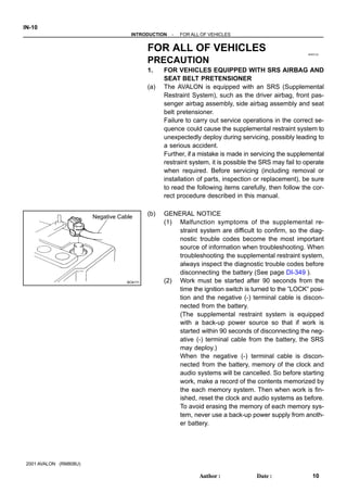
- 1. IN0ED-02 BO4111 Negative Cable IN-10 - INTRODUCTION FOR ALL OF VEHICLES 10 Author: Date: 2001 AVALON (RM808U) FOR ALL OF VEHICLES PRECAUTION 1. FOR VEHICLES EQUIPPED WITH SRS AIRBAG AND SEAT BELT PRETENSIONER (a) The AVALON is equipped with an SRS (Supplemental Restraint System), such as the driver airbag, front pas- senger airbag assembly, side airbag assembly and seat belt pretensioner. Failure to carry out service operations in the correct se- quence could cause the supplemental restraint system to unexpectedly deploy during servicing, possibly leading to a serious accident. Further, if a mistake is made in servicing the supplemental restraint system, it is possible the SRS may fail to operate when required. Before servicing (including removal or installation of parts, inspection or replacement), be sure to read the following items carefully, then follow the cor- rect procedure described in this manual. (b) GENERAL NOTICE (1) Malfunction symptoms of the supplemental re- straint system are difficult to confirm, so the diag- nostic trouble codes become the most important source of information when troubleshooting. When troubleshooting the supplemental restraint system, always inspect the diagnostic trouble codes before disconnecting the battery (See page DI-349 ). (2) Work must be started after 90 seconds from the time the ignition switch is turned to the ”LOCK” posi- tion and the negative (-) terminal cable is discon- nected from the battery. (The supplemental restraint system is equipped with a back-up power source so that if work is started within 90 seconds of disconnecting the neg- ative (-) terminal cable from the battery, the SRS may deploy.) When the negative (-) terminal cable is discon- nected from the battery, memory of the clock and audio systems will be cancelled. So before starting work, make a record of the contents memorized by the each memory system. Then when work is fin- ished, reset the clock and audio systems as before. To avoid erasing the memory of each memory sys- tem, never use a back-up power supply from anoth- er battery.
- 2. F03856 Marks - INTRODUCTION FOR ALL OF VEHICLES IN-1 1 11 Author: Date: 2001 AVALON (RM808U) (3) Even in cases of a minor collision where the SRS does not deploy, the steering wheel pad, front pas- senger airbag assembly, side airbag assembly and seat belt pretensioner should be inspected (See page RS- 15, RS- 30, RS- 44, RS- 57 and BO-130 ). (4) Never use SRS parts from another vehicle. When replacing parts, replace them with new parts. (5) Before repairs, remove the airbag sensor if shocks are likely to be applied to the sensor during repairs. (6) Never disassemble and repair the airbag sensor as- sembly, steering wheel pad, front passenger airbag assembly, side airbag assembly or seat belt preten- sioner. (7) If the airbag sensor assembly, steering wheel pad, front passenger airbag assembly, side airbag as- sembly or seat belt pretensioner has been dropped, or if there are cracks, dents or other defects in the case, bracket or connector, replace them with new ones. (8) Do not directly expose the airbag sensor assembly, steering wheel pad, front passenger airbag assem- bly, side airbag assembly or seat belt pretensioner to hot air or flames. (9) Use a volt/ohmmeter with high impedance (10 kΩ/V minimum) for troubleshooting of the electrical cir- cuit. (10) Information labels are attached to the periphery of the SRS components. Follow the instructions on the notices. (11) After work on the supplemental restraint system is completed, check the SRS warning light (See page DI-349 ). (c) SPIRAL CABLE (in Combination Switch) The steering wheel must be fitted correctly to the steering column with the spiral cable at the neutral position, other- wise cable disconnection and other troubles may result. Refer to SR-22 of this manual concerning correct steer- ing wheel installation.
- 3. B09710 Example: Correct Wrong Z13950 Example: IN-12 - INTRODUCTION FOR ALL OF VEHICLES 12 Author: Date: 2001 AVALON (RM808U) (d) STEERING WHEEL PAD (with Airbag) (1) When removing the steering wheel pad or handling a new steering wheel pad, it should be placed with the pad top surface facing up. Storing the pad with its metallic surface facing up- ward may lead to a serious accident if the airbag de- ploys for some reason. In addition do not store a steering wheel pad on top of another one. (2) Never measure the resistance of the airbag squib. (This may cause the airbag to deploy, which is very dangerous.) (3) Grease should not be applied to the steering wheel pad and the pad should not be cleaned with deter- gents of any kind. (4) Store the steering wheel pad where the ambient temperature remains below 93°C (200°F), without high humidity and away from electrical noise. (5) When using electric welding, first disconnect the air- bag connector (yellow color and 2 pins) under the steering column near the combination switch con- nector before starting work. (6) When disposing of a vehicle or the steering wheel pad alone, the airbag should be deployed using an SST before disposal (See page RS-17 ). Carry out the operation in a safe place away from electrical noise.
- 4. B02921 Example: Correct Wrong Z13951 Example: - INTRODUCTION FOR ALL OF VEHICLES IN-13 13 Author: Date: 2001 AVALON (RM808U) (e) FRONT PASSENGER AIRBAG ASSEMBLY (1) Always store a removed or new front passenger air- bag assembly with the airbag deployment direction facing up. Storing the airbag assembly with the airbag deploy- ment direction facing down could cause a serious accident if the airbag inflates. (2) Never measure the resistance of the airbag squib. (This may cause the airbag to deploy, which is very dangerous.) (3) Grease should not be applied to the front passen- ger airbag assembly and the airbag door should not be cleaned with detergents of any kind. (4) Store the airbag assembly where the ambient tem- perature remains below 93°C (200°F), without high humidity and away from electrical noise. (5) When using electric welding, first disconnect the air- bag connector (yellow color and 2 pins) installed on the assembly before starting work. (6) When disposing of a vehicle or the airbag assembly alone, the airbag should be deployed using an SST before disposal (See page RS-32 ). Perform the operation in a safe place away from electrical noise.
- 5. B02922 Example: Correct Wrong N21642 Example: IN-14 - INTRODUCTION FOR ALL OF VEHICLES 14 Author: Date: 2001 AVALON (RM808U) (f) SIDE AIRBAG ASSEMBLY (1) Always store a removed or new side airbag assem- bly with the airbag deployment direction facing up. Storing the airbag assembly with the airbag deploy- ment direction facing down could cause a serious accident if the airbag deploys. (2) Never measure the resistance of the airbag squib. (This may cause the airbag to deploy, which is very dangerous.) (3) Grease should not be applied to the side airbag as- sembly and the surface should not be cleaned with detergents of any kind. (4) Store the airbag assembly where the ambient tem- perature remains below 93°C (200°F), without high humidity and away from electrical noise. (5) When using electric welding, first disconnect the air- bag connector (yellow color and 2 pins) under the seat before starting work. (6) When disposing of a vehicle or the side airbag as- sembly alone, the airbag should be deployed using an SST before disposal (See page RS-45 ). Perform the operation in a safe place away from electrical noise.
- 6. B02121 Example: - INTRODUCTION FOR ALL OF VEHICLES IN-15 15 Author: Date: 2001 AVALON (RM808U) (g) SEAT BELT PRETENSIONER (1) Never measure the resistance of the seat belt pre- tensioner. (This may cause the seat belt pretension- er to activate, which is very dangerous.) (2) Never disassemble the seat belt pretensioner. (3) Never install the seat belt pretensioner in another vehicle. (4) Store the seat belt pretensioner where the ambient temperature remains below 80°C (176°F) and away from electrical noise without high humidity. (5) When using electric welding, first disconnect the connector (yellow color and 2 pins) before starting work. (6) When disposing of a vehicle or the seat belt preten- sioner alone, the seat belt pretensioner should be activated before disposal (See page BO-131 ). Per- form the operation in a safe place away from electri- cal noise. (7) The seat belt pretensioner is hot after activation, so let it cool down sufficiently before the disposal. However never apply water to the seat belt preten- sioner.
- 7. IN-16 - INTRODUCTION FOR ALL OF VEHICLES 16 Author: Date: 2001 AVALON (RM808U) (h) AIRBAG SENSOR ASSEMBLY (1) Never reuse the airbag sensor assembly involved in a collision when the SRS has deployed. (2) The connectors to the airbag sensor assembly should be connected or disconnected with the sen- sor mounted on the floor. If the connectors are con- nected or disconnected while the airbag sensor as- sembly is not mounted to the floor, it could cause undesired ignition of the supplemental restraint sys- tem. (3) Work must be started after 90 seconds from the time the ignition switch is turned to the ”LOCK” posi- tion and the negative (-) terminal cable is discon- nected from the battery, even if only loosing the set bolts of the airbag sensor assembly. (i) WIRE HARNESS AND CONNECTOR The SRS wire harness is integrated with the instrument panel wire harness assembly. All the connectors in the system are a standard yellow color. If the SRS wire har- ness becomes disconnected or the connector becomes broken due to an accident, etc., repair or replace it as shown on page RS-82 .
- 8. - INTRODUCTION FOR ALL OF VEHICLES IN-17 17 Author: Date: 2001 AVALON (RM808U) 2. FOR VEHICLES EQUIPPED WITH A CATALYTIC CONVERTER CAUTION: If large amount of unburned gasoline flows into the converter, it may overheat and create a fire haz- ard. To prevent this, observe the following precautions and explain them to your customer. (a) Use only unleaded gasoline. (b) Avoid prolonged idling. Avoid running the engine at idle speed for more than 20 minutes. (c) Avoid spark jump test. (1) Perform spark jump test only when absolutely necessary. Perform this test as rapidly as possible. (2) While testing, never race the engine. (d) Avoid prolonged engine compression measurement. Engine compression tests must be done as rapidly as possible. (e) Do not run engine when fuel tank is nearly empty. This may cause the engine to misfire and create an extra load on the converter. (f) Avoid coasting with ignition turned off. (g) Do not dispose of used catalyst along with parts contaminated with gasoline or oil. 3. IF VEHICLE IS EQUIPPED WITH MOBILE COMMUNICATION SYSTEM For vehicles with mobile communication systems such as two-way radios and cellular telephones, observe the following precautions. (1) Install the antenna as far as possible away from the ECU and sensors of the vehicle’s electronic system. (2) Install the antenna feeder at least 20 cm (7.87 in.) away from the ECU and sensors of the ve- hicle’s electronic systems. For details about ECU and sensors locations, refer to the section on the applicable component. (3) Avoid winding the antenna feeder together with other wiring as much as possible, and also avoid running the antenna feeder parallel with other wire harnesses. (4) Check that the antenna and feeder are correctly adjusted. (5) Do not install powerful mobile communications system. 4. FOR USING OBD II SCAN TOOL OR TOYOTA HAND-HELD TESTER CAUTION: Observe the following items for safety reasons: Before using the OBD II scan tool or TOYOTA hand-held tester, the OBD II scan tool’s instruc- tion book or TOYOTA hand-held tester’s operator manual should be read thoroughly. Be sure to route all cables securely when driving with the OBD II scan tool or TOYOTA hand- held tester connected to the vehicle. (i.e. Keep cables away from feet, pedals, steering wheel and shift lever.) Two persons are required when test driving with the OBD II scan tool or TOYOTA hand-held tester, one person to drive the vehicle and the other person to operate the OBD II scan tool or TOYOTA hand-held tester.
- 9. B09711 B09808 B09711 IN-18 - INTRODUCTION FOR ALL OF VEHICLES 18 Author: Date: 2001 AVALON (RM808U) 5. FOR VEHICLES EQUIPPED WITH TRACTION CON- TROL (TRAC) VEHICLE SKID CONTROL (VSC) SYS- TEM NOTICE: When replacing the steering angle sensor or ECU, or when adjusting the front wheel alignment or steering wheel center point in accordance with the removing and installing or replacing the suspension, axle, or steering parts, make sure to perform the steering angle sensor zero point calibration (See page DI-252 ). Do not remove or install the VSC related parts unless necessary. Otherwise, there is a possibility that the setting of the VSC to be affected. When working on the VSC related operation, make sure to check that the preparations before and after work are completed according to the following instruction. When using a drum tester such as a speedometer tes- ter or chassis dynamometer, etc., or jacking up the front wheels and driving the wheels, always push in the TRAC VSC cut (”VSC OFF”) switch and turn the TRAC VSC system OFF. (a) Press the VSC OFF switch. (b) Check that the VSC OFF indicator light comes ON. HINT: The VSC OFF indicator light should be always OFF when the engine is restarted. (c) Begin measurements. (d) Press the VSC OFF switch again to change the TRAC VSC system to operational condition and check that the VSC OFF indicator light goes off. HINT: The SLIP indicator light blinks when the TRAC system is operational. The SLIP indicator light blinks and the VSC buzzer sounds when the VSC system is operational.
- 10. IN05Y-17 - INTRODUCTION HOW TO TROUBLESHOOT ECU CONTROLLED SYSTEMS IN-19 19 Author: Date: 2001 AVALON (RM808U) HOW TO TROUBLESHOOT ECU CONTROLLED SYSTEMS GENERAL INFORMATION A large number of ECU controlled systems are used in the AVALON. In general, the ECU controlled system is considered to be a very intricate system requiring a high level of technical knowledge and expert skill to troubleshoot. However, the fact is that if you proceed to inspect the circuits one by one, troubleshooting of these systems is not complex. If you have adequate understanding of the system and a basic knowledge of electricity, accurate diagnosis and necessary repair can be performed to locate and fix the problem. This manual is designed through emphasis of the above standpoint to help service technicians perform accurate and effective troubleshooting, and is compiled for the following major ECU controlled systems: The troubleshooting procedure and how to make use of it are described on the following pages. System Page 1. Engine DI-1 2. Automatic Transaxle DI-158 3. Anti-Lock Brake System With Electronic Brake Force Distribution (EBD) DI-210 4. ABS With EBD BA TRAC VSC System DI-250 5. Supplemental Restraint System DI-347 6. Power Seat Control System (w/ Driving position memory) DI-488 7. Theft Deterrent System DI-517 8. Cruise Control System DI-549 9. Engine Immobilizer System DI-597 10.Body Control System DI-615 11.Driver Door Control System DI-676 12.Passenger Door Control System DI-700 13.Multiplex Communication System DI-718 14.Air Conditioning System DI-752 FOR USING OBD II SCAN TOOL OR TOYOTA HAND-HELD TESTER Before using the scan tool or tester, the scan tool’s instruction book or tester’s operator manual should be read thoroughly. If the scan tool or tester cannot communicate with ECU controlled systems when you have connected the cable of the scan tool or tester to DLC3, turned the ignition switch ON and operated the scan tool, there is a problem on the vehicle side or tool side. (1) If communication is normal when the tool is connected to another vehicle, inspect the diagnosis data link line (Busline) or ECU power circuit of the vehicle. (2) If communication is still not possible when the tool is connected to another vehicle, the problem is probably in the tool itself, so perform the Self Test procedures outline in the Tester Operator’s Manual.
- 11. Thank you very much for your reading. Please Click Here. Then Get COMPLETE MANUAL. NO WAITING NOTE: If there is no response to click on the link above, please download the PDF document first and then click on it.
- 12. IN05W-19 Vehicle Brought to Workshop Customer Problem Analysis Symptom Confirmation and Diagnostic Trouble Code Check Symptom Simulation Diagnostic Trouble Code Chart Problem Symptoms Table Circuit Inspection or Parts Inspection Repair Confirmation Test End 1 2 4 3 5 6 7 8 Ask the customer about the conditions and the environment when the problem occurred. 1 Confirm the symptoms and the problem conditions, and check the diagnostic trouble codes. (When the problem symptoms do not appear during confirmation, use the symptom simulation method described later on.) 2, 3 Check the results obtained in Step 2, then confirm the inspection procedure for the system or the part which should be checked using the diagnostic trouble code chart or the problem symptoms table. 4, 5, 6 Check and repair the affected system or part in accordance with the instructions in Step 6. 7 After completing repairs, confirm that the problem has been eliminated. (If the problem is not reproduced, perform the confirmation test under the same conditions and in the same environment as when it occurred for the first time.) 8 IN-20 - INTRODUCTION HOW TO TROUBLESHOOT ECU CONTROLLED SYSTEMS 20 Author: Date: 2001 AVALON (RM808U) HOW TO PROCEED WITH TROUBLESHOOTING Carry out troubleshooting in accordance with the procedure on the following page. Here, only the basic pro- cedure is shown. Details are provided in Diagnostics section, showing the most effective methods for each circuit. Confirm the troubleshooting procedures first for the relevant circuit before beginning troubleshooting of that circuit.
- 13. Important Points in the Customer Problem Analysis What ----- Vehicle model, system name When ----- Date, time, occurrence frequency Where ----- Road conditions Under what conditions? ----- Running conditions, driving conditions, weather conditions How did it happen? ----- Problem symptoms (Sample) Engine control system check sheet. ENGINE CONTROL SYSTEM Check Sheet Customer’s Name Driver’s Name Data Vehicle Brought in License No. Model and Model Year Frame No. Engine Model Odometer Reading km miles Problem Symptoms Engine does not Start Difficult to Start Poor Idling Poor Drive ability Engine Stall Others Engine does not crank No initial combustion No complete combustion Engine cranks slowly Other Incorrect first idle Idling rpm is abnormal High ( rpm) Low ( rpm) Rough idling Other Hesitation Back fire Muffler explosion (after-fire) Surging Knocking Other Soon after starting After accelerator pedal depressed After accelerator pedal released During A/C operation Shifting from N to D Other Data Problem Constant Sometimes ( times per day/month) Inspector’s Name CUSTOMER PROBLEM ANALYSIS CHECK - INTRODUCTION HOW TO TROUBLESHOOT ECU CONTROLLED SYSTEMS IN-21 21 Author: Date: 2001 AVALON (RM808U) 1. CUSTOMER PROBLEM ANALYSIS In troubleshooting, the problem symptoms must be confirmed accurately and all preconceptions must be cleared away in order to give an accurate judgment. To ascertain just what the problem symptoms are, it is extremely important to ask the customer about the problem and the conditions at the time it occurred. Important Point in the Problem Analysis: The following 5 items are important points in the problem analysis. Past problems which are thought to be unrelated and the repair history, etc. may also help in some cases, so as much information as possible should be gathered and its relationship with the problem symptoms should be correctly ascertained for reference in troubleshooting. A customer problem analysis table is provided in Diagnostics section for each system for your use.
- 14. DIAGNOSTIC TROUBLE CODE CHECK PROCEDURE Diagnostic Trouble Code Check (Make a note of and then clear) Confirmation of Symptoms Diagnostic Trouble Code Check Problem Condition Diagnostic Trouble Code Display Problem symptoms exist Same diagnostic trouble code is displayed Problem is still occurring in the diagnostic circuit Normal code is displayed The problem is still occurring in a place other than in the diagnostic circuit (The diagnostic trouble code displayed first is either for a past problem or it is a secondary problem) No problem symptoms exist The problem occurred in the diagnostic circuit in the past Normal Code Display Problem symptoms exist Normal code is displayed The problem is still occurring in a place other than in the diagnostic circuit No problem symptoms exist Normal code is displayed The problem occurred in a place other than in the diagnostic circuit in the past IN-22 - INTRODUCTION HOW TO TROUBLESHOOT ECU CONTROLLED SYSTEMS 22 Author: Date: 2001 AVALON (RM808U) 2. SYMPTOM CONFIRMATION AND DIAGNOSTIC TROUBLE CODE CHECK The diagnostic system in the AVALON fulfills various functions. The first function is the Diagnostic Trouble Code Check in which a malfunction in the signal circuits to the ECU is stored in code in the ECU memory at the time of occurrence, to be output by the technician during troubleshooting. Another function is the Input Signal Check which checks if the signals from various switches are sent to the ECU correctly. By using these check functions, the problem areas can be narrowed down quickly and troubleshooting can be performed effectively. Diagnostic functions are incorporated in the following systems in the AVALON. System Diagnostic Trouble Code Check Input Signal Check (Sensor Check) Diagnostic Test Mode (Active Test) Engine Automatic Transaxle Anti-Lock Brake System With Electronic Brake Force Distribution (EBD) ABS With EBD BA TRAC VSC System Supplemental Restraint System Cruise Control System Engine Immobilizer System Multiplex Communication System Air Conditioning System (with Check Mode) (with Check Mode) In diagnostic trouble code check, it is very important to determine whether the problem indicated by the diag- nostic trouble code is still occurring or occurred in the past but returned to normal at present. In addition, it must be checked in the problem symptom check whether the malfunction indicated by the diagnostic trouble code is directly related to the problem symptom or not. For this reason, the diagnostic trouble codes should be checked before and after the symptom confirmation to determine the current conditions, as shown in the table below. If this is not done, it may, depending on the case, result in unnecessary troubleshooting for normally operating systems, thus making it more difficult to locate the problem, or in repairs not pertinent to the problem. Therefore, always follow the procedure in correct order and perform the diagnostic trouble code check.
- 15. Diagnostic trouble code check Making a note of and clearing of the diagnostic trouble codes displayed Symptom confirmation No problem symptoms exist Problem symptoms exist Simulation test using the symptom simulation methods Normal code displayed Problem symptoms exist Normal code displayed No problem symptoms exist Diagnostic trouble code check Troubleshooting of problem indicated by diagnostic trouble code Diagnostic trouble code displayed Problem symptoms exist System Normal Troubleshooting of each problem symptom If a diagnostic trouble code was displayed in the initial diagnostic trouble code check, it indicates that the trouble may have occurred in a wire harness or connector in that circuit in the past. Therefore, check the wire harness and con- nectors (See page IN-30 ). - INTRODUCTION HOW TO TROUBLESHOOT ECU CONTROLLED SYSTEMS IN-23 23 Author: Date: 2001 AVALON (RM808U) Taking into account the points on the previous page, a flow chart showing how to proceed with troubleshoot- ing using the diagnostic trouble code check is shown below. This flow chart shows how to utilize the diagnos- tic trouble code check effectively, then by carefully checking the results, indicates how to proceed either to diagnostic trouble code troubleshooting or to troubleshooting of problem symptoms table.
- 16. V07268 VIBRATION METHOD: When vibration seems to be the major cause. CONNECTORS WIRE HARNESS PARTS AND SENSOR 1 Slightly shake the connector vertically and horizontally. Slightly shake the wire harness vertically and horizontally. The connector joint, fulcrum of the vibration, and body through portion are the major areas to be checked thorough- ly. Apply slight vibration with a finger to the part of the sensor considered to be the problem cause and check that the mal- function occurs. Shake Slightly Swing Slightly Vibrate Slightly HINT: Applying strong vibration to relays may result in open relays. IN-24 - INTRODUCTION HOW TO TROUBLESHOOT ECU CONTROLLED SYSTEMS 24 Author: Date: 2001 AVALON (RM808U) 3. SYMPTOM SIMULATION The most difficult case in troubleshooting is when there are no problem symptoms occurring. In such cases, a thorough customer problem analysis must be carried out, then simulate the same or similar conditions and environment in which the problem occurred in the customer’s vehicle. No matter how much experience a technician has, or how skilled he may be, if he proceeds to troubleshoot without confirming the problem symptoms he will tend to overlook something important in the repair operation and make a wrong guess somewhere, which will only lead to a standstill. For example, for a problem which only occurs when the en- gine is cold, or for a problem which occurs due to vibration caused by the road during driving, etc., the prob- lem can never be determined so long as the symptoms are confirmed with the engine hot condition or the vehicle at a standstill. Since vibration, heat or water penetration (moisture) is likely cause for problem which is difficult to reproduce, the symptom simulation tests introduced here are effective measures in that the ex- ternal causes are applied to the vehicle in a stopped condition. Important Points in the Symptom Simulation Test: In the symptom simulation test, the problem symptoms should of course be confirmed, but the problem area or parts must also be found out. To do this, narrow down the possible problem circuits according to the symp- toms before starting this test and connect a tester beforehand. After that, carry out the symptom simulation test, judging whether the circuit being tested is defective or normal and also confirming the problem symp- toms at the same time. Refer to the problem symptoms table for each system to narrow down the possible causes of the symptom.
- 17. B02389 B02390 HEAT METHOD: When the problem seems to occur when the suspect area is heated. 2 NOTICE: 3 WATER SPRINKLING METHOD: (1) (2) 4 OTHER: When a malfunction seems to occur when electrical load is excessive. When the malfunction seems to occur on a rainy day or in a high-humidity condition. Heat the component that is the likely cause of the malfunction with a hair dryer or similar object. Check to see if the malfunction occurs. Sprinkle water onto the vehicle and check to see if the malfunc- tion occurs. Turn on all electrical loads including the heater blower, head lights, rear window defogger, etc. and check to see if the mal- function occurs. ON HINT: If a vehicle is subject to water leakage, the leaked water may contaminate the ECU. When testing a vehicle with a water leak- age problem, special caution must be taken. M a l f u n c- tion Do not heat to more than 60 °C (140 °F). (Temperature is limited not to damage the components.) Do not apply heat directly to parts in the ECU. (1) (2) Never sprinkle water directly into the engine compart- ment, but indirectly change the temperature and hu- midity by applying water spray onto the radiator front surface. Never apply water directly onto the electronic compo- nents. NOTICE: - INTRODUCTION HOW TO TROUBLESHOOT ECU CONTROLLED SYSTEMS IN-25 25 Author: Date: 2001 AVALON (RM808U)