2. PART I
CONTENTS
1. Safety Instructions…………………………………….1
2. Constuction and Units …………………………………1-1
3. General Safety Remarks ………………………………1-2~3
4. Areas of Application ………………………………… 4
5. Machine Description ………………………………… 4
6. Description of the Safety Devices ……………………4
7. Basic Specifications ……………………………………
4
8. Minimum Requirements ………………………………4
9. Technical Data …………………………………………
5
10. Machine and Operating Elements………………………
6
11. Installation Diagram ………………………………… 7
12. Wiring Diagram ………………………………………8~9-1
13. Start-up and Functioning Sequence ……………………
10
14. Threading Diagram ……………………………………10
15. Strap Tension Adjustment ……………………………11
16. Maintenance and Lubrication…………………………12
17. Maintenance of the Unit………………………………12
3. 1. Safety Instructions
THIS MANUAL GIVES YOU INFORMATION ON SAFETY INSTRUCTIONS,
SPECIFICATIONS, OPERATION AND MAINTENANCE OF STRAPPING
MACHINES.
BEFORE OPERATING OR SERVICING THE MACHINE, PLEASE REVIEW
THE ENTIRE MANUAL AND FOLLOW THE SAFETY INSTRUCTIONS
CAREFULLY.
(1) Operation
a. Do not operate the machine with the table tops or covers removed.
b. Make sure the proper voltage is being used to operate the machine.
c. Never put any part of your body near, under or into a moving machine.
d. Do not operate the machine with any safety devices removed or disabled.
e. Follow instructions provided in this manual.
f. Only trained people should operate this machine.
g. Do not attempt to strap any part of your body.
h. Do not overload the machine by exceeding the performance limitations specified in
this manual.
(2) Maintenance
a. Shut off and lock out all electrical power before performing any maintenance
procedure.
b. Use the correct tools and parts to repair the machine.
c. Only trained people should service the machine.
d. Follow instructions provided in this manual.
(3) Additional Considerations
a. Do not touch the heater and the surrounding area. the heater operates at
approximately 340 C. Allow sufficient time for the heater to cool down.
b. The machine should be placed on a level floor and the surrounding area should .
be kept free of debris and discarded strap.
-1-
4. 2. Constuction and Units
1 Strapping head unit
4 Electric control unit
2 Body frame unit
3 Reel unit
-1-1-
5. 3. General Safety Remarks
( 1 ) Basic Operation
The manual and the safety remarks are to be read before use. The operator manual should
be kept with the machine at all times. Intervals for maintenance and inspections are to be
adhered to.
This machine was built with state of the art technology and rigid adherence to safety
standards.
Unless used properly, it can cause injury to operators or persons in close proximity to
the machine. In addition, improper use can cause damage to the machine or property around
the machine.
( 2 ) Basic Safety Precautions
The user is to be instructed in all other generally applicable legal and other mandatory
regulations relevant to accident prevention and environmental protection in addition
to the operating instructions.
For safety reasons,long hair must be tied back or otherwise secured, garments must be
close fitting and no jewelry may be worn.
Use protective equipment whenever required by circumstances or by law.
Carefully observe all safety instructions and warnings attached to the machine and make sure
that they are always complete and perfectly legible.
Always make certain that persons being trained and instructed in working on or with the
machine are permanently supervised by an experienced person.
Work on the electrical system and equipment of the machine is only to be carried out by a
skilled electrician or by persons under the supervision and guidance of a skilled
electrician and in accordance with the rules and regulations of electrical engineering.
( 3 ) Safety Instructions Governing Specific Operational Phases
Avoid any operation mode that might be unsafe.
All necessary precautions to ensure that the machine is only used being in a safe
and reliable state are to be taken. The machine is only to be operated if all protective and
safety devices, including removable safety devices, emergency shut-off equipment,
noise-protection elements and exhaust systems are in right place and fully functional
6. The machine is to be checked for damage and defects at least once per work shift. Any
changes including the working behavior of the machine are to be reported to competent
persons immediately. If necessary, the machine is to be stopped and locked immediately.
In case of any malfunction the machine must be stopped and locked until the defect
has been eliminated.
Generally make sure that nobody is at risk before starting up the machine.
All personnel that will be operating this machine should be thoroughly trained in
all phases of operation and safety.
Always tighten unscrewed connections after maintenance and repair.
After completing maintenance and repair all safety devices removed for setting
up or repairing the machine must be reinstalled and checked for functionality prior to putting
the machine back into service.
To minimize the environmental impact all consumables and replaced parts
must be disposed of safely.
Before starting the machine check that the accessories have been stowed away safely.
Do not attempt any operation that may be a risk to the stability of the machine.
Do not step on conveying equipment.
( 4 ) Warning of Electrical Dangers
Only use original fuses with specified current rating. Switch off the machine
immediately in case of trouble in the electrical system.
Only a skilled electrician or specially instructed personnel under the supervision
of a skilled electrician may work on the electrical system and always in accordance
with the applicable electrical engineering rules.
The power supply should be disconnected from the machine before performing any
maintenance. After disconnecting the power supply, it is essential to verify that the
machine is not getting power before proceeding. In addition, always check for proper
grounding.
7. The electrical equipment of the machine is to be checked and inspected at
regular intervals. Loose connections or scorched wires must be replaced at once.
If maintenance must be performed on the machine while still connected to a power
source, or in a "live" mode, always have a stand by person ready to disconnect the
power immediately, if necessary. The work area should always be marked by safety
tape in accordance with the applicable regulations. Please always use only properly
insulated tools.
Ground the feeder cable and any components with a ground rod before starting to
work on high-voltage assemblies, always disconnect the power supply before grounding.
Before restarting the machine carefully refit and fasten all parts removed for transport.
Always disconnect the power supply before moving the machine.
( 5 ) Grounding Instructions Shall Include the Following:
-GROUNDING INSTRUCTIONS
-This product should be grounded. In the event of an electrical short circuit, grounding
reduces the risk of electric shock by providing an escape wire for the electric current.
This product is equipped with a cord having a grounding wire with an appropriate
grounding plug. The plug must be plugged into an outlet that is properly installed and
grounded in accordance with all local codes and ordinances.
-DANGER- Improper installation of the grounding plug bears the risk of electrocution
shock. If repair or replacement of the cord or plug is necessary, do not connect the
grounding wire to any of the flat blade terminals. The wire with a green insulation sheath
(with or without yellow stripes) is the grounding wire.
-Check with a qualified electrician or serviceman if the grounding instructions are not
completely understood, or if in doubt as to whether the product is properly grounded.
Do not modify the plug provided; if it will not fit the outlet, have the proper outlet installed
by a qualified electrician.
-This product is for use on a nominal 110(220/230/240)-volt circuit and has a grounding plug.
Make sure that the product is connected to an outlet having the same configuration as the
plug.
( 6 ) Extension Cords:
Only use a 3-wire extension cord that has a 3-blade grounding plug, and a 3-slot receptacle
suitable for the plug of the product. Make sure your extension cord is in good condition.
When using an extension cord, be sure to use the right cable size to carry the load of your
product. A cord of unsufficient capacity will cause a drop in line voltage resulting in loss of
power and overheating. Refer to the following table:
Length (ft) 25 50 100 150 200 250 300 400 500
Gauge 16 14 10 8 6 6 6 4 4
8. 4. Areas of Application
This plastic strapping machine can be used for a wide range of applications where the
minimum package width is at least 80mm, and the minimum height is 30mm. When equipped
with a "small package option ", the machine is acceptable for packages as small as 50mm
wide and 30mm high.
This machine is particularly suitable for heavy packaged goods as well as printed
products, boxes, etc.
5. Machine Description
Semi-automatic plastic strapping machine for use with polypropylene strapping
Heavy duty construction
Simple, safe and user-friendly operation
Moveable, with large table area high capacity strap reel and stainless steel table
Two locking castors, to ensure safe operation
Extremely low-noise sealing unit
Strap tension adjustable from low to extremely high with infinitely variable strap feed.
6. Description of the Safety Devices
The machine is ready to operate when connected to the main power supply and
the main switch QS1 is switched to ON position. It takes approximately 1.5 minute for the
heating element to reach its operating temperature.
The machine is switched on and off with the main switch QS1 located on the machine
front operating panel.
7. Basic Specifications
System configuration 1L+N+PE 1L+N+PE
Nominal power 0.5KW 0.5KW
Rated current 2A 3A
Rated voltage 220V/230V/240V 110V
Rated frequency 50Hz 60Hz
Type of current AC AC
8. Minimum Requirements
( 1 ) The machine must only be operated in dry rooms.
( 2 ) The electrical supply line for the machine must have a minimum
cross-section of at least 3×1.0mm2.
9.
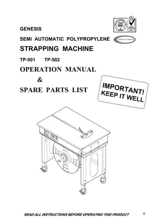
10. 10. Machine and Operating Elements
1. Main power switch
2. Ready lamp, lamp will light up on when proper sealing temperature is reached
3. Feed length knob, strap feed length
4. Selector switch, strap feed and reset
5. Tension adjustment knob, strap tension adjustment
6. Table top
7. Strap reel
8. Castor, two lockable two free
9. Adjustable legs
10. Frame
11. Door For TP-501
-6-
11.
12. 12. Wiring Diagram
a.For TP-501/TP-502
3
1
4
2
A
A
B
B
C
C
MACHINE MODEL
D
D
E
E
PAGE
F
F
3
1
4
2
-8-
13. A B C D E F
4 4
3 3
-8-1-
2 2
a.For TP-501/TP-502
1 1
A B C D E F
MACHINE MODEL PAGE
14. b. For TP-501CE/TP-502CE (For TUV Certified Version)
3
1
4
2
A
A
B
B
C
C
MACHINE MODEL
D
D
E
E
PAGE
F
F
3
4
1
2
-9-
15. b. For TP-501CE/TP-502CE (For TUV Certified Version)
3
1
4
2
A
A
B
B
C
C
MACHINE MODEL
D
D
E
E
PAGE
F
F
3
4
1
2
-9-1-
16.
17.
18. 16. Maintenance and Lubrication
Maintenance:
To ensure that the semi-automatic strapping machine is always ready for proper and
reliable operation keep to regular and attentive maintenance.
Keep the machine clean and take particular care of the strap guides.
Any small particles of loose strap should always be removed from all parts of the
machine. In addition to the strap guides, the strap feed devices of the unit, the
tops of the dies and the feed devices on the strap accumulator have to be blown
free of any dust at least once per week.
Lubrication:
The dies on the unit have to be lightly lubricated weekly.
17. Maintenance of the Unit
Lubricate the marked points weekly. Use only resin-free branded oil for
lubrication. All other assemblies are maintenace free. The strap guides and
the sealing unit have to be kept clean! Do not oil feedrollers.
Note:Any other servicing shall be performed by an authorized service
representative.
-12-
20. PART
CONTENTS
1. Strapping Head Unit ………………………………… 1~17
2. Body Frame Unit ……………………………………. 18~22
3. Reel Unit ……………………………………………..23~25
4. Electric Control Unit …………………………………26~31
41. 2 BODY FRAME UNIT T5-2-90001
T5-2-90002
REF.
PART NO. DESCRIPTION Q'TY REMARKS
NO.
T5-2-90001 Body Frame Unit (For TP-501) 1
T5-2-90002 Body Frame Unit (For TP-502) 1
1 T5-2-10004 Body Frame Group (For TP-501) 1 SEE PAGE 19
T5-2-10003 Body Frame Group (For TP-502) 1 SEE PAGE 19
2 T5-2-20000 Table Top Group 1 SEE PAGE 23
-18-
49. 4 ELECTRIC CONTROL UNIT T5-4-90007
T5-4-90008
REF.
PART NO. DESCRIPTION Q'TY REMARKS
NO.
T5-4-90007 Electric Control Unit 1
(For Standard, CE , CSA-UL Version)
T5-4-90008 Electric Control Unit (For with Display) 1
(For Standard, CE , CSA-UL Version)
(Option)
1 T5-4-10004 Electric Control Group 1 SEE PAGE 27
(For Standard, CE , CSA-UL Version)
T5-4-10005 Electric Control Group (For TUV CE Version) 1 SEE PAGE 27
(Option)
T5-4-20004 Electric Control Group (For with Display) 1 SEE PAGE 27
(For Standard, CE , CSA-UL Version)
(Option)
T5-4-20005 Electric Control Group (For with Display) 1 SEE PAGE 27
(For TUV CE Version)(Option)
3 T5-4-30000 Indicator Group (For with Metric Display) 1 SEE PAGE 30
(Option)
T5-4-30001 Indicator Group(For with Imperial 1 SEE PAGE 30
Display) (Option)
-26-
50.
51. 4-1 ELECTRIC CONTROL GROUP T5-4-10004
T5-4-20004
REF.
PART NO. DESCRIPTION Q'TY REMARKS
NO.
T5-4-10004 Electric Control Group 1
(For Standard, CE , CSA-UL Version)
T5-4-10005 Electric Control Group (For TUV 1
CE Version)(Option)
T5-4-20004 Electric Control Group (For with 1
Display) (For Standard, CE ,
CSA-UL Version) (Option)
T5-4-20005 Electric Control Group (For with 1
Display)(For TUV CE Version)(Option)
1 T5-4-10111 Box 1
2 T5-4-10120 Cover 1
3 T5-4-10130 Transformer (For 220V/230V/240V) 1
T5-4-10131 Transformer (For 110V) 1
4 T5-4-10142 P.C.B. 1
T5-4-20502 P.C.B.(For Machine With Display 1
For Metric Size) (Option)
T5-4-20512 P.C.B. (For Machine With Display 1
For Imperial Size) (Option)
5 LA-20055 Label 1
6 T5-4-10160 Fuse Holder 5
7 T6-6-30032 Fuse (For 110V/3A) 2
T6-6-30031 Fuse (For 220V/230V/240V/2A) 2
8 T6-6-30036 Fuse (1A) 1
9 T6-6-30133 Fuse (10A) 2
11 T5-4-10210 Jog Switch 1
12 T5-4-10221 Knob 2
13 T5-4-10231 Variable Resistor (5K) 2
14 T5-4-10580 Grommet 2
15 TK-001 Main Power Switch 1
16 T5-4-10260 Ready Lamp 1
18 TG-036 Selector Switch (Feed/Reset) 1
20 LA-10015 Label 1
21 T5-4-10310 Earth Plate (5P) 1