More Related Content Similar to 2002 lexus gx470 service repair manual (7) More from fujjsekfkksekm (20) 1. 2007 ENGINE
Engine Mechanical - GX 470
ENGINE
ON-VEHICLE INSPECTION
1. INSPECT ENGINE COOLANT
HINT:
(See ON-VEHICLE INSPECTION )
2. INSPECT ENGINE OIL
HINT:
(See ON-VEHICLE INSPECTION )
3. INSPECT BATTERY SPECIFIC GRAVITY
HINT:
(See ON-VEHICLE INSPECTION )
4. INSPECT AIR CLEANER FILTER ELEMENT SUB-ASSEMBLY
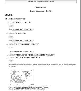
5. INSPECT FAN AND GENERATOR V BELT
HINT:
As the belt tensioner coordinates belt tension automatically by its mechanism, you do not need to adjust it
by yourself.
Fig. 1: Identifying Indicator Mark On Automatic Tensioner
Courtesy of TOYOTA MOTOR SALES, U.S.A., INC.
2007 Lexus GX 470
2007 ENGINE Engine Mechanical - GX 470
2007 Lexus GX 470
2007 ENGINE Engine Mechanical - GX 470
Microsoft
Sunday, August 23, 2009 8:03:02 AM Page 1 © 2005 Mitchell Repair Information Company, LLC.
Microsoft
Sunday, August 23, 2009 8:03:11 AM Page 1 © 2005 Mitchell Repair Information Company, LLC.
2. a. Check that the indicator mark on the automatic tensioner is within the A range.
b. When the mark is out of the standard range, replace the V belt with a new one.
6. INSPECT V-RIBBED BELT TENSIONER ASSEMBLY (See INSPECTION )
7. WARM UP ENGINE
8. INSPECT IGNITION TIMING
a. When using the intelligent tester or OBD II scan tool:
Fig. 2: Connecting Intelligent Tester To DLC3
Courtesy of TOYOTA MOTOR SALES, U.S.A., INC.
1. Connect the intelligent tester or OBD II scan tool to the DLC3.
HINT:
Refer to the intelligent tester or OBD II scan tool operator's manual for further details.
Ignition timing:
5 to 15° BTDC at idle (Transmission in neutral)
2. Disconnect the intelligent tester or OBD II scan tool from the DLC3.
b. When not using the intelligent tester or OBD II scan tool:
1. Remove the V-bank cover.
2007 Lexus GX 470
2007 ENGINE Engine Mechanical - GX 470
Microsoft
Sunday, August 23, 2009 8:03:03 AM Page 2 © 2005 Mitchell Repair Information Company, LLC.
3. Fig. 3: Identifying Ignition Coil Connector
Courtesy of TOYOTA MOTOR SALES, U.S.A., INC.
2. Connect the tester probe of a timing light to the wire of the ignition coil connector for the No.
1 cylinder.
Fig. 4: Connecting Tachometer Probe To Terminal TAC Of DLC3 Using SST
Courtesy of TOYOTA MOTOR SALES, U.S.A., INC.
3. Using SST, connect the tachometer probe to terminal TAC of the DLC3.
SST 09843-18030
Fig. 5: Connecting Terminals TC & CG Of DLC3 Using SST
Courtesy of TOYOTA MOTOR SALES, U.S.A., INC.
4. Using SST, connect terminals TC and CG of the DLC3.
SST 09843-18040
2007 Lexus GX 470
2007 ENGINE Engine Mechanical - GX 470
Microsoft
Sunday, August 23, 2009 8:03:03 AM Page 3 © 2005 Mitchell Repair Information Company, LLC.
4. Fig. 6: Checking Ignition Timing Using Timing Belt
Courtesy of TOYOTA MOTOR SALES, U.S.A., INC.
5. Using the timing light, check the ignition timing.
Ignition timing:
5 to 15° BTDC at idle (Transmission in neutral)
6. Remove the SST from the DLC3.
7. Disconnect the timing light from the engine.
8. Install the V-bank cover.
9. INSPECT ENGINE IDLE SPEED
a. When using the intelligent tester or OBD II scan tool:
Fig. 7: Connecting Intelligent Tester To DLC3
Courtesy of TOYOTA MOTOR SALES, U.S.A., INC.
1. Connect the intelligent tester or OBD II scan tool to the DLC3.
HINT:
Refer to the intelligent tester or OBD II scan tool operator's manual for further details.
2. Run the engine at 2,500 rpm for approx. 90 seconds.
2007 Lexus GX 470
2007 ENGINE Engine Mechanical - GX 470
Microsoft
Sunday, August 23, 2009 8:03:03 AM Page 4 © 2005 Mitchell Repair Information Company, LLC.
5. 3. Check the idle speed.
Idle speed:
700 +- 50 rpm
If the idle speed is not as specified, check the air intake system.
4. Disconnect the intelligent tester or OBD II scan tool from the DLC3.
b. When not using the intelligent tester or OBD II scan tool:
Fig. 8: Connecting Tachometer Probe To Terminal TAC Of DLC3 Using SST
Courtesy of TOYOTA MOTOR SALES, U.S.A., INC.
1. Using SST, connect the tachometer probe to terminal TAC of the DLC3.
SST 09843-18030
HINT:
Refer to the intelligent tester operator's manual for further details.
2. Run the engine at 2,500 rpm for approx. 90 seconds.
3. Check the idle speed.
Idle speed:
700 +- 50 rpm
4. Remove the SST from the DLC3.
5. Disconnect the tachometer from the DLC3.
10. INSPECT COMPRESSION
a. Remove the V-bank cover sub-assembly.
b. Remove the air cleaner hose assembly.
2007 Lexus GX 470
2007 ENGINE Engine Mechanical - GX 470
Microsoft
Sunday, August 23, 2009 8:03:03 AM Page 5 © 2005 Mitchell Repair Information Company, LLC.
6. c. Disconnect the throttle control motor connector.
d. Remove the 8 ignition coils.
e. Remove the 8 spark plugs.
f. Disconnect the 8 injector connectors.
g. Inspect the cylinder compression pressure.
Fig. 9: Measuring Compression Pressure Of Cylinder
Courtesy of TOYOTA MOTOR SALES, U.S.A., INC.
1. Insert a compression gauge into the spark plug hole (Procedure "A").
2. Fully open the throttle forcibly by hand.
3. While cranking the engine, measure the compression pressure (Procedure "B").
HINT:
Always use a fully charged battery to obtain an engine speed of 250 rpm or more.
4. Repeat procedures "A" to "B" for each cylinder.
5. If the cylinder compression in one or more cylinders is low, pour a small amount of engine
NOTE: This measurement must be done as quickly as possible.
Compression pressure:
1,373 kPa (14.0 kgf/cm2 , 199 psi) or more
Minimum pressure:
1,030 kPa (10.5 kgf/cm2 , 149 psi)
Difference between each cylinder:
98 kPa (1.0 kgf/cm2 , 14 psi) or less
2007 Lexus GX 470
2007 ENGINE Engine Mechanical - GX 470
Microsoft
Sunday, August 23, 2009 8:03:03 AM Page 6 © 2005 Mitchell Repair Information Company, LLC.
7. oil into the cylinder through the spark plug hole and repeat procedures "A" to "B" for the
cylinders with low compression.
If adding oil helps the compression, the piston rings and/or cylinder bore may be worn
or damaged.
If pressure stays low, a valve may be sticking, seating is improper, or there may be
leakage past the gasket.
h. Connect the 8 injector connectors.
i. Install the 8 spark plugs.
j. Install the 8 ignition coils.
k. Connect the throttle control motor connector.
l. Install the air cleaner hose assembly.
m. Install the V-bank cover sub-assembly.
11. INSPECT CO/HC
HINT:
This check is used only to determine whether or not the idle CO/HC complies with regulations.
a. Start the engine.
b. Sustain the engine speed at 2,500 rpm for approx. 180 seconds.
Fig. 10: Inserting CO/HC Meter Testing Probe
Courtesy of TOYOTA MOTOR SALES, U.S.A., INC.
c. Insert the CO/HC meter testing probe at least 40 cm (1.3 ft) into the tailpipe during idling.
d. Immediately check CO/HC concentration at idle and/or 2,500 rpm.
HINT:
When performing the 2 mode (2,500 rpm and idle) test, follow the measurement order prescribed
by the applicable local regulations.
If the CO/HC concentration does not comply with the regulations, troubleshoot in the order given
below.
2007 Lexus GX 470
2007 ENGINE Engine Mechanical - GX 470
Microsoft
Sunday, August 23, 2009 8:03:03 AM Page 7 © 2005 Mitchell Repair Information Company, LLC.
8. 1. Check the heated oxygen sensor operation (See DTC P0136 OXYGEN SENSOR
CIRCUIT MALFUNCTION (BANK 1 SENSOR 2) and DTC P2195 OXYGEN (A/F)
SENSOR SIGNAL STUCK LEAN (BANK 1 SENSOR 1) ).
2. See the table below for possible causes, then inspect and correct the applicable causes if
necessary.
PROBLEM SYMPTOM TABLE
DRIVE BELT
COMPONENTS
CO HC Symptom Cause
Normal High Rough idle
1. Faulty ignitions:
Incorrect timing
Fouled, shorted or improperly
gapped plugs
2. Incorrect valve clearance
3. Leaky intake and exhaust valves
4. Leaky cylinder
Low High
Rough idle (Fluctuating HC
reading)
1. Vacuum leaks:
PCV hose
Intake manifold
Throttle body
2. Lean mixture causing misfire
High High
Rough idle Black smoke from
exhaust)
1. Restricted air filter
2. Faulty SFI system:
Faulty pressure regulator
Defective ECT sensor
Faulty ECM
Faulty injector
Faulty throttle position sensor
Faulty MAF sensor
2007 Lexus GX 470
2007 ENGINE Engine Mechanical - GX 470
Microsoft
Sunday, August 23, 2009 8:03:03 AM Page 8 © 2005 Mitchell Repair Information Company, LLC.
9. Fig. 11: Identifying Drive Belt Replacement Components
Courtesy of TOYOTA MOTOR SALES, U.S.A., INC.
REMOVAL
1. REMOVE FAN AND GENERATOR V BELT
2007 Lexus GX 470
2007 ENGINE Engine Mechanical - GX 470
Microsoft
Sunday, August 23, 2009 8:03:03 AM Page 9 © 2005 Mitchell Repair Information Company, LLC.
10. Fig. 12: Loosening Belt Tension
Courtesy of TOYOTA MOTOR SALES, U.S.A., INC.
a. Loosen the belt tension by turning the belt tensioner counterclockwise, and then remove the fan and
generator V belt.
HINT:
The pulley bolt for the belt tensioner has left-hand thread.
INSPECTION
1. INSPECT V-RIBBED BELT TENSIONER ASSEMBLY
a. Remove the V belt from the tensioner pulley. Then check that nothing gets caught the tensioner by
turning it clockwise and counterclockwise.
b. When a malfunction exists, replace the tensioner.
INSTALLATION
1. INSTALL FAN AND GENERATOR V BELT
Fig. 13: Identifying V Belt Position
Courtesy of TOYOTA MOTOR SALES, U.S.A., INC.
a. Set the V belt onto every parts except the No. 2 idler pulley.
b. Loosen the V belt by turning the belt tensioner counterclockwise.
2007 Lexus GX 470
2007 ENGINE Engine Mechanical - GX 470
Microsoft
Sunday, August 23, 2009 8:03:03 AM Page 10 © 2005 Mitchell Repair Information Company, LLC.
11. c. Set the V belt to the No. 2 idler pulley.
Fig. 14: Identifying Indicator Mark On Automatic Tensioner
Courtesy of TOYOTA MOTOR SALES, U.S.A., INC.
d. After installing a new belt, check that the mark is within the B range.
VALVE CLEARANCE
ADJUSTMENT
1. DRAIN ENGINE COOLANT (See REPLACEMENT )
2. SEPARATE BATTERY NEGATIVE TERMINAL
3. REMOVE V-BANK COVER SUB-ASSEMBLY
4. REMOVE ENGINE ROOM COVER SIDE
5. REMOVE ENGINE ROOM SIDE COVER LH
6. REMOVE AIR CLEANER HOSE ASSEMBLY
7. REMOVE RADIATOR SUPPORT SEAL UPPER
8. REMOVE FAN AND GENERATOR V BELT (See REMOVAL )
9. REMOVE OIL COOLER PIPE (See REMOVAL )
10. REMOVE IGNITION COIL ASSEMBLY
11. REMOVE NO. 3 TIMING BELT COVER SUB-ASSEMBLY LH (See REMOVAL )
12. REMOVE NO. 2 TIMING CHAIN OR BELT COVER (See REMOVAL )
13. REMOVE CYLINDER HEAD COVER SUB-ASSEMBLY
a. Remove the 9 bolts, 9 seal washers and cylinder head cover.
14. REMOVE CYLINDER HEAD COVER SUB-ASSEMBLY LH
a. Disconnect the PCV hose.
b. Remove the 9 bolts, 9 seal washers and cylinder head cover.
15. SET NO. 1 CYLINDER TO TDC/COMPRESSION
2007 Lexus GX 470
2007 ENGINE Engine Mechanical - GX 470
Microsoft
Sunday, August 23, 2009 8:03:03 AM Page 11 © 2005 Mitchell Repair Information Company, LLC.
12. Thank you very much for
your reading. Please Click
Here. Then Get COMPLETE
MANUAL. NO WAITING
NOTE:
If there is no response to
click on the link above,
please download the PDF
document first and then
click on it.
13. Fig. 15: Turning Crankshaft Pulley
Courtesy of TOYOTA MOTOR SALES, U.S.A., INC.
a. Turn the crankshaft pulley to align its notch with timing mark "0" of the No. 1 timing belt cover.
Fig. 16: Identifying Timing Marks Of Camshaft Timing Pulleys & Timing Belt Rear Plates
Courtesy of TOYOTA MOTOR SALES, U.S.A., INC.
b. Check that the timing marks of the camshaft timing pulleys and timing belt rear plates are aligned.
If not, turn the crankshaft 1 complete revolution (360°) and align the marks as above.
16. INSPECT VALVE CLEARANCE
2007 Lexus GX 470
2007 ENGINE Engine Mechanical - GX 470
Microsoft
Sunday, August 23, 2009 8:03:03 AM Page 12 © 2005 Mitchell Repair Information Company, LLC.
14. Fig. 17: Measuring Clearance Between Valve Lifter & Camshaft Using Feeler Gauge
Courtesy of TOYOTA MOTOR SALES, U.S.A., INC.
a. Check only the valves indicated.
1. Using a feeler gauge, measure the clearance between the valve lifter and camshaft.
2. Record the out-of-specification valve clearance measurements. They will be used later to
determine the required replacement adjusting shim.
Valve clearance (Cold):
Intake:
0.15 to 0.25 mm (0.006 to 0.010 in.)
Exhaust:
0.25 to 0.35 mm (0.010 to 0.014 in.)
b. Turn the crankshaft 1 complete revolution (360°) and align the camshaft timing marks.
c. Check only the valves. Measure the valve clearance.
17. ADJUST VALVE CLEARANCE
2007 Lexus GX 470
2007 ENGINE Engine Mechanical - GX 470
Microsoft
Sunday, August 23, 2009 8:03:03 AM Page 13 © 2005 Mitchell Repair Information Company, LLC.
15. Fig. 18: Measuring Clearance Between Valve Lifter & Camshaft
Courtesy of TOYOTA MOTOR SALES, U.S.A., INC.
a. Remove the timing belt (See REMOVAL ).
b. Remove the camshafts (RH Bank) (See REMOVAL ).
c. Remove the camshafts (LH Bank) (See REMOVAL ).
d. Remove the valve lifter and adjusting shim.
e. Determine the replacement adjusting shim size according to the formula or tables.
Fig. 19: Measuring Thickness Of Removed Shim Using Micrometer
Courtesy of TOYOTA MOTOR SALES, U.S.A., INC.
1. Using a micrometer, measure the thickness of the removed shim.
NOTE: Be careful not to drop the adjusting shim into the cylinder head.
2007 Lexus GX 470
2007 ENGINE Engine Mechanical - GX 470
Microsoft
Sunday, August 23, 2009 8:03:03 AM Page 14 © 2005 Mitchell Repair Information Company, LLC.