SlideShare a Scribd company logo
1 of 17
Download to read offline
IN00U–36
N17080
Filler Cap
Float
Reservoir
A Grommet
Clip
Slotted Spring Pin
: Specified torque
A Non–reusable part
Cylinder
Piston
Push Rod
Washer
Snap Ring
Boot
A Gasket
Lock Nut
Clevis Pin
Clevis
N·m (kgf·cm, ft·lbf)
12 (120, 9)
15 (155, 11)
–INTRODUCTION HOW TO USE THIS MANUAL
IN–1
1AuthorĂ: DateĂ:
2003 TOYOTA TUNDRA (RM956U)
HOW TO USE THIS MANUAL
GENERAL INFORMATION
1. INDEX
An INDEX is provided on the first page of each section to guide you to the item to be repaired. To assist you
in finding your way through the manual, the section title and major heading are given at the top of every page.
2. PRECAUTION
At the beginning of each section, a PRECAUTION is given that pertains to all repair operations contained
in that section.
Read these precautions before starting any repair task.
3. TROUBLESHOOTING
TROUBLESHOOTING tables are included for each system to help you diagnose the problem and find the
cause. The fundamentals of how to proceed with troubleshooting are described on page IN–17.
Be sure to read this before performing troubleshooting.
4. PREPARATION
Preparation lists the SST (Special Service Tools), recommended tools, equipment, lubricant and SSM (Spe-
cial Service Materials) which should be prepared before beginning the operation and explains the purpose
of each one.
5. REPAIR PROCEDURES
Most repair operations begin with an overview illustration. It identifies the components and shows how the
parts fit together.
Example:
Illustration:
what to do and where
21. CHECK PISTON STROKE OF OVERDRIVE BRAKE
(a)
Task heading : what to do
SST 09350–30020 (09350–06120)
Set part No. Component part No.
Detailed text : how to do task
(b)
Piston stroke: 1.40 Ċ 1.70 mm (0.0551 Ċ 0.0669 in.)
Specification
Place SST and a dial indicator onto the overdrive brake pis-
ton as shown in the illustration.
Measure the stroke applying and releasing the compressed
air (392 Ċ 785 kPa, 4 Ċ 8 kgf/cm2 or 57 Ċ 114 psi) as shown
in the illustration.
IN–2
–INTRODUCTION HOW TO USE THIS MANUAL
2AuthorĂ: DateĂ:
2003 TOYOTA TUNDRA (RM956U)
The procedures are presented in a step–by–step format:
Y The illustration shows what to do and where to do it.
Y The task heading tells what to do.
Y The detailed text tells how to perform the task and gives other information such as specifications
and warnings.
Example:
This format provides the experienced technician with a FAST TRACK to the information needed. The upper
case task heading can be read at a glance when necessary, and the text below it provides detailed informa-
tion. Important specifications and warnings always stand out in bold type.
6. REFERENCES
References have been kept to a minimum. However, when they are required you are given the page to refer
to.
7. SPECIFICATIONS
Specifications are presented in bold type throughout the text where needed. You never have to leave the
procedure to look up your specifications. They are also found in Service Specifications section for quick ref-
erence.
8. CAUTIONS, NOTICES, HINTS:
Y CAUTIONS are presented in bold type, and indicate there is a possibility of injury to you or other
people.
Y NOTICES are also presented in bold type, and indicate the possibility of damage to the components
being repaired.
Y HINTS are separated from the text but do not appear in bold. They provide additional information to
help you perform the repair efficiently.
9. SI UNIT
The UNITS given in this manual are primarily expressed according to the SI UNIT (International System of
Unit), and alternately expressed in the metric system and in the English System.
Example:
Torque: 30 N·m (310 kgf·cm, 22 ft·lbf)
IN01P–04
B02417
A
B
B02418
5VZ–FE Engine
2UZ–FE Engine
–INTRODUCTION IDENTIFICATION INFORMATION
IN–3
3AuthorĂ: DateĂ:
2003 TOYOTA TUNDRA (RM956U)
IDENTIFICATION INFORMATION
VEHICLE IDENTIFICATION AND
ENGINE SERIAL NUMBER
1. VEHICLE IDENTIFICATION NUMBER
The vehicle identification number is stamped on the vehicle
identification number plate and certification label.
A: Vehicle Identification Number Plate
B: Certification Label
2. ENGINE SERIAL NUMBER
The engine serial number is stamped on the engine block, as
shown in the illustration.
IN0CO–12
FI1066
Z11554
Seal Lock Adhesive
IN–4
–INTRODUCTION REPAIR INSTRUCTIONS
4AuthorĂ: DateĂ:
2003 TOYOTA TUNDRA (RM956U)
REPAIR INSTRUCTIONS
GENERAL INFORMATION
BASIC REPAIR HINT
(a) Use fender, seat and floor covers to keep the vehicle
clean and prevent damage.
(b) During disassembly, keep parts in the appropriate order
to facilitate reassembly.
(c) Installation and removal of battery terminal:
(1) Before performing electrical work, disconnect the
negative (–) terminal cable from the battery.
(2) If it is necessary to disconnect the battery for in-
spection or repair, first disconnect the negative (–)
terminal cable.
(3) When disconnecting the terminal cable, to prevent
damage to battery terminal, loosen the cable nut
and raise the cable straight up without twisting or
prying it.
(4) Clean the battery terminals and cable ends with a
clean shop rag. Do not scrape them with a file or oth-
er abrasive objects.
(5) Install the cable ends to the battery terminals after
loosening the nut, and tighten the nut after installa-
tion. Do not use a hammer to tap the cable ends
onto the terminals.
(6) Be sure the cover for the positive (+) terminal is
properly in place.
(d) Check hose and wiring connectors to make sure that they
are connected securely and correctly.
(e) Non–reusable parts
(1) Always replace cotter pins, gaskets, O–rings, oil
seals, etc. with new ones.
(2) Non–reusable parts are indicated in the component
illustrations by the ” ” symbol.
(f) Precoated parts
Precoated parts are bolts, nuts, etc. that are coated with
a seal lock adhesive at the factory.
(1) If a precoated part is retightened, loosened or
caused to move in any way, it must be recoated with
the specified adhesive.
(2) When reusing precoated parts, clean off the old
adhesive and dry with compressed air. Then apply
the specified seal lock adhesive to the bolt, nut or
threads.
BE1367
Medium Current Fuse and High Current Fuse
Equal Amperage Rating
V00076
AbbreviationPart NameSymbolIllustration
FUSE
MEDIUM CURRENT FUSE
HIGH CURRENT FUSE
FUSIBLE LINK
CIRCUIT BREAKER
FUSE
M–FUSE
H–FUSE
FL
CB
–INTRODUCTION REPAIR INSTRUCTIONS
IN–5
5AuthorĂ: DateĂ:
2003 TOYOTA TUNDRA (RM956U)
(3) Precoated parts are indicated in the component il-
lustrations by the ”Y” symbol.
(g) When necessary, use a sealer on gaskets to prevent
leaks.
(h) Carefully observe all specifications for bolt tightening
torques. Always use a torque wrench.
(i) Use of special service tools (SST) and special service ma-
terials (SSM) may be required, depending on the nature
of the repair. Be sure to use SST and SSM where speci-
fied and follow the proper work procedure. A list of SST
and SSM can be found in Preparation section in this
manual.
(j) When replacing fuses, be sure the new fuse has the cor-
rect amperage rating. DO NOT exceed the rating or use
one with a lower rating.
IN0253
WRONG CORRECT
IN0252
WRONG CORRECT
IN–6
–INTRODUCTION REPAIR INSTRUCTIONS
6AuthorĂ: DateĂ:
2003 TOYOTA TUNDRA (RM956U)
(k) Care must be taken when jacking up and supporting the
vehicle. Be sure to lift and support the vehicle at the prop-
er locations (See page IN–8).
A Cancel the parking brake on the level place and
shift the transmission in Neutral (or N position).
A When jacking up the front wheels of the vehicle at
first place stoppers behind the rear wheels.
A When jacking up the rear wheels of the vehicle at
first place stoppers before the front wheels.
A When either the front or rear wheels only should be
jacked up, set rigid racks and place stoppers in front
and behind the other wheels on the ground.
A After the vehicle is jacked up, be sure to support it
on rigid racks . It is extremely dangerous to do any
work on a vehicle raised on a jack alone, even for
a small job that can be finished quickly.
(l) Observe the following precautions to avoid damage to the
following parts:
(1) Do not open the cover or case of the ECU unless
absolutely necessary. (If the IC terminals are
touched, the IC may be destroyed by static electric-
ity.)
(2) To disconnect vacuum hoses, pull off the end, not
the middle of the hose.
(3) To pull apart electrical connectors, pull on the con-
nector itself, not the wires.
(4) Be careful not to drop electrical components, such
as sensors or relays. If they are dropped on a hard
floor, they should be replaced and not reused.
(5) When steam cleaning an engine, protect the elec-
tronic components, air filter and emission–related
components from water.
(6) Never use an impact wrench to remove or install
temperature switches or temperature sensors.
IN0002
Example
–INTRODUCTION REPAIR INSTRUCTIONS
IN–7
7AuthorĂ: DateĂ:
2003 TOYOTA TUNDRA (RM956U)
(7) When checking continuity at the wire connector, in-
sert the tester probe carefully to prevent terminals
from bending.
(8) When using a vacuum gauge, never force the hose
onto a connector that is too large. Use a step–down
adapter for adjustment. Once the hose has been
stretched, it may leak air.
(m) Installation and removal of vacuum hose:
(1) When disconnecting vacuum hoses, use tags to
identify how they should be reconnected to.
(2) After completing a job, double check that the vacu-
um hoses are properly connected. A label under the
hood shows the proper layout.
(n) Unless otherwise stated, all resistance is measured at an
ambient temperature of 20°C (68°F). Because the resis-
tance may be outside specifications if measured at high
temperatures immediately after the vehicle has been run-
ning, measurement should be made when the engine has
cooled down.
IN0DY–01
B07972
JACK POSITION A A A A A A A A A A A A A A A A A A
Front A A A A A A A A A Center of crossmember
Rear A A A A A A A A A Center of rear axle housing
SUPPORT POSITION
Safety stand A A A A A A A A A A A A A A A A
Front
IN–8
–INTRODUCTION REPAIR INSTRUCTIONS
8AuthorĂ: DateĂ:
2003 TOYOTA TUNDRA (RM956U)
VEHICLE LIFT AND SUPPORT LOCATIONS
IN0DB–04
BO4111
Negative Cable
–INTRODUCTION FOR ALL OF VEHICLES
IN–9
9AuthorĂ: DateĂ:
2003 TOYOTA TUNDRA (RM956U)
FOR ALL OF VEHICLES
PRECAUTION
1. FOR VEHICLES EQUIPPED WITH SRS AIRBAG AND
SEAT BELT PRETENSIONER
(a) The TOYOTA TUNDRA is equipped with an SRS (Sup-
plemental Restraint System), such as the driver airbag,
front passenger airbag assembly and seat belt preten-
sioner.
Failure to carry out service operations in the correct se-
quence could cause the supplemental restraint system to
unexpectedly deploy during servicing, possibly leading to
a serious accident.
Further, if a mistake is made in servicing the supplemental
restraint system, it is possible the SRS may fail to operate
when required. Before servicing (including removal or
installation of parts, inspection or replacement), be sure
to read the following items carefully, then follow the cor-
rect procedure described in this manual.
(b) GENERAL NOTICE
(1) Malfunction symptoms of the supplemental re-
straint system are difficult to confirm, so the diag-
nostic trouble codes become the most important
source of information when troubleshooting. When
troubleshooting the supplemental restraint system,
always inspect the diagnostic trouble codes before
disconnecting the battery (See page DI–490).
(2) Work must be started after 90 seconds from the
time the ignition switch is turned to the ”LOCK” posi-
tion and the negative (–) terminal cable is discon-
nected from the battery.
(The supplemental restraint system is equipped
with a back–up power source so that if work is
started within 90 seconds of disconnecting the neg-
ative (–) terminal cable from the battery, the SRS
may deploy.)
When the negative (–) terminal cable is discon-
nected from the battery, memory of the clock and
audio systems will be cancelled. So before starting
work, make a record of the contents memorized by
the each memory system. Then when work is fin-
ished, reset the clock and audio systems as before.
To avoid erasing the memory of each memory sys-
tem, never use a back–up power supply from anoth-
er battery.
F04784
Mark
IN–10
–INTRODUCTION FOR ALL OF VEHICLES
10AuthorĂ: DateĂ:
2003 TOYOTA TUNDRA (RM956U)
(3) Even in cases of a minor collision where the SRS
does not deploy, the steering wheel pad (See page
RS–12), front passenger airbag assembly (See
page RS–26) and seat belt pretensioner (See page
BO–140) should be inspected.
(4) Never use SRS parts from another vehicle. When
replacing parts, replace them with new parts.
(5) Before repairs, remove the airbag sensor if shocks
are likely to be applied to the sensor during repairs.
(6) Never disassemble and repair the airbag sensor as-
sembly, steering wheel pad, front passenger airbag
assembly or seat belt pretensioner.
(7) If the airbag sensor assembly, steering wheel pad,
front passenger airbag assembly or seat belt pre-
tensioner has been dropped, or if there are cracks,
dents or other defects in the case, bracket or con-
nector, replace them with new ones.
(8) Do not directly expose the airbag sensor assembly,
steering wheel pad, front passenger airbag assem-
bly or seat belt pretensioner to hot air or flames.
(9) Use a volt/ohmmeter with high impedance (10 kΩ/V
minimum) for troubleshooting of the electrical cir-
cuit.
(10) Information labels are attached to the periphery of
the SRS components. Follow the instructions on the
notices.
(11) After work on the supplemental restraint system is
completed, check the SRS warning light (See page
DI–490).
(c) SPIRAL CABLE (in Combination Switch)
The steering wheel must be fitted correctly to the steering
column with the spiral cable at the neutral position, other-
wise cable disconnection and other troubles may result.
Refer to SR–28 concerning correct steering wheel instal-
lation.
F14450 B13595
Example:
CORRECT WRONG
Z13950
Example:
–INTRODUCTION FOR ALL OF VEHICLES
IN–11
11AuthorĂ: DateĂ:
2003 TOYOTA TUNDRA (RM956U)
(d) STEERING WHEEL PAD (with Airbag)
(1) When removing the steering wheel pad or handling
a new steering wheel pad, it should be placed with
the pad top surface facing up.
Storing the pad with its metallic surface upward may
lead to a serious accident if the airbag inflates for
some reason. In addition do not store a steering
wheel pad on top of another one.
(2) Never measure the resistance of the airbag squib.
(This may cause the airbag to deploy, which is very
dangerous.)
(3) Grease should not be applied to the steering wheel
pad and the pad should not be cleaned with deter-
gents of any kind.
(4) Store the steering wheel pad where the ambient
temperature remains below 93°C (200°F), without
high humidity and away from electrical noise.
(5) When using electric welding, first disconnect the air-
bag connector (yellow color and 2 pins) under the
steering column near the combination switch con-
nector before starting work.
(6) When disposing of a vehicle or the steering wheel
pad alone, the airbag should be deployed using an
SST before disposal (See page RS–14).
Perform the operation in a safe place away from
electrical noise.
B02416
Example:
CORRECT WRONG
Z13951
Example:
IN–12
–INTRODUCTION FOR ALL OF VEHICLES
12AuthorĂ: DateĂ:
2003 TOYOTA TUNDRA (RM956U)
(e) FRONT PASSENGER AIRBAG ASSEMBLY
(1) Always store a removed or new front passenger air-
bag assembly with the airbag deployment direction
facing up.
Storing the airbag assembly with the airbag deploy-
ment direction facing down could cause a serious
accident if the airbag deploys.
(2) Never measure the resistance of the airbag squib.
(This may cause the airbag to deploy, which is very
dangerous.)
(3) Grease should not be applied to the front passen-
ger airbag assembly and the airbag door should not
be cleaned with detergents of any kind.
(4) Store the airbag assembly where the ambient tem-
perature remains below 93°C (200°F), without high
humidity and away from electrical noise.
(5) When using electric welding, first disconnect the air-
bag connector (yellow color and 2 pins) installed on
assembly before starting work.
(6) When disposing of a vehicle or the airbag assembly
alone, the airbag should be deployed using an SST
before disposal (See page RS–27).
Perform the operation in a safe place away from
electrical noise.
Thank you very much for
your reading. Please Click
Here. Then Get COMPLETE
MANUAL. NO WAITING
NOTE:
If there is no response to
click on the link above,
please download the PDF
document first and then
click on it.
B02121
Example:
–INTRODUCTION FOR ALL OF VEHICLES
IN–13
13AuthorĂ: DateĂ:
2003 TOYOTA TUNDRA (RM956U)
(f) SEAT BELT PRETENSIONER
(1) Never measure the resistance of the seat belt pre-
tensioner. (This may cause the seat belt pretension-
er activation which is very dangerous.)
(2) Never disassemble the seat belt pretensioner.
(3) Never install the seat belt pretensioner in another
vehicle.
(4) Store the seat belt pretensioner where the ambient
temperature remains below 80°C (176°F) and
away from electrical noise without high humidity.
(5) When using electric welding, first disconnect the
connector (yellow color and 2 pins) before starting
work.
(6) When disposing of a vehicle or the seat belt preten-
sioner alone, the seat belt pretensioner should be
activated before disposal (See page BO–142). Per-
form the operation in a safe place away from electri-
cal noise.
(7) The seat belt pretensioner is hot after activation, so
let it cool down sufficiently before the disposal.
However never apply water to the seat belt preten-
sioner.
IN–14
–INTRODUCTION FOR ALL OF VEHICLES
14AuthorĂ: DateĂ:
2003 TOYOTA TUNDRA (RM956U)
(g) AIRBAG SENSOR ASSEMBLY
(1) Never reuse the airbag sensor assembly involved
in a collision when the SRS has deployed.
(2) The connectors to the airbag sensor assembly
should be connected or disconnected with the sen-
sor mounted on the floor. If the connectors are con-
nected or disconnected while the airbag sensor as-
sembly is not mounted to the floor, it could cause
undesired ignition of the supplemental restraint sys-
tem.
(3) Work must be started after 90 seconds from the
time the ignition switch is turned to the ”LOCK” posi-
tion and the negative (–) terminal cable is discon-
nected from the battery, even if only loosening the
set bolts of the airbag sensor assembly.
(h) WIRE HARNESS AND CONNECTOR
The SRS wire harness is integrated with the cowl wire har-
ness assembly and floor wire harness assembly. All the
connectors for the system are also a standard yellow col-
or. If the SRS wire harness becomes disconnected or the
connector becomes broken due to an accident, etc., re-
pair or replace it.
–INTRODUCTION FOR ALL OF VEHICLES
IN–15
15AuthorĂ: DateĂ:
2003 TOYOTA TUNDRA (RM956U)
2. FOR VEHICLES EQUIPPED WITH A CATALYTIC CONVERTER
CAUTION:
If large amount of unburned gasoline flows into the converter, it may overheat and create a fire haz-
ard. To prevent this, observe the following precautions and explain them to your customer.
(a) Use only unleaded gasoline.
(b) Avoid prolonged idling.
Avoid running the engine at idle speed for more than 20 minutes.
(c) Avoid spark jump test.
(1) Perform spark jump test only when absolutely necessary. Perform this test as rapidly as possible.
(2) While testing, never race the engine.
(d) Avoid prolonged engine compression measurement.
Engine compression tests must be done as rapidly as possible.
(e) Do not run engine when fuel tank is nearly empty.
This may cause the engine to misfire and create an extra load on the converter.
(f) Avoid coasting with ignition turned off.
(g) Do not dispose of used catalyst along with parts contaminated with gasoline or oil.
3. IF VEHICLE IS EQUIPPED WITH MOBILE COMMUNICATION SYSTEM
For vehicles with mobile communication systems such as two–way radios and cellular telephones, observe
the following precautions.
(1) Install the antenna as far as possible away from the ECU and sensors of the vehicle’s electronic
system.
(2) Install the antenna feeder at least 20 cm (7.87 in.) away from the ECU and sensors of the ve-
hicle’s electronic systems. For details about ECU and sensors locations, refer to the section on
the applicable component.
(3) Do not wind the antenna feeder together with the other wiring as much as possible, also avoid
running the antenna feeder parallel with other wire harness.
(4) Check that the antenna and feeder are correctly adjusted.
(5) Do not install powerful mobile communications system.
4. FOR USING OBD II SCAN TOOL OR TOYOTA HAND–HELD TESTER
CAUTION:
Observe the following for safety reasons:
Y Before using the OBD II scan tool or TOYOTA hand–held tester, the OBD II scan tool’s instruc-
tion book or TOYOTA hand–held tester’s operator manual should be read thoroughly.
Y Be sure to route all cables securely when driving with the OBD II scan tool or TOYOTA hand–
held tester connected to the vehicle. (i.e. Keep cables away from feet, pedals, steering wheel
and shift lever.)
Y Two persons are required when test driving with the OBD II scan tool or TOYOTA hand–held
tester, one person to drive the vehicle and one person to operate the OBD II scan tool or TOYO-
TA hand–held tester.
IN01T–12
IN–16 –INTRODUCTION HOW TO TROUBLESHOOT ECU CONTROLLED
SYSTEMS
16AuthorĂ: DateĂ:
2003 TOYOTA TUNDRA (RM956U)
HOW TO TROUBLESHOOT ECU CONTROLLED SYSTEMS
GENERAL INFORMATION
A large number of ECU controlled systems are used in the TOYOTA TUNDRA. In general, the ECU con-
trolled system is considered to be a very intricate system requiring a high level of technical knowledge and
expert skill to troubleshoot. However, the fact is that if you proceed to inspect the circuits one by one, trouble-
shooting of these systems is not complex. If you have adequate understanding of the system and a basic
knowledge of electricity, accurate diagnosis and necessary repair can be performed to locate and fix the
problem. This manual is designed through emphasis of the above standpoint to help service technicians
perform accurate and effective troubleshooting, and is compiled for the following major ECU controlled sys-
tems:
The troubleshooting procedure and how to make use of it are described on the following pages.
System Page
1. Engine (5VZ–FE) DI–1
2. Engine (2UZ–FE) DI–192
3. Automatic Transmission (A340E, A340F) DI–382
4. Anti–Lock Brake System DI–446
5. Supplemental Restraint System DI–488
6. TOYOTA Vehicle Intrusion Protection System DI–592
7. Cruise Control System (5VZ–FE) DI–638
8. Cruise Control System (2UZ–FE) DI–662
FOR USING OBD II SCAN TOOL OR HAND–HELD TESTER
Y Before using the scan tool or tester, the scan tool’s instruction book or tester’s operator manual should
be read thoroughly.
Y If the scan tool or tester cannot communicate with ECU controlled systems when you have connected
the cable of the scan tool or tester to DLC3, turned the ignition switch ON and operated the scan tool,
there is a problem on the vehicle side or tool side.
(1) If communication is normal when the tool is connected to another vehicle, inspect the diagnosis
data link line (Bustline) or ECU power circuit of the vehicle.
(2) If communication is still not possible when the tool is connected to another vehicle, the problem
is probably in the tool itself, so perform the Self Test procedures outline in the Tester Operator’s
Manual.

More Related Content

What's hot

Toyota 42 6 fg18 forklift service repair manual
Toyota 42 6 fg18 forklift service repair manualToyota 42 6 fg18 forklift service repair manual
Toyota 42 6 fg18 forklift service repair manualfjjskkdmnsme
 
авеnsis-supplementchassisbody2000-rm781
авеnsis-supplementchassisbody2000-rm781авеnsis-supplementchassisbody2000-rm781
авеnsis-supplementchassisbody2000-rm781gsx1
 
Toyota 42-5fg20 Forklift Service Repair Manual
Toyota 42-5fg20 Forklift Service Repair ManualToyota 42-5fg20 Forklift Service Repair Manual
Toyota 42-5fg20 Forklift Service Repair Manualfudufjjskekkmdm
 
MITSUBISHI FG50CN FORKLIFT TRUCKS Service Repair Manual SN: EF25D-80001-UP
MITSUBISHI FG50CN FORKLIFT TRUCKS Service Repair Manual SN: EF25D-80001-UPMITSUBISHI FG50CN FORKLIFT TRUCKS Service Repair Manual SN: EF25D-80001-UP
MITSUBISHI FG50CN FORKLIFT TRUCKS Service Repair Manual SN: EF25D-80001-UPjksemd jksemm
 
Toyota 42-5fg15 Forklift Service Repair Manual
Toyota 42-5fg15 Forklift Service Repair ManualToyota 42-5fg15 Forklift Service Repair Manual
Toyota 42-5fg15 Forklift Service Repair Manualfujdfjjksekdmm
 
Toyota 02 5 fd40 forklift service repair manual
Toyota 02 5 fd40 forklift service repair manualToyota 02 5 fd40 forklift service repair manual
Toyota 02 5 fd40 forklift service repair manualhhjsekmdmm
 
YAMAHA 60FEDO OUTBOARD Service Repair Manual L: 407212 -
YAMAHA 60FEDO OUTBOARD Service Repair Manual L: 407212 -YAMAHA 60FEDO OUTBOARD Service Repair Manual L: 407212 -
YAMAHA 60FEDO OUTBOARD Service Repair Manual L: 407212 -jhsefnn kjsfem
 
Toyota 5FD70 Forklift Service Repair Manual
Toyota 5FD70 Forklift Service Repair ManualToyota 5FD70 Forklift Service Repair Manual
Toyota 5FD70 Forklift Service Repair Manualjkseodlpled
 
Toyota 02-5fd15 Forklift Service Repair Manual
Toyota 02-5fd15 Forklift Service Repair ManualToyota 02-5fd15 Forklift Service Repair Manual
Toyota 02-5fd15 Forklift Service Repair Manualfjjkskefkmem
 
Toyota 02 5fd30 forklift service repair manual
Toyota 02 5fd30 forklift service repair manualToyota 02 5fd30 forklift service repair manual
Toyota 02 5fd30 forklift service repair manualfjsjjekdkme
 
Yamaha outboard l225 feto, l225tr service repair manual u 200132
Yamaha outboard l225 feto, l225tr service repair manual u 200132  Yamaha outboard l225 feto, l225tr service repair manual u 200132
Yamaha outboard l225 feto, l225tr service repair manual u 200132 fujsefkskemm
 
1994 Yamaha Viking VK 540 Series Snowmobile Service Repair Manual
1994 Yamaha Viking VK 540 Series Snowmobile Service Repair Manual1994 Yamaha Viking VK 540 Series Snowmobile Service Repair Manual
1994 Yamaha Viking VK 540 Series Snowmobile Service Repair Manualjkksemd yeuyhd
 

What's hot (12)

Toyota 42 6 fg18 forklift service repair manual
Toyota 42 6 fg18 forklift service repair manualToyota 42 6 fg18 forklift service repair manual
Toyota 42 6 fg18 forklift service repair manual
 
авеnsis-supplementchassisbody2000-rm781
авеnsis-supplementchassisbody2000-rm781авеnsis-supplementchassisbody2000-rm781
авеnsis-supplementchassisbody2000-rm781
 
Toyota 42-5fg20 Forklift Service Repair Manual
Toyota 42-5fg20 Forklift Service Repair ManualToyota 42-5fg20 Forklift Service Repair Manual
Toyota 42-5fg20 Forklift Service Repair Manual
 
MITSUBISHI FG50CN FORKLIFT TRUCKS Service Repair Manual SN: EF25D-80001-UP
MITSUBISHI FG50CN FORKLIFT TRUCKS Service Repair Manual SN: EF25D-80001-UPMITSUBISHI FG50CN FORKLIFT TRUCKS Service Repair Manual SN: EF25D-80001-UP
MITSUBISHI FG50CN FORKLIFT TRUCKS Service Repair Manual SN: EF25D-80001-UP
 
Toyota 42-5fg15 Forklift Service Repair Manual
Toyota 42-5fg15 Forklift Service Repair ManualToyota 42-5fg15 Forklift Service Repair Manual
Toyota 42-5fg15 Forklift Service Repair Manual
 
Toyota 02 5 fd40 forklift service repair manual
Toyota 02 5 fd40 forklift service repair manualToyota 02 5 fd40 forklift service repair manual
Toyota 02 5 fd40 forklift service repair manual
 
YAMAHA 60FEDO OUTBOARD Service Repair Manual L: 407212 -
YAMAHA 60FEDO OUTBOARD Service Repair Manual L: 407212 -YAMAHA 60FEDO OUTBOARD Service Repair Manual L: 407212 -
YAMAHA 60FEDO OUTBOARD Service Repair Manual L: 407212 -
 
Toyota 5FD70 Forklift Service Repair Manual
Toyota 5FD70 Forklift Service Repair ManualToyota 5FD70 Forklift Service Repair Manual
Toyota 5FD70 Forklift Service Repair Manual
 
Toyota 02-5fd15 Forklift Service Repair Manual
Toyota 02-5fd15 Forklift Service Repair ManualToyota 02-5fd15 Forklift Service Repair Manual
Toyota 02-5fd15 Forklift Service Repair Manual
 
Toyota 02 5fd30 forklift service repair manual
Toyota 02 5fd30 forklift service repair manualToyota 02 5fd30 forklift service repair manual
Toyota 02 5fd30 forklift service repair manual
 
Yamaha outboard l225 feto, l225tr service repair manual u 200132
Yamaha outboard l225 feto, l225tr service repair manual u 200132  Yamaha outboard l225 feto, l225tr service repair manual u 200132
Yamaha outboard l225 feto, l225tr service repair manual u 200132
 
1994 Yamaha Viking VK 540 Series Snowmobile Service Repair Manual
1994 Yamaha Viking VK 540 Series Snowmobile Service Repair Manual1994 Yamaha Viking VK 540 Series Snowmobile Service Repair Manual
1994 Yamaha Viking VK 540 Series Snowmobile Service Repair Manual
 

Similar to 2003 toyota tundra service repair manual

1996 TOYOTA T100 Factory Service Manual
1996 TOYOTA T100 Factory Service Manual 1996 TOYOTA T100 Factory Service Manual
1996 TOYOTA T100 Factory Service Manual OBD Codex
 
2006 TOYOTA HIGHLANDER Service Repair Manual
2006 TOYOTA HIGHLANDER Service Repair Manual2006 TOYOTA HIGHLANDER Service Repair Manual
2006 TOYOTA HIGHLANDER Service Repair Manualfudfjjskekfmem
 
2002 toyota highlander service repair manual
2002 toyota highlander service repair manual2002 toyota highlander service repair manual
2002 toyota highlander service repair manualdfjjsjekfkskemme
 
2003 toyota highlander service repair manual
2003 toyota highlander service repair manual2003 toyota highlander service repair manual
2003 toyota highlander service repair manualfjjsjeusekkekm
 
2007 toyota highlander service repair manual
2007 toyota highlander service repair manual2007 toyota highlander service repair manual
2007 toyota highlander service repair manualfujjsekfkksekm
 
2007 toyota highlander service repair manual
2007 toyota highlander service repair manual2007 toyota highlander service repair manual
2007 toyota highlander service repair manualfjjsieskekfmmse
 
2001 toyota highlander service repair manual
2001 toyota highlander service repair manual2001 toyota highlander service repair manual
2001 toyota highlander service repair manualfhsjejkdm
 
аvensisenginetransmission2005
аvensisenginetransmission2005аvensisenginetransmission2005
аvensisenginetransmission2005gsx1
 
2006 toyota sienna service repair manual
2006 toyota sienna service repair manual2006 toyota sienna service repair manual
2006 toyota sienna service repair manualfjjskkemsmee
 
Toyota 5FD70 Forklift Service Repair Manual
Toyota 5FD70 Forklift Service Repair ManualToyota 5FD70 Forklift Service Repair Manual
Toyota 5FD70 Forklift Service Repair Manualdfujdjfjkskekmd
 
Toyota 7FGCSU20 Forklift Service Repair Manual
Toyota 7FGCSU20 Forklift Service Repair ManualToyota 7FGCSU20 Forklift Service Repair Manual
Toyota 7FGCSU20 Forklift Service Repair Manualjkksemd yeuyhd
 
Toyota 7 fgcsu20 forklift service repair manual
Toyota 7 fgcsu20 forklift service repair manualToyota 7 fgcsu20 forklift service repair manual
Toyota 7 fgcsu20 forklift service repair manualfjskekazswdmme
 
Toyota 7 fgcu15 forklift service repair manual
Toyota 7 fgcu15 forklift service repair manualToyota 7 fgcu15 forklift service repair manual
Toyota 7 fgcu15 forklift service repair manualfhhsjdkmem
 
Toyota 7 fgcu18 forklift service repair manual
Toyota 7 fgcu18 forklift service repair manualToyota 7 fgcu18 forklift service repair manual
Toyota 7 fgcu18 forklift service repair manualjfjskekdhnejd
 
Toyota 5 fg60 forklift service repair manual
Toyota 5 fg60 forklift service repair manualToyota 5 fg60 forklift service repair manual
Toyota 5 fg60 forklift service repair manualjsemm fvdcf
 
Toyota 5FD60 Forklift Service Repair Manual
Toyota 5FD60 Forklift Service Repair ManualToyota 5FD60 Forklift Service Repair Manual
Toyota 5FD60 Forklift Service Repair Manualukjkme kjdmfkm
 
Toyota 5FDM70 Forklift Service Repair Manual
Toyota 5FDM70 Forklift Service Repair ManualToyota 5FDM70 Forklift Service Repair Manual
Toyota 5FDM70 Forklift Service Repair Manualukjemm kjskmfm
 
2003 toyota corolla service repair manual
2003 toyota corolla service repair manual2003 toyota corolla service repair manual
2003 toyota corolla service repair manualfhsjejkdm
 
2008 toyota corolla service repair manual
2008 toyota corolla service repair manual2008 toyota corolla service repair manual
2008 toyota corolla service repair manualfjjsieskekfmmse
 

Similar to 2003 toyota tundra service repair manual (20)

1996 TOYOTA T100 Factory Service Manual
1996 TOYOTA T100 Factory Service Manual 1996 TOYOTA T100 Factory Service Manual
1996 TOYOTA T100 Factory Service Manual
 
2006 TOYOTA HIGHLANDER Service Repair Manual
2006 TOYOTA HIGHLANDER Service Repair Manual2006 TOYOTA HIGHLANDER Service Repair Manual
2006 TOYOTA HIGHLANDER Service Repair Manual
 
2002 toyota highlander service repair manual
2002 toyota highlander service repair manual2002 toyota highlander service repair manual
2002 toyota highlander service repair manual
 
2003 toyota highlander service repair manual
2003 toyota highlander service repair manual2003 toyota highlander service repair manual
2003 toyota highlander service repair manual
 
2007 toyota highlander service repair manual
2007 toyota highlander service repair manual2007 toyota highlander service repair manual
2007 toyota highlander service repair manual
 
2007 toyota highlander service repair manual
2007 toyota highlander service repair manual2007 toyota highlander service repair manual
2007 toyota highlander service repair manual
 
2001 toyota highlander service repair manual
2001 toyota highlander service repair manual2001 toyota highlander service repair manual
2001 toyota highlander service repair manual
 
Introduction
IntroductionIntroduction
Introduction
 
аvensisenginetransmission2005
аvensisenginetransmission2005аvensisenginetransmission2005
аvensisenginetransmission2005
 
2006 toyota sienna service repair manual
2006 toyota sienna service repair manual2006 toyota sienna service repair manual
2006 toyota sienna service repair manual
 
Toyota 5FD70 Forklift Service Repair Manual
Toyota 5FD70 Forklift Service Repair ManualToyota 5FD70 Forklift Service Repair Manual
Toyota 5FD70 Forklift Service Repair Manual
 
Toyota 7FGCSU20 Forklift Service Repair Manual
Toyota 7FGCSU20 Forklift Service Repair ManualToyota 7FGCSU20 Forklift Service Repair Manual
Toyota 7FGCSU20 Forklift Service Repair Manual
 
Toyota 7 fgcsu20 forklift service repair manual
Toyota 7 fgcsu20 forklift service repair manualToyota 7 fgcsu20 forklift service repair manual
Toyota 7 fgcsu20 forklift service repair manual
 
Toyota 7 fgcu15 forklift service repair manual
Toyota 7 fgcu15 forklift service repair manualToyota 7 fgcu15 forklift service repair manual
Toyota 7 fgcu15 forklift service repair manual
 
Toyota 7 fgcu18 forklift service repair manual
Toyota 7 fgcu18 forklift service repair manualToyota 7 fgcu18 forklift service repair manual
Toyota 7 fgcu18 forklift service repair manual
 
Toyota 5 fg60 forklift service repair manual
Toyota 5 fg60 forklift service repair manualToyota 5 fg60 forklift service repair manual
Toyota 5 fg60 forklift service repair manual
 
Toyota 5FD60 Forklift Service Repair Manual
Toyota 5FD60 Forklift Service Repair ManualToyota 5FD60 Forklift Service Repair Manual
Toyota 5FD60 Forklift Service Repair Manual
 
Toyota 5FDM70 Forklift Service Repair Manual
Toyota 5FDM70 Forklift Service Repair ManualToyota 5FDM70 Forklift Service Repair Manual
Toyota 5FDM70 Forklift Service Repair Manual
 
2003 toyota corolla service repair manual
2003 toyota corolla service repair manual2003 toyota corolla service repair manual
2003 toyota corolla service repair manual
 
2008 toyota corolla service repair manual
2008 toyota corolla service repair manual2008 toyota corolla service repair manual
2008 toyota corolla service repair manual
 

More from fujjsekfkksekm

2007 polaris 600 ho switchback snowmobile service repair manual
2007 polaris 600 ho switchback snowmobile service repair manual2007 polaris 600 ho switchback snowmobile service repair manual
2007 polaris 600 ho switchback snowmobile service repair manualfujjsekfkksekm
 
2007 lexus gs300 gs430 s190 service repair manual
2007 lexus gs300 gs430 s190 service repair manual2007 lexus gs300 gs430 s190 service repair manual
2007 lexus gs300 gs430 s190 service repair manualfujjsekfkksekm
 
2006 saturn vue service repair manual
2006 saturn vue service repair manual2006 saturn vue service repair manual
2006 saturn vue service repair manualfujjsekfkksekm
 
2006 kawasaki ex650 a6f service repair manual
2006 kawasaki ex650 a6f service repair manual2006 kawasaki ex650 a6f service repair manual
2006 kawasaki ex650 a6f service repair manualfujjsekfkksekm
 
2005 toyota celica service repair manual
2005 toyota celica service repair manual2005 toyota celica service repair manual
2005 toyota celica service repair manualfujjsekfkksekm
 
2005 honda trx500 tm fourtrax foreman service repair manual
2005 honda trx500 tm fourtrax foreman service repair manual2005 honda trx500 tm fourtrax foreman service repair manual
2005 honda trx500 tm fourtrax foreman service repair manualfujjsekfkksekm
 
2004 nissan frontier service repair manual
2004 nissan frontier service repair manual2004 nissan frontier service repair manual
2004 nissan frontier service repair manualfujjsekfkksekm
 
2003 nissan frontier service repair manual
2003 nissan frontier service repair manual2003 nissan frontier service repair manual
2003 nissan frontier service repair manualfujjsekfkksekm
 
2002 lexus gx470 service repair manual
2002 lexus gx470 service repair manual2002 lexus gx470 service repair manual
2002 lexus gx470 service repair manualfujjsekfkksekm
 
2000 iveco daily 3 service repair manual
2000 iveco daily 3 service repair manual2000 iveco daily 3 service repair manual
2000 iveco daily 3 service repair manualfujjsekfkksekm
 
1998 toyota corolla service repair manual
1998 toyota corolla service repair manual1998 toyota corolla service repair manual
1998 toyota corolla service repair manualfujjsekfkksekm
 
1997 toyota avalon service repair manual
1997 toyota avalon service repair manual1997 toyota avalon service repair manual
1997 toyota avalon service repair manualfujjsekfkksekm
 
1996 polaris indy storm sks snowmobile service repair manual
1996 polaris indy storm sks snowmobile service repair manual1996 polaris indy storm sks snowmobile service repair manual
1996 polaris indy storm sks snowmobile service repair manualfujjsekfkksekm
 
1992 yamaha vmx1200 d v max service repair manual
1992 yamaha vmx1200 d v max service repair manual1992 yamaha vmx1200 d v max service repair manual
1992 yamaha vmx1200 d v max service repair manualfujjsekfkksekm
 
1988 polaris sprint snowmobile service repair manual
1988 polaris sprint snowmobile service repair manual1988 polaris sprint snowmobile service repair manual
1988 polaris sprint snowmobile service repair manualfujjsekfkksekm
 
Kubota st alpha-35 tractor service repair manual
Kubota st alpha-35 tractor service repair manualKubota st alpha-35 tractor service repair manual
Kubota st alpha-35 tractor service repair manualfujjsekfkksekm
 
Kubota rck72 f36 front cut ride on mower service repair manual
Kubota rck72 f36 front cut ride on mower service repair manualKubota rck72 f36 front cut ride on mower service repair manual
Kubota rck72 f36 front cut ride on mower service repair manualfujjsekfkksekm
 
Kubota gr2100 ec lawnmower service repair manual
Kubota gr2100 ec lawnmower service repair manualKubota gr2100 ec lawnmower service repair manual
Kubota gr2100 ec lawnmower service repair manualfujjsekfkksekm
 
Kubota gr1600 ec2 ride on mower service repair manual
Kubota gr1600 ec2 ride on mower service repair manualKubota gr1600 ec2 ride on mower service repair manual
Kubota gr1600 ec2 ride on mower service repair manualfujjsekfkksekm
 
Steyr profi cvt 4130 tractor service repair manual
Steyr profi cvt 4130 tractor service repair manualSteyr profi cvt 4130 tractor service repair manual
Steyr profi cvt 4130 tractor service repair manualfujjsekfkksekm
 

More from fujjsekfkksekm (20)

2007 polaris 600 ho switchback snowmobile service repair manual
2007 polaris 600 ho switchback snowmobile service repair manual2007 polaris 600 ho switchback snowmobile service repair manual
2007 polaris 600 ho switchback snowmobile service repair manual
 
2007 lexus gs300 gs430 s190 service repair manual
2007 lexus gs300 gs430 s190 service repair manual2007 lexus gs300 gs430 s190 service repair manual
2007 lexus gs300 gs430 s190 service repair manual
 
2006 saturn vue service repair manual
2006 saturn vue service repair manual2006 saturn vue service repair manual
2006 saturn vue service repair manual
 
2006 kawasaki ex650 a6f service repair manual
2006 kawasaki ex650 a6f service repair manual2006 kawasaki ex650 a6f service repair manual
2006 kawasaki ex650 a6f service repair manual
 
2005 toyota celica service repair manual
2005 toyota celica service repair manual2005 toyota celica service repair manual
2005 toyota celica service repair manual
 
2005 honda trx500 tm fourtrax foreman service repair manual
2005 honda trx500 tm fourtrax foreman service repair manual2005 honda trx500 tm fourtrax foreman service repair manual
2005 honda trx500 tm fourtrax foreman service repair manual
 
2004 nissan frontier service repair manual
2004 nissan frontier service repair manual2004 nissan frontier service repair manual
2004 nissan frontier service repair manual
 
2003 nissan frontier service repair manual
2003 nissan frontier service repair manual2003 nissan frontier service repair manual
2003 nissan frontier service repair manual
 
2002 lexus gx470 service repair manual
2002 lexus gx470 service repair manual2002 lexus gx470 service repair manual
2002 lexus gx470 service repair manual
 
2000 iveco daily 3 service repair manual
2000 iveco daily 3 service repair manual2000 iveco daily 3 service repair manual
2000 iveco daily 3 service repair manual
 
1998 toyota corolla service repair manual
1998 toyota corolla service repair manual1998 toyota corolla service repair manual
1998 toyota corolla service repair manual
 
1997 toyota avalon service repair manual
1997 toyota avalon service repair manual1997 toyota avalon service repair manual
1997 toyota avalon service repair manual
 
1996 polaris indy storm sks snowmobile service repair manual
1996 polaris indy storm sks snowmobile service repair manual1996 polaris indy storm sks snowmobile service repair manual
1996 polaris indy storm sks snowmobile service repair manual
 
1992 yamaha vmx1200 d v max service repair manual
1992 yamaha vmx1200 d v max service repair manual1992 yamaha vmx1200 d v max service repair manual
1992 yamaha vmx1200 d v max service repair manual
 
1988 polaris sprint snowmobile service repair manual
1988 polaris sprint snowmobile service repair manual1988 polaris sprint snowmobile service repair manual
1988 polaris sprint snowmobile service repair manual
 
Kubota st alpha-35 tractor service repair manual
Kubota st alpha-35 tractor service repair manualKubota st alpha-35 tractor service repair manual
Kubota st alpha-35 tractor service repair manual
 
Kubota rck72 f36 front cut ride on mower service repair manual
Kubota rck72 f36 front cut ride on mower service repair manualKubota rck72 f36 front cut ride on mower service repair manual
Kubota rck72 f36 front cut ride on mower service repair manual
 
Kubota gr2100 ec lawnmower service repair manual
Kubota gr2100 ec lawnmower service repair manualKubota gr2100 ec lawnmower service repair manual
Kubota gr2100 ec lawnmower service repair manual
 
Kubota gr1600 ec2 ride on mower service repair manual
Kubota gr1600 ec2 ride on mower service repair manualKubota gr1600 ec2 ride on mower service repair manual
Kubota gr1600 ec2 ride on mower service repair manual
 
Steyr profi cvt 4130 tractor service repair manual
Steyr profi cvt 4130 tractor service repair manualSteyr profi cvt 4130 tractor service repair manual
Steyr profi cvt 4130 tractor service repair manual
 

Recently uploaded

Call Girls in Malviya Nagar Delhi 💯 Call Us 🔝9205541914 🔝( Delhi) Escorts Ser...
Call Girls in Malviya Nagar Delhi 💯 Call Us 🔝9205541914 🔝( Delhi) Escorts Ser...Call Girls in Malviya Nagar Delhi 💯 Call Us 🔝9205541914 🔝( Delhi) Escorts Ser...
Call Girls in Malviya Nagar Delhi 💯 Call Us 🔝9205541914 🔝( Delhi) Escorts Ser...Delhi Call girls
 
Bangalore Call Girls: 🍓 7737669865 🍓 High Profile Model Escorts | Bangalore E...
Bangalore Call Girls: 🍓 7737669865 🍓 High Profile Model Escorts | Bangalore E...Bangalore Call Girls: 🍓 7737669865 🍓 High Profile Model Escorts | Bangalore E...
Bangalore Call Girls: 🍓 7737669865 🍓 High Profile Model Escorts | Bangalore E...amitlee9823
 
如何办理麦考瑞大学毕业证(MQU毕业证书)成绩单原版一比一
如何办理麦考瑞大学毕业证(MQU毕业证书)成绩单原版一比一如何办理麦考瑞大学毕业证(MQU毕业证书)成绩单原版一比一
如何办理麦考瑞大学毕业证(MQU毕业证书)成绩单原版一比一ozave
 
Dubai Call Girls R0yalty O525547819 Call Girls Dubai
Dubai Call Girls R0yalty O525547819 Call Girls DubaiDubai Call Girls R0yalty O525547819 Call Girls Dubai
Dubai Call Girls R0yalty O525547819 Call Girls Dubaikojalkojal131
 
John Deere Tractors 6130M 6140M Diagnostic Manual
John Deere Tractors  6130M 6140M Diagnostic ManualJohn Deere Tractors  6130M 6140M Diagnostic Manual
John Deere Tractors 6130M 6140M Diagnostic ManualExcavator
 
Lecture-20 Kleene’s Theorem-1.pptx best for understanding the automata
Lecture-20 Kleene’s Theorem-1.pptx best for understanding the automataLecture-20 Kleene’s Theorem-1.pptx best for understanding the automata
Lecture-20 Kleene’s Theorem-1.pptx best for understanding the automataHUSNAINAHMAD39
 
Call Girls Kanakapura Road Just Call 👗 7737669865 👗 Top Class Call Girl Servi...
Call Girls Kanakapura Road Just Call 👗 7737669865 👗 Top Class Call Girl Servi...Call Girls Kanakapura Road Just Call 👗 7737669865 👗 Top Class Call Girl Servi...
Call Girls Kanakapura Road Just Call 👗 7737669865 👗 Top Class Call Girl Servi...amitlee9823
 
一比一原版(PU学位证书)普渡大学毕业证学历认证加急办理
一比一原版(PU学位证书)普渡大学毕业证学历认证加急办理一比一原版(PU学位证书)普渡大学毕业证学历认证加急办理
一比一原版(PU学位证书)普渡大学毕业证学历认证加急办理ezgenuh
 
Top Rated Call Girls South Mumbai : 9920725232 We offer Beautiful and sexy Ca...
Top Rated Call Girls South Mumbai : 9920725232 We offer Beautiful and sexy Ca...Top Rated Call Girls South Mumbai : 9920725232 We offer Beautiful and sexy Ca...
Top Rated Call Girls South Mumbai : 9920725232 We offer Beautiful and sexy Ca...amitlee9823
 
What Does The Engine Malfunction Reduced Power Message Mean For Your BMW X5
What Does The Engine Malfunction Reduced Power Message Mean For Your BMW X5What Does The Engine Malfunction Reduced Power Message Mean For Your BMW X5
What Does The Engine Malfunction Reduced Power Message Mean For Your BMW X5Bavarian Workshop
 
Escorts Service Rajajinagar ☎ 7737669865☎ Book Your One night Stand (Bangalore)
Escorts Service Rajajinagar ☎ 7737669865☎ Book Your One night Stand (Bangalore)Escorts Service Rajajinagar ☎ 7737669865☎ Book Your One night Stand (Bangalore)
Escorts Service Rajajinagar ☎ 7737669865☎ Book Your One night Stand (Bangalore)amitlee9823
 
What Causes BMW Chassis Stabilization Malfunction Warning To Appear
What Causes BMW Chassis Stabilization Malfunction Warning To AppearWhat Causes BMW Chassis Stabilization Malfunction Warning To Appear
What Causes BMW Chassis Stabilization Malfunction Warning To AppearJCL Automotive
 
Vip Mumbai Call Girls Navi Mumbai Call On 9920725232 With Body to body massag...
Vip Mumbai Call Girls Navi Mumbai Call On 9920725232 With Body to body massag...Vip Mumbai Call Girls Navi Mumbai Call On 9920725232 With Body to body massag...
Vip Mumbai Call Girls Navi Mumbai Call On 9920725232 With Body to body massag...amitlee9823
 
Majestic Call Girls: 🍓 7737669865 🍓 High Profile Model Escorts | Bangalore Es...
Majestic Call Girls: 🍓 7737669865 🍓 High Profile Model Escorts | Bangalore Es...Majestic Call Girls: 🍓 7737669865 🍓 High Profile Model Escorts | Bangalore Es...
Majestic Call Girls: 🍓 7737669865 🍓 High Profile Model Escorts | Bangalore Es...amitlee9823
 
ENJOY Call Girls In Okhla Vihar Delhi Call 9654467111
ENJOY Call Girls In Okhla Vihar Delhi Call 9654467111ENJOY Call Girls In Okhla Vihar Delhi Call 9654467111
ENJOY Call Girls In Okhla Vihar Delhi Call 9654467111Sapana Sha
 
Top Rated Call Girls Mumbai Central : 9920725232 We offer Beautiful and sexy ...
Top Rated Call Girls Mumbai Central : 9920725232 We offer Beautiful and sexy ...Top Rated Call Girls Mumbai Central : 9920725232 We offer Beautiful and sexy ...
Top Rated Call Girls Mumbai Central : 9920725232 We offer Beautiful and sexy ...amitlee9823
 
Tata_Nexon_brochure tata nexon brochure tata
Tata_Nexon_brochure tata nexon brochure tataTata_Nexon_brochure tata nexon brochure tata
Tata_Nexon_brochure tata nexon brochure tataaritradey27234
 
What Could Cause Your Subaru's Touch Screen To Stop Working
What Could Cause Your Subaru's Touch Screen To Stop WorkingWhat Could Cause Your Subaru's Touch Screen To Stop Working
What Could Cause Your Subaru's Touch Screen To Stop WorkingBruce Cox Imports
 

Recently uploaded (20)

Call Girls in Malviya Nagar Delhi 💯 Call Us 🔝9205541914 🔝( Delhi) Escorts Ser...
Call Girls in Malviya Nagar Delhi 💯 Call Us 🔝9205541914 🔝( Delhi) Escorts Ser...Call Girls in Malviya Nagar Delhi 💯 Call Us 🔝9205541914 🔝( Delhi) Escorts Ser...
Call Girls in Malviya Nagar Delhi 💯 Call Us 🔝9205541914 🔝( Delhi) Escorts Ser...
 
Bangalore Call Girls: 🍓 7737669865 🍓 High Profile Model Escorts | Bangalore E...
Bangalore Call Girls: 🍓 7737669865 🍓 High Profile Model Escorts | Bangalore E...Bangalore Call Girls: 🍓 7737669865 🍓 High Profile Model Escorts | Bangalore E...
Bangalore Call Girls: 🍓 7737669865 🍓 High Profile Model Escorts | Bangalore E...
 
如何办理麦考瑞大学毕业证(MQU毕业证书)成绩单原版一比一
如何办理麦考瑞大学毕业证(MQU毕业证书)成绩单原版一比一如何办理麦考瑞大学毕业证(MQU毕业证书)成绩单原版一比一
如何办理麦考瑞大学毕业证(MQU毕业证书)成绩单原版一比一
 
Dubai Call Girls R0yalty O525547819 Call Girls Dubai
Dubai Call Girls R0yalty O525547819 Call Girls DubaiDubai Call Girls R0yalty O525547819 Call Girls Dubai
Dubai Call Girls R0yalty O525547819 Call Girls Dubai
 
John Deere Tractors 6130M 6140M Diagnostic Manual
John Deere Tractors  6130M 6140M Diagnostic ManualJohn Deere Tractors  6130M 6140M Diagnostic Manual
John Deere Tractors 6130M 6140M Diagnostic Manual
 
Lecture-20 Kleene’s Theorem-1.pptx best for understanding the automata
Lecture-20 Kleene’s Theorem-1.pptx best for understanding the automataLecture-20 Kleene’s Theorem-1.pptx best for understanding the automata
Lecture-20 Kleene’s Theorem-1.pptx best for understanding the automata
 
Call Girls Kanakapura Road Just Call 👗 7737669865 👗 Top Class Call Girl Servi...
Call Girls Kanakapura Road Just Call 👗 7737669865 👗 Top Class Call Girl Servi...Call Girls Kanakapura Road Just Call 👗 7737669865 👗 Top Class Call Girl Servi...
Call Girls Kanakapura Road Just Call 👗 7737669865 👗 Top Class Call Girl Servi...
 
一比一原版(PU学位证书)普渡大学毕业证学历认证加急办理
一比一原版(PU学位证书)普渡大学毕业证学历认证加急办理一比一原版(PU学位证书)普渡大学毕业证学历认证加急办理
一比一原版(PU学位证书)普渡大学毕业证学历认证加急办理
 
Top Rated Call Girls South Mumbai : 9920725232 We offer Beautiful and sexy Ca...
Top Rated Call Girls South Mumbai : 9920725232 We offer Beautiful and sexy Ca...Top Rated Call Girls South Mumbai : 9920725232 We offer Beautiful and sexy Ca...
Top Rated Call Girls South Mumbai : 9920725232 We offer Beautiful and sexy Ca...
 
What Does The Engine Malfunction Reduced Power Message Mean For Your BMW X5
What Does The Engine Malfunction Reduced Power Message Mean For Your BMW X5What Does The Engine Malfunction Reduced Power Message Mean For Your BMW X5
What Does The Engine Malfunction Reduced Power Message Mean For Your BMW X5
 
Escorts Service Rajajinagar ☎ 7737669865☎ Book Your One night Stand (Bangalore)
Escorts Service Rajajinagar ☎ 7737669865☎ Book Your One night Stand (Bangalore)Escorts Service Rajajinagar ☎ 7737669865☎ Book Your One night Stand (Bangalore)
Escorts Service Rajajinagar ☎ 7737669865☎ Book Your One night Stand (Bangalore)
 
What Causes BMW Chassis Stabilization Malfunction Warning To Appear
What Causes BMW Chassis Stabilization Malfunction Warning To AppearWhat Causes BMW Chassis Stabilization Malfunction Warning To Appear
What Causes BMW Chassis Stabilization Malfunction Warning To Appear
 
(INDIRA) Call Girl Nashik Call Now 8617697112 Nashik Escorts 24x7
(INDIRA) Call Girl Nashik Call Now 8617697112 Nashik Escorts 24x7(INDIRA) Call Girl Nashik Call Now 8617697112 Nashik Escorts 24x7
(INDIRA) Call Girl Nashik Call Now 8617697112 Nashik Escorts 24x7
 
Vip Mumbai Call Girls Navi Mumbai Call On 9920725232 With Body to body massag...
Vip Mumbai Call Girls Navi Mumbai Call On 9920725232 With Body to body massag...Vip Mumbai Call Girls Navi Mumbai Call On 9920725232 With Body to body massag...
Vip Mumbai Call Girls Navi Mumbai Call On 9920725232 With Body to body massag...
 
Majestic Call Girls: 🍓 7737669865 🍓 High Profile Model Escorts | Bangalore Es...
Majestic Call Girls: 🍓 7737669865 🍓 High Profile Model Escorts | Bangalore Es...Majestic Call Girls: 🍓 7737669865 🍓 High Profile Model Escorts | Bangalore Es...
Majestic Call Girls: 🍓 7737669865 🍓 High Profile Model Escorts | Bangalore Es...
 
ENJOY Call Girls In Okhla Vihar Delhi Call 9654467111
ENJOY Call Girls In Okhla Vihar Delhi Call 9654467111ENJOY Call Girls In Okhla Vihar Delhi Call 9654467111
ENJOY Call Girls In Okhla Vihar Delhi Call 9654467111
 
(INDIRA) Call Girl Surat Call Now 8250077686 Surat Escorts 24x7
(INDIRA) Call Girl Surat Call Now 8250077686 Surat Escorts 24x7(INDIRA) Call Girl Surat Call Now 8250077686 Surat Escorts 24x7
(INDIRA) Call Girl Surat Call Now 8250077686 Surat Escorts 24x7
 
Top Rated Call Girls Mumbai Central : 9920725232 We offer Beautiful and sexy ...
Top Rated Call Girls Mumbai Central : 9920725232 We offer Beautiful and sexy ...Top Rated Call Girls Mumbai Central : 9920725232 We offer Beautiful and sexy ...
Top Rated Call Girls Mumbai Central : 9920725232 We offer Beautiful and sexy ...
 
Tata_Nexon_brochure tata nexon brochure tata
Tata_Nexon_brochure tata nexon brochure tataTata_Nexon_brochure tata nexon brochure tata
Tata_Nexon_brochure tata nexon brochure tata
 
What Could Cause Your Subaru's Touch Screen To Stop Working
What Could Cause Your Subaru's Touch Screen To Stop WorkingWhat Could Cause Your Subaru's Touch Screen To Stop Working
What Could Cause Your Subaru's Touch Screen To Stop Working
 

2003 toyota tundra service repair manual

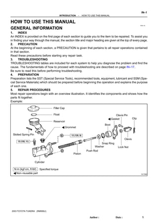
  • 1. IN00U–36 N17080 Filler Cap Float Reservoir A Grommet Clip Slotted Spring Pin : Specified torque A Non–reusable part Cylinder Piston Push Rod Washer Snap Ring Boot A Gasket Lock Nut Clevis Pin Clevis N·m (kgf·cm, ft·lbf) 12 (120, 9) 15 (155, 11) –INTRODUCTION HOW TO USE THIS MANUAL IN–1 1AuthorĂ: DateĂ: 2003 TOYOTA TUNDRA (RM956U) HOW TO USE THIS MANUAL GENERAL INFORMATION 1. INDEX An INDEX is provided on the first page of each section to guide you to the item to be repaired. To assist you in finding your way through the manual, the section title and major heading are given at the top of every page. 2. PRECAUTION At the beginning of each section, a PRECAUTION is given that pertains to all repair operations contained in that section. Read these precautions before starting any repair task. 3. TROUBLESHOOTING TROUBLESHOOTING tables are included for each system to help you diagnose the problem and find the cause. The fundamentals of how to proceed with troubleshooting are described on page IN–17. Be sure to read this before performing troubleshooting. 4. PREPARATION Preparation lists the SST (Special Service Tools), recommended tools, equipment, lubricant and SSM (Spe- cial Service Materials) which should be prepared before beginning the operation and explains the purpose of each one. 5. REPAIR PROCEDURES Most repair operations begin with an overview illustration. It identifies the components and shows how the parts fit together. Example:
  • 2. Illustration: what to do and where 21. CHECK PISTON STROKE OF OVERDRIVE BRAKE (a) Task heading : what to do SST 09350–30020 (09350–06120) Set part No. Component part No. Detailed text : how to do task (b) Piston stroke: 1.40 Ċ 1.70 mm (0.0551 Ċ 0.0669 in.) Specification Place SST and a dial indicator onto the overdrive brake pis- ton as shown in the illustration. Measure the stroke applying and releasing the compressed air (392 Ċ 785 kPa, 4 Ċ 8 kgf/cm2 or 57 Ċ 114 psi) as shown in the illustration. IN–2 –INTRODUCTION HOW TO USE THIS MANUAL 2AuthorĂ: DateĂ: 2003 TOYOTA TUNDRA (RM956U) The procedures are presented in a step–by–step format: Y The illustration shows what to do and where to do it. Y The task heading tells what to do. Y The detailed text tells how to perform the task and gives other information such as specifications and warnings. Example: This format provides the experienced technician with a FAST TRACK to the information needed. The upper case task heading can be read at a glance when necessary, and the text below it provides detailed informa- tion. Important specifications and warnings always stand out in bold type. 6. REFERENCES References have been kept to a minimum. However, when they are required you are given the page to refer to. 7. SPECIFICATIONS Specifications are presented in bold type throughout the text where needed. You never have to leave the procedure to look up your specifications. They are also found in Service Specifications section for quick ref- erence. 8. CAUTIONS, NOTICES, HINTS: Y CAUTIONS are presented in bold type, and indicate there is a possibility of injury to you or other people. Y NOTICES are also presented in bold type, and indicate the possibility of damage to the components being repaired. Y HINTS are separated from the text but do not appear in bold. They provide additional information to help you perform the repair efficiently. 9. SI UNIT The UNITS given in this manual are primarily expressed according to the SI UNIT (International System of Unit), and alternately expressed in the metric system and in the English System. Example: Torque: 30 N·m (310 kgf·cm, 22 ft·lbf)
  • 3. IN01P–04 B02417 A B B02418 5VZ–FE Engine 2UZ–FE Engine –INTRODUCTION IDENTIFICATION INFORMATION IN–3 3AuthorĂ: DateĂ: 2003 TOYOTA TUNDRA (RM956U) IDENTIFICATION INFORMATION VEHICLE IDENTIFICATION AND ENGINE SERIAL NUMBER 1. VEHICLE IDENTIFICATION NUMBER The vehicle identification number is stamped on the vehicle identification number plate and certification label. A: Vehicle Identification Number Plate B: Certification Label 2. ENGINE SERIAL NUMBER The engine serial number is stamped on the engine block, as shown in the illustration.
  • 4. IN0CO–12 FI1066 Z11554 Seal Lock Adhesive IN–4 –INTRODUCTION REPAIR INSTRUCTIONS 4AuthorĂ: DateĂ: 2003 TOYOTA TUNDRA (RM956U) REPAIR INSTRUCTIONS GENERAL INFORMATION BASIC REPAIR HINT (a) Use fender, seat and floor covers to keep the vehicle clean and prevent damage. (b) During disassembly, keep parts in the appropriate order to facilitate reassembly. (c) Installation and removal of battery terminal: (1) Before performing electrical work, disconnect the negative (–) terminal cable from the battery. (2) If it is necessary to disconnect the battery for in- spection or repair, first disconnect the negative (–) terminal cable. (3) When disconnecting the terminal cable, to prevent damage to battery terminal, loosen the cable nut and raise the cable straight up without twisting or prying it. (4) Clean the battery terminals and cable ends with a clean shop rag. Do not scrape them with a file or oth- er abrasive objects. (5) Install the cable ends to the battery terminals after loosening the nut, and tighten the nut after installa- tion. Do not use a hammer to tap the cable ends onto the terminals. (6) Be sure the cover for the positive (+) terminal is properly in place. (d) Check hose and wiring connectors to make sure that they are connected securely and correctly. (e) Non–reusable parts (1) Always replace cotter pins, gaskets, O–rings, oil seals, etc. with new ones. (2) Non–reusable parts are indicated in the component illustrations by the ” ” symbol. (f) Precoated parts Precoated parts are bolts, nuts, etc. that are coated with a seal lock adhesive at the factory. (1) If a precoated part is retightened, loosened or caused to move in any way, it must be recoated with the specified adhesive. (2) When reusing precoated parts, clean off the old adhesive and dry with compressed air. Then apply the specified seal lock adhesive to the bolt, nut or threads.
  • 5. BE1367 Medium Current Fuse and High Current Fuse Equal Amperage Rating V00076 AbbreviationPart NameSymbolIllustration FUSE MEDIUM CURRENT FUSE HIGH CURRENT FUSE FUSIBLE LINK CIRCUIT BREAKER FUSE M–FUSE H–FUSE FL CB –INTRODUCTION REPAIR INSTRUCTIONS IN–5 5AuthorĂ: DateĂ: 2003 TOYOTA TUNDRA (RM956U) (3) Precoated parts are indicated in the component il- lustrations by the ”Y” symbol. (g) When necessary, use a sealer on gaskets to prevent leaks. (h) Carefully observe all specifications for bolt tightening torques. Always use a torque wrench. (i) Use of special service tools (SST) and special service ma- terials (SSM) may be required, depending on the nature of the repair. Be sure to use SST and SSM where speci- fied and follow the proper work procedure. A list of SST and SSM can be found in Preparation section in this manual. (j) When replacing fuses, be sure the new fuse has the cor- rect amperage rating. DO NOT exceed the rating or use one with a lower rating.
  • 6. IN0253 WRONG CORRECT IN0252 WRONG CORRECT IN–6 –INTRODUCTION REPAIR INSTRUCTIONS 6AuthorĂ: DateĂ: 2003 TOYOTA TUNDRA (RM956U) (k) Care must be taken when jacking up and supporting the vehicle. Be sure to lift and support the vehicle at the prop- er locations (See page IN–8). A Cancel the parking brake on the level place and shift the transmission in Neutral (or N position). A When jacking up the front wheels of the vehicle at first place stoppers behind the rear wheels. A When jacking up the rear wheels of the vehicle at first place stoppers before the front wheels. A When either the front or rear wheels only should be jacked up, set rigid racks and place stoppers in front and behind the other wheels on the ground. A After the vehicle is jacked up, be sure to support it on rigid racks . It is extremely dangerous to do any work on a vehicle raised on a jack alone, even for a small job that can be finished quickly. (l) Observe the following precautions to avoid damage to the following parts: (1) Do not open the cover or case of the ECU unless absolutely necessary. (If the IC terminals are touched, the IC may be destroyed by static electric- ity.) (2) To disconnect vacuum hoses, pull off the end, not the middle of the hose. (3) To pull apart electrical connectors, pull on the con- nector itself, not the wires. (4) Be careful not to drop electrical components, such as sensors or relays. If they are dropped on a hard floor, they should be replaced and not reused. (5) When steam cleaning an engine, protect the elec- tronic components, air filter and emission–related components from water. (6) Never use an impact wrench to remove or install temperature switches or temperature sensors.
  • 7. IN0002 Example –INTRODUCTION REPAIR INSTRUCTIONS IN–7 7AuthorĂ: DateĂ: 2003 TOYOTA TUNDRA (RM956U) (7) When checking continuity at the wire connector, in- sert the tester probe carefully to prevent terminals from bending. (8) When using a vacuum gauge, never force the hose onto a connector that is too large. Use a step–down adapter for adjustment. Once the hose has been stretched, it may leak air. (m) Installation and removal of vacuum hose: (1) When disconnecting vacuum hoses, use tags to identify how they should be reconnected to. (2) After completing a job, double check that the vacu- um hoses are properly connected. A label under the hood shows the proper layout. (n) Unless otherwise stated, all resistance is measured at an ambient temperature of 20°C (68°F). Because the resis- tance may be outside specifications if measured at high temperatures immediately after the vehicle has been run- ning, measurement should be made when the engine has cooled down.
  • 8. IN0DY–01 B07972 JACK POSITION A A A A A A A A A A A A A A A A A A Front A A A A A A A A A Center of crossmember Rear A A A A A A A A A Center of rear axle housing SUPPORT POSITION Safety stand A A A A A A A A A A A A A A A A Front IN–8 –INTRODUCTION REPAIR INSTRUCTIONS 8AuthorĂ: DateĂ: 2003 TOYOTA TUNDRA (RM956U) VEHICLE LIFT AND SUPPORT LOCATIONS
  • 9. IN0DB–04 BO4111 Negative Cable –INTRODUCTION FOR ALL OF VEHICLES IN–9 9AuthorĂ: DateĂ: 2003 TOYOTA TUNDRA (RM956U) FOR ALL OF VEHICLES PRECAUTION 1. FOR VEHICLES EQUIPPED WITH SRS AIRBAG AND SEAT BELT PRETENSIONER (a) The TOYOTA TUNDRA is equipped with an SRS (Sup- plemental Restraint System), such as the driver airbag, front passenger airbag assembly and seat belt preten- sioner. Failure to carry out service operations in the correct se- quence could cause the supplemental restraint system to unexpectedly deploy during servicing, possibly leading to a serious accident. Further, if a mistake is made in servicing the supplemental restraint system, it is possible the SRS may fail to operate when required. Before servicing (including removal or installation of parts, inspection or replacement), be sure to read the following items carefully, then follow the cor- rect procedure described in this manual. (b) GENERAL NOTICE (1) Malfunction symptoms of the supplemental re- straint system are difficult to confirm, so the diag- nostic trouble codes become the most important source of information when troubleshooting. When troubleshooting the supplemental restraint system, always inspect the diagnostic trouble codes before disconnecting the battery (See page DI–490). (2) Work must be started after 90 seconds from the time the ignition switch is turned to the ”LOCK” posi- tion and the negative (–) terminal cable is discon- nected from the battery. (The supplemental restraint system is equipped with a back–up power source so that if work is started within 90 seconds of disconnecting the neg- ative (–) terminal cable from the battery, the SRS may deploy.) When the negative (–) terminal cable is discon- nected from the battery, memory of the clock and audio systems will be cancelled. So before starting work, make a record of the contents memorized by the each memory system. Then when work is fin- ished, reset the clock and audio systems as before. To avoid erasing the memory of each memory sys- tem, never use a back–up power supply from anoth- er battery.
  • 10. F04784 Mark IN–10 –INTRODUCTION FOR ALL OF VEHICLES 10AuthorĂ: DateĂ: 2003 TOYOTA TUNDRA (RM956U) (3) Even in cases of a minor collision where the SRS does not deploy, the steering wheel pad (See page RS–12), front passenger airbag assembly (See page RS–26) and seat belt pretensioner (See page BO–140) should be inspected. (4) Never use SRS parts from another vehicle. When replacing parts, replace them with new parts. (5) Before repairs, remove the airbag sensor if shocks are likely to be applied to the sensor during repairs. (6) Never disassemble and repair the airbag sensor as- sembly, steering wheel pad, front passenger airbag assembly or seat belt pretensioner. (7) If the airbag sensor assembly, steering wheel pad, front passenger airbag assembly or seat belt pre- tensioner has been dropped, or if there are cracks, dents or other defects in the case, bracket or con- nector, replace them with new ones. (8) Do not directly expose the airbag sensor assembly, steering wheel pad, front passenger airbag assem- bly or seat belt pretensioner to hot air or flames. (9) Use a volt/ohmmeter with high impedance (10 kΩ/V minimum) for troubleshooting of the electrical cir- cuit. (10) Information labels are attached to the periphery of the SRS components. Follow the instructions on the notices. (11) After work on the supplemental restraint system is completed, check the SRS warning light (See page DI–490). (c) SPIRAL CABLE (in Combination Switch) The steering wheel must be fitted correctly to the steering column with the spiral cable at the neutral position, other- wise cable disconnection and other troubles may result. Refer to SR–28 concerning correct steering wheel instal- lation.
  • 11. F14450 B13595 Example: CORRECT WRONG Z13950 Example: –INTRODUCTION FOR ALL OF VEHICLES IN–11 11AuthorĂ: DateĂ: 2003 TOYOTA TUNDRA (RM956U) (d) STEERING WHEEL PAD (with Airbag) (1) When removing the steering wheel pad or handling a new steering wheel pad, it should be placed with the pad top surface facing up. Storing the pad with its metallic surface upward may lead to a serious accident if the airbag inflates for some reason. In addition do not store a steering wheel pad on top of another one. (2) Never measure the resistance of the airbag squib. (This may cause the airbag to deploy, which is very dangerous.) (3) Grease should not be applied to the steering wheel pad and the pad should not be cleaned with deter- gents of any kind. (4) Store the steering wheel pad where the ambient temperature remains below 93°C (200°F), without high humidity and away from electrical noise. (5) When using electric welding, first disconnect the air- bag connector (yellow color and 2 pins) under the steering column near the combination switch con- nector before starting work. (6) When disposing of a vehicle or the steering wheel pad alone, the airbag should be deployed using an SST before disposal (See page RS–14). Perform the operation in a safe place away from electrical noise.
  • 12. B02416 Example: CORRECT WRONG Z13951 Example: IN–12 –INTRODUCTION FOR ALL OF VEHICLES 12AuthorĂ: DateĂ: 2003 TOYOTA TUNDRA (RM956U) (e) FRONT PASSENGER AIRBAG ASSEMBLY (1) Always store a removed or new front passenger air- bag assembly with the airbag deployment direction facing up. Storing the airbag assembly with the airbag deploy- ment direction facing down could cause a serious accident if the airbag deploys. (2) Never measure the resistance of the airbag squib. (This may cause the airbag to deploy, which is very dangerous.) (3) Grease should not be applied to the front passen- ger airbag assembly and the airbag door should not be cleaned with detergents of any kind. (4) Store the airbag assembly where the ambient tem- perature remains below 93°C (200°F), without high humidity and away from electrical noise. (5) When using electric welding, first disconnect the air- bag connector (yellow color and 2 pins) installed on assembly before starting work. (6) When disposing of a vehicle or the airbag assembly alone, the airbag should be deployed using an SST before disposal (See page RS–27). Perform the operation in a safe place away from electrical noise.
  • 13. Thank you very much for your reading. Please Click Here. Then Get COMPLETE MANUAL. NO WAITING NOTE: If there is no response to click on the link above, please download the PDF document first and then click on it.
  • 14. B02121 Example: –INTRODUCTION FOR ALL OF VEHICLES IN–13 13AuthorĂ: DateĂ: 2003 TOYOTA TUNDRA (RM956U) (f) SEAT BELT PRETENSIONER (1) Never measure the resistance of the seat belt pre- tensioner. (This may cause the seat belt pretension- er activation which is very dangerous.) (2) Never disassemble the seat belt pretensioner. (3) Never install the seat belt pretensioner in another vehicle. (4) Store the seat belt pretensioner where the ambient temperature remains below 80°C (176°F) and away from electrical noise without high humidity. (5) When using electric welding, first disconnect the connector (yellow color and 2 pins) before starting work. (6) When disposing of a vehicle or the seat belt preten- sioner alone, the seat belt pretensioner should be activated before disposal (See page BO–142). Per- form the operation in a safe place away from electri- cal noise. (7) The seat belt pretensioner is hot after activation, so let it cool down sufficiently before the disposal. However never apply water to the seat belt preten- sioner.
  • 15. IN–14 –INTRODUCTION FOR ALL OF VEHICLES 14AuthorĂ: DateĂ: 2003 TOYOTA TUNDRA (RM956U) (g) AIRBAG SENSOR ASSEMBLY (1) Never reuse the airbag sensor assembly involved in a collision when the SRS has deployed. (2) The connectors to the airbag sensor assembly should be connected or disconnected with the sen- sor mounted on the floor. If the connectors are con- nected or disconnected while the airbag sensor as- sembly is not mounted to the floor, it could cause undesired ignition of the supplemental restraint sys- tem. (3) Work must be started after 90 seconds from the time the ignition switch is turned to the ”LOCK” posi- tion and the negative (–) terminal cable is discon- nected from the battery, even if only loosening the set bolts of the airbag sensor assembly. (h) WIRE HARNESS AND CONNECTOR The SRS wire harness is integrated with the cowl wire har- ness assembly and floor wire harness assembly. All the connectors for the system are also a standard yellow col- or. If the SRS wire harness becomes disconnected or the connector becomes broken due to an accident, etc., re- pair or replace it.
  • 16. –INTRODUCTION FOR ALL OF VEHICLES IN–15 15AuthorĂ: DateĂ: 2003 TOYOTA TUNDRA (RM956U) 2. FOR VEHICLES EQUIPPED WITH A CATALYTIC CONVERTER CAUTION: If large amount of unburned gasoline flows into the converter, it may overheat and create a fire haz- ard. To prevent this, observe the following precautions and explain them to your customer. (a) Use only unleaded gasoline. (b) Avoid prolonged idling. Avoid running the engine at idle speed for more than 20 minutes. (c) Avoid spark jump test. (1) Perform spark jump test only when absolutely necessary. Perform this test as rapidly as possible. (2) While testing, never race the engine. (d) Avoid prolonged engine compression measurement. Engine compression tests must be done as rapidly as possible. (e) Do not run engine when fuel tank is nearly empty. This may cause the engine to misfire and create an extra load on the converter. (f) Avoid coasting with ignition turned off. (g) Do not dispose of used catalyst along with parts contaminated with gasoline or oil. 3. IF VEHICLE IS EQUIPPED WITH MOBILE COMMUNICATION SYSTEM For vehicles with mobile communication systems such as two–way radios and cellular telephones, observe the following precautions. (1) Install the antenna as far as possible away from the ECU and sensors of the vehicle’s electronic system. (2) Install the antenna feeder at least 20 cm (7.87 in.) away from the ECU and sensors of the ve- hicle’s electronic systems. For details about ECU and sensors locations, refer to the section on the applicable component. (3) Do not wind the antenna feeder together with the other wiring as much as possible, also avoid running the antenna feeder parallel with other wire harness. (4) Check that the antenna and feeder are correctly adjusted. (5) Do not install powerful mobile communications system. 4. FOR USING OBD II SCAN TOOL OR TOYOTA HAND–HELD TESTER CAUTION: Observe the following for safety reasons: Y Before using the OBD II scan tool or TOYOTA hand–held tester, the OBD II scan tool’s instruc- tion book or TOYOTA hand–held tester’s operator manual should be read thoroughly. Y Be sure to route all cables securely when driving with the OBD II scan tool or TOYOTA hand– held tester connected to the vehicle. (i.e. Keep cables away from feet, pedals, steering wheel and shift lever.) Y Two persons are required when test driving with the OBD II scan tool or TOYOTA hand–held tester, one person to drive the vehicle and one person to operate the OBD II scan tool or TOYO- TA hand–held tester.
  • 17. IN01T–12 IN–16 –INTRODUCTION HOW TO TROUBLESHOOT ECU CONTROLLED SYSTEMS 16AuthorĂ: DateĂ: 2003 TOYOTA TUNDRA (RM956U) HOW TO TROUBLESHOOT ECU CONTROLLED SYSTEMS GENERAL INFORMATION A large number of ECU controlled systems are used in the TOYOTA TUNDRA. In general, the ECU con- trolled system is considered to be a very intricate system requiring a high level of technical knowledge and expert skill to troubleshoot. However, the fact is that if you proceed to inspect the circuits one by one, trouble- shooting of these systems is not complex. If you have adequate understanding of the system and a basic knowledge of electricity, accurate diagnosis and necessary repair can be performed to locate and fix the problem. This manual is designed through emphasis of the above standpoint to help service technicians perform accurate and effective troubleshooting, and is compiled for the following major ECU controlled sys- tems: The troubleshooting procedure and how to make use of it are described on the following pages. System Page 1. Engine (5VZ–FE) DI–1 2. Engine (2UZ–FE) DI–192 3. Automatic Transmission (A340E, A340F) DI–382 4. Anti–Lock Brake System DI–446 5. Supplemental Restraint System DI–488 6. TOYOTA Vehicle Intrusion Protection System DI–592 7. Cruise Control System (5VZ–FE) DI–638 8. Cruise Control System (2UZ–FE) DI–662 FOR USING OBD II SCAN TOOL OR HAND–HELD TESTER Y Before using the scan tool or tester, the scan tool’s instruction book or tester’s operator manual should be read thoroughly. Y If the scan tool or tester cannot communicate with ECU controlled systems when you have connected the cable of the scan tool or tester to DLC3, turned the ignition switch ON and operated the scan tool, there is a problem on the vehicle side or tool side. (1) If communication is normal when the tool is connected to another vehicle, inspect the diagnosis data link line (Bustline) or ECU power circuit of the vehicle. (2) If communication is still not possible when the tool is connected to another vehicle, the problem is probably in the tool itself, so perform the Self Test procedures outline in the Tester Operator’s Manual.