Download to read offline
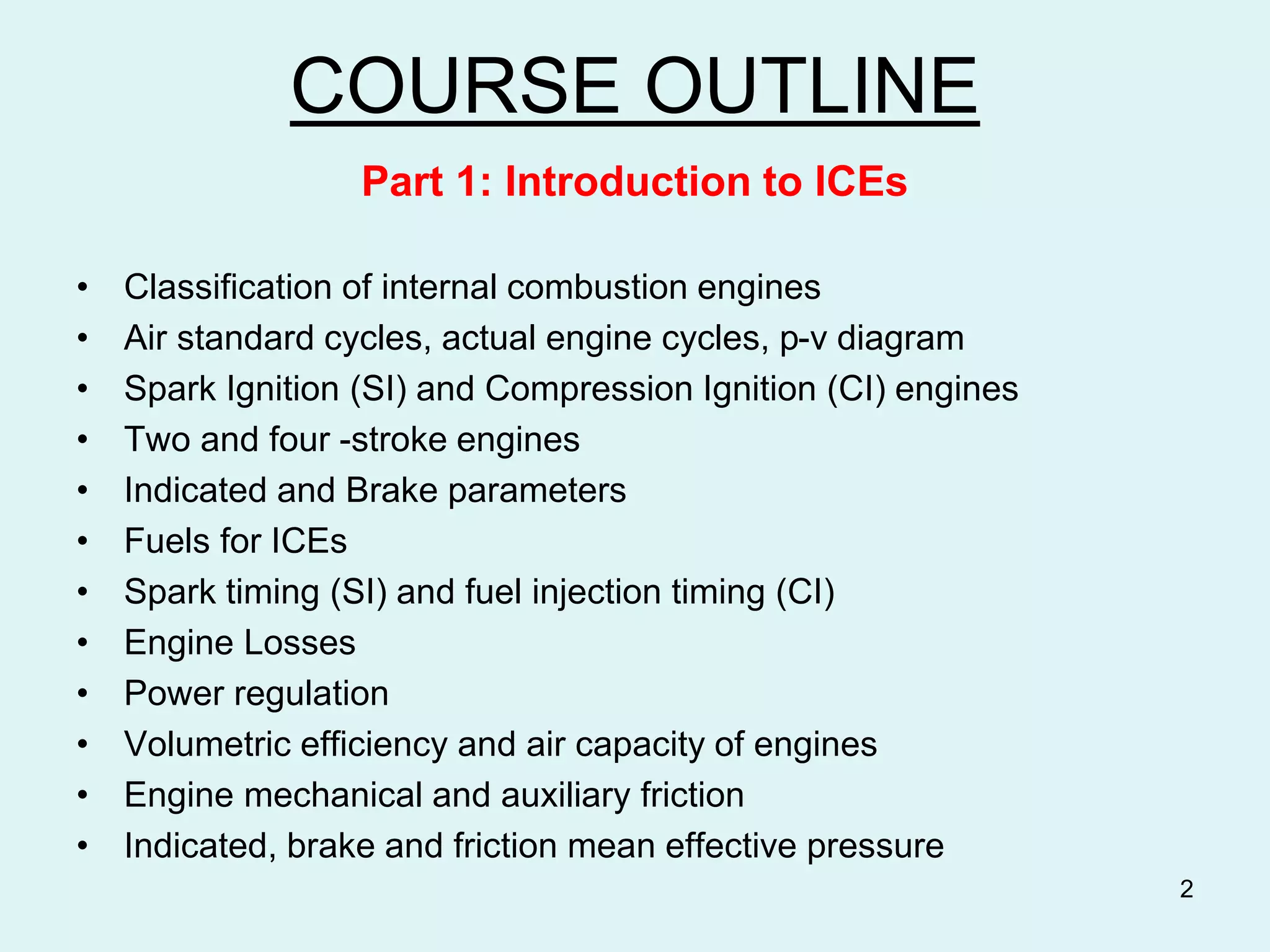
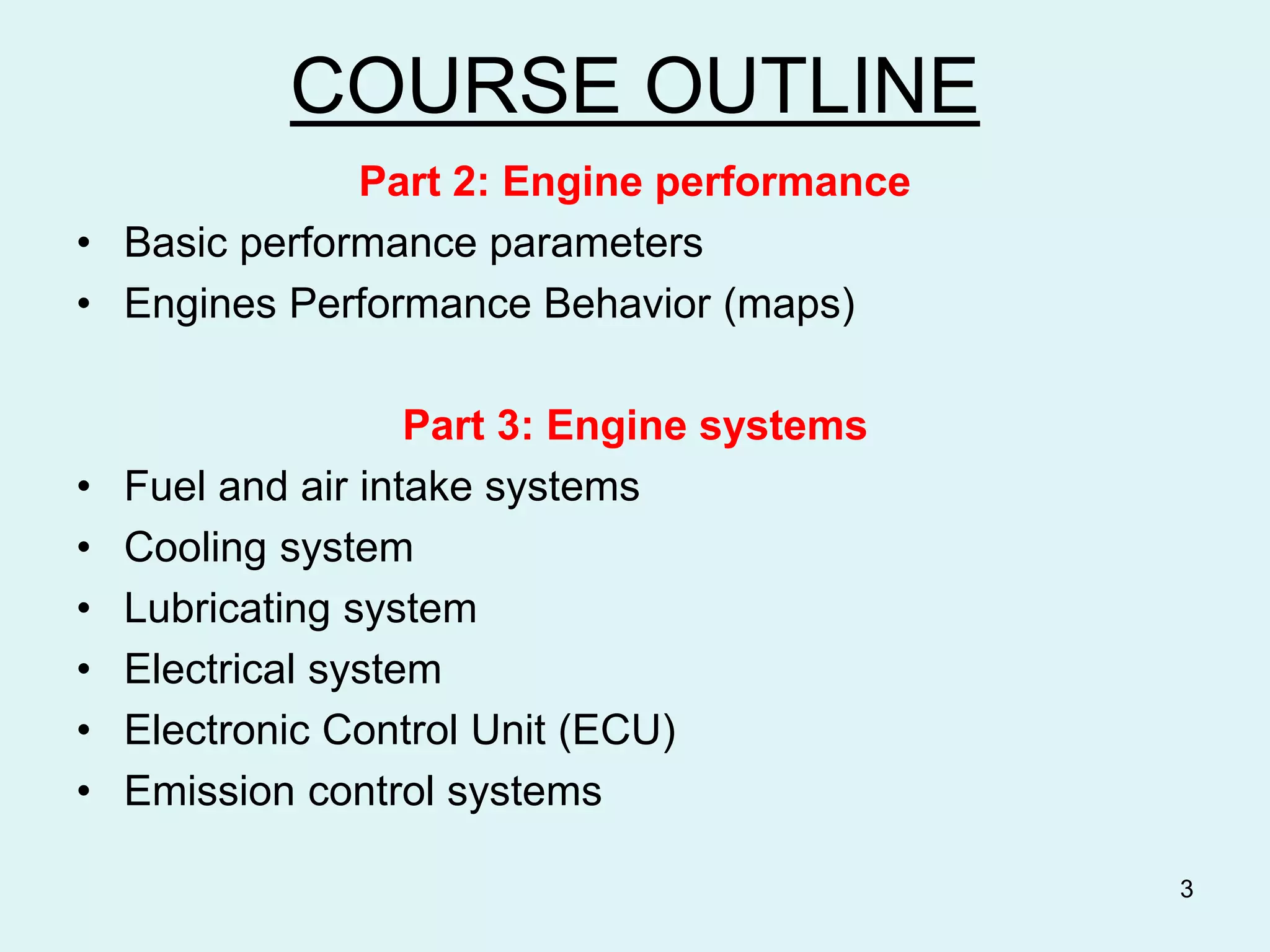
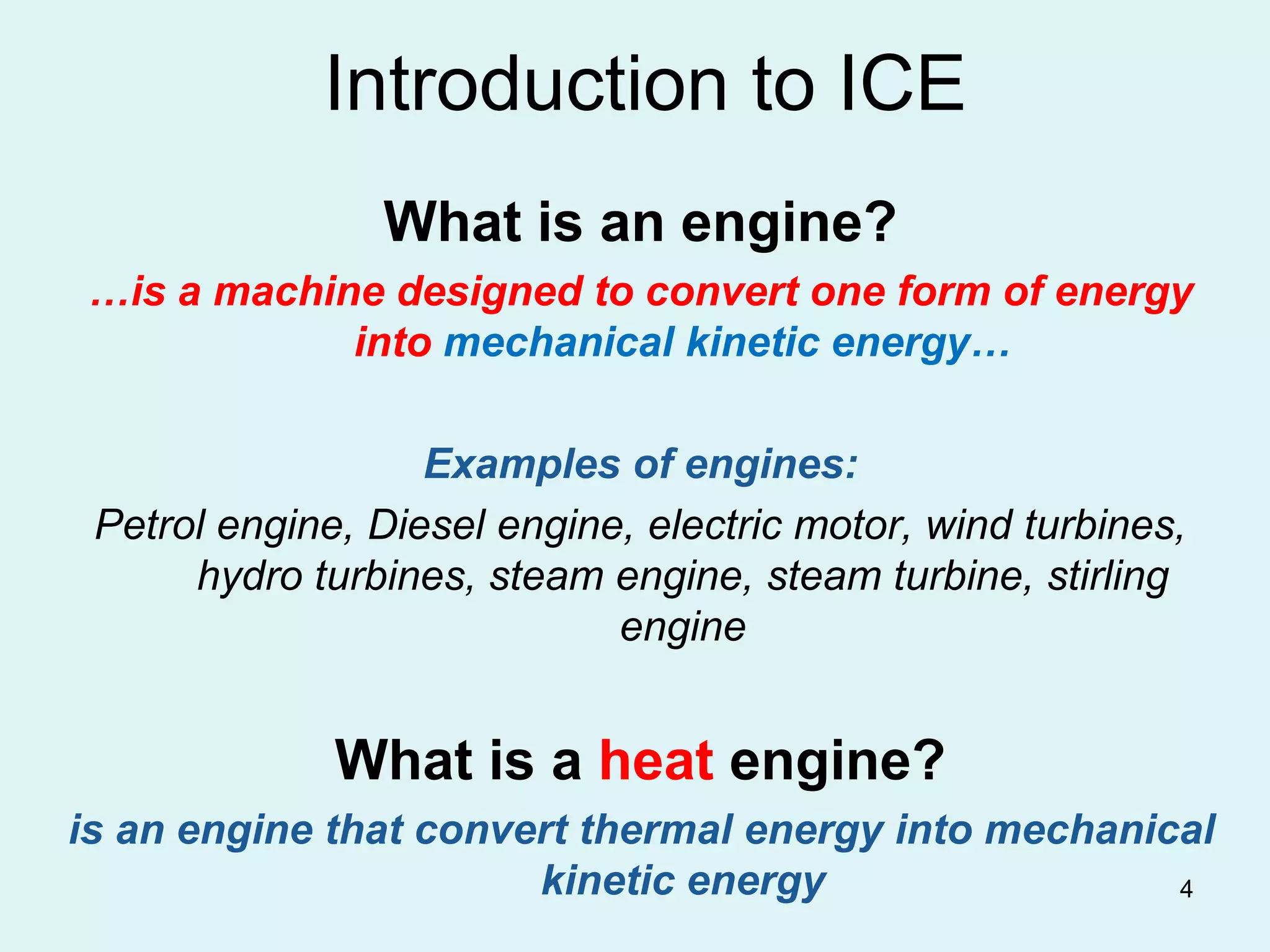
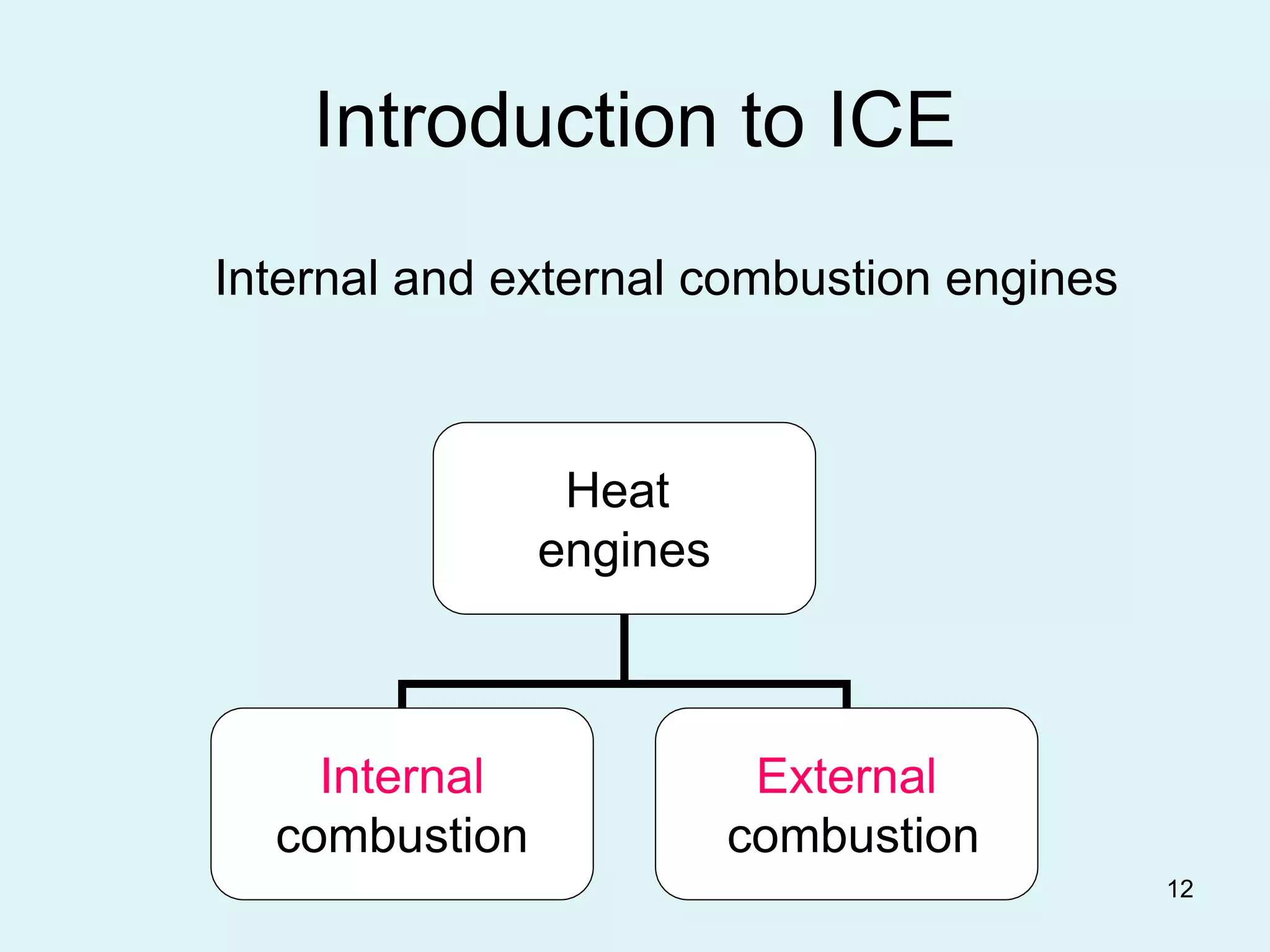
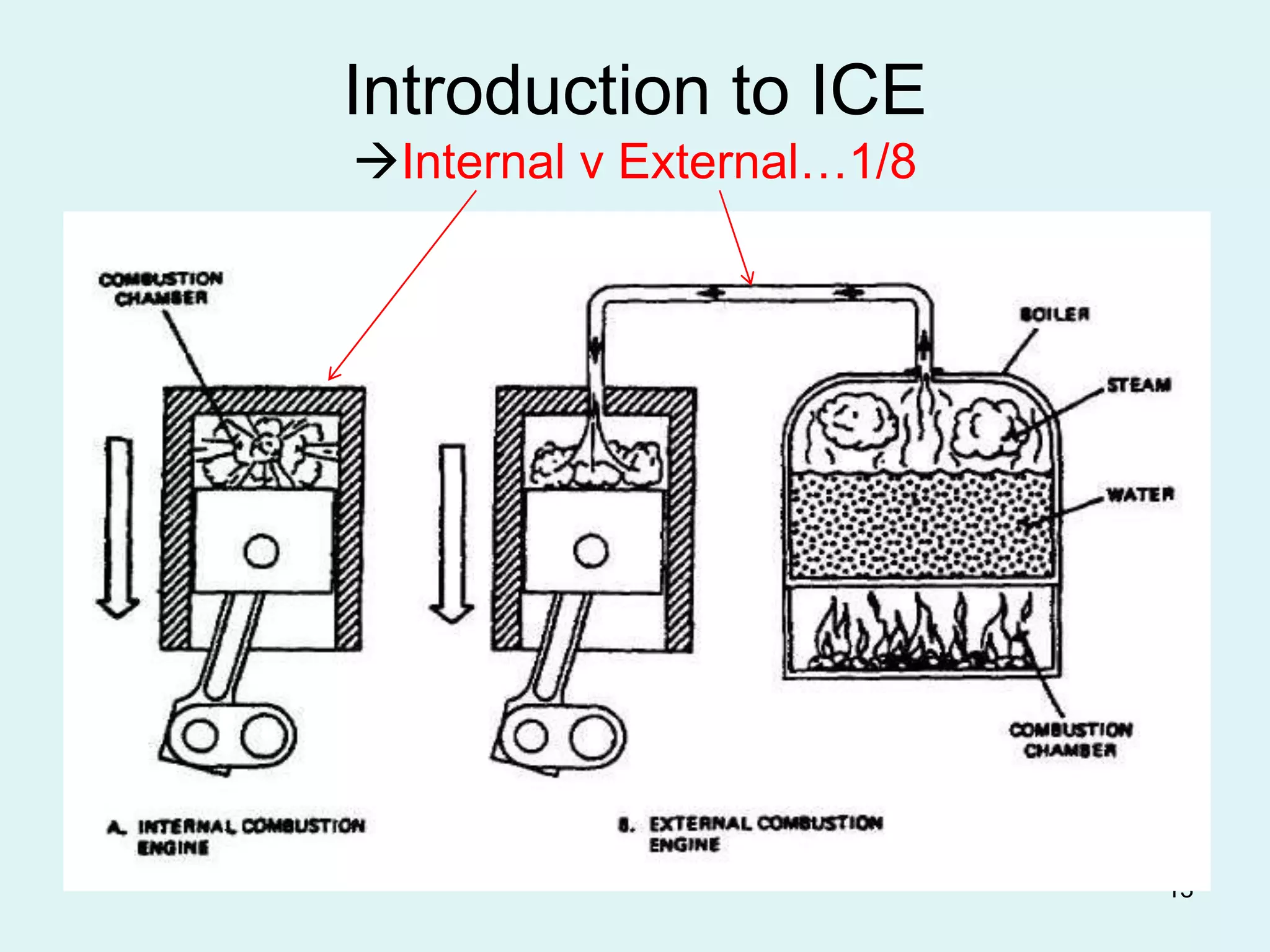
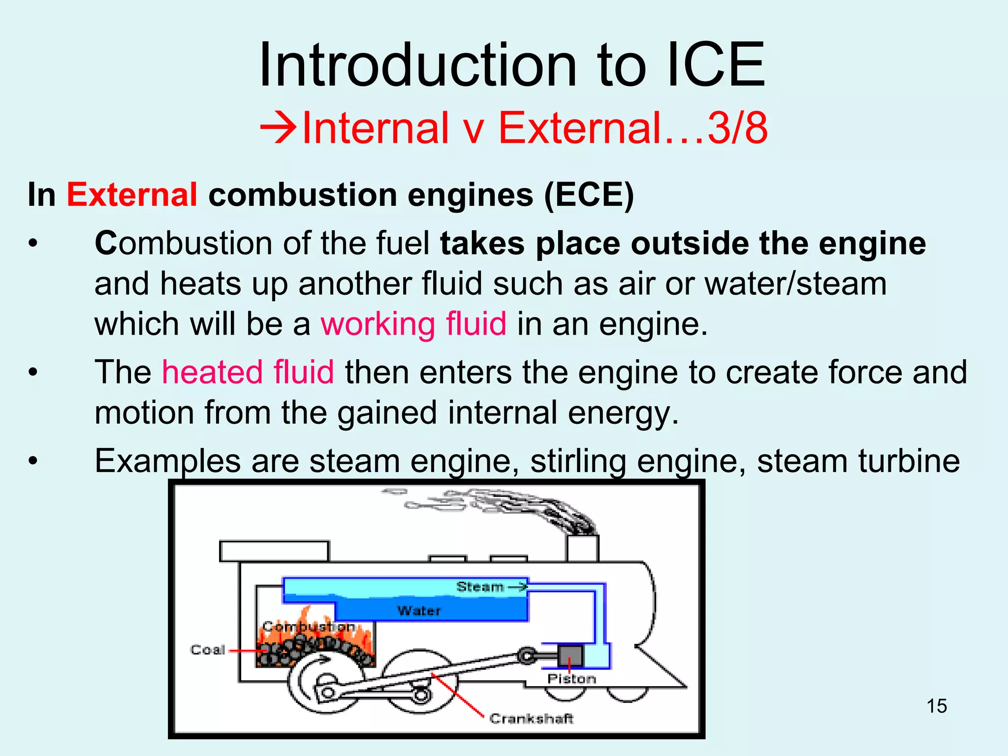
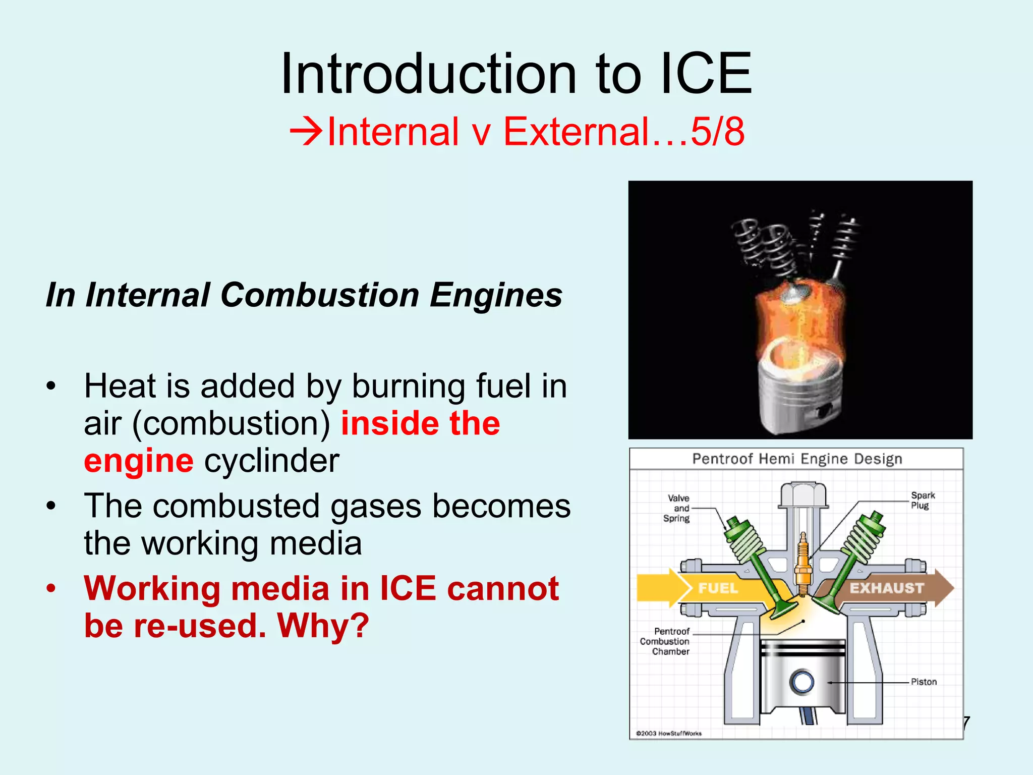
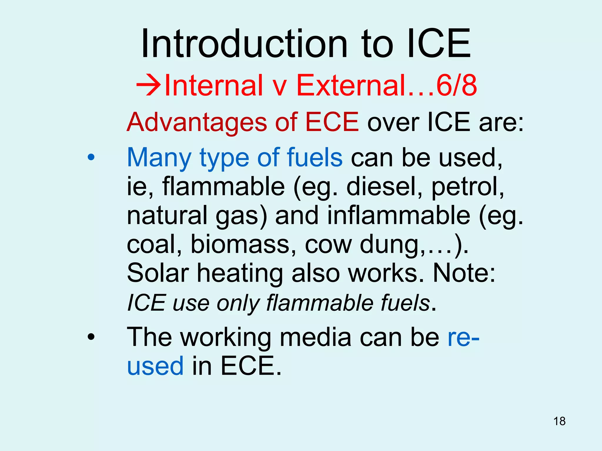
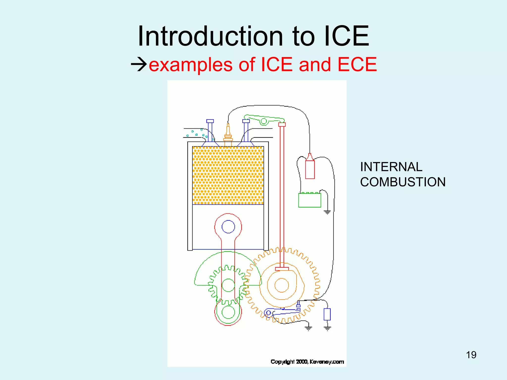
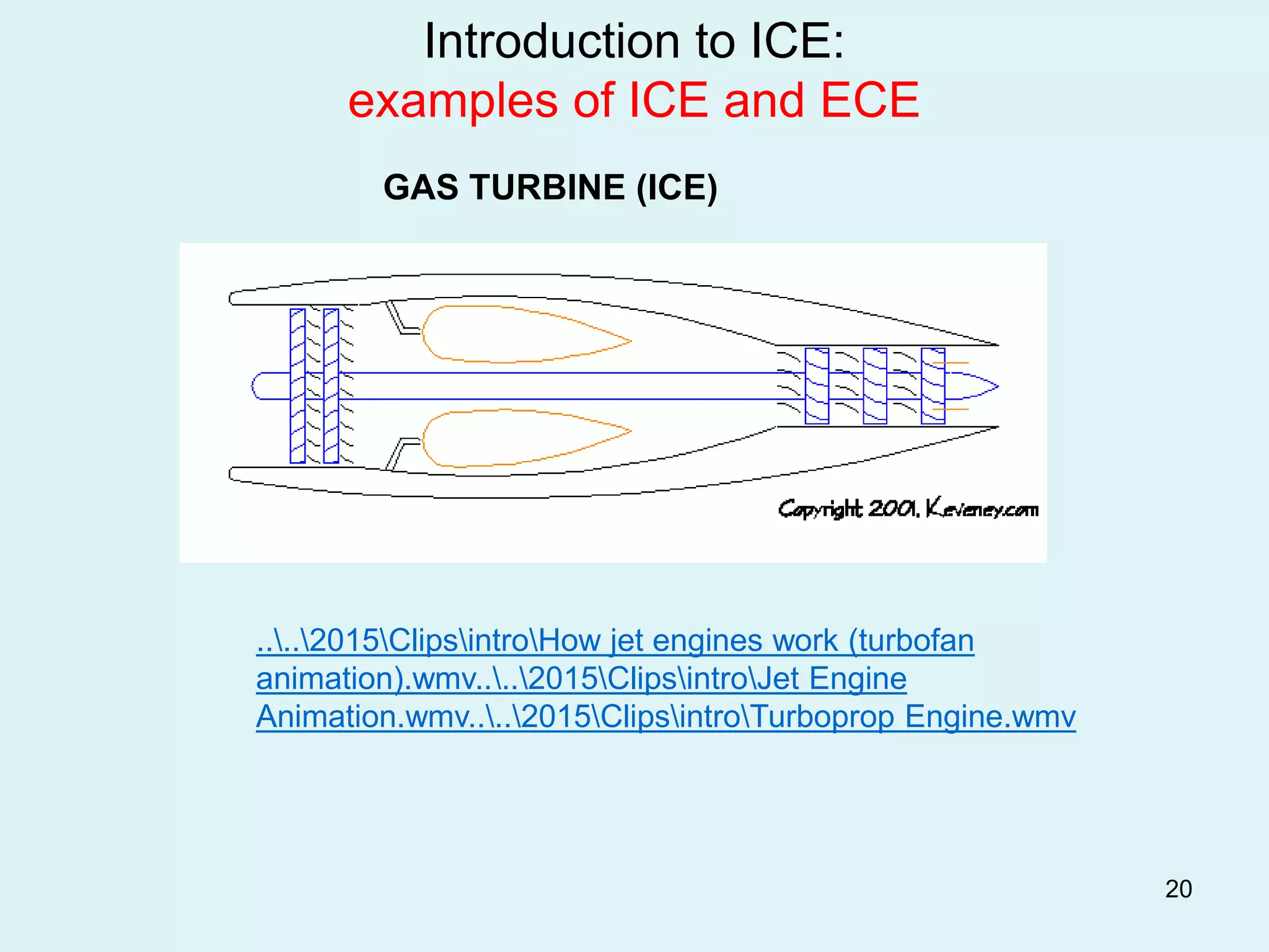
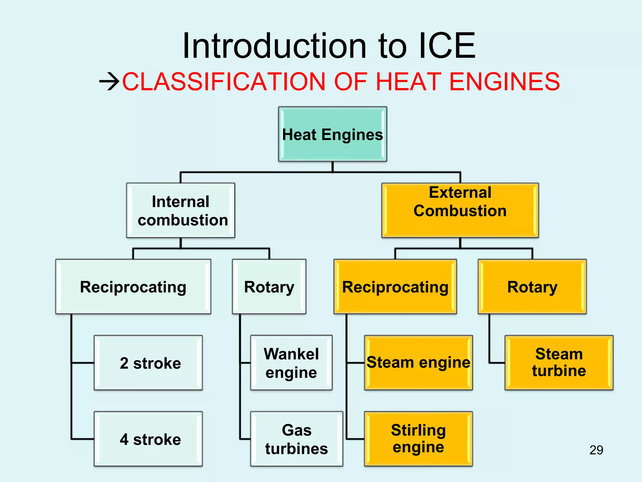
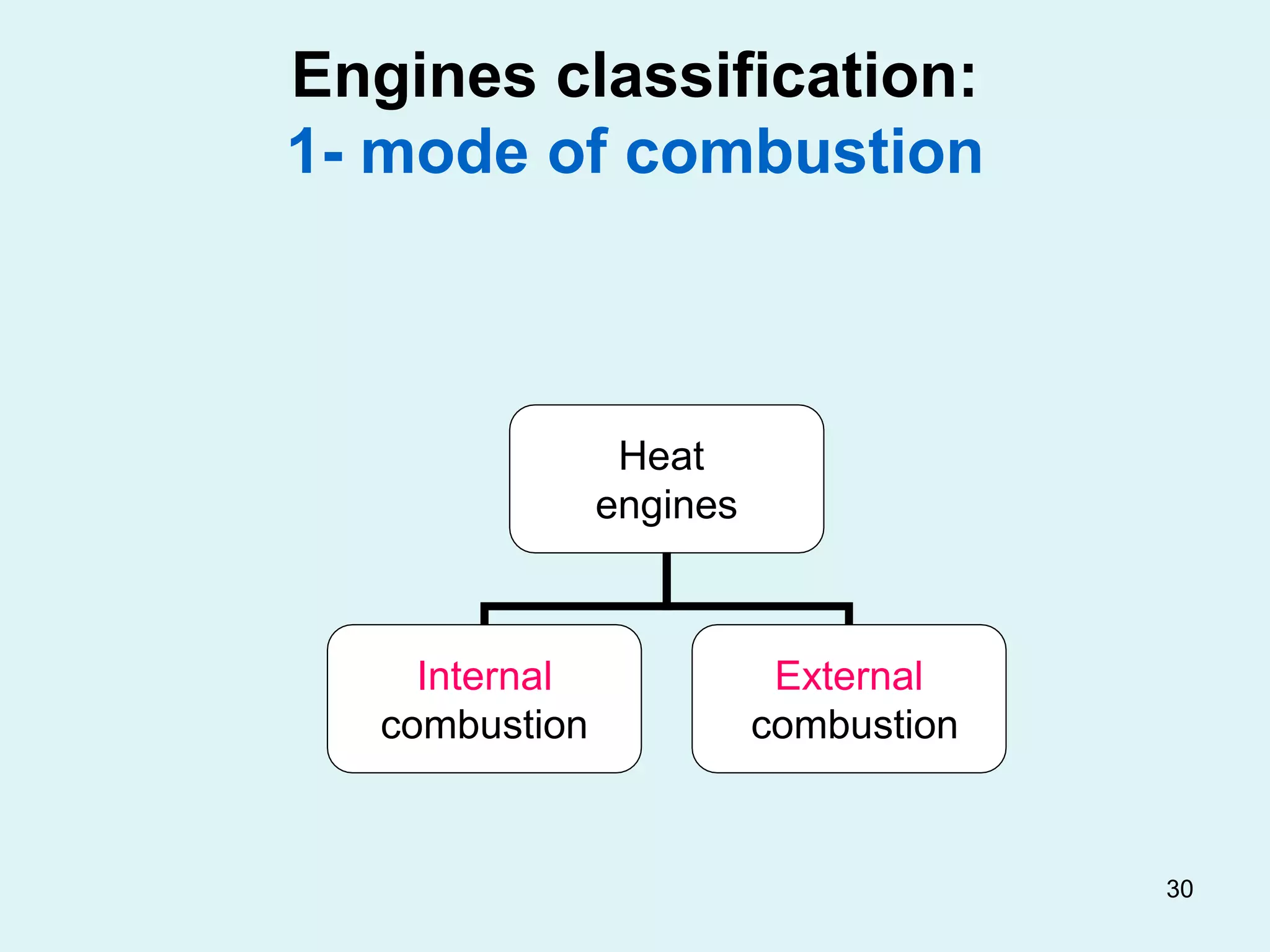
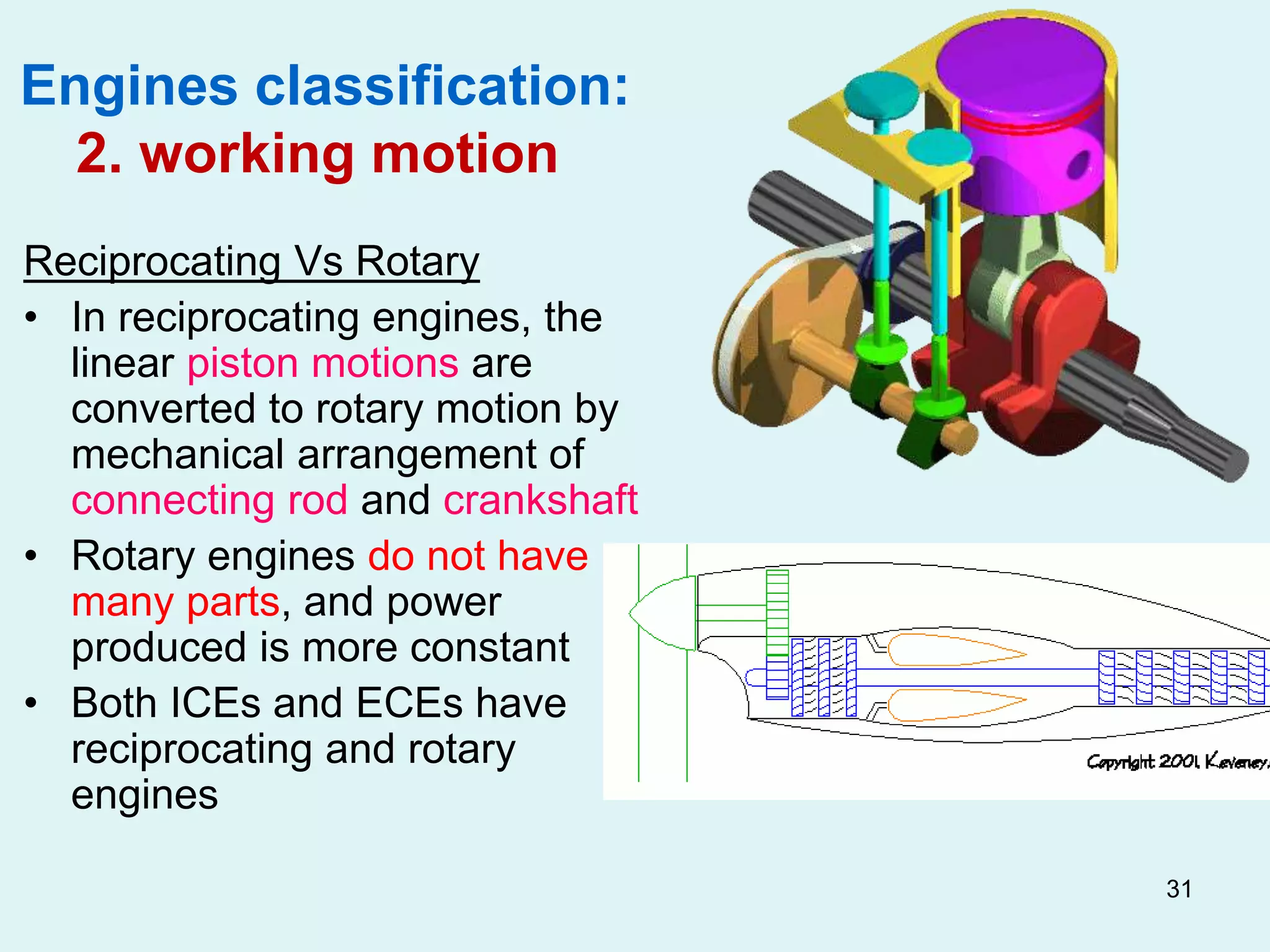
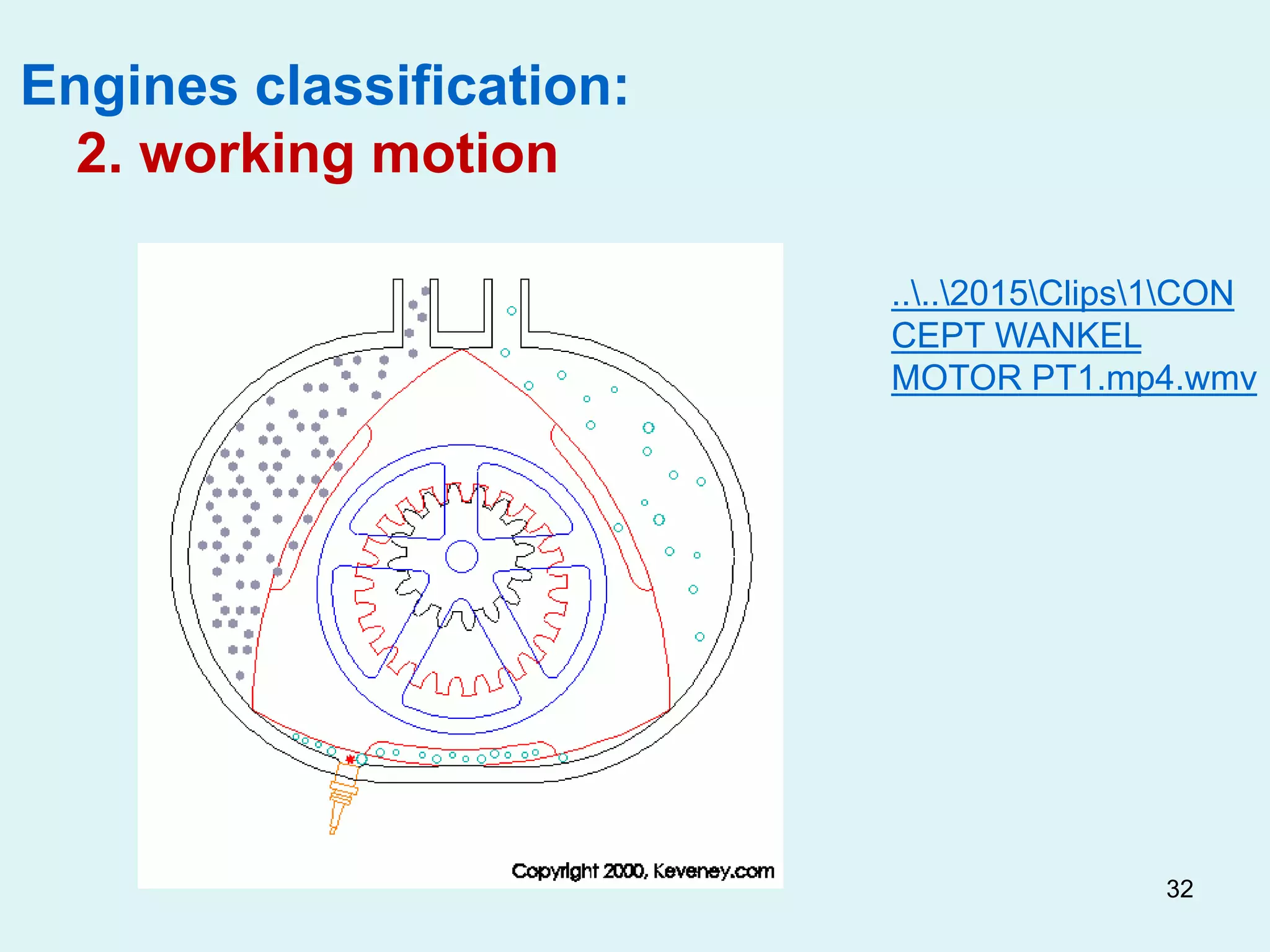
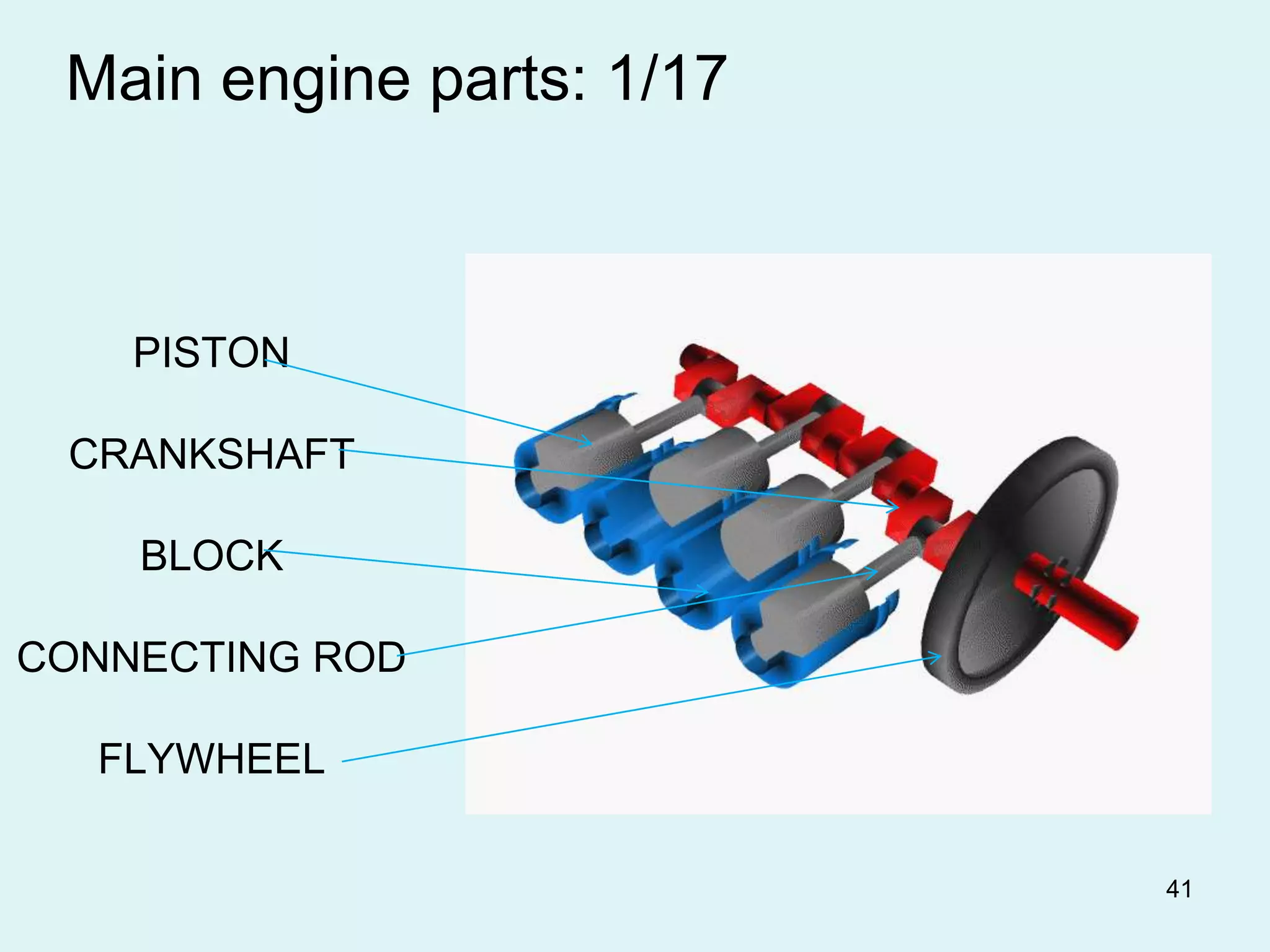
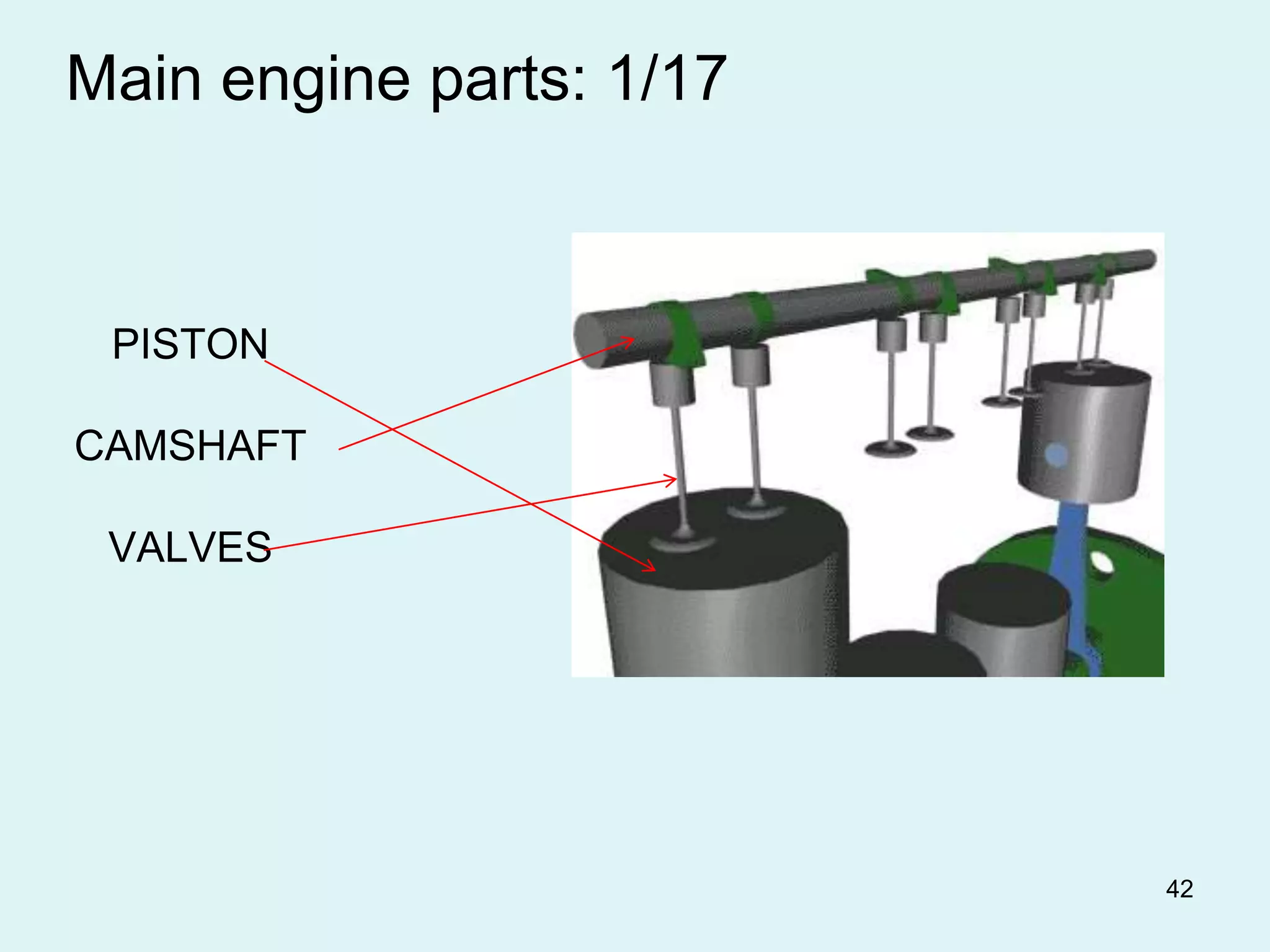
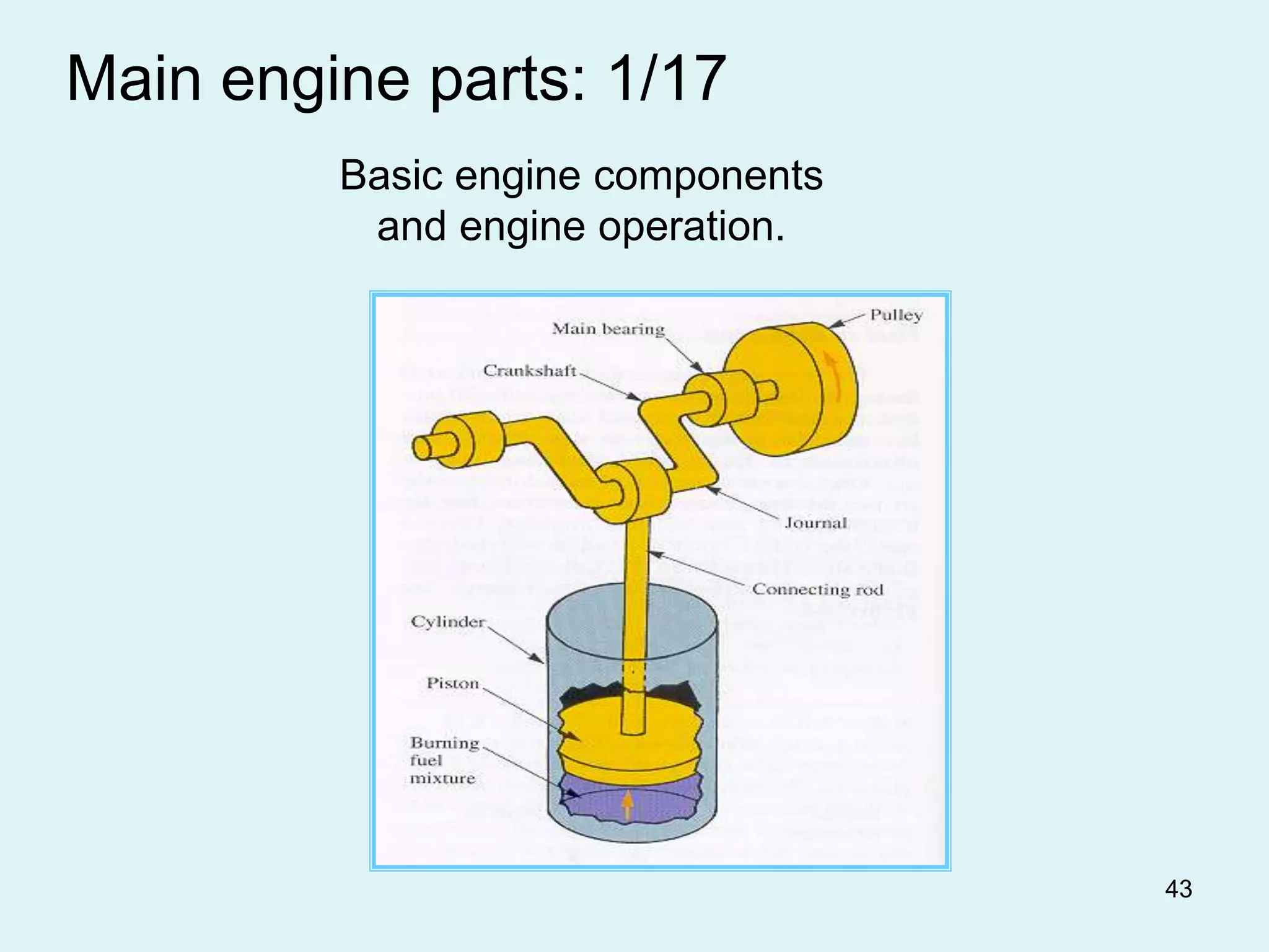

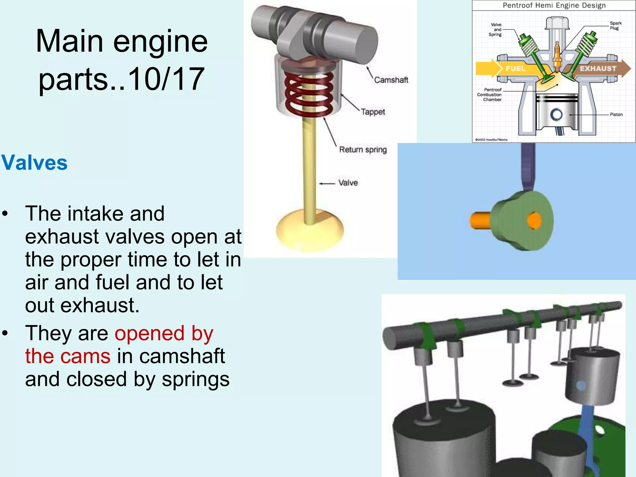
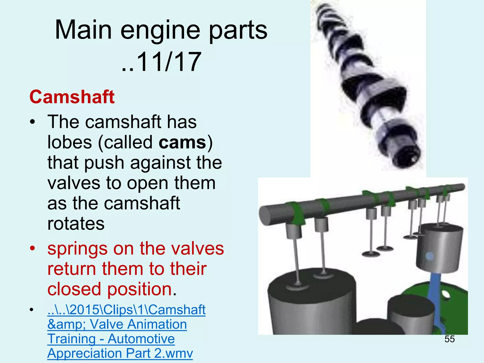
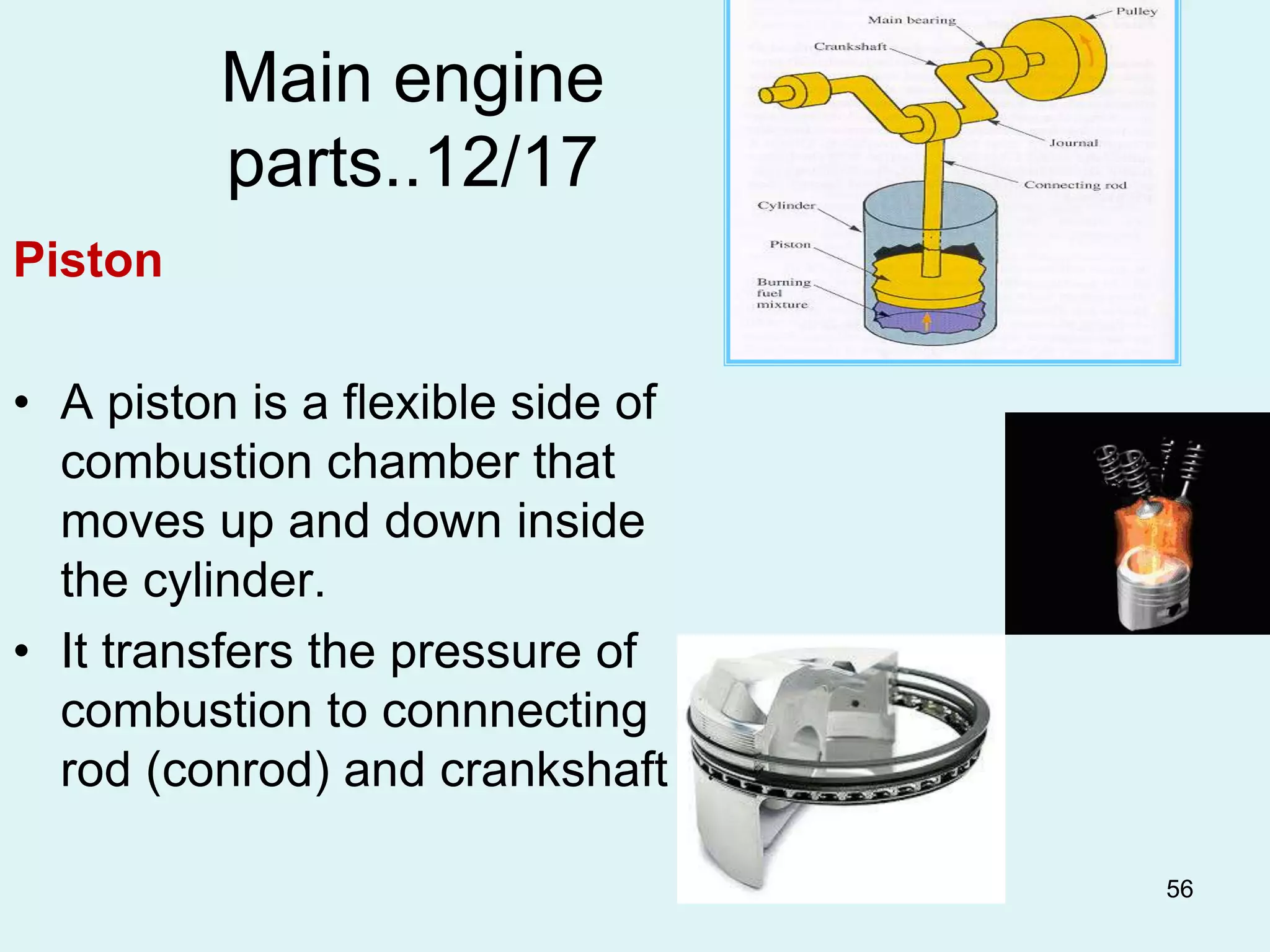
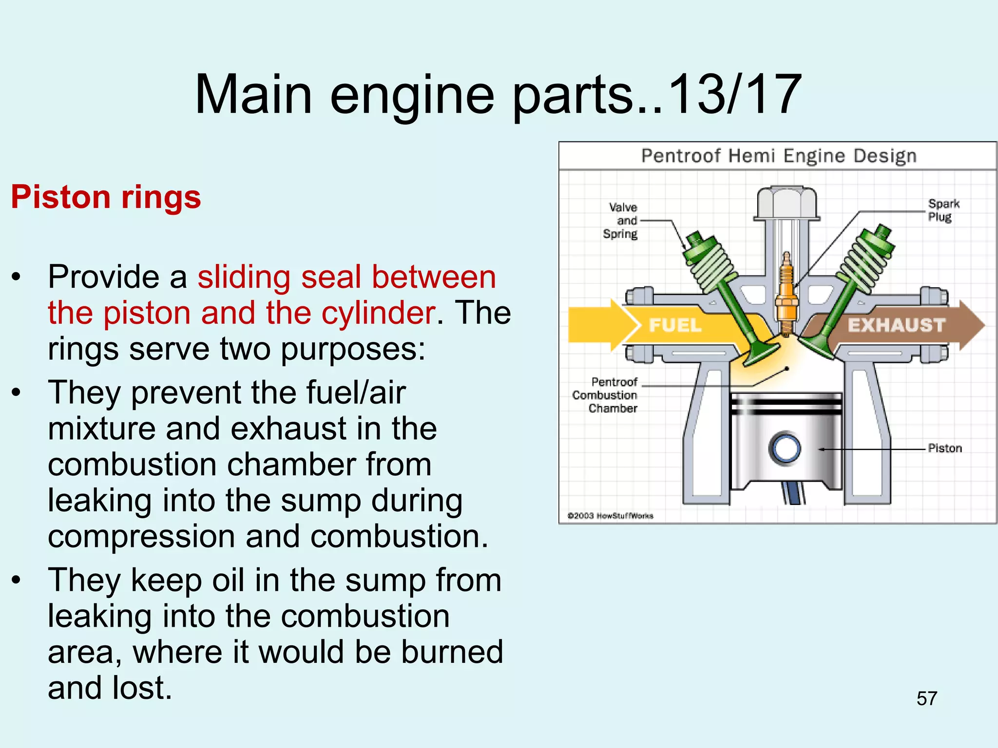
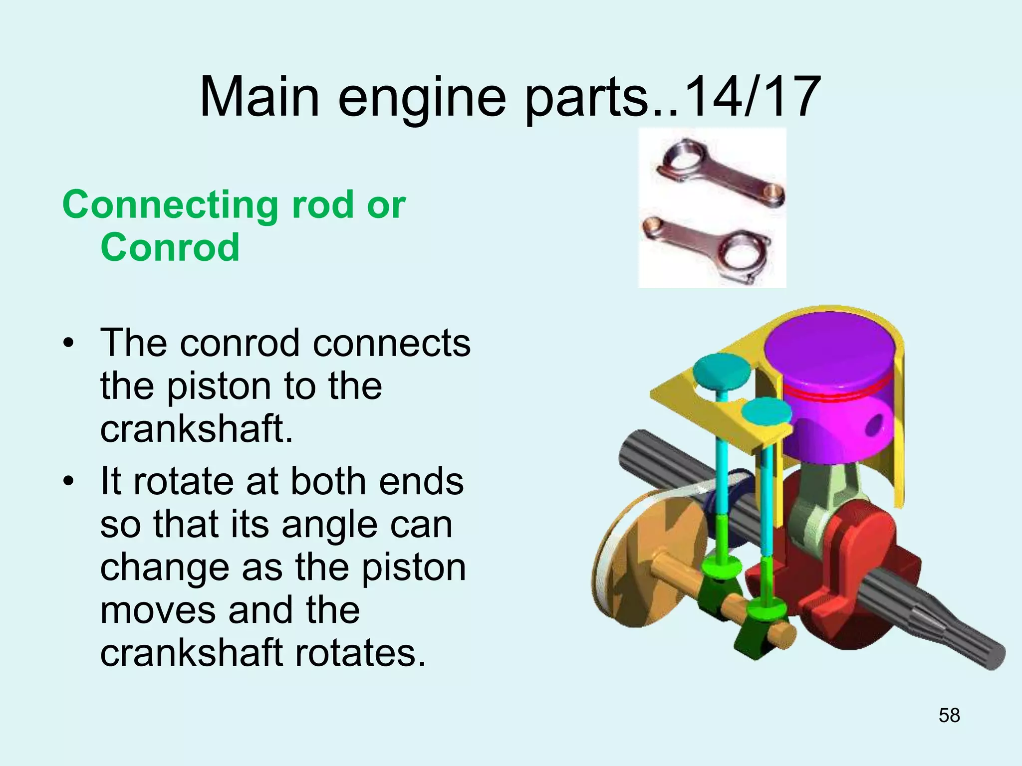
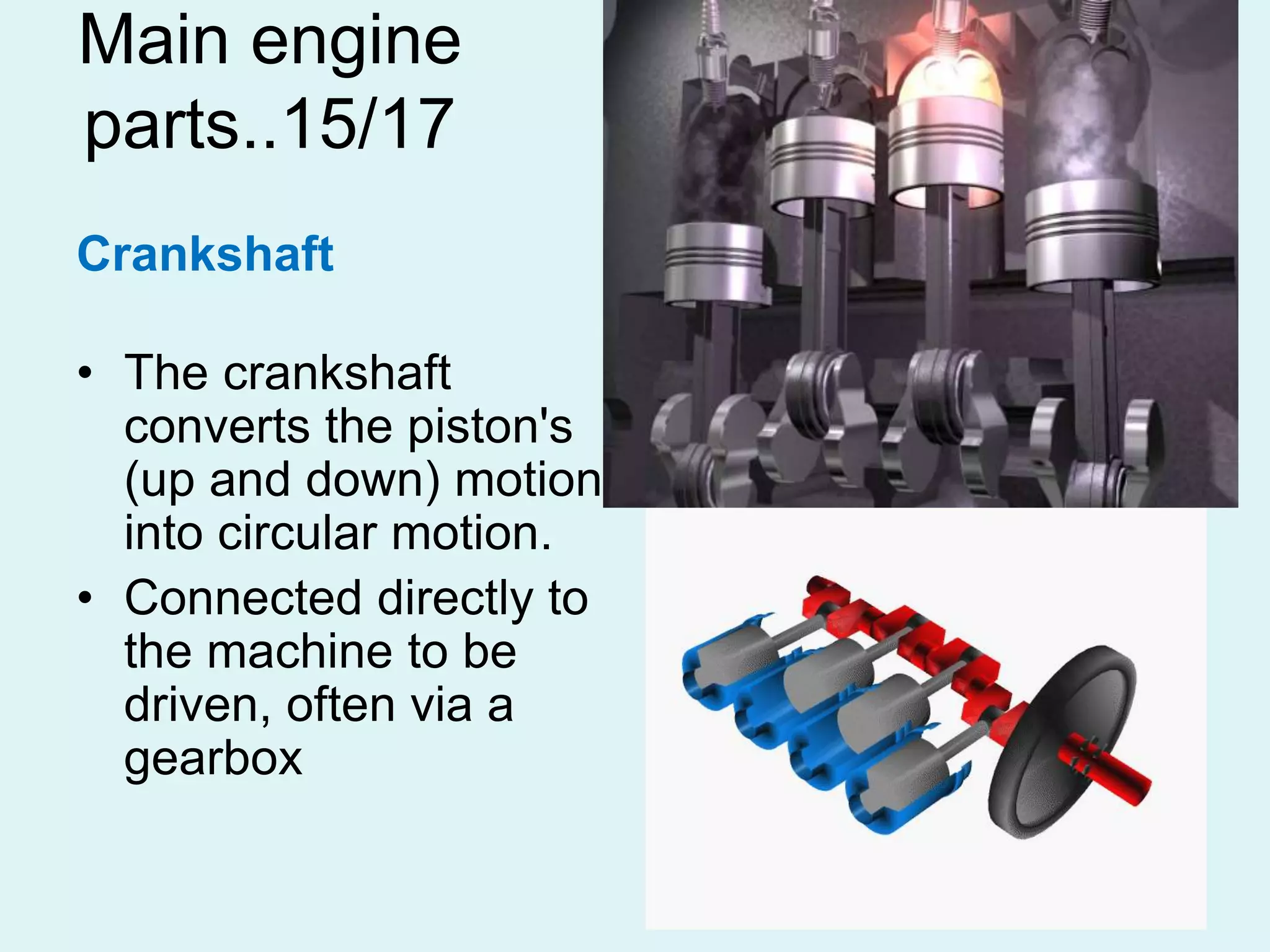
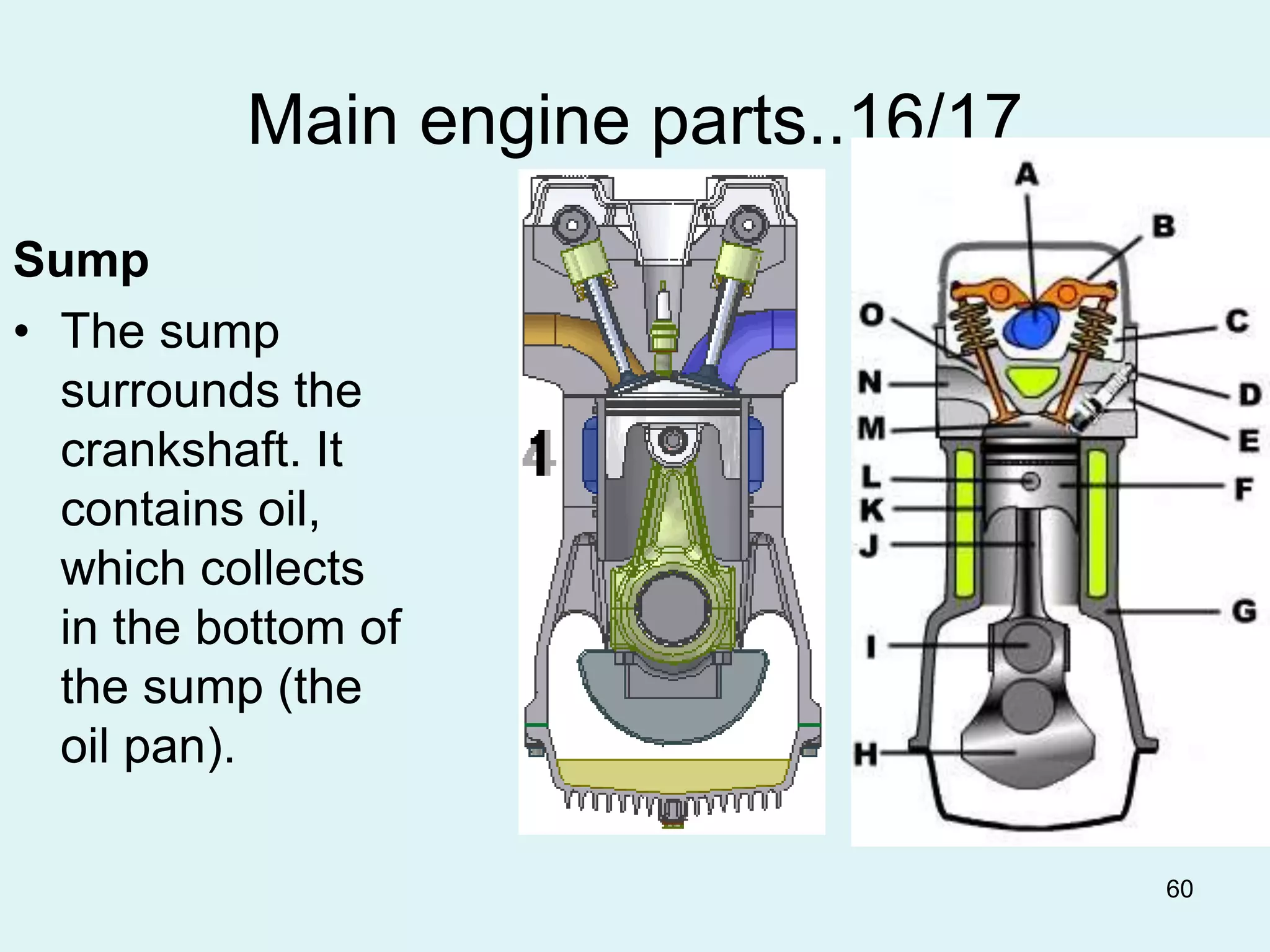
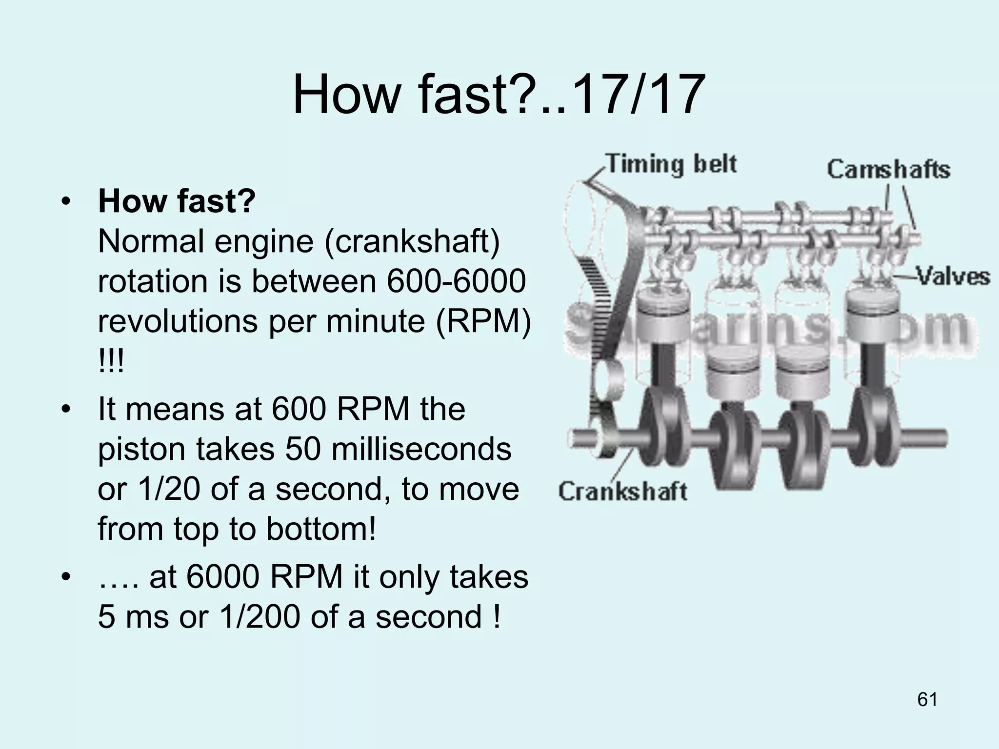

The document provides an outline for the course ME329: Internal Combustion Engines. It covers three parts: 1) Introduction to ICEs, discussing types of engines and fuel systems. 2) Engine performance parameters and behavior. 3) Engine systems such as fuel, air intake, cooling, lubrication, electrical, emissions control. It also defines key engine components like the piston, crankshaft, valves and their functions in converting combustion energy to mechanical work in the engine cycle.


