This is the Highly Detailed factory service repair manual for the1990 YAMAHA EXCITER 570 SNOWMOBILE, this Service Manual has detailed illustrations as well as step by step instructions,It is 100 percents complete and intact. they are specifically written for the do-it-yourself-er as well as the experienced mechanic.1990 YAMAHA EXCITER 570 SNOWMOBILE Service Repair Workshop Manual provides step-by-step instructions based on the complete dis-assembly of the machine. It is this level of detail, along with hundreds of photos and illustrations, that guide the reader through each service and repair procedure. Complete download comes in pdf format which can work under all PC based windows operating system and Mac also, All pages are printable. Using this repair manual is an inexpensive way to keep your vehicle working properly.
Service Repair Manual Covers:
General Information
Periodic Inspections and Adjustments
Engine Overhaul
Cooling System
Carburetion
Power Train
Chassis
Electrical
Appendices
File Format: PDF
Compatible: All Versions of Windows & Mac
Language: English
Requirements: Adobe PDF Reader
NO waiting, Buy from responsible seller and get INSTANT DOWNLOAD, Without wasting your hard-owned money on uncertainty or surprise! All pages are is great to have1990 YAMAHA EXCITER 570 SNOWMOBILE Service Repair Workshop Manual.
Looking for some other Service Repair Manual,please check:
https://www.aservicemanualpdf.com/
Thanks for visiting!
1989 Yamaha Exciter 570 Snowmobile Service Repair Manualyehnmdm jnkmem
This is the Highly Detailed factory service repair manual for the1989 YAMAHA EXCITER 570 SNOWMOBILE, this Service Manual has detailed illustrations as well as step by step instructions,It is 100 percents complete and intact. they are specifically written for the do-it-yourself-er as well as the experienced mechanic.1989 YAMAHA EXCITER 570 SNOWMOBILE Service Repair Workshop Manual provides step-by-step instructions based on the complete dis-assembly of the machine. It is this level of detail, along with hundreds of photos and illustrations, that guide the reader through each service and repair procedure. Complete download comes in pdf format which can work under all PC based windows operating system and Mac also, All pages are printable. Using this repair manual is an inexpensive way to keep your vehicle working properly.
Service Repair Manual Covers:
General Information
Periodic Inspections and Adjustments
Engine Overhaul
Cooling System
Carburetion
Power Train
Chassis
Electrical
Appendices
File Format: PDF
Compatible: All Versions of Windows & Mac
Language: English
Requirements: Adobe PDF Reader
NO waiting, Buy from responsible seller and get INSTANT DOWNLOAD, Without wasting your hard-owned money on uncertainty or surprise! All pages are is great to have1989 YAMAHA EXCITER 570 SNOWMOBILE Service Repair Workshop Manual.
Looking for some other Service Repair Manual,please check:
https://www.aservicemanualpdf.com/
Thanks for visiting!
8
This document contains 11 multi-step physics problems involving fluid mechanics concepts like pressure, viscosity, density, and fluid flow. The problems are solved with relevant equations for ideal gases, compressible fluids, laminar flow, and viscometry. Key values are calculated, such as mass, pressure, shear stress, drag force, velocity, and viscosity.
This document discusses simple harmonic motion and elasticity. It begins by defining simple harmonic motion as back-and-forth motion caused by a restoring force proportional to displacement, with displacement centered around an equilibrium position. It then discusses Hooke's law, where the restoring force of an ideal spring is directly proportional to displacement. Several equations for simple harmonic motion are presented, including those relating displacement, velocity, acceleration, period, frequency, and amplitude. Examples are provided to illustrate these concepts for springs and pendulums undergoing simple harmonic motion.
This document is an instruction manual for the TOSVERT VF-A7 high-performance inverter. It contains important safety precautions and instructions for installation, wiring, operation, inspection, maintenance, and disposal of the inverter. Key points include:
- Warnings about electric shock hazards and ensuring the inverter is de-energized before working on it.
- Prohibitions against modifications, water/chemical exposure, improper wiring or operation.
- Mandatory instructions for safe transport, installation, grounding, use of safety devices, and licensed industrial waste disposal.
- Cautions regarding automatic restart functions and labeling requirements.
1987 Yamaha Exciter 570 Snowmobile Service Repair Manualhjjsenmd poiuik
This is the Highly Detailed factory service repair manual for the1987 YAMAHA EXCITER 570 SNOWMOBILE, this Service Manual has detailed illustrations as well as step by step instructions,It is 100 percents complete and intact. they are specifically written for the do-it-yourself-er as well as the experienced mechanic.1987 YAMAHA EXCITER 570 SNOWMOBILE Service Repair Workshop Manual provides step-by-step instructions based on the complete dis-assembly of the machine. It is this level of detail, along with hundreds of photos and illustrations, that guide the reader through each service and repair procedure. Complete download comes in pdf format which can work under all PC based windows operating system and Mac also, All pages are printable. Using this repair manual is an inexpensive way to keep your vehicle working properly.
Service Repair Manual Covers:
General Information
Periodic Inspections and Adjustments
Engine Overhaul
Cooling System
Carburetion
Power Train
Chassis
Electrical
Appendices
File Format: PDF
Compatible: All Versions of Windows & Mac
Language: English
Requirements: Adobe PDF Reader
NO waiting, Buy from responsible seller and get INSTANT DOWNLOAD, Without wasting your hard-owned money on uncertainty or surprise! All pages are is great to have1987 YAMAHA EXCITER 570 SNOWMOBILE Service Repair Workshop Manual.
Looking for some other Service Repair Manual,please check:
https://www.aservicemanualpdf.com/
Thanks for visiting!
laws of thermodynamics ... elements of mechanical engineeringstanley christy
This document is a presentation on the laws of thermodynamics given by Jay Shah, Stanley Chisty, and Rutvik Shah to their classmates. It introduces the first law of thermodynamics as the law of conservation of energy, and provides examples of cycling and melting ice. The second law is summarized as entropy always increasing over time for isolated systems. Examples given are heat transfer from hot to cold. The zeroth law is stated as if A=C and B=C then A=B in thermal equilibrium. An example of tea, coffee, and the environment is also provided.
1. The document discusses concepts related to kinetics of particles including work, kinetic energy, and their relationship as described by the principle of work and energy. It provides equations and examples to calculate work, kinetic energy, and velocity using this principle.
2. Sample problems are presented to demonstrate applications of the principle to problems involving forces like gravity, springs, friction, and combinations of forces. The principle is used to determine velocities, distances, and other quantities without directly calculating acceleration.
3. Key concepts covered include work of constant and variable forces, work-energy theorem, power, efficiency, and applications to problems like blocks on an incline, springs, and motion down tracks. Diagrams and step-by-step solutions
Static electricity is an imbalance of electric charges within or on the surface of a material. It is created whenever two surfaces contact and separate, with at least one surface having a high resistance. The interaction of static electric charges is called electrostatics. Static electricity results from the triboelectric effect, where electrons are exchanged between materials on contact, resulting in one material becoming positively charged and the other negatively charged. Excess static charge can be removed or prevented by increasing moisture, using an air ionizer, or applying antistatic agents. Static discharge occurs as excess charge is neutralized by flowing to the surroundings, which can cause sparks responsible for industrial fires.
Compair cyclon-3 air compressor user manual-parts supplierdaisy Airmax
shanghai airmax co.,ltd is the compair compressor parts supplier. we can provide the complete filters replacement for Compair screw air compressors. please contact info@aircompressor-filter.com
This summary provides the key details about four failure theories in 3 sentences:
The document discusses four common failure theories: 1) Maximum shear stress (Tresca) theory, which predicts failure when maximum shear stress equals yield stress, applies to ductile materials. 2) Maximum principal stress (Rankine) theory, which predicts failure when largest principal stress reaches ultimate stress. 3) Maximum normal strain (Saint Venant) theory, which predicts failure when maximum normal strain equals yield strain. 4) Maximum shear strain (distortion energy) theory, which predicts failure when distortion energy per unit volume equals strain energy at failure. The theories attempt to predict failure of materials subjected to multiaxial stress states.
This document discusses mechanics concepts related to tension, forces, and motion. It covers tension in strings, non-accelerated environments like inclined planes and pulleys, and accelerated environments. Friction and its effects on motion up and down inclined planes are analyzed. Other topics discussed include contact forces, motion on frictionless planes, flying of birds using air displacement, braking on bicycles, and applying conservation of momentum to moving trolleys and objects. Diagrams and equations are provided for each concept.
This document outlines the key concepts and objectives covered in Chapter 1 of an engineering mechanics textbook. It introduces the fundamental topics of mechanics including particles, rigid bodies, Newton's laws of motion and gravitation. It also reviews the SI system of units and procedures for dimensional analysis, significant figures and numerical calculations. The objectives are to provide an introduction to the basic concepts and quantitative methods of mechanics.
time domain analysis, Rise Time, Delay time, Damping Ratio, Overshoot, Settli...Waqas Afzal
Time Response- Transient, Steady State
Standard Test Signals- U(t), S(t), R(t)
Analysis of First order system - for Step input
Analysis of second order system -for Step input
Time Response Specifications- Rise Time, Delay time, Damping Ratio, Overshoot, Settling Time
Calculations
1. The background of Fluid Mechanics
2. Fields of Fluid mechanics
3. Introduction and Basic concepts
4. Properties of Fluids
5. Pressure and fluid statics
6. Hydrodynamics
The document discusses the response of first and second order systems. It defines poles and zeros as values that make the transfer function infinite or zero. For first order systems, it describes the transient response as gradual change from initial to final output. The time constant determines how quickly the system responds. For second order systems, the natural frequency and damping ratio characterize the response. Underdamped systems oscillate with declining amplitude, with specifications like rise time and settling time defined.
The document provides information on the basic properties of fuel used in diesel engines, including mass density of fuel at standard and other temperatures, and heating or calorific values including higher heating value (HHV) and lower heating value (LHV). It also gives sample problems calculating engine properties like indicated power, brake power, mechanical efficiency, and thermal efficiency based on fuel consumption, heating value, temperature and other engine operating parameters.
The document discusses various topics related to stress and strain including: principal stresses and strains, Mohr's stress circle theory of failure, 3D stress and strain, equilibrium equations, and impact loading. It provides examples of stresses acting in different planes including normal, shear, oblique, and principal planes. It also gives examples of calculating normal and tangential stresses on an oblique plane subjected to stresses in one, two, or multiple directions with and without shear stresses.
The document summarizes Newton's three laws of motion and other key concepts in mechanics. It discusses Newton's first law of inertia, second law relating force and acceleration, and third law of equal and opposite reaction. It also defines concepts like impulse, momentum, work, energy, and power. Key principles discussed include conservation of linear momentum, mechanical energy, and total energy in a closed system.
This document summarizes the roles for three actors in an upcoming short film. Actor 1 will play an unseen antagonist wearing a hoodie or hat to conceal their face. Actor 2 will play a scared student who is smaller in stature than the bully. Brandon King is chosen for this role. Actor 3 will play the bully and needs to be tall to tower over the scared student and appear imposing. Either Mark Blanchard or Henry Pool are suitable for this role due to their tall statures. Physical characteristics are less important than being able to fulfill the size requirements of each role.
KOM - Unit 2 -kinematics of linkage mechanismkarthi keyan
This document discusses kinematics concepts related to linkages and mechanisms. It covers distance and displacement, instantaneous center of rotation, velocity using the instantaneous center method, types and number of instantaneous centers, angular velocity ratio theorem, significance of coincident points including coriolis acceleration, and an overview of kinematic synthesis including stages and types of synthesis problems.
Heat is transferred between objects or materials through conduction. Fourier's law of heat conduction describes this process, stating that the rate of heat transfer through a material is proportional to the negative temperature gradient in the material. Thermal conductivity is a property of materials that determines their ability to conduct heat. Materials with high thermal conductivity are good conductors, while those with low conductivity are thermal insulators.
Exercise 1a transfer functions - solutionswondimu wolde
This document provides information about the course EE4107 - Cybernetics Advanced, including:
- An overview of transfer functions and how they are represented mathematically using numerators and denominators related to zeros and poles.
- How transfer functions can be derived from differential equations using Laplace transforms.
- Functions in MathScript that can be used to define transfer functions and analyze system responses.
- Examples of converting differential equations into transfer functions by taking the Laplace transform.
The document discusses particle kinematics and concepts such as displacement, velocity, acceleration, and their relationships for rectilinear and curvilinear motion. Key concepts covered include definitions of displacement, average and instantaneous velocity, acceleration, graphical representations of position, velocity, and acceleration over time, and analytical methods for solving kinematic equations involving constant or variable acceleration. Several sample problems are provided to illustrate applying these kinematic concepts and relationships to solve for variables like time, velocity, acceleration, and displacement given relevant conditions.
1990 Kawasaki KLF220-A3 Bayou Service Repair Manualjksmrrmmd
This is the Highly Detailed factory service repair manual for the1990 KAWASAKI KLF220-A3 BAYOU, this Service Manual has detailed illustrations as well as step by step instructions,It is 100 percents complete and intact. they are specifically written for the do-it-yourself-er as well as the experienced mechanic.1990 KAWASAKI KLF220-A3 BAYOU Service Repair Workshop Manual provides step-by-step instructions based on the complete dis-assembly of the machine. It is this level of detail, along with hundreds of photos and illustrations, that guide the reader through each service and repair procedure. Complete download comes in pdf format which can work under all PC based windows operating system and Mac also, All pages are printable. Using this repair manual is an inexpensive way to keep your vehicle working properly.
Service Repair Manual Covers:
General Information
Periodic Maintenance
Fuel System
Cooling System
Engine Top End
Converter System
Engine Lubrication System
Engine Removal / Installation
Crankshaft / Transmission
Wheels / Tires
Final Drive
Brakes
Suspension
Steering
Frame
Electrical System
Appendix
File Format: PDF
Compatible: All Versions of Windows & Mac
Language: English
Requirements: Adobe PDF Reader
NO waiting, Buy from responsible seller and get INSTANT DOWNLOAD, Without wasting your hard-owned money on uncertainty or surprise! All pages are is great to have1990 KAWASAKI KLF220-A3 BAYOU Service Repair Workshop Manual.
Looking for some other Service Repair Manual,please check:
https://www.aservicemanualpdf.com/
Thanks for visiting!
8
2005 yamaha viking vk 540 series snowmobile service repair manualfjjskdmnenemm
This chapter discusses periodic inspections and adjustments for a snowmobile. It includes maintenance schedules, lubrication intervals, inspection and adjustment procedures for the shroud, engine, drive train, chassis, electrical systems, and tuning adjustments. The maintenance tasks are grouped by vehicle component and range from simple inspections to more complex procedures like adjusting ignition timing.
2000 yamaha viking vk 540 series snowmobile service repair manualfhsejkdkmem
This document provides a periodic maintenance table and instructions for inspecting and adjusting various components of a snowmobile, including the shroud, engine, powertrain, chassis, and electrical systems. The maintenance table outlines inspection and adjustment points that should be checked every 20, 40, or 80 hours of operation or seasonally. The following sections provide detailed instructions for conducting engine oil checks, idle speed adjustment, belt inspections, brake adjustments, and other routine maintenance procedures.
1998 yamaha viking vk 540 series snowmobile service repair manualfjsekkxszdmmem
This document provides maintenance and inspection procedures for a snowmobile. It includes periodic maintenance schedules and instructions for inspecting and adjusting various components including shroud covers, the engine, drive train, suspension, and electrical systems. Special tools required for tune-ups and repairs are also listed. The document aims to help owners properly maintain their snowmobile for optimal performance and safety.
1995 yamaha viking vk 540 series snowmobile service repair manualfhjsjkdmemm
This chapter outlines periodic inspections and adjustments that should be performed on the snowmobile to ensure reliable operation and a long service life. A periodic maintenance table lists specific components and systems that should be checked at regular intervals measured in hours of use or kilometers, including the engine, carburetor, drive train, brakes, tracks, and other parts. The chapter also provides details on how to perform inspections, adjustments, and minor repairs on these various systems.
1993 yamaha viking vk 540 series snowmobile service repair manualfjksekmdme
This chapter outlines periodic inspections and adjustments that should be performed on the snowmobile to ensure reliable operation and a long service life. A periodic maintenance table lists specific components and systems that should be checked at regular intervals measured in hours of use or kilometers, including the engine, carburetor, drive train, brakes, tracks, and other parts. The chapter also provides details on how to perform inspections, adjustments, and minor repairs on these various systems.
1990 yamaha viking vk 540 series snowmobile service repair manualdfjjsjekfkskemme
The document provides maintenance and repair information for snowmobiles. It discusses periodic inspections and adjustments that should be performed, including checking engine oil levels, adjusting idle speed, throttle cables, starter cables, and more. Special tools required for tune-ups and repairs are listed. Lubrication intervals and inspection/adjustment procedures for various parts like shrouds, seats, handles, and covers are provided.
1999 yamaha viking vk 540 series snowmobile service repair manualfhsejkdkme
The periodic maintenance table outlines inspection and adjustment procedures to perform on various components of the snowmobile including the engine, drive train, chassis, and body. Key tasks include checking for loose or worn parts, adjusting drive chain slack and track tension, inspecting belts and brakes, and tuning the carburetor. Following this preventative maintenance schedule helps ensure reliable operation and extends the life of the vehicle.
1994 yamaha viking vk 540 series snowmobile service repair manualfhjskemme
The periodic maintenance table outlines inspection and adjustment procedures to perform on a snowmobile every 20 hours, 40 hours, 80 hours, or seasonally to ensure reliable operation and a long service life. Key items include inspecting bolts, nuts, belts, brakes, the track, carburetor settings, ignition timing, fluid levels, and electrical components. Performing these preventative maintenance procedures can reduce the need for costly repairs.
1997 yamaha viking vk 540 series snowmobile service repair manualfjsjjdkemmde
The document provides a periodic maintenance table that lists inspection and adjustment check points to perform on a snowmobile every 20 hours, 40 hours, 80 hours, or seasonally to ensure reliable operation and a long service life. The table covers engine, carburetor, drive, brakes, track, and electrical components. Performing the preventative maintenance procedures in this table can reduce the need for costly overhaul work.
2002 yamaha viking vk 540 series snowmobile service repair manualfjjskekmdmme
This chapter discusses periodic inspections and adjustments that should be performed on the snowmobile. It includes inspection and adjustment procedures for the shroud, engine, power train, chassis, electrical systems, and tuning adjustments. The chapter begins with a periodic maintenance table that outlines the required maintenance schedule.
2001 yamaha viking vk 540 series snowmobile service repair manualfjjsekdmme
The periodic maintenance table outlines inspection and adjustment procedures to perform on a snowmobile every 20 hours, 40 hours, 80 hours, or seasonally to ensure reliable operation and a long service life. Key items include inspecting bolts, nuts, belts, brakes, the track, carburetor settings, ignition timing, fluid levels, and electrical components. Performing these preventative maintenance procedures can reduce the need for costly repairs.
2003 yamaha viking vk 540 series snowmobile service repair manualfjkskekxsdcmdmme
The document provides a periodic maintenance table that lists inspection and adjustment check points to perform on a snowmobile every 20 hours, 40 hours, 80 hours, or seasonally to ensure reliable operation and a long service life. The table covers engine, carburetor, drive, brakes, track, and electrical components. Performing the preventative maintenance procedures in the table can reduce the need for costly overhaul work.
1989 yamaha viking vk 540 series snowmobile service repair manualfjjsjeusekkekm
The document provides a periodic maintenance table that outlines inspection and adjustment check points for a snowmobile. The table is divided into engine, drive/power train, and body sections. It specifies inspection and adjustment tasks to complete every 20, 40, or 80 hours of operation or 400, 800, or 1,600 km. Seasonal checks are also listed. Tasks include inspecting bolts, nuts, belts, brakes, tracks, filters, fluid levels, leaks, wear items, and performing idle speed, ignition timing and other adjustments.
2004 2005 2006 yamaha venture 600 service repair manualfhsejkdkme
The document provides information on periodic inspections and adjustments for a vehicle. It includes a table that lists items to inspect or adjust, along with recommended intervals. Items include the spark plug, oil pump, fuel system, cooling system, carburetor synchronization, and drive components. The document also provides procedures for inspecting and adjusting many of these items.
2000 2001 2002 2003 yamaha venture 600 service repair manualfjjskekmdmme
The document provides information on periodic inspections and adjustments for a vehicle. It includes a table that lists items to inspect or adjust, along with recommended intervals. Items include the spark plug, oil pump, fuel system, cooling system, carburetor synchronization, and drive components. The document also provides procedures for inspecting and adjusting many of these items.
1997 1998 1999 yamaha vmax 500600700 service repair manualfjkskekxsdcmdmme
The document provides information on periodic inspections and adjustments for a vehicle. It includes a periodic maintenance table that lists items to inspect or adjust, such as the spark plug, engine oil, fuel system, cooling system, drive belt, brakes, and other components. The table provides recommended inspection intervals such as every month, season, or years. The document then provides details on inspecting and adjusting various engine, power train, brake, and other systems.
2004 2005 2006 yamaha sx venom 600 service repair manualfhsejkdkmem
The document provides information on periodic inspections and adjustments for various systems on a vehicle. It includes a periodic maintenance table that lists items to inspect or adjust, along with recommended intervals. The table covers the engine, power train, brakes, chassis, and other systems. Specific sections then provide details on inspecting and adjusting items like the spark plug, oil pump, carburetor synchronization, drive belt, track tension, and more.
2000 2001 2002 2003 yamaha vmax 600 service repair manualfjjsekdmme
The document provides information on periodic inspections and adjustments for a vehicle. It includes a periodic maintenance table that lists items to check and their recommended intervals, such as checking the spark plugs every season or 800 km and oil level daily. The sections that follow provide details on inspecting and adjusting various vehicle systems, including the engine, power train, brakes, chassis, and tuning procedures.
This chapter contains the specifications, maintenance requirements, torque specifications, lubrication points and diagrams for the motorcycle. The specifications include general information about the motorcycle like dimensions, weights and capacities. It also lists the engine specifications such as displacement, compression ratio, valve timing and tolerances. Chassis specifications like frame dimensions, suspension, brakes, transmission and electrical specifications are provided. Recommended lubricants for different components are listed along with lubrication points and diagrams. General torque specifications for fasteners are included.
1994 Yamaha Viking VK 540 Series Snowmobile Service Repair Manualjkksemd yeuyhd
This is the Highly Detailed factory service repair manual for the1994 YAMAHA VIKING VK 540 SERIES SNOWMOBILE, this Service Manual has detailed illustrations as well as step by step instructions,It is 100 percents complete and intact. they are specifically written for the do-it-yourself-er as well as the experienced mechanic.1994 YAMAHA VIKING VK 540 SERIES SNOWMOBILE Service Repair Workshop Manual provides step-by-step instructions based on the complete dis-assembly of the machine. It is this level of detail, along with hundreds of photos and illustrations, that guide the reader through each service and repair procedure. Complete download comes in pdf format which can work under all PC based windows operating system and Mac also, All pages are printable. Using this repair manual is an inexpensive way to keep your vehicle working properly.
Service Repair Manual Covers:
General Information
Periodic Inspection and Adjustments
Engine Overhaul
Carburetion
Power Train
Chassis
Electrical
Appendices
File Format: PDF
Compatible: All Versions of Windows & Mac
Language: English
Requirements: Adobe PDF Reader
NO waiting, Buy from responsible seller and get INSTANT DOWNLOAD, Without wasting your hard-owned money on uncertainty or surprise! All pages are is great to have1994 YAMAHA VIKING VK 540 SERIES SNOWMOBILE Service Repair Workshop Manual.
Looking for some other Service Repair Manual,please check:
https://www.aservicemanualpdf.com/
Thanks for visiting!
8
Similar to 1990 Yamaha Exciter 570 Snowmobile Service Repair Manual (20)
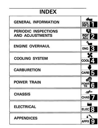
YALE G807 ERP20VT LIFT TRUCK (EUROPE) Service Repair Manualryurtt rftgy
This is the Highly Detailed factory service repair manual for theYALE G807 ERP20VT LIFT TRUCK, this Service Manual has detailed illustrations as well as step by step instructions,It is 100 percents complete and intact. they are specifically written for the do-it-yourself-er as well as the experienced mechanic.YALE G807 ERP20VT LIFT TRUCK Service Repair Workshop Manual provides step-by-step instructions based on the complete dis-assembly of the machine. It is this level of detail, along with hundreds of photos and illustrations, that guide the reader through each service and repair procedure. Complete download comes in pdf format which can work under all PC based windows operating system and Mac also, All pages are printable. Using this repair manual is an inexpensive way to keep your vehicle working properly.
Service Repair Manual Covers:
Frame
Operator's cab
Ac motor repair
Transaxle
Steering system
Brake system
Hydraulic system
Hydraulic cleanliness procedures
Main control valves
Cylinder repair (mast s/n a270-72, a551, a555, a559, a626, a627, a751-52,
B551, b555, b586-91, b749-54, c661-63, c665, d507-09, d515, d562-64, e509, e564)
Wire harness repair
User interface supervisor
User interface service technician
Electrical system
Industrial battery
Mast repair (s/n a270, a271, a272)
Mast repair (s/n c661, c662, c663, c665)
Metric and inch (sae) fasteners
Periodic maintenance
Capacities and specifications
Diagrams
Diagnostic troubleshooting manual
File Format: PDF
Compatible: All Versions of Windows & Mac
Language: English
Requirements: Adobe PDF Reader
NO waiting, Buy from responsible seller and get INSTANT DOWNLOAD, Without wasting your hard-owned money on uncertainty or surprise! All pages are is great to haveYALE G807 ERP20VT LIFT TRUCK Service Repair Workshop Manual.
Looking for some other Service Repair Manual,please check:
https://www.aservicemanualpdf.com/
Thanks for visiting!
YALE F879 GLC70VX LIFT TRUCK (EUROPE) Service Repair Manualryurtt rftgy
This is the Highly Detailed factory service repair manual for theYALE F879 GLC70VX LIFT TRUCK, this Service Manual has detailed illustrations as well as step by step instructions,It is 100 percents complete and intact. they are specifically written for the do-it-yourself-er as well as the experienced mechanic.YALE F879 GLC70VX LIFT TRUCK Service Repair Workshop Manual provides step-by-step instructions based on the complete dis-assembly of the machine. It is this level of detail, along with hundreds of photos and illustrations, that guide the reader through each service and repair procedure. Complete download comes in pdf format which can work under all PC based windows operating system and Mac also, All pages are printable. Using this repair manual is an inexpensive way to keep your vehicle working properly.
Service Repair Manual Covers:
Frame
Gm 4.3l v-6 engines
Kubota engine repair
Cooling system
Lpg fuel system gm 4.3l engine with psi
Three-speed powershift transmission repair
Transmission repair (dana spicer) 2x2
Drive axle and differential assembly repair (wet brake)
Steering axle
Brake system
Hydraulic gear pump
Hydraulic cleanliness procedures
Main control valve
Cylinder repair (mast s/n a513, a514, a613, a614, b513, b514)
High voltage switch (hvs) ignition
Wire harness repair
User interface
Electrical system
Mast repairs (s/n a513, a514, a613, a614, a702, a703, a704, a705, a706,
A707, a751, a752, b513, b514, b586, b587, b588, b589, b590, b591, b749, b750, b751, b752, b753, b754)
Metric and inch (sae) fasteners
Calibration procedures
Diagrams and schematics
Periodic maintenance
Capacities and specifications
Diagrams and schematics
Diagnostic troubleshooting manual
File Format: PDF
Compatible: All Versions of Windows & Mac
Language: English
Requirements: Adobe PDF Reader
NO waiting, Buy from responsible seller and get INSTANT DOWNLOAD, Without wasting your hard-owned money on uncertainty or surprise! All pages are is great to haveYALE F879 GLC70VX LIFT TRUCK Service Repair Workshop Manual.
Looking for some other Service Repair Manual,please check:
https://www.aservicemanualpdf.com/
Thanks for visiting!
YALE F818 GLC55VX LIFT TRUCK (EUROPE) Service Repair Manualryurtt rftgy
This is the Highly Detailed factory service repair manual for theYALE F818 GLC55VX LIFT TRUCK, this Service Manual has detailed illustrations as well as step by step instructions,It is 100 percents complete and intact. they are specifically written for the do-it-yourself-er as well as the experienced mechanic.YALE F818 GLC55VX LIFT TRUCK Service Repair Workshop Manual provides step-by-step instructions based on the complete dis-assembly of the machine. It is this level of detail, along with hundreds of photos and illustrations, that guide the reader through each service and repair procedure. Complete download comes in pdf format which can work under all PC based windows operating system and Mac also, All pages are printable. Using this repair manual is an inexpensive way to keep your vehicle working properly.
Service Repair Manual Covers:
Frame
Gm 4.3l v-6 engines
Cooling system
Lpg fuel system gm 4.3l engine with psi
1 and 2 sp ps transmission repair
Drive axle and differential assembly repair
Steering axle
Wet brakes - nmhg
Hydraulic gear pump
Hydraulic cleanliness procedures
Main control valve
Cylinder repair (mast s/n a551, a555, a559, a661, a662, a663, a66, b507,
B508, b509, b551, b555, b559, b562, b563, b564, b661, b662, b663, c515,
C551, c555, c559, d507, d508, d509, d515, d562, d563, d564, e509, and e564)
High voltage switch (hvs) ignition
Wire harness repair
User interface
Electrical system
Mast repairs (s/n a513, a514, a613, a614, a702, a703, a704, a705, a706,
A707, a751, a752, b513, b514, b586, b587, b588, b589, b590, b591, b749, b750, b751, b752, b753, b754)
Metric and inch (sae) fasteners
Calibration procedures
Diagrams and schematics
Periodic maintenance
Capacities and specifications
Diagrams and schematics
Diagnostic troubleshooting manual
File Format: PDF
Compatible: All Versions of Windows & Mac
Language: English
Requirements: Adobe PDF Reader
NO waiting, Buy from responsible seller and get INSTANT DOWNLOAD, Without wasting your hard-owned money on uncertainty or surprise! All pages are is great to haveYALE F818 GLC55VX LIFT TRUCK Service Repair Workshop Manual.
Looking for some other Service Repair Manual,please check:
https://www.aservicemanualpdf.com/
Thanks for visiting!
YALE E879 GLC60VX LIFT TRUCK Service Repair Manualryurtt rftgy
This is the Highly Detailed factory service repair manual for theYALE E879 GLC60VX LIFT TRUCK, this Service Manual has detailed illustrations as well as step by step instructions,It is 100 percents complete and intact. they are specifically written for the do-it-yourself-er as well as the experienced mechanic.YALE E879 GLC60VX LIFT TRUCK Service Repair Workshop Manual provides step-by-step instructions based on the complete dis-assembly of the machine. It is this level of detail, along with hundreds of photos and illustrations, that guide the reader through each service and repair procedure. Complete download comes in pdf format which can work under all PC based windows operating system and Mac also, All pages are printable. Using this repair manual is an inexpensive way to keep your vehicle working properly.
Service Repair Manual Covers:
Frame
Gm 4.3l v-6 engines
Kubota engine repair
Cooling system
Lpg fuel system gm 4.3l engine with psi
Three-speed powershift transmission repair
Transmission repair (dana spicer) 2x2
Drive axle and differential assembly repair (wet brake)
Steering axle
Brake system
Hydraulic gear pump
Hydraulic cleanliness procedures
Main control valve
Cylinder repair (mast s/n a513, a514, a613, a614, b513, b514)
High voltage switch (hvs) ignition
Wire harness repair
User interface
Electrical system
Mast repairs (s/n a513, a514, a613, a614, a702, a703, a704, a705, a706,
A707, a751, a752, b513, b514, b586, b587, b588, b589, b590, b591, b749, b750, b751, b752, b753, b754)
Metric and inch (sae) fasteners
Calibration procedures
Periodic maintenance
Capacities and specifications
Diagrams and schematics
Diagnostic troubleshooting manual
File Format: PDF
Compatible: All Versions of Windows & Mac
Language: English
Requirements: Adobe PDF Reader
NO waiting, Buy from responsible seller and get INSTANT DOWNLOAD, Without wasting your hard-owned money on uncertainty or surprise! All pages are is great to haveYALE E879 GLC60VX LIFT TRUCK Service Repair Workshop Manual.
Looking for some other Service Repair Manual,please check:
https://www.aservicemanualpdf.com/
Thanks for visiting!
Massey Ferguson MF 6260 Tractor Service Repair Manualryurtt rftgy
This is the Highly Detailed factory service repair manual for theMASSEY FERGUSON MF 6260 TRACTOR, this Service Manual has detailed illustrations as well as step by step instructions,It is 100 percents complete and intact. they are specifically written for the do-it-yourself-er as well as the experienced mechanic.MASSEY FERGUSON MF 6260 TRACTOR Service Repair Workshop Manual provides step-by-step instructions based on the complete dis-assembly of the machine. It is this level of detail, along with hundreds of photos and illustrations, that guide the reader through each service and repair procedure. Complete download comes in pdf format which can work under all PC based windows operating system and Mac also, All pages are printable. Using this repair manual is an inexpensive way to keep your vehicle working properly.
Service Repair Manual Covers:
Introduction
Splitting the Tractor
Engine
Clutch
Gearbox
Rear Axle
Power Take-Off
Front Axle
Hydraulics
Electrical Equipment
Electronics
Cab and Equipment
Accessories
Service Tools
File Format: PDF
Compatible: All Versions of Windows & Mac
Language: English
Requirements: Adobe PDF Reader
NO waiting, Buy from responsible seller and get INSTANT DOWNLOAD, Without wasting your hard-owned money on uncertainty or surprise! All pages are is great to haveMASSEY FERGUSON MF 6260 TRACTOR Service Repair Workshop Manual.
Looking for some other Service Repair Manual,please check:
https://www.aservicemanualpdf.com/
Thanks for visiting!
This is the Highly Detailed factory service repair manual for the2007 ARCTIC CAT 500 4X4 AUTOMATIC ATV, this Service Manual has detailed illustrations as well as step by step instructions,It is 100 percents complete and intact. they are specifically written for the do-it-yourself-er as well as the experienced mechanic.2007 ARCTIC CAT 500 4X4 AUTOMATIC ATV Service Repair Workshop Manual provides step-by-step instructions based on the complete dis-assembly of the machine. It is this level of detail, along with hundreds of photos and illustrations, that guide the reader through each service and repair procedure. Complete download comes in pdf format which can work under all PC based windows operating system and Mac also, All pages are printable. Using this repair manual is an inexpensive way to keep your vehicle working properly.
Service Repair Manual Covers:
General Information
Periodic Maintenance / Tune-Up
Engine / Transmission
Fuel / Lubrication / Cooling
Electrical System
Drive System
Suspension
Steering / Frame
Controls / Indicators
Aids for Maintenance
Troubleshooting
Wiring Diagrams
File Format: PDF
Compatible: All Versions of Windows & Mac
Language: English
Requirements: Adobe PDF Reader
NO waiting, Buy from responsible seller and get INSTANT DOWNLOAD, Without wasting your hard-owned money on uncertainty or surprise! All pages are is great to have2007 ARCTIC CAT 500 4X4 AUTOMATIC ATV Service Repair Workshop Manual.
Looking for some other Service Repair Manual,please check:
https://www.aservicemanualpdf.com/
Thanks for visiting!
Welcome to ASP Cranes, your trusted partner for crane solutions in Raipur, Chhattisgarh! With years of experience and a commitment to excellence, we offer a comprehensive range of crane services tailored to meet your lifting and material handling needs.
At ASP Cranes, we understand the importance of reliable and efficient crane operations in various industries, from construction and manufacturing to logistics and infrastructure development. That's why we strive to deliver top-notch solutions that enhance productivity, safety, and cost-effectiveness for our clients.
Our services include:
Crane Rental: Whether you need a crawler crane for heavy lifting or a hydraulic crane for versatile operations, we have a diverse fleet of well-maintained cranes available for rent. Our rental options are flexible and can be customized to suit your project requirements.
Crane Sales: Looking to invest in a crane for your business? We offer a wide selection of new and used cranes from leading manufacturers, ensuring you find the perfect equipment to match your needs and budget.
Crane Maintenance and Repair: To ensure optimal performance and safety, regular maintenance and timely repairs are essential for cranes. Our team of skilled technicians provides comprehensive maintenance and repair services to keep your equipment running smoothly and minimize downtime.
Crane Operator Training: Proper training is crucial for safe and efficient crane operation. We offer specialized training programs conducted by certified instructors to equip operators with the skills and knowledge they need to handle cranes effectively.
Custom Solutions: We understand that every project is unique, which is why we offer custom crane solutions tailored to your specific requirements. Whether you need modifications, attachments, or specialized equipment, we can design and implement solutions that meet your needs.
At ASP Cranes, customer satisfaction is our top priority. We are dedicated to delivering reliable, cost-effective, and innovative crane solutions that exceed expectations. Contact us today to learn more about our services and how we can support your project in Raipur, Chhattisgarh, and beyond. Let ASP Cranes be your trusted partner for all your crane needs!
What Could Be Behind Your Mercedes Sprinter's Power Loss on Uphill RoadsSprinter Gurus
Unlock the secrets behind your Mercedes Sprinter's uphill power loss with our comprehensive presentation. From fuel filter blockages to turbocharger troubles, we uncover the culprits and empower you to reclaim your vehicle's peak performance. Conquer every ascent with confidence and ensure a thrilling journey every time.
Implementing ELDs or Electronic Logging Devices is slowly but surely becoming the norm in fleet management. Why? Well, integrating ELDs and associated connected vehicle solutions like fleet tracking devices lets businesses and their in-house fleet managers reap several benefits. Check out the post below to learn more.
Ever been troubled by the blinking sign and didn’t know what to do?
Here’s a handy guide to dashboard symbols so that you’ll never be confused again!
Save them for later and save the trouble!
Understanding Catalytic Converter Theft:
What is a Catalytic Converter?: Learn about the function of catalytic converters in vehicles and why they are targeted by thieves.
Why are They Stolen?: Discover the valuable metals inside catalytic converters (such as platinum, palladium, and rhodium) that make them attractive to criminals.
Steps to Prevent Catalytic Converter Theft:
Parking Strategies: Tips on where and how to park your vehicle to reduce the risk of theft, such as parking in well-lit areas or secure garages.
Protective Devices: Overview of various anti-theft devices available, including catalytic converter locks, shields, and alarms.
Etching and Marking: The benefits of etching your vehicle’s VIN on the catalytic converter or using a catalytic converter marking kit to make it traceable and less appealing to thieves.
Surveillance and Monitoring: Recommendations for using security cameras and motion-sensor lights to deter thieves.
Statistics and Insights:
Theft Rates by Borough: Analysis of data to determine which borough in NYC experiences the highest rate of catalytic converter thefts.
Recent Trends: Current trends and patterns in catalytic converter thefts to help you stay aware of emerging hotspots and tactics used by thieves.
Benefits of This Presentation:
Awareness: Increase your awareness about catalytic converter theft and its impact on vehicle owners.
Practical Tips: Gain actionable insights and tips to effectively prevent catalytic converter theft.
Local Insights: Understand the specific risks in different NYC boroughs, helping you take targeted preventive measures.
This presentation aims to equip you with the knowledge and tools needed to protect your vehicle from catalytic converter theft, ensuring you are prepared and proactive in safeguarding your property.
Expanding Access to Affordable At-Home EV Charging by Vanessa WarheitForth
Vanessa Warheit, Co-Founder of EV Charging for All, gave this presentation at the Forth Addressing The Challenges of Charging at Multi-Family Housing webinar on June 11, 2024.
EV Charging at MFH Properties by Whitaker JamiesonForth
Whitaker Jamieson, Senior Specialist at Forth, gave this presentation at the Forth Addressing The Challenges of Charging at Multi-Family Housing webinar on June 11, 2024.
2. CHAPTER 1.
GENERAL INFORMATION
MACHINE IDENTIFICATION ..................................... 1-1
FRAME SERIAL NUMBER .................................... 1-1
ENGINE SERIAL NUMBER.................................... 1-1
STORAGE .................................................... 1-2
PRE-SEASON PREPARATION .................................... 1-2
IMPORTANT INFORMATION..................................... 1-3
NO FLAME SOURCES ........................................ 1-3
WASHING AND CLEANING ................................... 1-3
RIGHT TOOLS.............................................. 1-3
MAKING IT NEAT........................................... 1-3
TIGHTENING TORQUE ...................................... 1-3
ALL REPLACEMENT PARTS .................................. 1-4
GASKETS, OIL SEALS, AND O-RINGS .......................... 1-4
LOCK WASHERS/PLATES AND COTTER PINS.................... 1-4
BEARINGS AND OIL SEALS ............... " ................. 1-4
Cl RCLIPS ..................... ',' ........................... 1-5
NOTES ON DISASSEMBLY AND ASSEMBLY ..................... 1-5
SPECIAL TOOLS ............................................... 1-6
FOR TUNE UP .............................................. 1-6
FOR ENGINE SERVICE ...................................... 1-6
FOR POWER TRAIN SERViCE ................................. 1-7
FOR ELECTRICAL SERVICE .................................. 1-8
3. 1·1
GENERAL
INFORMATION
MACHINE IDENTIFICATION
FRAME SERIAL NUMBER
The frame serial number CD is located on the
right-hand side of the frame (just below the
front of the seat).
ENGINE SERIAL NUMBER
The engine serial number CD is located on the
right-hand side of the crankcase.
NOTE: _________________________
The first three digits of these numbers are for
model identifications; the remaining digits are
the unit production number.
Starting Serial Number
82M·000101
NOTE: _________________________
Designs and specifications are subject to change
without notice.
4. STORAGE/PRE-SEASON PREPARATION I~~~I~I
STORAGE
If a snowmobile will not be used for several
months, it should be stored in a proper place so
that both the engine and the track are not
damaged.
• Completely drain the fuel tank, and disconnect
the fuel line from the carburetor.
• With the engine running at idle, squirt oil into
the carburetor until the engine dies. This will
distribute oil evenly throughout the engine,
and protect it against rust.
• Disassemble the suspension, clean and grease
all parts, and reassemble the suspension.
• Lightly coat all shafts and axles with grease.
• Oil all fittings and cable controls with a lightly
oiled cloth.
• Loosen the track.
• Block the chassis so that the track is off the
floor.
• Protect the snowmobile with a covering.
PRE-SEASON PREPARATION
Perform the predelivery service as described in
the predelivery check list before operating any
snowmobile that has been stored for several
months. (Refer to CHAPTER 2. "PERIODIC
MAINTENANCE TABLE", page 2-1.)
1-2
5. 1-3
IMPORTANT INFORMATION
PREPARATION FOR REMOVAL AND DIS-
ASSEMBLY
1. Remove all dirt, mud, dust, and foreign
material before removal and disassembly.
While cleaning, take care to protect the
electrical parts, such as relays, switches,
motor, resistors, controllers, etc., from
high pressure water splashes.
2. Use proper tools and cleaning equipment.
Refer to "SPECIAL TOOLS".
3. When disassembling the machine, keep
mated parts together. This includes gears,
cylinders, pistons, and other mated parts
that have been "mated" through normal
wear. Mated parts must be reused as an
assembly or replaced.
4. During the machines disassembly, clean all
parts and place them in trays in the order of
disassembly. This will speed up assembly
time and help assure that all parts are
correctly reinstalled.
5. Keep away from fire.
6. Be sure to keep to tightening torque specifi-
cations. When tightening bolts, nuts, and
screws, start with a larger-diameter one and
from an inner-positioned one to an outer-
positioned one in a criss-cross pattern.
6. IMPORTANTlNFORMATION 1tm:~I-1
ALL REPLACEMENT PARTS
300-000
300-002
300-003
1. We recommend to use Yamaha genuine parts
for all replacements. Use oil and/or grease
recommended by Yamaha for assembly and
adjustment.
GASKETS, OIL SEALS, AND a-RINGS
1. All gaskets, seals, and a-rings should be re-
placed when an engine is overhauled. All
gasket surfaces, oil seal lips, and a-rings
must be cleaned.
2. Properly oil all mating parts and bearings
during reassembly. Apply grease to the oil
seal lips.
LOCK WASHERS/PLATES AND COTTER
PINS
1. All lock washers/plates CD and cotter pins
must be replaced when they are removed.
Lock tab(s) should be bent along the bolt or
nut flat(s) after the bolt or nut has been pro-
perly tightened.
BEARINGS AND OIL SEALS
1. Install the bearing(s) CD and oil seaJ(s) ®
with their manufacturer's marks or numbers
facing outward. (In other words, the
stamped letters must be on the side exposed
to view.) When installing oil seaJ(s), apply a
light coating of light-weight lithium base
grease to the seallip(s). Oil the bearings libe-
rally when installing.
Do not use compressed air to spin the bearings
dry. This causes damage to the bearing surfaces.
'-4
D
7. SPECIAL TOOLS
300-001
1-5
CIRCLlPS
1. All circlips should be inspected carefully be-
fore reassembly. Always replace piston pin
clips after one use. Replace distorted cir-
clips. When installing a circlip CD , make sure
that the sharp edged corner 00 is positioned
opposite to the thrust @ it receives. See the
sectional view.
@Shaft
SPECIAL TOOLS
The proper special tools are necessary for com-
plete and accurate tune-up and assembly. Using
the correct special tool will help prevent damage
caused by the use of improper tools or impro-
vised techniques.
FOR TUNE UP
1. Vacuum Gauge
PIN Y U-08030
This gauge is used for carburetor synchroniza-
tion.
2. Sheave Gauge
PIN YS-91 047
This gauge is used for sheave distance and offset
adjustment.
3. Dial Gauge
PIN Y U-03097
This gauge is used for ignition timing adjust-
ment.
8. SPECIAL TOOLS
4. Dial Gauge Stand Set
PIN YU-01256
These tools are used for ignition timing adjust-
ment.
FOR ENGINE SERVICE
1. Universal Clutch Holder
PIN YM-91042
This tool is used to hold starter pulley.
2. Piston Pin Puller
PIN YU-01304
This tool is used to remove piston pin.
3. Universal Rotor Holder
PIN YU-01235
This tool is used to hold CD I magneto.
4. Rotor Puller
PIN YU-33270
This tool is used to remove COl magneto.
1-6
9. SPECIAL TOOLS
1-7
5_ Cooling System Tester
PIN YU-22460-01
This tester is used for checking cooling system.
FOR POWER TRAIN SERVICE
1. Primary Sheave Holder
PIN YS-01880
This tool is used to hold primary sheave.
2. Primary Shave Puller
PIN YS-01882-A
This tool is used for removing primary sheave.
3. Sheave Compressor
PIN YS-28891
This tool is used for disassembling and assembl-
ing sheave.
4. Clutch Spider Separator
PIN YS-28890-A
These tools are used for disassembling and
assembling primary sheave.
10. SPECIAL TOOLS I~IJ:~I-
5. Clutch Separator Adapter
PIN YS-34480
This tool is used for disassembling and assembl-
ing primary sheave.
6. Track Clip Installer
PIN YS-91045
This tool is used for installing the track clip.
FOR ELECTRICAL SERVICE
1. Pocket Tester
PIN YU-03112
This instrument is necessary for checking the
electrical components.
2. Electro Tester
PIN Y U-33260
This instrument is invaluable for checking the
electrical system.
1-8
13. I~ IQ IINTRODUCTION/PERIODIC MAINTENANCE TABLE
PERIODIC INSPECTIONS AND ADJUSTMENTS
INTRODUCTION
This chapter includes all information necessary to perform recommended inspections and adjustments.
These preventive maintenance procedures, if followed, will ensure more reliable vehicle operation and
a longer service life. The need for costly overhaul work will be greatly reduced. This information
applies to vehicles already in service as well as new vehicles that are being prepared for sale. All service
technicians should be familiar with this entire chapter.
PERIODIC MAINTENANCE TABLE
Every
Check point 20 hrs. or 40 hrs. or 80 hrs. or When
Seasonally
400 km 800 km 1,600 km necessary
(250 mj) (500 mj) (1,000 mi)
ENGINE:
Tightness of bolts and nuts 0
Bends, cracks and wear 0
Abnormal noise 0
Loose connection and breaks of fuel and pulser hoses 0
Loose connection and breaks of oil pipes 0
Loose connection and breaks of oil delivery pipe 0
Manual rope starter system 0
Carburetor:
Operation of starter jet 0
Mixing adjuster (pilot screw) 0
Idling speed adjustment 0
Throttle valve synchronization 0 0
Operation and adjustment of oil pump 0
Ignition timing 0
Engine compression 0
Cylinder head/exhaust pipe decarbonization 0
Spark plug condition, gap and cleaning 0
Tightening of the cylinder head**
Coolant leakage 0 0
Operation of water pump and fuel pump 0 0
Water pump drive belt tension/damage 0 0
Coolant level 0 0
DRIVE:
Tightness of bolts and nuts 0
Wear on slide runners 0
Primary drive system 0
V-belt 0
Secondary drive system 0
Sheave distance 0
Sheave offset 0
Brake pad wear 0
Brake operation and adjustment 0
Guide wheel rubber 0
Wear of drive track wheel sprocket 0
2-1
14. INTRODUCTJONIPERIODIC MAINTENANCE TABLE I~IfillI
Every
Check point 20 hrs. or 40 hrs. or 80 hrs. or When
Seasonally
400 km 800 km 1,600 km necessary
(250 mj) (500 mj) (1,000 mi)
Drive track adjustment 0
Breaks in drive track 0
,
Bends in front and rear axles 0
Checking of lock washers 0
Drive cha:n adjustment 0
Drive chain oil level 0
BODY:
Tightness of bolts and nuts 0
Bends and cracks 0
Welded/riveted, joints 0
Ski adjustment 0
Breaks in fuel tank 0
Cleaning of fuel tank 0
Fuel filter 0
Loose connection and breaks in fuel pipe 0
Breaks in oil tank 0
Oil filter 0
ELECTRICAL:
Wear, breakage of wire covering 0
Breaks in high·tension cord 0
Voltage regulator workil)g voltage 0
Operation of engine stop switch 0
Operation of throttle override system 0 0
Headlight 0
Taillight 0
Brake light 0
** Retighten every 10 hours from the first use.
2·2
15. LUBRICATION INTERVALS
LUBRICATION INTERVALS
Every
lubrication point 20 hrs. or 40 hrs. or 80 hrs. or When
Seasonally
Oil/Grease
400 km 800 km 1,600 km necessary Brand name
(250 mj) (500 mi) (1,000 mi)
ENGINE:
Recoil starter case 0
Starter plunger 0
Aeroshell grease #7A or
Esso Beacon 325 grease
Oil pump plunger 0
Engine oil tank 0
YAMAlUBE2
or equivalent
DRIVE:
Secondary shaft and
0
Molybdenum disulfide
sliding sheave snowmobile grease
Shaft 1 and shaft 2
0
light weight lithium
(Slide rail) soap base grease
Drive chain oil
0
Gear oil API Gl-3
replacement SAE #75 or #80
CHASSIS:
Steering column lower
0
light weight lithium
bearing soap base grease
Steering column upper
0 Motor oilbearing
Steering links 0
Brake wire end stopper
0 0 Esso Beacon 325 greaseand brake lever
Telescopic strut
or Aerosell grease
0 #7A
suspension
Stabilizer slider 0
2-3
16. SHROUD OPENING/SIDE COWL I~IfillCOWLS, COVERS, SEAT AND
HANDLEBAR
SHROUD OPENING
When the engine requires a check or service, the
shroud can be opened forward.
1. Unhook:
• Shroud latches <D
Right and left of the shroud.
2. Should be slowly raised until shroud stops.
SIDE COWL
Removal
1. Open the shroud.
Refer to the "SHROUD OPENING" section.
2. Remove:
.Screws <D
3. Open the side cowl and remove it.
.1 4. Remove:
• Bracket <D
2-4
18. HANDLEBAR COVER, HEADLIGHT AND METER ASSEMBLY Ir8fItitI2. Disconnect:
• Tail/Brake light leads
Installation
Reverse the removal procedure.
Note the following points.
1. Install:
• Seat
Screws (Seat - Front):
3 Nm (0.3 m· kg, 2.2 ft·lb)
........... Nuts (Seat - Rear):
9 Nm (0.9 m· kg, 6.5 ft·lb)
HANDLEBAR COVER, HEADLIGHT AND
METER ASSEMBLY
Removal
1. Remove:
• Handlebar cover (Rear) CD
2. Remove:
• Handlebar cover (Front) CD
3. Remove:
• Meter cover CD
2-6
19. 1~14it1_H_A_ND_L_EB_A_R_______________________
2-7
4. Disconnect:
• Meter leads
• Speedometer cable
5. Remove:
• Front cowl
6. Remove:
• Headlight
• Meter assembly
Installation
Reverse the removal procedure.
Note the following points.
1. Install:
• Front cowl
Screw (Front cowl):
3 Nm (0.3 m· kg, 2.2 ft·lb)
HANDLEBAR
Removal
1. Remove:
• Handlebar covers
• Meter assembly
• Headlight
Refer to the "HANDLEBAR COVER,
HEADLIGHT AND METER ASSEMBLY"
section.
20. ________________________H_A_ND_L_EB_A_Rlrgfl4il1
2. Open the shroud.
Refer to the "SHROUD OPENING" section.
3. Disconnect:
• Handlebar switch leads
4. Unhook the throttle cable holder CD and
remove the throttle cable end from the
throttle lever.
5. Remove:
• Brake cable
Removal steps:
• Loosen the locknut CD
• Turn in the adjuster <ID
• Remove the brake cable end from the brake
lever.
6. Remove:
.Band CD
7. Remove:
• Handlebar
• Upper handlebar holders
• Lower handlebar holder
2-8
21. IrgsIQ ICOVERS
_r--.....J-1 b
T
2-9
Installation
Reverse the removal procedure.
Note the following points.
1. Instal/:
eHandlebar
e Lower handlebar holder
e Upper handlebar holders
NOTE:__________________________
eThe upper handlebar holder should be installed
with the punch mark CD forward.
eAlign the punch marks CV with the handlebar
holder gaps respectively.
eTighten the bolts to specification so that
the front clearance "a" is smaller than rear
clearance "b".
Bolts (Handlebar holder):
15 Nm (1.5 m'kg, 11 ft·lb)
First tighten the bolts on the front side of the
handlebar holder, and then tighten the bolts
on the rear side.
2. Adjust:
e Brake
Refer to "BRAKE ADJUSTMENT" sec-
tion.
COVERS
Removal
1. Open the shroud.
Refer to the "SHROUD OPENING" section.
2. Open the side cowls.
22. ________________________C_O_VE_R_sl~I4il1
3. Remove:
• Screw (Seat - Front)
4. Remove:
• Handlebar cover
• Headlight
• Meter assembly
Refer to the "HANDLEBAR COVER,
HEADLIGHT AND METER ASSEMBLY"
section.
5. Remove:
.Handlebar
Refer to the "HANDLEBAR" section.
6. Remove:
• Side cover (Left) CD
7. Remove:
• Main switch holding nut CD
."STARTER" lever holding nut CV
• Decompression lever holding nut @
8. Remove:
.Cover (Center) CD
2-10
23. Ir8fI~ICOVERS
2-11
9. Disconnect:
eOil pipe CD
eFuel pipe CID
eGauge light leads @
NOTE: __________________________
Plug the oil pipe and fuel pipe so that the oil
and fuel will not run out of each tanks.
10. Remove:
eCover (Right) CD
Installation
Reverse the removal procedure.
Note the following points.
1. Install:
eCover (Right and left)
NOTE:__________________________
Mate the projections on the covers (R ight and
left) with the corresponding holes in the cover
(Center).
2. Install:
eOil pipe CD
eFuel pipe CID
NOTE: ________________________
Install the oil pipe and the fuel pipe to the cover
(Right).
Refer to the "CHAPTER 9 - CABLE ROUT-
ING" section.
24. _________________E_N_G_IN_E_O_I_L_L_EV_E_L_I_N_SP_E_C_T_IO_N_I IIANDSJPI~ICOOLANT LEVEL INSPECTION . . ~ .
ENGINE
ENGINE OIL LEVEL INSPECTION
1. Place the machine on a level place.
2. Inspect:
• Engine oil level
Oil level low ~ Add sufficient oil.
CD "F" (Full) level mark
® "E" (Empty) level mark
3. Open the shroud.
Refer to the "SHROUD OPENING" section.
4. Add the engine oil until the oil level reaches
"F" level mark.
~ Recommended oil:
·U YAMALUBE "2" or equivalent
CD Oil tank cap
Always use the same type of engine oil; mixing
oils may result in a hurmful chemical reaction
and lead to poor performance.
COOLANT LEVEL INSPECTION
1. Place the machine on a level place.
2. Start the engine and let it warm up.
3. Stop the engine.
2·12
25. I IANDSJPI.I_~~~~~~~~_ _~ _ COOLANT REPLACEMENT
2-13
4. Open the shroud.
Refer to the "SHROUD OPENING" section.
5. Open the side cowl (R ight) CD
6. Inspect:
• Coolant level
Coolant level is under "LOW" level mark
CD ~ Add top water.
7. Add the top water (Soft water) until the
coolant level reaches "FULL" level mark CID.
• Hard water or salt water is harmful to the
engine parts; use boiled or distilled water if
you can't get soft water.
• Do not use water containing impurities or oil.
@ Reservoir tank cap
COOLANT REPLACEMENT
NOTE: __________________________
The coolant should be changed at last seasonally.
1. Place the machine on a level place.
2. Open the shroud.
Refer to the "SHROUD OPENING" section.
3. Remove:
.Side cowls
Refer to the "SI DE COWL" section.
26. _~~~~~~~~liANDSJPI.1COOLANT REPLACEMENT . . ~ .
4. Remove:
• Muffler CD
5. Remove:
• Exhaust pipe CD
6. Remove:
• Seat
Refer to the "SEAT" section.
7. Remove:
.Coolant filler cap CD
WARNING:
Do not remove the coolant filler cap CD especial-
ly when the engine is hot. Scalding hot fluid and
steam may be blown out under pressure, which
could cause serious injury. When the engine has
cooled, place thick rag like a towel over the
radiator cap, slowly rotate the cap counter-
clockwise to the detent. This procedure allows
any residual pressure to escape. When the hissing
sound has stopped, press down on the cap while
turning counterclockwise and remove it.
8. Place an open container under the drain
bolts CD.
9. Remove:
• Drain bolts
2·14
27. I IANDSJPlel_~~~~~~~~. . ~. COOLANT REPLACEMENT
2·15
10. Drain the coolant.
NOTE:___________________________
When draining the coolant completely, lift up
the tail of the machine.
• When coolant splashes to your eye;
Thoroughly wash your eye with water and see
your doctor.
• When coolant splashes to your clothes;
Quickly wash it away with water and then
with soap.
• When coolant is swallowed;
Quickly make him vomit and take him to a
doctor.
11. Remove the reservoir tank CD and drain the
coolant;
12. Install:
• Reservoir tank
13. Inspect:
• Gasket (Drain bolt)
Damage""* Replace.
14. Install:
• Gaskets
• Drain bolts
• Exhaust pipe
• Muffler
Drain Bolt:
32 Nm (3.2 m'kg, 23 ft·lb)
Bolts (Exhaust pipe):
10 Nm (1.0 m'kg, 7.2 ft·lb)
28. COOLANT REPLACEMENT
15. Fill:
.Cooling system
Recommended Coolant:
High Quality Ethylene Glycol
Anti-freeze Containing
Anti-corrosion for
Aluminum Engine Inhibitors
Coolant and Water Mixed Ratio:
60% :40%
Total Amount:
4.2 L (3.7 Imp qt, 4.4 US qt)
Reservoir Tank Capacity:
0.25 L (0.22 Imp qt, 0.26 US qt)
• Hard water or salt water is harmful to the
engine parts; use boiled or distilled water if
you can't get soft water.
• Do not use water containing impurities or oil.
Coolant filling steps:
• Fill the coolant into the conduit.
• Loosen the bleed bolt CD of heat exchanger.
• Keep the coolant running out until air
bubbles disappear.
• Tighten the bleed bolt.
Bleed Bolt:
6 Nm (0.6 m' kg, 4.3 ft·lb)
• Fill the coolant again into the conduit.
• Loosen the bleed bolt CID of cylinder head.
• Keep the coolant running out until air
bubbles disappear.
• Tighten the bleed bolt.
Bleed Bolt:
6 Nm (0.6 m'kg, 4.3 ft·lb)
2-16
29. 2-17
COOLING SYSTEM INSPECTION
- Fill the coolant into the conduit to specified
level CD.
- With the track off the ground, run the
engine at 4,000 rpm until the thermostat
opens and the coolant freely circulates.
If the coolant level decreases in the filler
pipe, with the engine running, add coolant
until the level is once again at the top of
the filler neck, and install the cap.
WARNING:
Avoid contact with the moving track. En-
tanglement in the machinery of shop towels,
clothing, or body parts could result in
serious injury.
- Fill the coolant again into the conduit to
specified level.
-I nstall the filler cap.
- Fill the coolant into the reservoir tank until
the coolant level reaches "FULL" level mark
CV·
16. Inspect:
- Cooling system
Coolant leakage -+ Repair.
17. Install:
-Seat
Refer to the "SEAT" section.
18. Install:
-Side cowls
Refer to the "SI DE COWL" section.
COOLING SYSTEM INSPECTION
1. Open the shroud.
Refer to the "SHROUD OPENING" section.
2. Remove:
-Seat
Refer to the "SEAT" section.
30. FUEL LINE INSPECTION/ENGINE OIL LINE INSPECTION/ I~ I~ IENGINE IDLE SPEED ADJUSTMENT . . ~ _
3. Inspect:
• Hoses
Crack/Damage ~ Replace.
• Heat exchanger
Crack/Damage ~ Replace.
Refer to the "CHAPTER 4 - COOLING
SYSTEM" for replacement.
4. Install:
.Seat
Refer to the "SEAT" section.
FUEL LINE INSPECTION
1. Open the shroud.
Refer to the "SHROUD OPENING" section.
2. Inspect:
• Fuel hose
Crack/Damage ~ Replace.
ENGINE OIL LINE INSPECTION
1. Open the shroud.
Refer to the "SHROUD OPENING" section.
2. Inspect:
• Engine oil hose
Crack/Damage ~ Replace.
ENGINE IDLE SPEED ADJUSTMENT
1. Open the shroud.
Refer to the "SH ROUD OPEN ING" section.
2·18
31. 2-19
THROTTLE CABLE FREE PLAY ADJUSTMENT
2_ Adjust:
-Pilot screw CD
Pilot screw adjustment steps:
-Turn in the both pilot screw until they are
lightly seated.
-Turn out the both pilot screw to specifica-
tion.
Pilot Screw:
5/8 turns out
3. Start the engine and let it warm up.
4. Adjust:
- Engine idle speed
Adjustment steps:
- Turn the throttle stop screw CD in or out
until the specified engine speed is obtained.
Turn in Idle speed becomes higher.
Turn out Idle speed becomes lower.
C Engine Idle Speed:
1,400 - 1,600 rlmin
NOTE:
After adjusting the engine idle speed, the
throttle cable free play should be adjusted.
THROTTLE CABLE FREE PLAY ADJUST-
MENT
NOTE:_____________
Before adjusting the throttle cable free play,
the engine idle speed should be adjusted.
32. CARBURETOR SYNCHRONIZATION I~IjiiI
1. Measure:
• Throttle cable free play ®
Out of specification -? Adjust.
Throttle Cable Free Play:
1.0 '" 2.0 mm (0.04 '" 0.08 in)
2. Adjust:
• Throttle cable free play
Free play adjustment steps:
• Open the shroud.
Refer to the "SHROUD OPENING" section.
• Loosen the locknut CD .
• Turn the adjuster @ in or out until the
specified free play is obtained.
Turn in Free play is increased.
Turn out Free play is decreased.
• Tighten the locknut.
CARBURETOR SYNCHRONIZATION
1. Open the shroud.
Refer to "SHROUD OPENING" section.
2. Remove:
.Plugs CD
3. Attach:
• Vacuum Gauge (YU-08030) CD to the
vacuum plugs.
4. Start the engine and let it warm up.
WARNING:
Do not move the throttle lever more than
necessary so that the engine will not run faster
than the following revolutions at which the
snowmobiles starts to more off.
Engine revolutions: 3,000 r/min
2-20
33. IlANOSJP I~I_________. . ~. CARBURETOR SYNCHRONIZATION
2·21
5. Adjust:
• Engine idle speed
Refer to the "ENGINE IDLE SPEED
ADJUSTMENT" section.
Engine Idle Speed:
1,400""" 1,600 r/min
6. Adjust:
• Carburetor synchronization
Carburetor synchronization adjustment steps:
• Turn the synchronizing screw CD in or out
until both gauges read the same.
7. Check:
• Engine idle speed
Out of specification -+ Adjust.
Idle speed adjustment steps:
• Turn the throttle stop screw CD in or out
until specified idle speed is obtained.
Turn in Idle speed becomes higher.
Turn out Idle speed becomes lower.
NOTE:
Do not adjust the pilot screws.
34. 2·23
DECOMPRESSION CABLE ADJUSTMENT
1. Open the shroud.
Refer to the "SHROUD OPENING" section.
2. Pull the outer tube of decompression cable
upward.
3. Check:
• Decompression cable free play ®
Out of specification ~ Adjust.
Free Play:
0.5 '" 1.5 mm (0.02 '" 0.06 in)
4. Adjust:
• Decompression cable free play
Free play adjustment steps:
• Remove the rubber caps CD.
• Loosen the locknut CID •
• Turn the adjuster @ in or out until the
specified free play is obtained.
Turn in Free play is increased.
Turn out Free play is decreased•
• Tighten the locknut and install the both
rubber cap.
5. Close the shroud.
35. OIL PUMP CABLE FREE PLAY ADJUSTMENT ImrIQ IOIL PUMP CABLE FREE PLAY ADJUST-
MENT
NOTE:_____________
Before adjusting the oil pump cable free play,
the throttle cable free play should be adjusted.
1. Open the shroud.
Refer to the "SHROUD OPENING"
section.
2. Remove:
• Rubber cap CD
3. Pull:
• Oil pump outer cable
4. Measure:
• Oil pump cable free play ®
Out of specification -+ Adjust.
~ Free Play:
24 - 26 mm (0.94 - 1.02 inl
5. Adjust:
• Oil pump cable free play
Free play adjustment steps:
• Loosen the locknut CD .
• Turn the adjuster ® in or out until the
specified free play is obtained.
Turn in Free play is increased.
Turn out Free play is decreased•
• Tighten the locknut and install the rubber
cap.
6. Close the shroud.
I
2-24
36. IrcrIQIOIL PUMP STROKE ADJUSTMENT
It
2-25
OIL PUMP STROKE ADJUSTMENT
1. Open the shroud and side cowl (Left).
2. Remove:
• Drive V-belt guard CD
3. Remove:
• Blind cover CD
4. Remove:
• Bolts (I ntake silencer)
5. Loosen:
.Screws (Carburetor joints)
6. Remove:
• Carburetors
NOTE:_____________
The throttle cable, starter cables and carburetor
switch leads do not need removing.
37. _~~~~~~~~_IIANDSJPI_IOIL PUMP STROKE ADJUSTMENT . . ~ .
7. Disconnect:
• Fuel hoses CD
NOTE:___________________________
Plug the fuel hoses so that fuel does not run out.
8. Loosen:
• Locknut CD (Oil pump cable)
9. Remove:
.Adjuster CD (Oil pump cable)
• Oil pump cable ®
10. Disconnect:
.Oil hoses CD
.Oil delivery hoses ®
NOTE: __________________________
Plug the oil hoses and oil delivery hoses so that
oil does not run out.
11. Place a rug under the oil pump assembly.
12. Remove:
• Oil pump assembly CD
2·26
38. liANDSJPlel_~~~~~~~~. . ~. OIL PUMP STROKE ADJUSTMENT
®~®
@ 5
2·27
13. Remove:
eOil pump cover CD
14. Wipe off the grease from the plunger top.
15. Measure:
eMinimum pump stroke ®
Out of specification -+ Adjust.
Minimum Pump Stroke:
0.15 - 0.20 mm (0.006 - 0.008 in)
Minimum pump stroke measurement steps:
eTurn the pump worm gear CD with your
fingers, until the plunger top ® is at its
maximum distance from the pump body
mating surface @ of the pump cover.
e Using a Feeler Gauge, measure the minimum
pump stroke ® between the adjusting plate
@ and the raised boss @ on the adjusting
pulley.
. elf minimum pump stroke is not within the
specified limits, perform the adjustment
steps.
16. Measure:
eMaximum pump stroke @
Out of specification -+ Adjust.
Maximum Pump Stroke:
1.62 - 1.80 mm (0.064 - 0.071 in)
Maximum pump stroke measurement steps:
ePull the oil pump cable CD out of its sheather
as far as it will go. The cable must be held in
this taut position when measuring the
maximum pump stroke.
NOTE: _______________________
It may be helpful to securely warp duct tape
® around the cable where it enters the
sheath.
39. OIL PUMP STROKE ADJUSTMENT 1mr1G.I
• Turn the pump worm gear @ with your
fingers, until the plunger top @ is at its
maximum distance from the pump body <ID.
• Using a Feeler Gauge, measure the maxi-
mum pump stroke @ .
• If maximum pump stroke is not within the
specified limits, perform the adjustment
steps.
17. Adjust:
• Oil pump stroke
Adjustment steps:
• Remove the locknut ill , spring washer CV
and adjusting plate @ .
• Adjust the pump stroke by adding or remov-
ing a shim.
Add shim Pump stroke is increased.
Remove shim Pump stroke is decreased.
• Reinstall the adjusting plate, spring washer
and locknut.
I® Locknut:
7 Nm (0.7 m·kg, 5.1 ft·lb)
• Recheck the minimum and maximum pump
stroke..
If out of specification limits, perform the
above steps again.
18. Apply:
• Lithium soap base grease
To out side of pump pulley.
2-28
40. I IANDSJPIBI_~~~~~~~~. . ~ _ OIL PUMP STROKE ADJUSTMENT
2·29
19. Install:
• Oil pump cover
NOTE:_____________
Apply the Yamabond No. 5® (ACC-11001-31-
00) to the mating surface of the oil pump cover.
20. Tighten:
.Screws (Oil pump cover)
Screws (Oil pump cover):
2 Nm (0.2 m° kg, 1.4 ftolb)
21. Inspect:
• Gasket (Oil pump)
Damage ~ Replace.
22. Install:
• Oil pump assembly
Bolts (Oil pump assembly):
4 Nm (0.4 mokg, 2.9 ftolb)
NOTE: ______________
After installing the oil pump assembly, the oil
pump, oil hose and oil delivery hose should be
bleed.
Refer to the "01 L PUMP AI R BLEEDING"
section.
41. OIL PUMP AIR BLEEDING
23. Install:
• Oil pump cable
.Oil hoses
• Oil delivery hoses
• Fuel hoses
• Carburetors
• Bolts (Intake silencer)
• Blind cover
• Drive V-belt guard
24. Adjust:
.Oil pump cable free play
Free Play:
24'" 26 mm (0.94'" 1.02 in)
Refer to the "01 L PUMP CABLE FREE
PLAY ADJUSTMENT" section.
25. Close the side cowl (Left) and shroud.
OIL PUMP AIR BLEEDING
The oil pump and delivery line must be bled on
the following occasions:
• Any portion of the oil system has been dis-
connected.
• The machine has been turned on its side.
• Whenever the oil tank has been run empty.
• During predelivery.
1. Open the shroud and side cowl (Left).
2. Remove:
• Drive V-belt guard CD
2-30
42. I~IQI
2-31
OIL PUMP AIR BLEEDING
3. Remove:
• Blind cover ill
4. Remove:
• Bolts (Intake silencer)
5. Loosen:
.Screws (Carburetor joints)
6. Remove:
• Carburetors
NOTE:__________________________
The throttle cable, starter cables and carburetor
switch leads do not need removing.
7. Disconnect:
• Fuel hoses ill
NOTE:__________________________
Plug the fuel hoses so that fuel does not run out
of the fuel pump.
43. OIL PUMP AIR BLEEDING ImrIQ I8. Loosen:
• Locknut CD (Oil pump cable)
9. Remove:
.Adjuster CD (Oil pump cable)
• Oil pump cable ®
10. Disconnect:
• Oil hoses CD
.Oil delivery hoses ®
11. Place a rug under the oil pump assembly.
12. Fill:
.Oil tank
Recommended Oil:
Yamalube "2" or equivalent
2-32
44. 2-33
OIL PUMP AIR BLEEDING
13. Connect:
.Oil hoses
NOTE: __________________________
Make sure that the oil hoses are completly bleed
of air. Then, connect them with the oil pump.
14. Put Yamalube "2" or equivalent into the oil
delivery hoses for complete air bleeding.
Then, connect them with the oil pump.
15. Remove:
• Bleed screw CD
16. Inspect:
• Gasket (Bleed screw)
Damage ~ Replace.
17. Keep the oil running out until air bubbles
disappear.
18. Install:
• Gasket (Bleed screw)
• Bleed screw
19. Connect:
• Fuel hoses
45. _~~~~~~~~.IIANDSJPlelOIL FILTER INSPECTION. . ~.
20. Install:
• Carburetors
• Bolts (I ntake silencer)
• Blind cover
• Drive V-belt guard
21. Start the engine and keep it running at idle
for two minutes or so.
NOTE:__________________________
Pull the oil pump cable all the way out to set
the oil pump stroke to a maximum.
22. Close the side cowl (Left) and shroud.
OIL FILTER INSPECTION
1. Open the shroud.
2. Remove:
• Oil tank stay CD
3. Disconnect:
.Oil hoses
NOTE: __________________________
Plug the oil hoses so that the oil will not run
out of the oil tank and oil pump.
2·34
46. 11
2-35
FUEL FILTER INSPECTION
11
4_ Inspect:
-Oil filter CD
Contamination -+ Replace.
Recommended replacement interval:
Every season
5. Install:
-Oil filter
6. Connect:
-Oil hoses
7. Install:
-Oil tank stay
Bolts (Oil tank stay):
7 Nm (0.7 m-kg, 5.1 ft-Ib)
FUEL FILTER INSPECTION
1. Remove the seat.
Refer to the "SEAT" section.
2. Remove:
-Springs CD
3. Remove:
-Cap CD
- Fuel filter CID
47. _~~~~~~~~liANDSJPIBIFUEL PUMP OPERATION CHECK. . ~ _
4. Inspect:
• Fuel filter
Contamination ~ Replace.
Recommended replacement interval:
Every season
5. Install:
• Fuel filter
.Cap
.Springs
.Seat
Screws (Seat - Front):
3 Nm (0.3 m' kg, 2.2 ft·lb)
Nuts (Seat - Rear):
9 Nm (0.9 m' kg, 6.5 ft·lb)
FUEL PUMP OPERATION CHECK
1. Open the shroud and side cowl (Left).
2. Remove:
• Drive V-belt guard CD
• Drive V-belt
Drive V-belt removal steps:
• Turn the secondary sliding sheave <ID clock-
wise and push it towards the engine.
• While holding the secondary sliding sheave
in this compressed position, remove the
drive V-belt @ from the secondary sheave.
• Then, remove the drive V-belt from the
primary sheave.
2·36
48. 2-37
FUEL PUMP OPERATION CHECK
3. Apply the brake to lock the secondary
sheave.
4. Remove:
• Secondary sheave CD
5. Remove:
• Blind cover CD
6. Remove:
• Bolts (I ntake silencer)
7. Loosen:
.Screws (Carburetor joints)
49. FUEL PUMP OPERATION CHECK
8. Remove:
• Carburetors
NOTE:__________________________
The throttle cable, starter cables and carburetor
switch leads do not need removing.
9. Disconnect:
• Fuel hoses CD
NOTE:__________________________
Plug the fuel hoses so that fuel does not run
out of the fuel pump.
10. Disconnect:
• Pulser hose CD
11. Remove:
• Fuel pump CD
12. Inspect:
• Fuel hoses
• Pulser hose
Clog/Damage ~ Replace.
13. Check:
• Fuel pump operation
Operation checking steps:
.Connect a suitable hose to the joint CD of
the fuel pump. Put the other end of the
hose into a container of fresh fuel.
2-38
50. 2-39
FUEL PUMP OPERATION CHECK
• Connect a hand-operated vacuum pump
(such as Mighty - Vac®) to the pulser hose
CD .
• When operating a hand-operated vacuum
pump, fuel flows out of the fuel hoses CID
and@ .
• If fuel does not flow out, replace the fuel
pump.
14. Install:
.Fuel pump
Bolts (Fuel pump):
10 Nm (1.0 m'kg, 7.2 ft·lb)
15. Connect:
• PuIser hose
• Fuel hoses
16. Install:
• Carburetors
• Bolts (I ntake silencer)
• Blind cover
• Secondary sheave
• Drive V-belt
• Drive V-belt guard
Bolt (Secondary sheave):
60 Nm (6.0 m'kg, 43 ft·lb)
17. Close the side cowl (Left) and shroud.
51. WATER PUMP DRIVE BELT TENSION ADJUSTMENT
WATER PUMP DRIVE BELT TENSION AD-
JUSTMENT
1. Open the shroud and side cowl (R ight).
2. Remove:
eMuffler CD
3. Check:
e Drive belt tension
Out of specification -+ Adjust.
Drive Belt Tension:
4. Adjust:
8...., 15 mm (0.3...., 0.6 in)!
5 kg (11 Ib)
e Drive belt tension
Drive belt tension adjustment steps:
e Remove the recoil starter CD .
eAttach the Primary Sheave Holder (YS-
01880) to hold the primary sheave.
e Remove the starter pulley CID .
e Remove the screws @ of the starter pulley.
eAdjust the drive belt tension by adding or
removing a shim @.
Add shim Tension becomes lower.
Remove shim Tension becomes higher.
Shim size
Part Number Thickness
82M-15721-00 0.5 mm (0.02 in)
82M-15722-00 1.0 mm (0.04 in)
elnstall the starter pulley and drive belt.
e Recheck the drive belt tension. If out of the
specification, readjust the drive belt tension.
2-40
52. 2-41
DRIVE V-BELT INSPECTION
5. Install:
eStarter pulley
e Drive belt
e Recoil starter
eMuffler
Bolts (Starter pulley):
20 Nm (2.0 m·kg, 14 ft·lb)
Bolts (Recoil starter):
10 Nm (1.0 m·kg, 7.2 ft·lb)
6. Close the side cowl (Right) and shroud.
POWER TRAIN
DRIVE V-BELT INSPECTION
1. Open the shroud and side cowl (Left).
2. Remove:
e Drive V-belt guard CD
e Drive V-belt
Drive V-belt removal steps:
eTurn the secondary sliding sheave CID clock-
wise and push it towards the engine.
eWhile holding the secondary sliding sheave
in this compressed position, remove the
drive V-belt @ from the secondary sheave.
eThen, remove the drive V-belt from the
primary sheave.
3. Inspect:
e Drive V-belt
Crack/Wear/Damage -+ Replace.
Oil or grease adhered to the V-belt -+ Check
the primary and secondary sheaves.
53. _~~~~~~~~IIANDSJPI~ISHEAVE DISTANCE AND OFFSET ADJUSTMENT . . ~ .
4. Inspect:
• Primary sheave
• Secondary sheave
Oil or grease adhered to the primary and
secondary sheaves ~ Remove the oil or
grease using a rug soaked in lacquer thinner
or solvent.
5. Measure:
• Drive V-belt width ®
Out of specification ~ Replace.
New Belt Width:
31.6 mm (1.24 in)
I--:W Belt Wear Limit:
28.0 mm (1.10 in)
6. Measure:
• Drive V-belt length ®
Out of specification ~ Replace.
Drive V-belt Length:
1,099 mm (43.3 in)
7. Install:
• Drive V-belt
• Drive V·belt guard
8. Close the side cowl (Left) and shroud.
SHEAVE DISTANCE AND OFFSET ADJUST-
MENT
1. Open the shroud and side cowl (Left).
2. Remove:
• Drive V-belt guard CD
• Drive V-belt
2·42
54. 2-43
SHEAVE DISTANCE AND OFFSET ADJUSTMENT
Drive V-belt removal steps:
.Turn the secondary sliding sheave <ID clock-
wise and push it towards the engine.
• While holding the secondary sliding sheave
in this compressed position, remove the
drive V-belt @ from the secondary sheave.
• Then, remove the drive V-belt from the
primary sheave.
3. Measure:
• Sheave distance ®
Use the Sheave Gauge (YS-91047).
Out of specification ~ Adjust.
Sheave Distance:
267 - 270 mm (10.5 - 10.6 in)
4. Adjust:
• Sheave distance
Sheave distance adjustment steps:
• Check the engine mounting bracket, dampers
and frame for bend, crack and weathering.
Replace as required.
• Loosen the engine mounting nuts CD .
• Adjust the position of the engine so that
the sheave distance is within the specifica-
tion.
• Tighten the engine mounting nuts.
I® Mounting Nut:
40 Nm (4.0 m-kg, 29 ft·lb)
55. _~~~~~~~~IIANDSJPI.ISHEAVE DISTANCE AND OFFSET ADJUSTMENT. . ~.
5. Measure:
e Sheave offset ®
Use the Sheave Gauge (YS-91047).
Out of specification -+ Replace.
Sheave Offset:
9.5 - 12.5 mm (0.37 - 0.49 in)
6. Adjust:
e Sheave offset
Sheave offset adjustment steps:
eApply the brake to lock the secondary
sheave.
e Remove the bolt (Secondary sheave) and
secondary sheave CD .
eAdjust the sheave offset by adding or
removing a shim CID.
Add shim Offset is increased.
Remove shim Offset is decreased.
Shim size
Part Number Thickness
90201-252F1 0.5 mm (0.02 in)
90201-25527 1.0 mm (0.04 in)
90201-25526 2.0 mm (0.08 in)
elnstall the secondary sheave and bolt
(Secondary sheave).
~
Bolt (Secondary sheave):
60 Nm (6.0 m'kg, 43 ft-Ib)
e Recheck the sheave offset. If out of specifi-
cation, readjust the sheave offset.
NOTE:
When adjusting the sheave offset, the secon·
dary sheave free play (Clearance) should be
adjusted.
2·44
56. Ir8fIfillSHEAVE DISTANCE AND OFFSET ADJUSTMENT
2-45
7. Measure:
eSecondary sheave free play (Clearance) ® .
Use a feeler gauge.
Out of specification ~ Adjust.
Secondary Sheave Free Play
(Clearance) :
0.5 '" 1.0 mm (0.02 '" 0.04 in)
8. Adjust:
eSecondary sheave free play (Clearance)
Secondary sheave free play (Clearance) adjust-
ment steps:
eApply the brake to lock the secondary
sheave.
e Remove the bolt (Secondary sheave CD ).
eAdjust the secondary sheave free play
(Clearance) by adding or removing a shim
®.
Add shim Free play is decreased.
Remove shim Free play is increased.
Shim size
Part Number Thickness
90201-222FO 0.5 mm (0.02 in)
90201-225A4 1.0 mm (0.04 in)
elnstall the bolt (Secondary sheave).
I® Bolt (Secondary sheave):
60 Nm (6.0 m'kg, 43 ft·lb)
e Recheck the secondary sheave free play
(Clearance). If out of specification, readjust
the free play (Clearance).
57. DRIVE CHAIN HOUSING OIL LEVEL INSPECTION
9. Install:
• Drive V-belt
• Drive V-belt guard
10. Close the side cowl (Left) and shroud.
DRIVE CHAIN HOUSING OIL LEVEL
INSPECTION
1. Place the machine on a level place and open
the shroud.
NOTE:__________________________
Be sure the machine is positioned straight up
when inspecting the oil level.
2. Place a rug under the checking bolt CD .
3. Remove:
• Checking bolt
4. Inspect:
.Oillevel
Oil flows out -+ Oil level is correct.
Oil does not flow out -+ Oil level is low.
Add oil until oil flows out.
Recommended Oil:
Gear oil API GL-3 SAE #75
or #80
5. Inspect:
• Gasket (Checking bolt)
Damage -+ Replace.
2·46
58. 2-47
DRIVE CHAIN HOUSING OIL REPLACEMENT
6. Install:
• Gasket (Checking bolt)
• Checking bolt
Checking Bolt:
7 Nm (0.7 m' kg, 5.1 ft·lb)
7. Close the shroud.
DRIVE CHAIN HOUSING OIL REPLACE-
MENT
1. Open the shroud and side cowl (Right).
2. Remove:
• Muffler CD
3. Place some rugs under the drive chain
housing.
4. Remove the chain housing cover CD and
drain the oil.
5. Replace:
• Gasket (Chain housing cover)
Use new one.
6. Install:
• Gasket (Chain housing cover)
• Chain housing cover
Be sure no foreign material enters the chain
housing case.
Bolts (Chain housing cover);
Small diameter (M6)
10 Nm (1.0 m'kg, 7.2 ft·lb)
Large diameter (M8)
23 Nm (2.3 m·kg, 17 ft·lb)
59. _~~~~~~~~_IIANDSJPlelDRIVE CHAIN SLACK ADJUSTMENT . . ~ .
7. Fill:
e Drive chain housing
Recommended Oil:
Gear oil API GL-3 SAE #75
or #80
Oil Capacity:
250 cm3 (8.8 Imp OZ, 8.5 US oz)
8. Inspect:
e Drive chain housing oil level
Refer to the "DRIVE CHAIN HOUSING
OIL LEVEL INSPECTION".
9. Install:
eMuffler
10. Close the side cowl (Right) and shroud.
DRIVE CHAIN SLACK ADJUSTMENT
1. Open the shroud and side cowl (R ight).
2. Remove:
eMuffler CD
3. Place some rugs under the chain housing.
4. Remove the chain housing cover CD and
drain the oil.
2·48
60. I IANDsJPlel_~~~~~~~~. . ~. DRIVE CHAIN SLACK ADJUSTMENT
2·49
5. Check:
• Drive chain slack ®
Out of specification -+ Adjust.
Drive Chain Slack:
S - 15 mm (0.31 - 0.59 in)
6. Adjust:
• Drive chain slack
Drive chain slack adjustment steps:
• Loosen the locknut CD .
• Turn the adjuster CID in or out until the
specified slack is obtained.
Turn in Slack is decreased.
Turn out Slack is increased.
• Tighten the locknut.
7. Replace:
• Gasket (Chain housing cover)
Use new one.
8. Install:
• Gasket (Chain housing cover)
.Chain housing cover
Be sure no foreign material enters the chain
housing case.
9. Fill:
Bolts (Chain housing cover):
Small diameter (M6)
10 Nm (1.0 m-kg, 7.2 ft-Ib)
Large diameter (MS)
23 Nm (2.3 m-kg, 17 ft-Ib)
• Drive chain housing
Recommended Oil:
Gear oil API GL-3 SAE #75
or#SO
Oil Capacity:
250 cm3 (S.S Imp oz, S.5 US oz)
61. Thank you very much
for your reading.
Please Click Here
Then Get More
Information.