The document contains a diagram of architectural details and dimensions. There are numerous cornices ranging from 3 to 12 inches in height. Fins measuring 6 inches by 2 feet 3 inches are included. Steps and step cornices of various heights between 6 inches and 1 foot are depicted. The overall design spans approximately 20 feet wide by 10 feet tall.
This document provides details of the layout and reinforcement of the first floor beams of a building. It includes a layout drawing of the first floor beams labeled FB1 through FB28. It also includes schedules specifying the beam sizes, reinforcement details, and concrete mix to be used. General notes provide instructions regarding dimensions, concrete mix proportions, reinforcement grades and details.
The document contains details of the structural framing plan for the first floor of a proposed college building. It includes information on beam sizes, reinforcement details, slab schedules and sections. Key elements discussed are the beam sizes, stirrup spacing, main steel and thickness of different slab types including toilet slabs. Dimensional details of cornice sections are also provided. The document serves as a reference for the structural design and reinforcement layout of the first floor framing.
This document contains a center line plan for a collage building project at Nandgaon Village in Thane district, Maharashtra, India. It lists dimensions for 34 sections of the building labeled C1 through C34. The sections range in size from 350x750 to 850x500. A line drawing shows the layout and dimensions between sections.
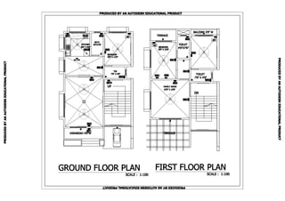
This document contains architectural plans and calculations for a proposed multi-level building project. The plans include ground, raised ground and first, and raised second floor plans. Calculations are provided for the total built up area, deductions, and balcony area for each floor. An area summary table outlines the total proposed area for each floor and ground floor shops/offices. A site plan shows the location of the proposed building on the site and relevant boundaries.
This single sentence document provides a title indicating it contains information about the left side elevation of a building or structure. No other details are given in the document.
The document contains details of the structural framing plan for the first floor of a proposed college building. It includes information on beam sizes, reinforcement details, slab schedules and sections. Key elements discussed are the beam sizes, stirrup spacing, main steel and thickness of different slab types including toilet slabs. Dimensional details of cornice sections are also provided. The document serves as a reference for the structural design and reinforcement layout of the first floor framing.
This document contains a center line plan for a collage building project at Nandgaon Village in Thane district, Maharashtra, India. It lists dimensions for 34 sections of the building labeled C1 through C34. The sections range in size from 350x750 to 850x500. A line drawing shows the layout and dimensions between sections.
This document contains architectural plans and calculations for a proposed multi-level building project. The plans include ground, raised ground and first, and raised second floor plans. Calculations are provided for the total built up area, deductions, and balcony area for each floor. An area summary table outlines the total proposed area for each floor and ground floor shops/offices. A site plan shows the location of the proposed building on the site and relevant boundaries.
This single sentence document provides a title indicating it contains information about the left side elevation of a building or structure. No other details are given in the document.