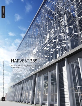
1. HARVEST 365
The most advanced Hydroponic superstructure
in the world.
IntegrationofthemostadvancedhydroponicfarmintheworldTeam1-Integration01
2. CONCEPT 1: RICE PATTY CONCEPT 2: JETSONS
CONCEPT 3: DIRTY DISHES
CONCEPT 4: PODIUM CONCEPT 5: LIGHT WALL
The design team began the concept
by trying to maximize the amount of sunlight re-
ceived by our plants. Our original concept was
inspired by rice patty farming, allowing signifi-
cant amounts of sunlight onto plants by offset-
ting the floors plates. This concept evolved into
the "Jetsons", a scheme to minimize the amount
of shadows that were cast onto a floor plate by
the one above. In concept three, "Dirty Dishes,"
we combined our first two drafts with a larger
first floor that diminished as it grew in elevation.
However, this concept was still inefficient be-
cause it wasn't an improvement over a just a flat
roof with 10,000 ft2
of green space.
Finally a plausible solution was found.
It bore the concept of placing our plants verti-
cally rather than on the horizontal plane. In this
way, the plants would follow the verticality of
the curtain-wall system which then optimized
the desired amount of light for our plants. We
decided to take the envelope and calculate the
area that the sun could reach. It was far over
the benchmark of the top floor plate, reaching
upwards of 15,000 ft2
of potential growing. To
achieve this concept, we had to create systems
that work together to serve a large vertical grow-
ing environment.
For this project our design team combined the ideas of efficiency, technology, modular driven function, and provid-
ing for the community. It was decided that we were going to maximize output of plants as well as create an educational facility
to house some of the largest free standing internal structures in the United States, all for the people of Milwaukee. With our
“All-in-1” modular façade to our split system HVAC, we created efficient ways to heat and cool a habitat ideal for plant growth.
Tackling a multifaceted program including building envelope form studies to a complete set of working drawings. This hydro-
ponic building is one of a kind due to the many integrated variables and "plug-N-play" features that not only help the building
but the community itself.
Team one wants to take you through our process to deliver what could be the most advanced hydroponic farm in the world.
ARRIVAL OF FORM
PARAMETERS AND CODEC
IntegrationofthemostadvancedhydroponicfarmintheworldTeam1-Integration
HARVEST365Team1-2015
02
03
3. Floor 5:
Purpose: Roof Garden/Public
The fifth floor is devoted entirely to hydroponic
systems. Large A-frames on the south side ab-
sorb direct sunlight year round, which is neces-
sary in northern latitudes. The north side is used
for interior commercial growing spaces that
have been artificially lit. This allows us to pro-
duce plants that would otherwise be foreign to
the Wisconsin environment.
Floor 4:
Purpose: Hydroponics/ Commercial
The vertical plants on the south side continue to
absorb natural sunlight, which allows us to grow
more plants within the same volume. The north
side contains interior, or sheltered, plants and
produce preparation stations.
Floor 3:
Purpose: Hydroponics / Education
The hydroponic system takes up 7,000 ft2
of
space on the third floor. Classrooms are located
north of this area in order to obtain a clear view
of the systems to be used as a learning tools.
Floor 2:
Purpose: Gathering / Kitchen
The curtain wall system is prominent and inter-
acts with the second floor. The large atrium is
extended so the occupants can get a grand feel
of the building. All of the commercial/industrial
services are placed on the north side away from
public view
Ground:
Purpose: Retail / Offices
The public and private areas are zoned in an "S"
shaped grid. With private spaces in the back and
public spaces extended off the southwest atri-
um, visitors can easily navigate the building and
appreciate the large scale of the growing spaces.
Facade:
The façade is composed of polycarbonate pan-
els lined in lightweight aluminium, which contain
photovoltaic panels. As a result, the weight of the
façade system is reduced by at least 30%, which
decreases the amount of stress acting on the struc-
ture, while also contributing to the overall scale-
less appearance of the building and a total function
over form.
HVAC:
The building’s commercial/public zoning is set
to follow the “S” shaped grid in order to inte-
grate both the private and public spaces. This
stipulation ensures a right angle design for the
mechanical to be easily integrated into the fa-
cade. By split zoning the commercial spaces and
harvesting zones, we can obtain maximum effi-
ciencies.
Structure:
To further the visual difference between the
public and private zoning, we incorporated
space truss columns. By allowing more natural
light to enter the building we can have a larger
span of area without column placement, where-
as the private spaces are enclosed with more
“traditional” means of construction. The Public
spaces rely on the structure given by the triangu-
lar space trusses that begin at the ground floor,
rise 75ft, and run horizontally to connect up with
the composite steel structure that makes up the
private zone.
FUNCTIONS OF FLOORS
IntegrationofthemostadvancedhydroponicfarmintheworldTeam1-Integration
HARVEST365Team1-2015
04
05
4. Commercial Farming: Horizontal Bed
This space will be strictly climate controlled,
and it will allow for non-indigenous plant growth.
Multiple studies were completed, and three plants -
Basil, Cilantro and Garlic - were found to generate a
substantial profit. After additional tests and trial de-
signs the design team was able to develop a system
of A-frames that would increase total bed sqft from
10,000 to 20,800.
Commercial Educational Farming: A Frame
A large volume (around 81,000 cubic feet) such
as this allows for mass production of local plants
throughout the entire year. This space will be used
to feed the community and integrate agricultural
education with the city. A goal for this system is that
a student may learn, understand and retain the ba-
sic information and unique aspects that make up a
hydroponics farm.
CONSTANT VARIABLE IN ECOSYSTEM
In this new design there are 10 total A-frames, 8 small frames and 2 large. The small frames are 40ft tall, 20ft wide and have
a base width of 10ft, with a total weight of 49,550lbs. Each of these frames will hold a total of 1,344 sqft. per frame. The
large frame is 70ft tall, 20ft in length, and have a base width of 15ft, with a total weight of 89,313 pounds. This frame creates
2,366 sqft. of available bed space.
Building Overall Electrical and Water:
Water Hydroponics Water (gal) Occupant Plumbing (gal) Total
Volume 1752912.418 481590 2,234,502
Price $4,662.75 $1,281.03 $5,943
Electric Lumens Lamp
%
Watts: Fixtures
Required
Cost per
fixure
life span Overall
LED Occupant 3099 100 34.7 100 $206.87 50000 hours $32,302
Artificial Plant
Lighting
2900 59 59 179 $189.68 50000 hours $39,825
Total cost 6
years
$72,127
IntegrationofthemostadvancedhydroponicfarmintheworldTeam1-Integration
HARVEST365Team1-2015
06
07
5. 0
100
200
300
400
500
600
5 10 15 20 25 30 35 40
LightLevels(foot-candles)
Distance from Facade (ft)
Lighting Lab Results
Test 1 Test 2 Test 3 Test 4 Desired
Test 1: Overhang
Avg. Interior Sunlight: 275.1 foot-candles
Test 1 included a roof overhang. This test allowed the team to see how ex-
panding the green roof would directly affect the amount of light that en-
tered the interior spaces.
Afterresearchingmanygreenhousesinthenorth-
ern U.S., the team approximated that 500 foot-can-
dles of light intensity was essential for plant growth.
To test the facade, sensors were placed at the base of
two A-frames in a 1/4" model. Several facade options
were tested as shown below. The conclusion reached
was that no covering or enhancements placed over
the panels would bring the "correct" amount of light
into the green space. The chart to the right explains
the minimum amount of sunlight needed to grow the
specific plants we chose without running the risk of
overloading the mechanical system.
Test 2: Closed Facade
Avg. Interior Sunlight: 343.3 foot-candles
For Test 2, the team removed the building's overhang and placed an
opaque, light-diffusing skin/panel over the top and sides of the building
model.
Test 3: Partial Facade
Avg. Interior Sunlight: 487.9 foot-candles
Test 3 was a modified version of Test 2. With the overhang still being re-
moved, this time only the sides were covered with a light-blocking material.
This way the team could compare the effects of the roof allowing sunlight
into the building with the sides of the building.
ALL IN ONE SYSTEM
Test 4: Fully Exposed
Avg. Interior Sunlight: 525.4 foot-candles
For Test 4 all the coverings on the facade were removed and light was al-
lowed to freely enter the model. This facade iteration yielded the best re-
sults.
Test 1
Test 3
Test 4
Test 2
IntegrationofthemostadvancedhydroponicfarmintheworldTeam1-Integration
HARVEST365Team1-2015
08
09
6. In order to efficiently capture the maximum amount
of desired sunlight available in Milwaukee, our skin system
needed to incorporate photovoltaic panels that converted
light to power as frequently as possible. To accomplish this, a
convex lens was attached to the top of the "light trough" in
order to magnify and direct the sun’s rays toward the center
of the solar panel.
Through solar analysis testing in our Daylighting Lab-
oratory, the design team determined that this method re-
duced the gross square footage of PV panels necessary and
also increased the amount of energy developed upwards of
130%. This then lowered the cost of the overall module pro-
duction.
Polycarbonate System:
Defuses Light as it enters
the green space and works
as an insulator in order to
lower energy costs. It also
prevents glare while still
providing the optimum
visibility.
Louver Vent System:
Allows for the flow of air to
and from the green space
efficiently while blocking a
certain amount of the solar
radiation from entering the
building.
Photovoltaic (PV)
Panels:
Generate free electric-
ity that will be fed back
into our building's system
while also serving as a heat
insulant.
Fan:
Feeds and circulates fresh
clean air into the green
space.
MODULATE TO REGULATE. REPEAT
We wanted to be able to adapt this
system in different environments and
conditions to get the most out of the
intricate facade yet simple facade.
HSS column: 6in. Diameter
Welded connection plate
L-shaped members (angles)
C-channeling
Welded Angle member
Convex Lense
PV panel
Polycarbonate panel
Exploded axon of mullion detail of all Hexagon Modules
Convex testing in daylight lab
Housing for PV panels
IntegrationofthemostadvancedhydroponicfarmintheworldTeam1-Integration
HARVEST365Team1-2015
10
11
7. HVAC
Purpose: Retail
The team decided that the most functional way
to heat and cool the space was to separate it into
3 zones. The first (yellow) being for the user, which
spreads to floors 1 and 2. Using a air handler in the
basement we provided enough CFM to operate
efficiently at these levels. The second zone (green)
would house an air-handler on the fourth floor to
provide enough heating to keep the plants at their
max harvest potential. The VAV system only services
these floors.
For he third system (blue), we tried several ideas and
came to the conclusion that by heating and cooling
the whole atrium, we would be over budget for the
building cost in the range of 35,000 dollars annual-
ly. We decided to retrofit the A frames with heating
fans from the boilers in the basement that only heat
the frames and keep the temperature constant. In
addition to the three systems, a supplemental sys-
tem consisting of three ground source heat pumps
totalling 90 tons.
Heating and Cooling A-frames.
The A-frames were a challenge not only in height and scale but also the problem of how to keep plants
in their required habitat with a constant temperature. By mounting heaters to the A-frames a "natural"
barrier was created in order to allow plants to live and grow in an optimal environment suited to their
needs. In doing this, less energy was needed to heat and cool the space.
Test 1:
For the initial design of the
project the team took the to-
tal tonnage without natu-
ral light and did 100% light-
ed spaces.
Test 2:
On this test the team did a
100% glass facade in all 4 di-
rections with no artificial light
to the space.
Test 3:
This was the option we
went with. By not cooling
and heating the atriums we
found the right tonnage.
SYSTEMS WITHIN SYSTEMS
IntegrationofthemostadvancedhydroponicfarmintheworldTeam1-Integration
HARVEST365Team1-2015
12
13
8. FROM THE TEAM
02
FORM FINDING
01
FROM THE START
04
CONCEPT MODEL
06
INTEGRATE
10
ANALYSIS OF PV
12
DEVELOP
11
BUILD
13
LAYOUT
14
DOUBLE CHECK
09
RENDER FACADE
08
TEST OPTIONS
07
PRELIM SPACES
03
COLLABORATION
05
STUDY SUN FORM
From August to today, there has been a constant wave of trials, failures, and achievements, but most importantly learning. Through the col-
laboration of Architecture and Engineering students, we learned how to break down a massive project into manageable pieces. Through
researching, testing, calculating, and often times repeating, we ended with more than a project; we attained a unique experience that most
students will never achieve before graduation. From concept sketches to construction documents, watching our project evolve from an
idea to reality was an experience that we will apply to our future careers.
15
FINISH
PROCESS DRIVEN
IntegrationofthemostadvancedhydroponicfarmintheworldTeam1-Integration
HARVEST365Team1-2015
14
15