Falcon Invoice Discounting: The best investment platform in india for investors
Flowrox control-valves
1. Flowrox Control Valves for Demanding
Duties
Flowrox control valves are designed for demanding control
applications in which conventional valves encounter problems with
turbulence and wear. Controllability can be further improved with
conical sleeves (reduced ported for the exact Cv required) or smart
positioners. Elastic sleeves have been applied for improved wear
resistance.
Each valve can be sized and optimized for the optimal control range,
to limit wear and velocity and also to prevent cavitation from occurring
in the control valve.
Flowrox control valve sizing is based on international IEC60534
standard (harmonized with ANSI/ISA S75 standards). The valve flow
coefficient Cv defines the control valve flow capacity i.e. the valve
size (diameter).
The optimal control range of the Flowrox valve is between 10-50 %of
opening. Flowrox offers the accurate control and the longest service
life time in the most demanding slurries.
Flowrox provides complementary control valve sizing program to ease
your work (www.flowrox.com).
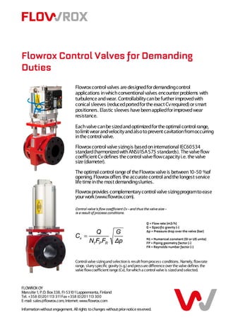
Control valve’s flow coefficient Cv – and thus the valve size –
is a result of process conditions.
Q = Flow rate (m3/h)
G = Specific gravity (-)
∆p = Pressure drop over the valve (bar)
N1 = Numerical constant (SI or US units)
FP = Piping geometry factor (-)
FR = Reynolds number factor (-)
Control valve sizing and selection is result from process conditions. Namely, flow rate
range, slurry specific gravity (s.g.) and pressure difference over the valve defines the
valve flow coefficient range (Cv), for which a control valve is sized and selected.
FLOWROX OY
Marssitie 1, P.O. Box 338, FI-53101 Lappeenranta, Finland
Tel. +358 (0)201 113 311 Fax +358 (0)201 113 300
E-mail: sales@flowrox.com, Internet: www.flowrox.com
Information without engagement. All rights to changes without prior notice reserved.
2. Alternative Structure
Flowrox control valve actuator is equipped with a positioner. The standard signals for various
actuators are as follows:
For Pneumatic Actuators
Electro-pneumatic (AK), input signal 4 -- 20 mA
-
Pneumatic (AN), input signal 0.2 -- 1 bar
-
Can also be accomplished with integrated 4-20 mA module inside the
pneumatic actuator.
For Hydraulic Actuators
Electro-hydraulic (HP), input signal 4-- 20 mA
-
For Electric Actuator
Electronic (EO), input signal 4 -- 20 mA
-
Flowrox Oy was the first pinch valve manufacturer in the world to
get awarded the ISO9001:2000 Quality Certificate in 1997.
Flowrox valves also meet the ANSI/ISA Pinch valve standard
ANSI/ISA 75.10.02.
For Cv tables of open bore and conical sleeves and large diameters,
contact your nearest Flowrox representative (www.flowrox.com). Ask
also for a complementary Flowrox control valve sizing program.
FLOWROX OY
Marssitie 1, P.O. Box 338, FI-53101 Lappeenranta, Finland
Tel. +358 (0)201 113 311 Fax +358 (0)201 113 300
E-mail: sales@flowrox.com, Internet: www.flowrox.com
Information without engagement. All rights to changes without prior notice reserved.