2. Fluid Mechanics 4/4/2012
Dr. B. Rajeevan 2
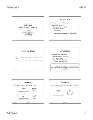
Definitions
Combined Free Surface and Pressurised Flow
4 April 2012 7 Dr. B. Rajeevan
Definitions
Hydraulic Grade Line – HGL
Energy Grade Line ‐ EGL
4 April 2012 8 Dr. B. Rajeevan
Classification of Flows
4 April 2012 9 Dr. B. Rajeevan
Steady & Unsteady Flows
Flow velocity versus time ‐‐‐ ?????
4 April 2012 10 Dr. B. Rajeevan
Uniform & Non‐uniform Flows
Flow velocity at any instant of time does not
vary within the length of channel
Non‐uniform flow = Varied flow
4 April 2012 11 Dr. B. Rajeevan
Varied Flow
Gradually
Varied Flow
Rapidly
Varied Flow
Flow Depth with distance ‐????
4 April 2012 12 Dr. B. Rajeevan
3. Fluid Mechanics 4/4/2012
Dr. B. Rajeevan 3
Laminar & Turbulent Flows
Liquid particles move in definite smooth paths
‐ Viscous force dominates
Liquid particles move in irregular paths
‐ Inertial force dominates
Reynolds's Number
4 April 2012 13 Dr. B. Rajeevan
Laminar & Turbulent Flows
Pipe Flow
L = Pipe Diameter
Open Channel Flow
L = Hydraulic radius or Hydraulic Depth
Hydraulic depth = Flow area/Top surface width
Hydraulic radius = Flow area/Wetted perimeter
Re= 600 – Laminar to Turbulent in Open Channel Flow
Laminar Free Surface Flow is rare
4 April 2012 14 Dr. B. Rajeevan
Subcritical, Supercritical, and Critical
Flows
Fr= 1 – Critical Flow
Fr< 1 – Subcritical Flow
Fr> 1 – Supercritical Flow
4 April 2012 15 Dr. B. Rajeevan
Channels ‐ Terminology
Channels
Natural
Artificial
Canal
Flume
Chute
Tunnel
Culvert
Long channel with Long channel with
mild slope excavated
in ground
Channel above
ground
Channel with steep
bottom slope
Channel excavated
through hills
Short channel running
partially full
4 April 2012 16 Dr. B. Rajeevan
Channels ‐ Terminology
The depth of flow, y, at a section is the vertical distance of the
lowest point of the channel section from the free surface.
The depth of flow section, d, is the depth of flow normal to the
direction of flow.
The stage, Z, is the elevation or vertical distance of free surface
above a specified datum
4 April 2012 17 Dr. B. Rajeevan
Channels ‐ Terminology
Table 1: Properties of Typical Channel Sections
4 April 2012 18 Dr. B. Rajeevan
4. Fluid Mechanics 4/4/2012
Dr. B. Rajeevan 4
Velocity Distribution
4 April 2012 19 Dr. B. Rajeevan
Velocity variation with depth
4 April 2012 20 Dr. B. Rajeevan
Kinetic Energy Correction Factor
V = Instantaneous velocity
Vm = Mean velocity
4 April 2012 21 Dr. B. Rajeevan
Momentum Correction Factor
V = Instantaneous velocity
Vm = Mean velocity
4 April 2012 22 Dr. B. Rajeevan
Example ‐ 1
Considering unit width of channel,
4 April 2012 23 Dr. B. Rajeevan
Example – 1 – cont’d....
4 April 2012 24 Dr. B. Rajeevan
5. Fluid Mechanics 4/4/2012
Dr. B. Rajeevan 5
Example – 1 – cont’d....
END
4 April 2012 25 Dr. B. Rajeevan
Homework
1.
2.
Figure.
4 April 2012 26 Dr. B. Rajeevan
Homework
3.
4.
4 April 2012 27 Dr. B. Rajeevan
Assignment 1
4 April 2012 28 Dr. B. Rajeevan
UNIFORM FLOW
• Flow depth does not change with length
• Normal Depth ‐ ????
• Component of weight of water cause
acceleration
• Shear stress at boundaries cause deceleration
• Imbalance between these forces causes non‐
uniformity in flow
4 April 2012 29 Dr. B. Rajeevan
Uniform and Non‐uniform flows
4 April 2012 30 Dr. B. Rajeevan
6. Fluid Mechanics 4/4/2012
Dr. B. Rajeevan 6
Flow Resistance Equations
• Chezy’s equation
• Manning’s formula
4 April 2012 31 Dr. B. Rajeevan
Chezy’s equation
Assumptions
1) Steady;
2) the slope of the channel bottom is small;
3) Prismatic.
4 April 2012 32 Dr. B. Rajeevan
4 April 2012 Dr. B. Rajeevan 33 4 April 2012 Dr. B. Rajeevan 34
4 April 2012 Dr. B. Rajeevan 35
Resolving all forces in the direction of flow, we get,
Chezy’s equation cont’d...
DEFINITION SKETCH
4 April 2012 36 Dr. B. Rajeevan
7. Fluid Mechanics 4/4/2012
Dr. B. Rajeevan 7
Chezy’s equation cont’d...
CHEZY FORMULA, 1769
4 April 2012 37 Dr. B. Rajeevan
Chezy’s equation cont’d...
Dimension of Chezy’s coefficient, C is L0.5T‐1
Divide by ‘g’ to make C dimensionless
4 April 2012 38 Dr. B. Rajeevan
Darcy‐Weisbach equation
Pipe Flow
Surface
Smooth
Transition
Rough
4 April 2012 39 Dr. B. Rajeevan
Darcy‐Weisbach equation
Pipe Flow
Moody chart – variation of
4 April 2012 40 Dr. B. Rajeevan
Darcy‐Weisbach equation – Open
channels
Open Channel = Conduit cut into two
Moody chart – variation of
4 April 2012 41 Dr. B. Rajeevan
Manning’s Formula
Manning’s Formula
4 April 2012 42 Dr. B. Rajeevan
9. Fluid Mechanics 4/4/2012
Dr. B. Rajeevan 2
Chezy’s equation cont’d...
CHEZY FORMULA, 1769
4 April 2012 7 Dr. B. Rajeevan
Chezy’s equation cont’d...
Dimension of Chezy’s coefficient, C is L0.5T‐1
Divide by to make C dimensionless
4 April 2012 8 Dr. B. Rajeevan
Darcy‐Weisbach equation
Pipe Flow
Surface
Smooth
Transition
Rough
4 April 2012 9 Dr. B. Rajeevan
Darcy‐Weisbach equation
Pipe Flow
Moody chart – variation of
4 April 2012 10 Dr. B. Rajeevan
Darcy‐Weisbach equation – Open
channels
Open Channel = Conduit cut into two
Moody chart – variation of
4 April 2012 11 Dr. B. Rajeevan
Manning’s Equation
Manning’s Formula
4 April 2012 12 Dr. B. Rajeevan
10. Fluid Mechanics 4/4/2012
Dr. B. Rajeevan 3
Most Economical Channel Section
• Max Discharge for a given
– Flow area, A;
– Resistance coefficient, n
– Bottom slope, S
• For a given area, Q is max when V is max
• V is max when R is max(for a given S and n)
• R is max when P is min
4 April 2012 Dr. B. Rajeevan 13
Most Economical Rectangular Channel Section
4 April 2012 Dr. B. Rajeevan 14
y
B
Rectangular channel section is most economical when
depth of flow is equal to half the bottom width of
hydraulic radius is equal to half the depth of flow.
Most Economical Trapezoidal Channel Section
4 April 2012 Dr. B. Rajeevan 15
Half the top width = sloping side length
Most Economical Trapezoidal Channel Section
4 April 2012 Dr. B. Rajeevan 16
Hydraulic Radius, R= Half the flow depth
Most Economical Triangular Channel Section
4 April 2012 Dr. B. Rajeevan 17
Homework 2.1
Most Economical Circular Channel Section
4 April 2012 Dr. B. Rajeevan 18
Condition for Maximum Discharge
11. Fluid Mechanics 4/4/2012
Dr. B. Rajeevan 4
Most Economical Circular Channel Section
4 April 2012 Dr. B. Rajeevan 19
Condition for Maximum Discharge
Most Economical Circular Channel Section
4 April 2012 Dr. B. Rajeevan 20
Condition for Maximum Discharge
Most Economical Circular Channel Section
4 April 2012 Dr. B. Rajeevan 21
Condition for Maximum Mean Velocity of Flow
Homework 2.2
Computation of Uniform Flow
4 April 2012 Dr. B. Rajeevan 22
K = Conveyance of the channel section
When Manning’s formula is used,
Also,
Section Factor
Normal Depth, yn
4 April 2012 Dr. B. Rajeevan
The depth of flow at which uniform flow is maintained in a channel
Worked out Examples
EXAMPLE 1
An irrigation channel of trapezoidal section, having side slopes 3
H: 2 V, is to carry a flow of 10 cumecs on a longitudinal slope of 1
in 5000. The channel is to be lined for which the value of friction
coefficient in Mannings’ formula is n = 0.012. Find the dimensions
of the most economical section of the channel.
4 April 2012 Dr. B. Rajeevan 24
12. Fluid Mechanics 4/4/2012
Dr. B. Rajeevan 5
Example 1 ‐ Solution
4 April 2012 Dr. B. Rajeevan 25
Example 1 ‐ Solution
4 April 2012 Dr. B. Rajeevan 26
For most economical channel
Section,
Also,
Using Manning’s formula,
Worked out Examples
EXAMPLE 2
Water flows at a uniform depth of 2 m in a trapezoidal channel
having a bottom width 6 m, side slopes 2 H: 1 V. If it has to
carry a discharge of 65 m3/s, compute the bottom slope
required to be provided. Take Manning’s n = 0.025.
4 April 2012 Dr. B. Rajeevan 27
Example 2 ‐ Solution
4 April 2012 Dr. B. Rajeevan 28
Specific Energy
4 April 2012 Dr. B. Rajeevan 29
Total Energy per Unit weight
Specific Energy (E) of flow at any section is defined as the energy per unit
weight of water measured with respect to the channel bottom as the datum.
Specific Energy
4 April 2012 Dr. B. Rajeevan 30
13. Fluid Mechanics 4/4/2012
Dr. B. Rajeevan 6
Specific Energy Curve
4 April 2012 Dr. B. Rajeevan 31
Definitions
• Critical Depth,
• Critical Velocity,
• Alternate Depths,
• Subcritical flow or tranquil flow
• Supercritical flow or rapid flow
4 April 2012 Dr. B. Rajeevan 32
Critical Depth
4 April 2012 Dr. B. Rajeevan 33
Condition for Maximum Discharge
4 April 2012 Dr. B. Rajeevan 34
For a given specific energy the discharge in a given channel section is
maximum when the flow is in the critical state.
Specific Force
4 April 2012 Dr. B. Rajeevan 35
Specific Force
4 April 2012 Dr. B. Rajeevan 36
14. Fluid Mechanics 4/4/2012
Dr. B. Rajeevan 7
Minimum Specific Force
4 April 2012 Dr. B. Rajeevan 37
Critical Flow Computations
• For Critical Flow,
4 April 2012 Dr. B. Rajeevan 38
For , Zc is a function of depth of flow. Implies,
for prismatic channels, there is only one depth of flow, yc, which
makes the flow critical. Since, yc is same at all sections of channel,
critical flow in prismatic channels is uniform flow.
Conclusions – Critical Flow
• E is minimum for a given Q
• Q is max for a given E
• F is min for a given Q
• Q is max for a given F
• Velocity head = D/2
• Fr = 1
4 April 2012 Dr. B. Rajeevan 39
Critical Flow in Rectangular Channels
• Bottom Width, B = Top Width, T
• Let q = discharge per unit width
– Q = q × B
• For critical flow,
•
4 April 2012 Dr. B. Rajeevan 40
Critical Flow in Rectangular Channels
4 April 2012 Dr. B. Rajeevan 41
Discharge Diagram
4 April 2012 Dr. B. Rajeevan 42
15. Fluid Mechanics 4/4/2012
Dr. B. Rajeevan 8
• Critical Flows in
– Triangular Channel Section
– Parabolic Channel Section
– Trapezoidal Channel Section
• Application of Specific Energy and Discharge
Diagrams to Channel Transitions
4 April 2012 Dr. B. Rajeevan 43
Exercises
Example 1
An earth canal in good condition is 17 m wide
at bottom and has side slope 2 H: 1V. One
side slope extends to a height of 7.8 m above
the bottom level and the other side extends to
an elevation of 1.8 m, then extends flat to a
distance of 150 m and rises vertically. If the
slope of the canal is 0.7 m per 1610 m,
estimate the discharge when the depth of
water is 2.5 m. Assume Chezy’s C = 35.
4 April 2012 Dr. B. Rajeevan 44
Solution
4 April 2012 Dr. B. Rajeevan 45
2
1
17 m 150 m
2
1
2.5 m
0.7 m
Exercises
• Example 2
For a constant specific energy of 1.8 Nm/N,
calculate the maximum discharge that may
occur in a rectangular channel 5 m wide.
4 April 2012 Dr. B. Rajeevan 46
Example 2 ‐ Solution
4 April 2012 Dr. B. Rajeevan 47
Exercises
• Example 3
A trapezoidal channel has a bottom width
of 6 m and side slopes of 2 H: 1 V. If the
depth of flow is 1.2 m at a discharge of 10
m3/s, compute the specific energy and the
critical depth.
4 April 2012 Dr. B. Rajeevan 48
17. Fluid Mechanics 4/4/2012
Dr. B. Rajeevan 1
2K6CE 404
FLUID MECHANICS ‐ II
Dr. B. Rajeevan
Assistant Professor
Department of Civil Engineering
Government College of Engineering Kannur
Mob: +91 9495 333 088
E‐mail: rajeevan@gcek.ac.in
Contact Hours: 4 pm – 5 pm
Gradually Varied Flow(GVF)
• Examples of GVF
– Flow upstream of river/dam
– Flow downstream of a sluice gate
– Flow in channels with break in slopes
4 April 2012 Dr. B. Rajeevan 2
A steady non‐uniform flow in a prismatic channel with
gradual changes in its water surface elevation
GVF‐Examples
4 April 2012 Dr. B. Rajeevan 3 4 April 2012 Dr. B. Rajeevan 4
GVF‐Examples
Assumptions
• The pressure distribution at any section is
hydrostatic
– A gradual change in surface curvature give rise to
negligible normal accelerations.
• The resistance to flow at any depth is given by
corresponding uniform flow equation with
slope replaced with energy slope.
4 April 2012 Dr. B. Rajeevan 5
Assumptions‐cont’d...
4 April 2012 Dr. B. Rajeevan 6
• The bottom slope of the channel is very small
• Prismatic
• = 1
• n is independent of depth of flow
The slope of the channel bottom may be assumed small if it is less than 5 percent. In
such a case, sin tan , in which = angle of the channel bottom with
horizontal, and the flow depths measured vertically or normal to the bottom are
approximately the same.
18. Fluid Mechanics 4/4/2012
Dr. B. Rajeevan 2
Differential Equation
4 April 2012 Dr. B. Rajeevan 7
DATUM
4 April 2012 Dr. B. Rajeevan 8
Wide Rectangular Channel
4 April 2012 Dr. B. Rajeevan 9
Using Chezy’s
Equation
4 April 2012 Dr. B. Rajeevan 10
For rising water surface
4 April 2012 Dr. B. Rajeevan 11
For falling water surface
HOMEWORK
Classification of Bottom Slopes
4 April 2012 Dr. B. Rajeevan 12
For a given channel with a known
Q = Discharge,
n = Manning coefficient, and
S0 =Channel bed slope,
yc = critical water depth and yn = Uniform flow depth can be
computed.
There are three possible relations between yn and yc as
1) yn > yc ,
2) yn < yc ,
3) yn = yc .
19. Fluid Mechanics 4/4/2012
Dr. B. Rajeevan 3
Classification of Bottom Slopes
4 April 2012 Dr. B. Rajeevan 13
For horizontal and adverse slope channels, uniform flow depth
yn does not exist.
Classification of Bottom Slopes
4 April 2012 Dr. B. Rajeevan 14
Classification of Bottom Slopes
• Critical
• Mild
• Steep
• Horizontal
• Adverse
4 April 2012 Dr. B. Rajeevan 15
Zones
4 April 2012 Dr. B. Rajeevan 16
Zones
4 April 2012 Dr. B. Rajeevan 17
Zones
4 April 2012 Dr. B. Rajeevan 18
20. Fluid Mechanics 4/4/2012
Dr. B. Rajeevan 4
Zones
4 April 2012 Dr. B. Rajeevan 19
Water Surface Profiles
4 April 2012 Dr. B. Rajeevan 20
– M‐curve
– S‐curve
– C‐curve
– H‐curve
– A‐curve
Water Surface Profiles
4 April 2012 Dr. B. Rajeevan 21
Water Surface Profiles
4 April 2012 Dr. B. Rajeevan 22
12
Backwater and Drawdown Curves
• Depth of flow increases in the direction of flow
(dy/dx is +ve) – curve (Zone 1 & 3)
• Depth of flow decreases in the direction of flow
(dy/dx is ‐ve) – curve (Zone 2)
4 April 2012 Dr. B. Rajeevan 23
Equation of GVF
4 April 2012 Dr. B. Rajeevan 24
21. Fluid Mechanics 4/4/2012
Dr. B. Rajeevan 5
Characteristics of Surface Profiles
4 April 2012 Dr. B. Rajeevan 25
Characteristics of Surface Profiles
4 April 2012 Dr. B. Rajeevan 26
Self study
• Surface Profiles in Critical sloped channels
• Surface Profiles in Horizontal sloped channels
• Surface Profiles in Adverse sloped channels
4 April 2012 Dr. B. Rajeevan 27
Example 1
• Flow depth in a section of the non‐uniform
flow reach of the channel is 2.9 m. Determine
the type of flow profile in the channel. Take yc
= 2.63 m and yn = 3.17 m.
4 April 2012 Dr. B. Rajeevan 28
Example 1 ‐ Solution
• Given, y = 2.9 m ; yc = 2.63 m and yn = 3.17 m.
• Since yn > yc, slope is mild.
• Also, yc < y < yn, profile is in Zone 2.
• Hence it is M2 curve.
4 April 2012 Dr. B. Rajeevan 29
Example 2
• A rectangular channel with a bottom width of
4 m and a bottom slope of 0.0008 has a
discharge of 1.5 m3/s. In a gradually‐varied
flow in this channel, the depth at a certain
location is found to be 0.3 m. Assuming n =
0.016, determine the type of GVF profile.
4 April 2012 Dr. B. Rajeevan 30
22. Fluid Mechanics 4/4/2012
Dr. B. Rajeevan 6
Solution
4 April 2012 Dr. B. Rajeevan 31
Step 1: Determine normal depth, yn
Step2: Determine critical depth, yc
Step 3: Compare given y with normal depth and identify the slope.
Step 4: Compare normal depth and critical depth with given depth
and determine the type of curve.
Solution
4 April 2012 Dr. B. Rajeevan 32
Solving by trial and error,
Critical Depth,
Type of Profile
Practical Examples
4 April 2012 Dr. B. Rajeevan 33
Practical Examples
4 April 2012 Dr. B. Rajeevan 34
Practical Examples
4 April 2012 Dr. B. Rajeevan 35
Practical Examples
4 April 2012 Dr. B. Rajeevan 36
23. Fluid Mechanics 4/4/2012
Dr. B. Rajeevan 7
4 April 2012 Dr. B. Rajeevan 37
Why ?
• All major hydraulic engineering activities
• Determination of the effect of a hydraulic
structure on the channel
• Inundation of land
• Estimation of the flood zone
4 April 2012 Dr. B. Rajeevan 38
Methods
• Step Method
• Graphical Integration Method
• Direct Integration Method
4 April 2012 Dr. B. Rajeevan 39
Step Method
4 April 2012 Dr. B. Rajeevan 40
Step Method
4 April 2012 Dr. B. Rajeevan 41
Steps
4 April 2012 Dr. B. Rajeevan 42
24. Fluid Mechanics 4/4/2012
Dr. B. Rajeevan 8
Graphical Integration Method
4 April 2012 Dr. B. Rajeevan 43
Direct Integration Method – Bresse’s
Method
• Wide rectangular channels
• Chezy’s equation is used
4 April 2012 Dr. B. Rajeevan 44
4 April 2012 Dr. B. Rajeevan 45 4 April 2012 Dr. B. Rajeevan 46
Example 1
A rectangular channel 7.5 m wide has a uniform depth of flow
of 2 m and has a bed slope of 1 in 3000. If due to weir
constructed at the downstream end of the channel, water
surface at a section is raised by 0.75 m, determine the water
surface slope with respect to horizontal at this section.
Assume Manning’s n =0.02.
4 April 2012 Dr. B. Rajeevan 47
7.5 m
2 m
Solution
4 April 2012 Dr. B. Rajeevan 48
25. Fluid Mechanics 4/4/2012
Dr. B. Rajeevan 9
Example 2
A rectangular channel 10 m wide carries a discharge of 30
cumecs. It is laid at a slope of 0.0001. If at a section in this
channel the depth is 1.6 m, how far (upstream or
downstream) from the section will the depth be 2.0 m? Take
Manning’s n = 0.015.
4 April 2012 Dr. B. Rajeevan 49
Solution
4 April 2012 Dr. B. Rajeevan 50
4 April 2012 Dr. B. Rajeevan 51
Self study
• Direct Integration Method
Backhmeteff method
Chow method
4 April 2012 Dr. B. Rajeevan 52
4 April 2012 Dr. B. Rajeevan 53
END OF MODULE –II (GVF)
4 April 2012 Dr. B. Rajeevan 54
26. Fluid Mechanics 4/4/2012
Dr. B. Rajeevan 1
2K6CE 404
FLUID MECHANICS ‐ II
Dr. B. Rajeevan
Assistant Professor
Department of Civil Engineering
Government College of Engineering Kannur
Mob: +91 9495 333 088
E‐mail: rajeevan@gcek.ac.in
Contact Hours: 4 pm – 5 pm
• Stream lines in Uniform flow and GVF are
parallel – acceleration negligible – pressure
distribution hydrostatic
4 April 2012 Dr. B. Rajeevan 2
SHALLOW WATER THEORY
In Rapidly varied flow, the sectional area of flow
changes abruptly within a short distance. Turbulent
eddying loss is more important than boundary friction
in this case. Hydraulic jump is a typical example of
rapidly varied flow.
4 April 2012 Dr. B. Rajeevan 3
Rapidly Varied Flow (RVF)
• Streamlines have sharp curvatures –
nonparallel‐Non hydrostatic pressure
distribution
• Flow profile discontinuous due to rapid
change of flow depth
• Analyzed using Boussinesq and Fawer
assumptions
4 April 2012 Dr. B. Rajeevan 4
Assumptions
• In the Boussinesq assumption, the vertical
flow velocity is assumed to vary linearly from
zero at the channel bottom to the maximum
at the free surface.
• In the Fawer assumption, this variation is
assumed to be exponential.
4 April 2012 Dr. B. Rajeevan 5
Assumptions
• Before and after jump formation flow is uniform
and pressure distribution is hydrostatic
• The length of jump is small – loss due to friction
neglected
• Component of weight of water along flow
direction is neglected
4 April 2012 Dr. B. Rajeevan 6
27. Fluid Mechanics 4/4/2012
Dr. B. Rajeevan 2
Characteristics of RVF
• Streamlines are not parallel
• Variation in the cross‐sectional shape and size, due to change
in the flow direction
4 April 2012 Dr. B. Rajeevan 7
Fig. 4.1 Definition sketch for abrupt drop
4 April 2012 Dr. B. Rajeevan 8
General Equation of Hydraulic Jump
4 April 2012 Dr. B. Rajeevan 9
General Equation of Hydraulic Jump
4 April 2012 Dr. B. Rajeevan 10
4 April 2012 Dr. B. Rajeevan 11
Conjugate Depths
Hydraulic jump in rectangular channels
4 April 2012 Dr. B. Rajeevan 12
Relation between conjugate
depths
28. Fluid Mechanics 4/4/2012
Dr. B. Rajeevan 3
Hydraulic jump in rectangular channels
4 April 2012 Dr. B. Rajeevan 13
Hydraulic jump in rectangular channels
4 April 2012 Dr. B. Rajeevan 14
4 April 2012 Dr. B. Rajeevan 15
Example 1
• A horizontal rectangular channel 4 m wide
carries a discharge of 16 cumecs. Determine
whether a hydraulic jump may occur at an
initial depth of 0.5 m. If a jump occurs,
determine the sequent depth to this initial
depth. Also, determine the energy loss in the
jump.
4 April 2012 Dr. B. Rajeevan 16
Solution
4 April 2012 Dr. B. Rajeevan 17
Example 2
• In a rectangular channel there occurs a jump
corresponding to = 2.5. Determine the
critical depth and head loss in terms of the
initial depth,
4 April 2012 Dr. B. Rajeevan 18
29. Fluid Mechanics 4/4/2012
Dr. B. Rajeevan 4
Solution
4 April 2012 Dr. B. Rajeevan 19
Types of Hydraulic Jump
• Undular jump
• Weak jump
• Oscillating jump
• Steady jump
• Strong jump
4 April 2012 Dr. B. Rajeevan 20
4 April 2012 Dr. B. Rajeevan 21 4 April 2012 Dr. B. Rajeevan 22
Applications of Hydraulic Jump
• Dissipation of excess energy
• Raised water level
• Increases the weight on apron
• Increases the discharge through sluices
• Mixing of chemicals
4 April 2012 Dr. B. Rajeevan 23
SURGES
• Moving wave which makes abrupt changes in
depth of flow.
• Moving Hydraulic Jump
• Sudden opening and closing of gates
• Positive or negative
– Increase or decrease in depth of flow
4 April 2012 Dr. B. Rajeevan 24
A surge is a moving wave front which results in an abrupt change
of the depth of flow. It is a rapidly varied unsteady flow condition.
30. Fluid Mechanics 4/4/2012
Dr. B. Rajeevan 5
4 April 2012 Dr. B. Rajeevan 25
Positive Surge
4 April 2012 Dr. B. Rajeevan 26
Definition Sketch for Surge Movement
4 April 2012 Dr. B. Rajeevan 27
Consider the movement of a positive surge wave in x‐direction in an open channel
having an irregular cross section as shown in Figure above. Here, as the surge
moves with an absolute velocity, Vw, flow depth becomes equal to y2 behind the
surge. Undistributed flow depth ahead of the surge is y1. The corresponding flow
velocities behind and ahead of the slope front are V2 and V1 respectively. The
surge has been created due to a sudden change of flow rate from Q1 to Q2. In this
context, the problem definition for surge computation is: given Q1,y1,Q2 and
channel slope parameters, determine the surge wave velocity, Vw and the surge
height, y2‐y1. Equations for computing the above are based on the basic principles
of conservation of mass and momentum.
Assumptions
Following assumptions are made in the derivation.
Channel is horizontal and frictionless;
Pressure distribution is hydrostatic at locations away
from the front;
Velocity is uniform within the cross section, at
location away from the front;
Change in the flow depth at the front occurs over a
very short distance;
wave shape, height, and wave velocity do not change
as the wave propagates in the channel;
water surfaces behind and ahead of the wave front
are parallel to the bed
4 April 2012 Dr. B. Rajeevan 28
Derivation of Equations
We first choose a control volume encompassing the
wave front. This control volume can be made
stationary by superimposing a constant velocity, Vw
(equal to the absolute velocity of surge wave) in the
negative x‐direction.
Thus the unsteady flow of previous Figure may be
transformed to steady flow in the Figure that
follows, and the principles of conservation of mass
and momentum can be applied to a steady flow
situation.
4 April 2012 Dr. B. Rajeevan 29
Surge movement viewed as steady flow
4 April 2012 Dr. B. Rajeevan 30
Applying continuity equation to the control volume of above Figure, we get
31. Fluid Mechanics 4/4/2012
Dr. B. Rajeevan 6
4 April 2012 Dr. B. Rajeevan 31
in which, ρ = density of water; A2 = flow area behind the wave and A1 = flow area
ahead of the wave.
‐‐‐‐‐‐‐‐‐‐‐‐‐‐ (1)
‐‐‐‐‐‐‐‐‐‐‐‐‐‐ (2)
Equation (2) can also be written as
‐‐‐‐‐‐‐‐‐‐‐‐‐‐ (3)
Another way of writing the continuity equation is
‐‐‐‐‐‐‐‐‐‐‐‐‐‐ (4)
Since ρ is a constant, Eq. (1) may be written as
4 April 2012 Dr. B. Rajeevan 32
Applying momentum equation to the control volume
‐‐‐‐‐‐‐‐‐‐‐‐‐‐ (5)
The channel is prismatic, horizontal and frictionless. Therefore, the only force acting on
the control volume is pressure force.
Pressure force acts in the positive x ‐ direction at the inlet section and in the negative x ‐
direction at the outlet section. Equation (5) can be written as
‐‐‐‐‐‐‐‐‐‐‐‐‐‐ (6)
= depth to the centroid of inlet section of the C.V.
=depth of the centroid of outlet section.
4 April 2012 Dr. B. Rajeevan 33
Substitution of Eq. (2) in Eq (6) leads to
‐‐‐‐‐‐‐‐‐‐‐‐‐‐ (7)
Substitution of Eq. (3) in Eq. (7) and subsequent simplification leads to
‐‐‐‐‐‐‐‐‐‐‐‐‐‐ (8)
Here, wave is propagating in the downstream direction.
Therefore, Vw should be greater than V1.
4 April 2012 Dr. B. Rajeevan 34
‐‐‐‐‐‐‐‐‐‐‐‐‐‐ (9)
‐‐‐‐‐‐‐‐‐‐‐‐‐(10)
Now, substitution of Eq. (4) in Eq. (7) and subsequent simplification leads to
‐‐‐‐‐‐‐‐‐‐‐‐ (11)
4 April 2012 Dr. B. Rajeevan 35
Equations (10) and (11) can be used to determine the surge wave velocity and
the surge height, if we know the values of undisturbed flow depth, y1, flow rate
before the surge, Q1, and the flow rate after the surge, Q2.
Equations (10) and (11) are non‐linear equations. They can be solved by an
appropriate numerical technique.
For rectangular channels, Eqs. (10) and (11) simplify to the following.
‐‐‐‐‐‐‐‐‐‐‐‐ (12)
‐‐‐‐‐‐‐‐‐‐‐‐ (13)
4 April 2012 Dr. B. Rajeevan 36
32. Fluid Mechanics 4/4/2012
Dr. B. Rajeevan 7
4 April 2012 Dr. B. Rajeevan 37
Self Study
• Positive Surge – Case b
• Negative Surge
• Location of Hydraulic Jump
4 April 2012 Dr. B. Rajeevan 38
Energy Dissipators
• Stilling basins
• Flip Buckets
• Roller Buckets
4 April 2012 Dr. B. Rajeevan 39
Stilling Basin
4 April 2012 Dr. B. Rajeevan 40
The hydraulic jump is used for energy dissipation in a stilling basin
Head less than 50 m
Chute blocks
Baffle blocks
End sills
Stilling Basin
4 April 2012 Dr. B. Rajeevan 41
• The chute blocks serrate the flow entering the
basin and lift up part of the jet. This produces
more eddies increasing energy dissipation, the
jump length is decreased, and the tendency of
the jump to sweep out of the basin is reduced.
• The baffle blocks stabilize the jump and
dissipate energy due to impact.
• The sill stabilizes the jump and inhibits the
tendency of the jump to sweep out.
Standardized Stilling Basins
• St. Anthony Falls stilling basin;
• Stilling basins developed by the U.S. Bureau of
Reclamation (each suitable for a certain range
of head)
• A basin recommended by the U.S. Army Corps
of Engineers
4 April 2012 Dr. B. Rajeevan 42
33. Fluid Mechanics 4/4/2012
Dr. B. Rajeevan 8
Stilling Basin
4 April 2012 Dr. B. Rajeevan 43
U.S. Army Corps of Engineers stilling basin
Stilling Basin
4 April 2012 Dr. B. Rajeevan 44
Stilling Basin
4 April 2012 Dr. B. Rajeevan 45
Flip Buckets
• The flip bucket energy disspator is suitable for sites where the tail
water depth is low (which would require a large amount of
excavation if a hydraulic jump dissipator were used) and the rock in
the downstream area is good and resistant to erosion.
• The flip bucket, also called ski‐jump dissipator, throws the jet at a
sufficient distance away from the spillway where a large scour hole
may be produced. Initially, the jet impact causes the channel
bottom to scour and erode. The scour hole is then enlarged by a
ball‐mill motion of the eroded rock pieces in the scour hole. A
plunge pool may be excavated prior to the first spill for controlled
erosion and to keep the plunge pool in a desired location.
• A small amount of the energy of the jet is dissipated by the internal
turbulence and the shearing action of the surrounding air as it
travels in the air. However, most of the energy of the jet is
dissipated in the plunge pool.
4 April 2012 Dr. B. Rajeevan 46
Flip Bucket
4 April 2012 Dr. B. Rajeevan 47
Flip Bucket
4 April 2012 Dr. B. Rajeevan 48
34. Fluid Mechanics 4/4/2012
Dr. B. Rajeevan 9
Roller Bucket
• A roller bucket may be used for energy
dissipation if the downstream depth is
significantly greater than that required for the
formation of a hydraulic jump.
• In this dissipator, the dissipation is caused mainly
by two rollers: counterclockwise roller near the
water surface above the bucket and a roller on
the channel bottom downstream of the bucket.
• The movement of these rollers along with the
intermixing of the incoming flows results in the
dissipation of energy.
4 April 2012 Dr. B. Rajeevan 49
Roller Bucket
4 April 2012 Dr. B. Rajeevan 50
4 April 2012 Dr. B. Rajeevan 51
Plunge Pool
A plunge pool is an energy dissipating device located at the outlet of a spillway.
Energy is dissipated as the discharge flows into the plunge pool. Plunge pools are
commonly lined with rock riprap or other material to prevent excessive erosion of
the pool area. Discharge from the plunge pool should be at the natural streambed
elevation. Typical problems may include movement of the riprap, loss of fines from
the bedding material and scour beyond the riprap and lining.
36. Fluid Mechanics 4/4/2012
Dr. B. Rajeevan 2
4 April 2012 Dr. B. Rajeevan 7
General Layout with Reaction Turbine
4 April 2012 Dr. B. Rajeevan 8
General Layout with Impulse Turbine
4 April 2012 Dr. B. Rajeevan 9
Advantages of Hydroelectric Power
• Hydroelectricity is a renewable energy resource.
• Hydroelectricity is one of the most efficient energy sources because most
of the kinetic energy of the water is converted to electrical energy.
• No greenhouse gases or other dangerous gases are produced so there is
no damage of this kind to the environment.
• No fuel is needed, therefore the price of hydroelectricity will not change if
the price of fuel increases.
• Hydroelectric plants are generally less expensive to run than other
generating plants.
• Electricity can be generated almost straight away compared to coal‐fired
power stations which take several hours to start.
• Electricity can be stored for later use by using excess production to pump
water to a higher altitude facility until it is released again to generate
electricity.
• Hydroelectric plants only need a turbine and generator where as coal‐fired
stations need a furnace, boiler, condenser, cooling towers etc.
4 April 2012 Dr. B. Rajeevan 10
Disadvantages of Hydroelectric Power
• The construction of hydroelectric plants is
expensive.
• Hydroelectric plants are site specific. In other
words you can't build them just anywhere.
• Hydroelectric plants can have a detrimental effect
on the river flow and water supply. The
construction of hydroelectric plants usually
means that areas of land will be flooded. This
means that habitats for animals and plants are
lost. People living in the area may also lose their
land.
4 April 2012 Dr. B. Rajeevan 11
Head
• Head
– Gross Head (H1) – Difference between head and
tail races
– Net Head (H) – Head at entrance to turbine
• = H1 Losses(hf)
4 April 2012 Dr. B. Rajeevan 12
37. Fluid Mechanics 4/4/2012
Dr. B. Rajeevan 3
Losses of Energy
4 April 2012 Dr. B. Rajeevan 13
Efficiency
• Hydraulic efficiency
• Mechanical efficiency
• Volumetric efficiency
• Overall efficiency
4 April 2012 Dr. B. Rajeevan 14
Hydraulic Efficiency
4 April 2012 Dr. B. Rajeevan 15
Mechanical Efficiency
4 April 2012 Dr. B. Rajeevan 16
Volumetric Efficiency
4 April 2012 Dr. B. Rajeevan 17
Overall Efficiency
4 April 2012 Dr. B. Rajeevan 18
38. Fluid Mechanics 4/4/2012
Dr. B. Rajeevan 4
4 April 2012 Dr. B. Rajeevan 19
TURBINES
Impulse
Pelton
Wheel
Reaction
Francis
Kaplan
Classification of Turbines
4 April 2012 Dr. B. Rajeevan 20
TURBINES
Tangential
flow
Radial flow Axial flow Mixed flow
Classification of Turbines
Pelton wheel Kaplan turbine
4 April 2012 Dr. B. Rajeevan 21
TURBINES
High head (>
250 m)
Medium head
(60 – 250 m)
Low head (<
60 m)
Classification of Turbines
Pelton wheel Francis Turbine Kaplan Turbine
4 April 2012 Dr. B. Rajeevan 22
TURBINES
Specific speed
(8.5 ‐ 30)
Medium head
(50 ‐ 340)
Low head
(255 ‐ 860)
Classification of Turbines
Pelton wheel Francis Turbine Kaplan Turbine
4 April 2012 Dr. B. Rajeevan 23
Runner
Vane/Bucket/Blade
Impulse Turbine
• A nozzle at the end of penstock transforms
water under a high head into a powerful jet.
The momentum of this jet is destroyed by
striking the runner, which absorbs the
resulting force. If the velocity of the water
leaving the runner is nearly zero, all of the
kinetic energy of the jet will be transformed
into mechanical energy, so the efficiency is
high.
4 April 2012 Dr. B. Rajeevan 24
39. Fluid Mechanics 4/4/2012
Dr. B. Rajeevan 5
4 April 2012 Dr. B. Rajeevan 25 4 April 2012 Dr. B. Rajeevan 26
4 April 2012 Dr. B. Rajeevan 27 4 April 2012 Dr. B. Rajeevan 28
Plan view of a Pelton turbine
installation (courtesy Voith
Siemens Hydro Power Generation).
4 April 2012 Dr. B. Rajeevan 29
Pelton Wheel
4 April 2012 Dr. B. Rajeevan 30
41. Fluid Mechanics 4/4/2012
Dr. B. Rajeevan 7
Reaction Turbine
• Only a part of the energy of water available at
the turbine entrance is converted to KE and a
substantial part remains as pressure energy.
• Change from pressure to KE energy takes
gradually while the runner moves. For this
change to take place, the runner must be
encased to contain the water pressure (or
suction), or they must be fully submerged in
the water flow.
4 April 2012 Dr. B. Rajeevan 37
Reaction Turbine cont’d …
• Reaction turbines are acted on by water,
which changes pressure as it moves through
the turbine and gives up its energy.
• Newton's third law describes the transfer of
energy for reaction turbines.
• Most water turbines in use are reaction
turbines and are used in low (< 30m) and
medium (30 300m)head applications.
4 April 2012 Dr. B. Rajeevan 38
4 April 2012 Dr. B. Rajeevan 39
Francis Turbine
• Francis turbines are radial flow reaction turbines, with
fixed runner blades and adjustable guide vanes, used
for medium heads.
• In the high speed Francis the admission is always radial
but the outlet is axial.
•
Francis turbines can be set in an open flume or
attached to a penstock.
•
4 April 2012 Dr. B. Rajeevan 40
Francis Turbine cont’d …
• For small heads and power open flumes are commonly
employed.
• Steel spiral casings are used for higher heads,
designing the casing so that the tangential velocity of
the water is constant along the consecutive sections
around the circumference.
• Small runners are usually made in aluminum bronze
castings. Large runners are fabricated from curved
stainless steel plates, welded to a cast steel hub.
4 April 2012 Dr. B. Rajeevan 41 4 April 2012 Dr. B. Rajeevan 42
42. Fluid Mechanics 4/4/2012
Dr. B. Rajeevan 8
4 April 2012 Dr. B. Rajeevan 43
A Francis turbine runner, rated at nearly one
million hp (750 MW), being installed at the
Grand Coulee Dam, United States.
Parts of Francis Turbine
4 April 2012 Dr. B. Rajeevan 44
Part Name Purpose
Scroll Casing/Spiral
Casing
Provide an even distribution of water around runner‐leads to
constant velocity of water‐ c/s area gradually decreased.
Made of cast steel/plate steel/concrete/concrete and steel
Speed Ring/Stay
Ring
Upper and lower rings held together by stay vanes
Directs water from the scroll case to guide vanes
Resists the load imposed upon it by internal water pressure and
weight of turbine & generator to foundation
Made of cast iron/cast steel/fabricated steel
Stay vanes No of stay vanes = half the no of guide vanes
Guide vanes Fixed on the periphery of runner
Regulates the quantity of water supplied to the runner
Airfoil shaped
Made of cast steel/stainless steel/plate steel
Parts of Francis Turbine
4 April 2012 Dr. B. Rajeevan 45
Part Name Purpose
Runner Series of curved vanes(16 to 24 in number) evenly arranged
Water enters the runner radially and leaves axially – creates a
force to rotate the runner
Made of cast iron/ cast steel/mild steel/stainless steel
Shaft Made of forged steel
Used to transfer the torque created by runner to generator
Draft Tube Water from runner to tail race via draft tube
Made of cast steel/Plate steel/Concrete
Airtight
Lower end submerged below the tail water level
Permits negative/suction head to be developed so that the
turbine can be placed above the tail water level
Converts kinetic energy to pressure energy
Draft Tube
4 April 2012 Dr. B. Rajeevan 46
Draft Tube
• In reaction turbines, to reduce the kinetic energy still
remaining in the water leaving the runner a draft tube or
diffuser stands between the turbine and the tail race.
• A well‐designed draft tube allows, within certain limits, the
turbine to be installed above the tailwater elevation
without losing any head.
• As the kinetic energy is proportional to the square of the
velocity one of the draft tube objectives is to reduce the
outlet velocity.
•
4 April 2012 Dr. B. Rajeevan 47
Draft Tube
• An efficient draft tube would have a conical section but the
angle cannot be too large, otherwise flow separation will
occur. The optimum angle is 7° but to reduce the draft tube
length, and therefore its cost, sometimes angles are
increased up to 15°.
• Draft tubes are particularly important in high‐speed
turbines, where water leaves the runner at very high
speeds. In horizontal axis machines the spiral casing must
be well anchored in the foundation to prevent vibration
that would reduce the range of discharges accepted by the
turbine.
4 April 2012 Dr. B. Rajeevan 48
45. Fluid Mechanics 4/4/2012
Dr. B. Rajeevan 1
2K6CE 404
FLUID MECHANICS ‐ II
Dr. B. Rajeevan
Assistant Professor
Department of Civil Engineering
Government College of Engineering Kannur
Mob: +91 9495 333 088
E‐mail: rajeevan@gcek.ac.in
Contact Hours: 4 pm – 5 pm
Pumps
• A pump is a machine which converts mechanical energy to
fluid energy, the fluid being incompressible. This action is
opposite to that in hydraulic turbines.
• A pump is a device used to move fluids, such as gases,
liquids or slurries.
• A pump displaces a volume by physical or mechanical
action.
• One common misconception about pumps is that they
create pressure. Pumps alone do not create pressure; they
only displace fluid, causing a flow. Adding resistance to flow
causes pressure.
• Pumps fall into two major groups: positive displacement
pumps and rotodynamic pumps. Their names describe the
method for moving a fluid.
4 April 2012 Dr. B. Rajeevan 2
Classification of Pumps
4 April 2012 Dr. B. Rajeevan 3
Positive displacement pumps
• The principle of action, in all positive
displacement pumps, is purely static. These
pumps are also called as ‘static pumps’.
• The pumps, operated under this principle, are
reciprocating, screw, ram,plunger, gear, lobe,
perialistic, diaphram, radial piston, axial piston
etc.
4 April 2012 Dr. B. Rajeevan 4
Rotodynamic pumps
• In rotodynamic pumps, however, the energy is
transferred by rotary motion and by dynamic
action.
• The rotating blade system imparts a force on
the fluid, which is in contact with the blade
system at all points, thereby making the fluid
to move i.e., transferring mechanical energy of
the blade system to kinetic energy of the fluid.
4 April 2012 Dr. B. Rajeevan 5
RECIPROCATING PUMPS
PUMPS
4 April 2012 Dr. B. Rajeevan 6
46. Fluid Mechanics 4/4/2012
Dr. B. Rajeevan 2
Working Principle of Reciprocating Pump
4 April 2012 Dr. B. Rajeevan 7
Components of reciprocating pumps
• Components of reciprocating pumps:‐
a) Piston or plunger: – a piston or plunger that reciprocates in a closely
fitted cylinder.
b) Crank and Connecting rod: – crank and connecting rod mechanism
operated by a power source. Power source gives rotary motion to
crank. With the help of connecting rod we translate reciprocating
motion to piston in the cylinder.
c) Suction pipe: – one end of suction pipe remains dip in the liquid and
other end attached to the inlet of the cylinder.
d) Delivery pipe: – one end of delivery pipe attached with delivery part
and other end at discharge point.
e) Suction and Delivery valves: – suction and delivery valves are
provided at the suction end and delivery end respectively. These valves
are non‐return valves.
4 April 2012 Dr. B. Rajeevan 8
WORKING OF RECIPROCATING PUMP
• Operation of reciprocating motion is done by the
power source (i.e. electric motor or i.c engine, etc).
• Power source gives rotary motion to crank;
• with the help of connecting rod we translate
reciprocating motion to piston in the cylinder (i.e.
intermediate link between connecting rod and piston).
• When crank moves from inner dead centre to outer
dead centre vacuum will create in the cylinder.
• When piston moves outer dead centre to inner dead
centre and piston force the water at outlet or delivery
value.
4 April 2012 Dr. B. Rajeevan 9
EXPRESSION FOR DISCHARGE OF THE
RECIPROCATING PUMP
4 April 2012 Dr. B. Rajeevan 10
Where: –
Q: – discharge in m3/sec
A: – cross‐section of piston or cylinder in m2
L: – length of stroke in meter
N: – speed of crank in r.p.m
CENTRIFUGAL PUMPS
PUMPS
4 April 2012 Dr. B. Rajeevan 11
Introduction
• Centrifugal pumps are the most widely used
of all the turbo machine (or rotodynamic)
pumps.
• This type of pumps uses the centrifugal force
created by an impeller which spins at high
speed inside the pump casing.
4 April 2012 Dr. B. Rajeevan 12
47. Fluid Mechanics 4/4/2012
Dr. B. Rajeevan 3
Components
• Stationery
• Rotary
4 April 2012 Dr. B. Rajeevan 13
Stationery Components
a) Casing: – It is an air tight passage surrounding the impeller. It is designed in such a
way that the kinetic energy of the water discharged at the outlet of the impeller is
converted into pressure energy before the water leaves the casing and enters the
delivery pipe. Types of casing:‐
Volute casing: – It is spiral type of casing in which area of flow increase gradually. The increase in
area of flow decreases the velocity of flow and increases the pressure of water.
Vortex casing: – if a circular chamber is introduced between casing and the impeller, the casing is
known as vortex casing.
Casing with guide blades: – the impeller is surrounded by a series of guide blades mounted on a
ring know as diffuser.
b) Suction pipe: – a pipe whose one ends is connected to the inlet of the pump and
other end dip into water in a sump.
c) Delivery pipe: – a pipe whose one end is connected to the outlet of the pump and
other end is involved in delivering the water at a required height.
4 April 2012 Dr. B. Rajeevan 14
Rotary Components
Impeller: – It is the main rotating part that provides the centrifugal
acceleration to the fluid.
Classification of impeller:
a) Based on direction of flow:
∙ Axial‐flow: – the fluid maintains significant axial‐flow direction components from the inlet to
outlet of the rotor.
∙ Radial‐flow: – the flow across the blades involves a substantial radial‐flow component at the
rotor inlet, outlet and both.
∙ Mixed‐flow: – there may be significant axial and radial flow velocity components for the flow
through the rotor row.
b) Based on suction type:
∙ Single suction: – liquid inlet on one side.
∙ Double suction: – liquid inlet to the impeller symmetrically from both sides.
c) Based on mechanical construction:
∙ Closed: – shrouds or sidewall is enclosing the vanes.
∙ Open: – no shrouds or wall to enclose the vanes.
∙ Semi‐open or vortex type.
4 April 2012 Dr. B. Rajeevan 15
Working Principle of Centrifugal Pump
4 April 2012 Dr. B. Rajeevan 16
WORKING
• Water is drawn into the pump from the source of
supply through a short length of pipe (suction pipe).
Impeller rotates; it spins the liquid sitting in the cavities
between the vanes outwards and provides centrifugal
acceleration with the kinetic energy.
• This kinetic energy of a liquid coming out an impeller is
harnessed by creating a resistance to flow. The first
resistance is created by the pump volute (casing) that
catches the liquid and shows it down.
• In the discharge nozzle, the liquid further decelerates
and its velocity is converted to pressure according to
BERNOULLI’S PRINCIPAL.
4 April 2012 Dr. B. Rajeevan 17
SPECIFIC SPEED
• speed of an imaginary pump geometrically
similar in every respect to the actual pump
and capable of delivering unit quantity against
a unit head.
• It is denoted by NS
4 April 2012 Dr. B. Rajeevan 18
Where: –
N: – pump speed in r.p.m
Q: – discharge in m3/sec
H: – head per stage in meter
48. Fluid Mechanics 4/4/2012
Dr. B. Rajeevan 4
Specific Speed
4 April 2012 Dr. B. Rajeevan 19
EFFICIENCIES OF CENTRIFUGAL PUMPS
• Mechanical efficiencies: – It is ratio of the
impeller power to the shaft power.
• Hydraulic efficiencies: – It is ratio of the
manometric head to the Euler head.
• Volumetric efficiencies:‐ It is ratio of the
actual to the theoretical discharge.
• Overall efficiencies: – It is ratio of the water
power to the shaft power.
4 April 2012 Dr. B. Rajeevan 20
CAVITATION
4 April 2012 Dr. B. Rajeevan 21
Definition
• Cavitation is the formation and then immediate implosion (inward
bursting) of cavities in a liquid – i.e. small liquid‐free zones ("bubbles") –
that are the consequence of forces acting upon the liquid.
• It usually occurs when a liquid is subjected to rapid changes of pressure
that cause the formation of cavities where the pressure is relatively low.
• Cavitation is transient unsteady phenomenon characterized by a growth of
holes or cavities.
• Cavitation creates problem in operation of all three types of centrifugal
pumps viz. radial, mixed and axial flow pumps, whenever high discharge,
high rotational speed or low head is encountered.
• Pumps with low specific speed are more susceptible to cavitation as
compared to high specific speed pumps.
4 April 2012 Dr. B. Rajeevan 22
4 April 2012 Dr. B. Rajeevan 23 4 April 2012 Dr. B. Rajeevan 24
As the vapor bubbles move along the impeller vanes, the pressure around the
bubbles begins to increase until a point is reached where the pressure on the outside
of the bubble is greater than the pressure inside the bubble.
The bubble collapses. The process is not an explosion but rather an implosion (inward
bursting). Hundreds of bubbles collapse at approximately the same point on each
impeller vane.
Bubbles collapse non‐symmetrically such that the surrounding liquid rushes to fill the
void forming a liquid microjet. The micro jet subsequently ruptures the bubble with
such force that a hammering action occurs. Bubble collapse pressures greater than 1
GPa have been reported.
The highly localized hammering effect can pit the pump impeller. After the bubble
collapses, a shock wave emanates outward from the point of collapse. This shock
wave is what we actually hear and what we call "cavitation".
49. Fluid Mechanics 4/4/2012
Dr. B. Rajeevan 5
4 April 2012 Dr. B. Rajeevan 25
Cavitation is a significant cause of wear in some engineering
contexts. When entering high pressure areas, cavitation bubbles
that implode on a metal surface cause cyclic stress. This results in
surface fatigue of the metal causing a type of wear also called
"cavitation".
The most common examples of this kind of wear are pump
impellers and bends when a sudden change in the direction of
liquid occurs.
Cavitation is usually divided into two classes of behaviour: inertial
(or transient) cavitation and non‐inertial cavitation.
4 April 2012 Dr. B. Rajeevan 26
Inertial cavitation is the process where a void or bubble in a liquid
rapidly collapses, producing a shock wave. Inertial cavitation occurs
in nature in the strikes of mantis shrimps and pistol shrimps, as
well as in the vascular tissues of plants. In man‐made objects, it
can occur in control valves, pumps, propellers and impellers.
Non inertial cavitation is the process in which a bubble in a fluid is
forced to oscillate in size or shape due to some form of energy
input, such as an acoustic field. Such cavitation is often employed
in ultrasonic cleaning baths and can also be observed in pumps,
propellers, etc.
4 April 2012 Dr. B. Rajeevan 27
Since the shock waves formed by cavitation are strong enough to
significantly damage moving parts, cavitation is usually an undesirable
phenomenon.
It is specifically avoided in the design of machines such as turbines or
propellers, and eliminating cavitation is a major field in the study of fluid
dynamics.
Cavitation damage on a valve plate for
an axial piston hydraulic pump
4 April 2012 Dr. B. Rajeevan 28
4 April 2012 Dr. B. Rajeevan 29
Cavitation damage to a Francis turbine.
Types of Cavitation
• Traveling Cavitation: As name suggests, this
type of cavitation is not a steady one, it moves
from place to place within pump.
• Fixed Cavitation: This type of cavitation is fixed
at a place and hardly changes its position.
• Vortex Cavitation: Here vortex i.e. circular flow
is generated and thereby occurrence of
cavitation.
• Vibratory Cavitation.
4 April 2012 Dr. B. Rajeevan 30
50. Fluid Mechanics 4/4/2012
Dr. B. Rajeevan 6
Effects of Cavitation
Harmful Effects of Cavitation
• Cavitation affects the performance of various hydraulic
machines like pumps, turbines etc. This reduces their
overall efficiency.
• Noise is generated which is unwanted everywhere but
in some cases like submarines noise must not be
generated as it may create the problem while hiding.
• Drag force increases in cavitation parts.
• Due to braking of bubbles shock waves are produced
which generates vibrations. Vibrations are damn
dangerous at very high speeds.
• Material damage due to erosion.
4 April 2012 Dr. B. Rajeevan 31
Beneficial Effects of Cavitation
• Cavitation can be used for agitation and
mixing.
• A cavitation noise boomer can be used as
sound source for an echo ranging survey of
ocean bottom conditions.
• Jet cavitation can be used very effectively for
tunneling through rock.
4 April 2012 Dr. B. Rajeevan 32
Methods to Avoid Cavitation Damage
• Primary Design.
• Air Injection.
• Cathodic Protection.
• Hydrogen Evolution.
• Corrosion Inhibitors.
4 April 2012 Dr. B. Rajeevan 33
CAVITATION
IN PUMPS
4 April 2012 Dr. B. Rajeevan 34
Cavitation in Pumps
4 April 2012 Dr. B. Rajeevan 35 4 April 2012 Dr. B. Rajeevan 36
51. Fluid Mechanics 4/4/2012
Dr. B. Rajeevan 7
4 April 2012 Dr. B. Rajeevan 37
CAVITATION
IN TURBINES
4 April 2012 Dr. B. Rajeevan 38
4 April 2012 Dr. B. Rajeevan 39 4 April 2012 Dr. B. Rajeevan 40
4 April 2012 Dr. B. Rajeevan 41 4 April 2012 Dr. B. Rajeevan 42