Service oven listrik 081381278719
•
0 likes•564 views

Service Kompor Gas dan Oven listrik Ariston seperti kita ketahui bahwa kompor gas merupakan alat yang paling sering digunakan dirumah Anda, oleh karena itu kompor gas harus selalu dalam kondisi prima agar aman digunakan menerima jasa perbaikan untuk semua permasalahan kompor gas dirumah Anda. Beberapa kerusakan kompor gas yang dapat kami tangani adalah Ariston, Modena, Delizia, Azalea, Ram Armalia, Electrolux, Diamante, Covina, Tecnogas, La Germania Induksi, Portable DLL.
![2
Important Notes to the Installer
1. Read all instructions contained in these installation
instructions before installing range.
2. Removeallpackingmaterialfromtheovencompartments
before connecting the gas and electrical supply to the
range.
3. Observeallgoverningcodesandordinances.
4. Be sure to leave these instructions with the consumer.
Important Note to the Consumer
1. Keep these instructions with your Use & Care Guide for
future reference.
IMPORTANT SAFETY INSTRUCTIONS
Installation of this range must conform with local codes or, in
the absence of local codes, with the National Fuel Gas Code
ANSI Z223.1—latest edition when installed in the United
States.
Wheninstalledinamanufactured(mobile)home,installation
mustconformwiththeManufacturedHomeConstructionand
SafetyStandard,Title24CFR,Part3280[formerlytheFederal
Standard for Mobile Home Construction and Safety, Title 24,
HUD(Part280)]or,whensuchstandardisnotapplicable,the
StandardforManufacturedHomeInstallations,ANSI/NCSBCS
A225.1, or with local codes.
ThisrangehasbeendesigncertifiedbyCSAInternational.As
with any appliance using gas and generating heat, there are
certainsafetyprecautionsyoushouldfollow.Youwillfindthem
in the Use & Care Guide, read it carefully.
• Besureyourrangeisinstalledandgroundedproperly
by a qualified installer or service technician.
• This range must be electrically grounded in
accordance with local codes or, in their absence,
withtheNationalElectricalCodeANSI/NFPANo .70—
latest edition when installed in the United States.
See Grounding Instructions on page 5.
• Before installing the range in an area covered with
linoleum or any other synthetic floor covering, make
sure the floor covering can withstand heat at least
90°F above room temperature without shrinking,
warping or discoloring. Do not install the range over
carpeting unless you place an insulating pad or sheet of
1/4-inchthickplywoodbetweentherangeandcarpeting.
• Make sure the wall coverings around the range can
withstand the heat generated by the range.
• Donotobstructtheflowofcombustionairattheoven
vent nor around the base or beneath the lower front
panel of the range. Avoid touching the vent openings or
nearby surfaces as they may become hot while the oven
is in operation. This range requires fresh air for proper
burner combustion.
Never leave children alone or unattended
in the area where an appliance is in use. As children grow,
teachthemtheproper,safeuseofallappliances.Neverleave
the oven door open when the range is unattended.
Stepping, leaning or sitting on the doors
ordrawersofthisrangecanresultinseriousinjuriesand
can also cause damage to the range.
• Do not store items of interest to children in the
cabinets above the range. Children could be seriously
burned climbing on the range to reach items.
• To eliminate the need to reach over the surface
burners, cabinet storage space above the burners
should be avoided.
• Adjust surface burner flame size so it does not
extend beyond the edge of the cooking utensil.
Excessive flame is hazardous.
• Do not use the oven as a storage space. This creates
a potentially hazardous situation.
• Never use your range for warming or heating the
room. Prolonged use of the range without adequate
ventilationcanbedangerous.
• Do not store or use gasoline or other flammable
vapors and liquids near this or any other appliance.
Explosions or fires could result.
• Reset all controls to the "off" position after using a
programmable timing operation.
FORMODELSWITHSELF-CLEANFEATURE:
• Remove broiler pan, food and other utensils before
self-cleaningtheoven.Wipeupexcessspillage.Follow
the cleaning instructions in the Use & Care Guide.
• Unlike the standard gas range, THIS COOKTOP IS
NOTREMOVABLE.Donotattempttoremovethecooktop.
DO NOT MAKE ANY ATTEMPT TO
OPERATETHEELECTRICIGNITIONOVENDURINGAN
ELECTRICAL POWER FAILURE. RESET ALL OVEN
CONTROLS TO "OFF" IN THE EVENT OF A POWER
FAILURE.
Theelectricignitorwillautomaticallyre-ignitetheovenburner
when power resumes if the oven thermostat control was left
in the "ON" position.
When an electrical power failure occurs during use, the
surface burners will continue to operate.
During a power outage, the surface burners can be lit with a
match. Hold a lighted match to the burner, then slowly turn
the knob to the LITE position. Use extreme caution when
lighting burners this way.
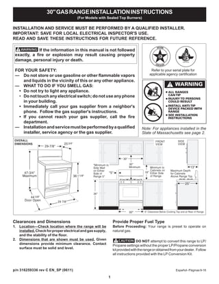
30"GASRANGEINSTALLATIONINSTRUCTIONS
(For Models with Sealed Top Burners)
Special instructions for appliances installed in the State of
Massachusetts: This appliance can only be installed in the
State of Massachusetts by a Massachusetts licensed
plumber or gas fitter. When using a flexible gas connector, it
must not exceed 3 feet (36 inches) in length. A "T" handle
type manual gas valve must be installed in the gas supply
line to this appliance.
• Air curtain or other overhead range hoods, which operate
by blowing a downward air flow on to a range, shall not be
used in conjunction with gas ranges other than when the
hood and range have been designed, tested and listed by
anindependenttestlaboratoryforuseincombinationwith
each other.](data:image/gif;base64,R0lGODlhAQABAIAAAAAAAP///yH5BAEAAAAALAAAAAABAAEAAAIBRAA7)
Recommended
More Related Content
Similar to Service oven listrik 081381278719
Similar to Service oven listrik 081381278719 (20)
Recently uploaded
Recently uploaded (20)
Service oven listrik 081381278719
- 1. 1 INSTALLATION AND SERVICE MUST BE PERFORMED BY A QUALIFIED INSTALLER. IMPORTANT: SAVE FOR LOCAL ELECTRICAL INSPECTOR'S USE. READ AND SAVE THESE INSTRUCTIONS FOR FUTURE REFERENCE. Clearances and Dimensions 1. Location—Check location where the range will be installed.Checkforproperelectricalandgassupply, and the stability of the floor. 2. Dimensions that are shown must be used. Given dimensions provide minimum clearance. Contact surface must be solid and level. Provide Proper Fuel Type Before Proceeding: Your range is preset to operate on natural gas. DO NOT attempt to convert this range to LP/ Propane settings without the proper LP/Propane conversion kitprovidedwiththerangeorobtainedfromyourdealer. Follow all instructions provided with the LP Conversion Kit. Español-Páginas9-16 30"GASRANGEINSTALLATIONINSTRUCTIONS (For Models with Sealed Top Burners) If the information in this manual is not followed exactly, a fire or explosion may result causing property damage, personal injury or death. FOR YOUR SAFETY: — Do not store or use gasoline or other flammable vapors and liquids in the vicinity of this or any other appliance. — WHAT TO DO IF YOU SMELL GAS: • Do not try to light any appliance. • Do not touch any electrical switch; do not use any phone in your building. • Immediately call your gas supplier from a neighbor's phone. Follow the gas supplier's instructions. • If you cannot reach your gas supplier, call the fire department. — Installationandservicemustbeperformedbyaqualified installer, service agency or the gas supplier. 44 5/8" Note: For appliances installed in the State of Massachusetts see page 2. Refer to your serial plate for applicable agency certification 30" p/n 316259336 rev C EN_SP (0611)
- 2. 2 Important Notes to the Installer 1. Read all instructions contained in these installation instructions before installing range. 2. Removeallpackingmaterialfromtheovencompartments before connecting the gas and electrical supply to the range. 3. Observeallgoverningcodesandordinances. 4. Be sure to leave these instructions with the consumer. Important Note to the Consumer 1. Keep these instructions with your Use & Care Guide for future reference. IMPORTANT SAFETY INSTRUCTIONS Installation of this range must conform with local codes or, in the absence of local codes, with the National Fuel Gas Code ANSI Z223.1—latest edition when installed in the United States. Wheninstalledinamanufactured(mobile)home,installation mustconformwiththeManufacturedHomeConstructionand SafetyStandard,Title24CFR,Part3280[formerlytheFederal Standard for Mobile Home Construction and Safety, Title 24, HUD(Part280)]or,whensuchstandardisnotapplicable,the StandardforManufacturedHomeInstallations,ANSI/NCSBCS A225.1, or with local codes. ThisrangehasbeendesigncertifiedbyCSAInternational.As with any appliance using gas and generating heat, there are certainsafetyprecautionsyoushouldfollow.Youwillfindthem in the Use & Care Guide, read it carefully. • Besureyourrangeisinstalledandgroundedproperly by a qualified installer or service technician. • This range must be electrically grounded in accordance with local codes or, in their absence, withtheNationalElectricalCodeANSI/NFPANo .70— latest edition when installed in the United States. See Grounding Instructions on page 5. • Before installing the range in an area covered with linoleum or any other synthetic floor covering, make sure the floor covering can withstand heat at least 90°F above room temperature without shrinking, warping or discoloring. Do not install the range over carpeting unless you place an insulating pad or sheet of 1/4-inchthickplywoodbetweentherangeandcarpeting. • Make sure the wall coverings around the range can withstand the heat generated by the range. • Donotobstructtheflowofcombustionairattheoven vent nor around the base or beneath the lower front panel of the range. Avoid touching the vent openings or nearby surfaces as they may become hot while the oven is in operation. This range requires fresh air for proper burner combustion. Never leave children alone or unattended in the area where an appliance is in use. As children grow, teachthemtheproper,safeuseofallappliances.Neverleave the oven door open when the range is unattended. Stepping, leaning or sitting on the doors ordrawersofthisrangecanresultinseriousinjuriesand can also cause damage to the range. • Do not store items of interest to children in the cabinets above the range. Children could be seriously burned climbing on the range to reach items. • To eliminate the need to reach over the surface burners, cabinet storage space above the burners should be avoided. • Adjust surface burner flame size so it does not extend beyond the edge of the cooking utensil. Excessive flame is hazardous. • Do not use the oven as a storage space. This creates a potentially hazardous situation. • Never use your range for warming or heating the room. Prolonged use of the range without adequate ventilationcanbedangerous. • Do not store or use gasoline or other flammable vapors and liquids near this or any other appliance. Explosions or fires could result. • Reset all controls to the "off" position after using a programmable timing operation. FORMODELSWITHSELF-CLEANFEATURE: • Remove broiler pan, food and other utensils before self-cleaningtheoven.Wipeupexcessspillage.Follow the cleaning instructions in the Use & Care Guide. • Unlike the standard gas range, THIS COOKTOP IS NOTREMOVABLE.Donotattempttoremovethecooktop. DO NOT MAKE ANY ATTEMPT TO OPERATETHEELECTRICIGNITIONOVENDURINGAN ELECTRICAL POWER FAILURE. RESET ALL OVEN CONTROLS TO "OFF" IN THE EVENT OF A POWER FAILURE. Theelectricignitorwillautomaticallyre-ignitetheovenburner when power resumes if the oven thermostat control was left in the "ON" position. When an electrical power failure occurs during use, the surface burners will continue to operate. During a power outage, the surface burners can be lit with a match. Hold a lighted match to the burner, then slowly turn the knob to the LITE position. Use extreme caution when lighting burners this way. 30"GASRANGEINSTALLATIONINSTRUCTIONS (For Models with Sealed Top Burners) Special instructions for appliances installed in the State of Massachusetts: This appliance can only be installed in the State of Massachusetts by a Massachusetts licensed plumber or gas fitter. When using a flexible gas connector, it must not exceed 3 feet (36 inches) in length. A "T" handle type manual gas valve must be installed in the gas supply line to this appliance. • Air curtain or other overhead range hoods, which operate by blowing a downward air flow on to a range, shall not be used in conjunction with gas ranges other than when the hood and range have been designed, tested and listed by anindependenttestlaboratoryforuseincombinationwith each other.
- 3. 3 Before Starting Tools You Will Need For leveling legs and Anti-Tip Bracket: • Adjustable wrench or channel lock pliers • 5/16" Nutdriver or Flat Head Screw Driver • Electric Drill & 1/8" Diameter Drill Bit (5/32" Masonry Drill Bit if installing in concrete) For gas supply connection: • Pipe wrench For burner flame adjustment: • Phillips head and blade-type screwdrivers For gas conversion (LP/Propane or Natural): • Open end wrench - 1/2" Additional Materials You Will Need • Gas line shut-off valve • Pipe joint sealant that resists action of LP/Propane gas • A new flexible metal appliance conduit (1/2" NPT x 3/4" or1/2"I.D.)mustbedesigncertifiedbyCSAInternational. Because solid pipe restricts moving the range we recommend using a new flexible conduit (4 to 5 foot length) for each new installation and additional reinstallations. • Always use the (2) new flare union adapters (1/2" NPT x 3/4" or 1/2" I.D.) supplied with the new flexible appliance conduit for connection of the range. NormalInstallationSteps 1. Anti-Tip Bracket Installation Instructions Important Safety Warning To reduce the risk of tipping of the range, the range must be secured to the floor by properly installed anti-tip bracket and screws packed with the range. Failure to install the anti-tip bracket will allow the range to tip over if excessive weight is placed on an open door or if a child climbs upon it. Serious injury might result from spilled hot liquids or from the range itself. If range is ever moved to a different location, the anti-tip brackets must also be moved and installed with the range. Instructions are provided for installation in wood or cement fastened to either the floor or wall. When installed to the wall, make sure that screws completely penetrate dry wall and are secured in wood or metal. When fastening to the floor or wall, be sure that screws do not penetrate electrical wiring or plumbing. A. LocatetheBracketUsingtheTemplate -(Bracketmay belocatedoneithertheleftorrightsideoftherange. Use the information below to locate the bracket if template is notavailable). Markthefloororwallwhereleftorrightside of the range will be located. If rear of range is against the wallornofurtherthan1-1/4"fromwallwheninstalled,you may use the wall or floor mount method. If molding is installedanddoesnotallowthebrackettofitflushagainst thewall,removemoldingormountbrackettothefloor.For wall mount, locate the bracket by placing the back edge of the template against the rear wall and the side edge of template on the mark made referencing the side of the range.Placebracketontopoftemplateandmarklocation of the screw holes in wall. If rear of range is further than 1-1/4" from the wall when installed, attach bracket to the floor. For floor mount, locate the bracket by placing back edge of the template where the rear of the range will be located. Mark the location of the screw holes, shown in template. B. Drill Pilot Holes and Fasten Bracket - Drill a 1/8" pilot hole where screws are to be located. If bracket is to be mounted to the wall, drill pilot hole at an approximate 20° downward angle. If bracket is to be mounted to masonry or ceramic floors, drill a 5/32" pilot hole 1-3/4" deep. The screwsprovidedmaybeusedinwoodorconcretematerial. Usea5/16"nut-driverorflatheadscrewdrivertosecurethe bracket in place. 30"GASRANGEINSTALLATIONINSTRUCTIONS (For Models with Sealed Top Burners)
- 4. 4 C. LevelandPositionRange-Levelrangebyadjustingthe (4)levelinglegswithawrench.Note:Aminimumclearance of1/8"isrequiredbetweenthebottomoftherangeandthe levelinglegtoallowroomforthebracket. Useaspiritlevel tocheckyouradjustments. Sliderangebackintoposition. Visually check that rear leveling leg is inserted into and fully secured by the Anti-Tip Bracket by removing lower panelorstoragedrawer.Formodelswithawarmerdrawer or broiler compartment, grasp the top rear edge of the range and carefully attempt to tilt it forward. 2. Provide an adequate gas supply. This unit is pre-set to operate on 4" natural gas manifold pressure.Aconvertiblepressureregulatorisconnectedtothe manifoldandMUSTbeconnectedinserieswiththegassupply line. If the LP/Propane conversion kit has been used, follow instructions provided with the kit for converting the pressure regulator to LP/Propane use. The LP kit can be found on the back side of the range (some models). Caremustbetakenduringinstallationofrangenottoobstruct the flow of combustion and ventilation air. For proper operation, the maximum inlet pressure to the regulator should be no more than 14 inches of water column pressure. The inlet pressure to the regulator must be at least 1 inch greater than regulator manifold pressure. Examples: If regulator is set for natural gas 4 inch manifold pressure, inlet pressure must be at least 5 inches; if regulator has been convertedforLP/Propanegas10inchmanifoldpressure,inlet pressure must be at least 11 inches. Leaktestingoftheapplianceshallbeconductedaccordingto the instructions in step 4g. The gas supply line should be 1/2" or 3/4" I.D. 3. Seal wall openings. Sealanyopeningsinthewallbehindtherangeandinthefloor under the range after gas supply line is installed. 30"GASRANGEINSTALLATIONINSTRUCTIONS (For Models with Sealed Top Burners) 4. Connect the range to the gas supply. NOTE: To prevent leaks use pipe joint sealant on all male (outside)pipethreads. Fig. 4a Fig. 4b Fig. 4c
- 5. 5 30"GASRANGEINSTALLATIONINSTRUCTIONS (For Models with Sealed Top Burners) 5. Read these electrical connection details first then connect electricity to range. Before servicing, disconnect electrical supply at circuit breaker, fuse or power cord. Electric Requirements: A dedicated, properly grounded and polarizedbranchcircuitprotectedbya15amp.circuitbreaker or time delay fuse. See serial plate for proper voltage. Extension Cord Precautions: Becauseofpotentialsafetyhazardsundercertainconditions, we strongly recommend against the use of any extension cord. However, if you still elect to use an extension cord, it is absolutely necessary that it be a UL listed 3-wire grounding type appliance extension cord and that the current carrying rating of the cord in amperes be equivalent to or greater than thebranchcircuitrating.Suchextensioncordsareobtainable through your local service organization. Do not use flame to check for gas leaks. Checking Manifold Gas Pressure Disconnecttherangeanditsindividualshut-offvalvefromthe gas supply piping system during any pressure testing of that system at test pressures greater than 14" of water column pressure (approximately 1/2" psig). The appliance must be isolated from the gas supply piping system by closing its individual manual shut-off valve during any pressure testing of the gas supply piping system at test pressures equal to or less than 14" of water column pressure (approximately 1/2" psig). If it should be necessary to check the manifold gas pressure, connectmanometer(watergauge)orotherpressuredeviceto thetopburnerrightrearorifice. Usingarubberhosewithinside diameter of approximately 1/4," hold tubing down tight over orifice. Turnburnervalveon. Foranaccuratepressurecheckhaveatleasttwo(2)othertop burners burning. Be sure the gas supply (inlet) pressure is at least one inch above specified range manifold pressure. The gas supply pressure should never be over 14" water column. WhenproperlyadjustedforNaturalGasthemanifoldpressure is 4." (For LP/Propane Gas the manifold pressure is 10.") DO NOT allow regulator to turn on pipe when tightening fittings. a) Installanexternalmanualgasshut-offvalvetogassupply lineinanaccessiblelocationoutsideoftherange.Besure you know where and how to shut off the gas supply to the range. b) Install1/2"flareunionadaptertopressureregulatorusing NO MORE THAN 15ft./lbs. of torque NOTE: Be sure to stabilize the left side of the pressure regulator with adjustable wrench before tightening ANY fittings to the pressure regulator (Refer to Fig. 4d). c) Tighten the gas supply fitting and/or appliance conduit to flareunionontherightsideofthepressureregulator using NOMORETHAN15ft./lbs.oftorque.Besuretostabilize “ ON ” Fig. 4d Fig. 4e Fig. 4f the 1/2" flare union adapter with an adjustable wrench before tightening the gas supply fitting and/or appliance conduit (Refer to Fig. 4e). d) Installflareunionadaptertoexternalmanualshut-offvalve. e) Attach appliance conduit to flare union on shut-off valve. f) Makesureserviceshut-offvalveonpressureregulator is in the "ON" position (See Fig. 4f). g) Check for leaks. Turn the gas supply on to the range and use a liquid leak detector at all joints and conduits to check for leaks in the system.
- 6. 6 30" GAS RANGE INSTALLATION INSTRUCTIONS (For Models with Sealed Top Burners) 6.AssemblyoftheSurfaceBurnerHeads,Burner Caps and Burner Grates: ItisveryimportanttomakessurethatalloftheSurfaceBurner Heads, Surface Burner Caps and Surface Burner Grates are installed correctly and in the correct locations (See Fig. 1). 1. Match the letter located under center of Burner Cap with letters located inside the Burner Heads (See Fig. 1). 2. Match the letter stamped on the Burner Skirt with the Burner Head and Burner Cap. Each of the Burner Heads MUSThaveaBurnerCapinstalledtoinsureproperignition andgasflamesize.Note:TheBurnerElectrodesmustbe located properly in slot of each Burner Head (See Fig. 2). Fig. 1 Burner sizes and locations Front of cooktop Fig. 2 Burner Assembly Where a standard two-prong wall receptacle is encountered, it is the personal responsibility and obligation of the customer to have it replaced with a properly grounded three-prong wall receptacle. DONOT,UNDERANYCIRCUMSTANCES,CUTORREMOVE THETHIRD(GROUND)PRONGFROMTHEPOWERCORD. PLEASE READ CAREFULLY! For personal safety, this product must be properly grounded. GroundingInstructions The power cord of this appliance is equipped with a 3-prong (grounding) plug which mates with a standard 3-prong grounding wall receptacle to minimize the possibility of electric shock hazard from this appliance. The customer should have the wall receptacle and circuit checked by a qualified electrician to make sure the receptacle is properly groundedandpolarized.
- 7. 7 30" GAS RANGE INSTALLATION INSTRUCTIONS (For Models with Sealed Top Burners) Operation of Oven Burners and Oven Adjustments 9. Electric Ignition Burners Operation of electric igniters should be checked after range and supply line connectors have been carefully checked for leaks and range has been connected to electric power. Theovenburnerisequippedwithanelectriccontrolsystemas wellasanelectricovenburnerigniter.Ifyourmodelisequipped withawaist-highbroilburner,itwillalsohaveanelectricburner igniter. These control systems require no adjustment. When the oven is set to operate, current will flow to the igniter. It will "glow" similar to a light bulb. When the igniter has reached a temperaturesufficienttoignitegas,theelectricallycontrolled ovenvalvewillopenandflamewillappearattheovenburner. There is a time lapse from 30 to 60 seconds after the thermostatisturnedONbeforetheflameappearsattheoven burner. When the oven reaches the dial setting, the glowing igniter will go off. The burner flame will go "out" in 20 to 30 seconds after the igniter goes "OFF." To maintain any given oven temperature, this cycle will continue as long as the dial (or display) is set to operate. After removing all packing materials and literature from the oven: a) Set oven to BAKE at 300ºF. See Use & Care Guide for operatinginstructions. b) Within 60 seconds the oven burner should ignite. Check forproperflame,andallowtheburnertocycleonce.Reset controls to off. c) Ifyourmodelisequippedwithawaist-highbroiler,setoven toBROIL.SeeUse&CareGuideforoperatinginstructions. d) Within 60 seconds the broil burner should ignite. Check for proper flame. Reset controls to off. Adjust flame until you can quickly turn knob from LITE to LOWEST POSITION without extinguishing the flame. Flame should be as small as possible without going out. Note: Air mixture adjustment is not required on surface burners. Test to verify if “LOW” setting should be adjusted a. Push in and turn control to LITE until burner ignites. b. Push in and quickly turn knob to LOWEST POSITION. c. If burner goes out, reset control to OFF. d. Removethesurfaceburnercontrolknob. e. Insertathin-bladedscrewdriverintothehollowvalvestem and engage the slotted screw inside. Flame size can be increased or decreased with the turn of the screw. Turn counterclockwisetoincreaseflamesize. Turnclockwise to decrease flame size. To Surface Burner 8. Adjust the "LOW" Setting of Surface Burner Valve (Linear Flow Valves Only): Fig. 1 7. Electric Ignition Surface Burners Operation of electric igniters should be checked after range and supply line connectors have been carefully checked for leaks and range has been connected to electric power. a. To check for proper lighting, push in and turn a surface burner knob counterclockwise to the LITE position. You will hear the igniter sparking (See Fig. 1). b. The surface burner should light when gas is available to the top burner. Purge air from supply lines by leaving knob in the LITE position until burner ignites. Each burner should light within four (4) seconds in normal operation after air has been purged from supply lines. c. Visually check that burner has lit. Once the burner lights, the control knob should be turned out of the LITE position. d. There are separate electrodes (igniters) for each burner. Try each knob separately until all burner valves have been checked. REMEMBER — DO NOT ALLOW SPILLS, FOOD, CLEANING AGENTS OR ANY OTHER MATERIAL TO ENTER THE GAS ORIFICE HOLDER OPENING. Always keep the Burner Caps and Burner Heads in place whenever the surface burners are in use.
- 8. 8 Before You Call for Service Readthe"BeforeYouCall"andoperatinginstructionsections in your Use & Care Guide. It may save you time and expense. The list includes common occurrences that are not the result of defective workmanship or materials in this appliance. Refertothewarrantyinyour Use&CareGuideforourtoll-free service number and address. Please call or write if you have inquiriesaboutyourrangeproductand/orneedtoorderparts. 30" GAS RANGE INSTALLATION INSTRUCTIONS (For Models with Sealed Top Burners) Care, Cleaning and Maintenance Refer to the Use & Care Guide for cleaning instructions. Ifremovingtherangeisnecessaryforcleaningormaintenance, shut off gas supply. Disconnect the gas and electrical supply. If the gas or electrical supply is inaccessible, lift the unit slightly at the front and pull out away from the wall. Pull only as far as necessary to disconnect the gas and electrical supply. Finish removing the unit for servicing and cleaning. Reinstall in reverse order making sure to level the range and check gas connections for leaks. See page 3, step 1 for proper anchoring instructions. Model and Serial Number Location For sealed burner ovens, the identification plate is located on theright-handsurfaceoftheovenfrontframeatthestorageor warmer drawer; or the lower panel area. Whenorderingpartsforormakinginquiresaboutyourrange, always be sure to include the model and serial numbers and alotnumberorletterfromtheidentificationplateonyourrange. Youridentificationplatealsotellsyoutheratingoftheburners, the type of fuel and the pressure the range was adjusted for when it left the factory.11.Air Shutter-Broil Burner The approximate flame length of the broil burner is 1 inch (distinct inner, blue flame). To determine if the broil burner flame is proper, set the oven to broil. Iftheflameisyellowincolor,increaseairshutteropeningsize. (See "2" in illustration above.) If the flame is a distinct blue, reduce the air shutter opening size. To adjust, loosen lock screw (see "3" in illustration above), reposition air shutter, and tighten lock screw. 10. Air Shutter-Oven Burner The approximate flame length of the oven burner is 1 inch (distinct inner, blue flame). To determine if the oven burner flame is proper, remove the oven bottom and burner baffle and set the oven to bake at 300°F. To remove the oven bottom, remove oven hold down screws atrearofovenbottom.Pullupatrear,disengagefrontofoven bottom from oven front frame, and pull the oven bottom out of the oven. Remove burner baffle so that the burner flame can be observed. Iftheflameisyellowincolor,increaseairshutteropeningsize. (See "2" in illustration below.) If the flame is a distinct blue, reduce the air shutter opening size. To adjust loosen lock screw (see "3" illustration below), reposition air shutter, and tighten lock screw. Replace oven bottom. 12.Make Sure Range is Level. Leveltherangebyplacingalevelhorizontallyonanovenrack. Check diagonally from front to back, then level the range by eitheradjustingthelevelinglegsorbyplacingshimsunderthe corners of the range as needed. 13.After installation is complete, make sure all controls are left in the OFF position.