Download to read offline

![BRONKHORST®
9.17.001 page 23
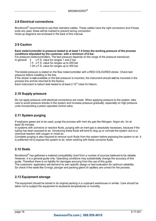
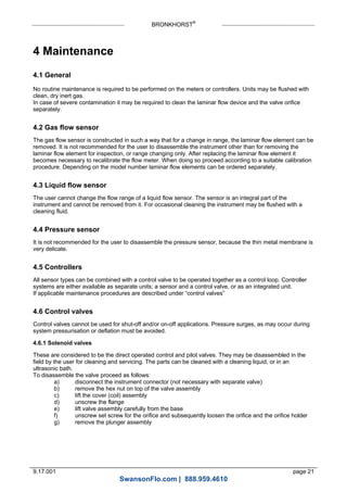
4.7 Kv-value calculation
This calculation method can be used to determine the Kv-value of the main orifice of a control valve.
4.7.1 For gases
Determine desired p across valve.
p must be at least 20% of supply pressure, or in closed loop systems, of total pressure difference in loop.
If p is 20-50% of supply pressure, use formula:
K
T
p p
v
vn n
514 2
under critical
If P is 50-100% of supply pressure, use formula:
K
p
Tv
vn
n
257 1
overcritical
Units:
vn = flow [mn
3
/h]
p1 = supply pressure [bara]
p2 = downstream pressure [bara]
p = pressure difference (p1 - p2) [bard]
T = temperature [K]
n = density [kg/mn
3
]
The orifice diameter can be determined by: d= 7.6 Kv [mm]
4.7.2 For liquids
K
p
v v
1000
Units:
v = volume flow [m3
/h]
= density at 20°C and 1 atm [kg/m3
]
p = delta p [bard]
The orifice bore diameter can be determined by:
d K v 7.6 [mm]
*
SwansonFlo.com | 888.959.4610](https://image.slidesharecdn.com/manual-for-bronkhorst-mass-flow-pressure-meters-and-controllers-for-gases-and-liquids-171025180716/85/Instruction-Manual-for-Bronkhorst-Mass-Flow-Pressure-Meters-and-Controllers-for-Gases-and-Liquids-23-320.jpg)
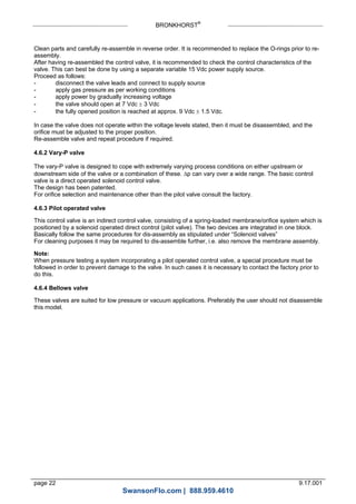
![BRONKHORST®
page 24 9.17.001
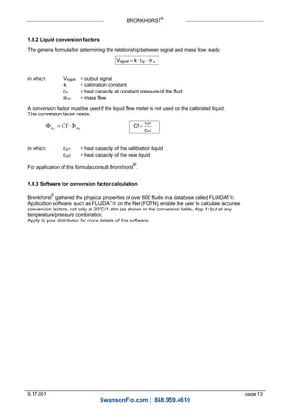
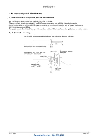
On LFC's only one type of normally closed valve is available. Diameter of orifice can be calculated or looked
up in the table.
Diameter [mm] Kv Normally closed
p max. [bard]
0,10
0,14
0,20
0,30
0,37
0,50
0,70
1,00
1,73 x 10⁻⁴
3,39 x 10⁻⁴
6,93 x 10⁻⁴
1,56 x 10⁻³
2,37 x 10⁻³
4,33 x 10⁻³
8,48 x 10⁻³
1,73 x 10⁻²
10
10
10
10
10
10
10
10
* For liquids having a dynamic viscosity: 15 cP < < 100 cP the Kv value should be calculated according to:
K
p
v v
1000
Units:
v = volume flow [m3
/h]
= density at 20°C and 1 atm. [kg/m3
]
p = delta p [bard]
= dynamic viscosity [cp]
For maximum possible viscosity apply to factory
4.8 Maximum pressure drop
For (pilot) solenoid operated control valves with small orifices the maximum allowable pressure drop for
gases is according to the table.
Diameter [mm] Kv Normally closed
p max. [bard]
Normally opened
p max. [bard]
0,05
0,07
0,10
0,14
0,20
0,30
0,37
0,50
0,70
1,00
1,30
1,50
1,70
2,00
4,33 x 10⁻⁵
8,48 x 10⁻⁵
1,73 x 10⁻⁴
3,39 x 10⁻⁴
6,93 x 10⁻⁴
1,56 x 10⁻³
2,37 x 10⁻³
4,33 x 10⁻³
8,48 x 10⁻³
1,73 x 10⁻²
2,93 x 10⁻²
3,90 x 10⁻²
5,00 x 10⁻²
6,63 x 10⁻²
40
30
30
30
30
30
30
30
24
12
8
6
5
3.6
30
20
20
20
20
20
20
20
15
8
5
n.a.
n.a.
n.a.
For pilot operated valves the maximum pressure drop is limited to 20 bard. If the pressure drop during start-
up is higher, it is preferred to install a bypass valve. During start-up this valve should be opened. Also the
minimum pressure drop is limited. For exact figures consult factory or proceed according to the technical
data and/or additional instructions given by the sales office or department.
SwansonFlo.com | 888.959.4610](https://image.slidesharecdn.com/manual-for-bronkhorst-mass-flow-pressure-meters-and-controllers-for-gases-and-liquids-171025180716/85/Instruction-Manual-for-Bronkhorst-Mass-Flow-Pressure-Meters-and-Controllers-for-Gases-and-Liquids-24-320.jpg)
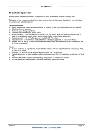

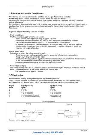
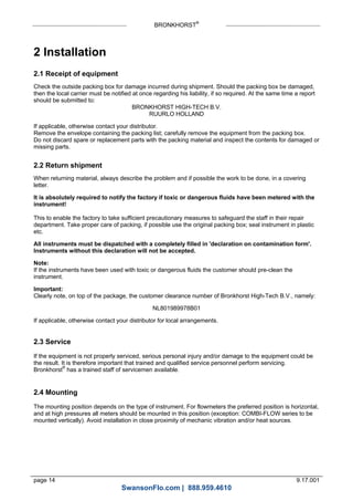
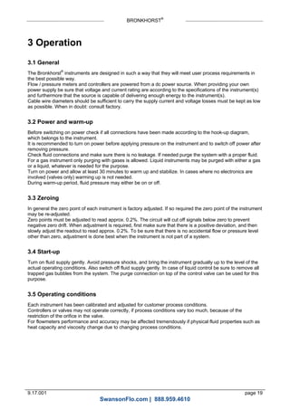
![GAS CONVERSION FACTOR
Nr.: Name: Symbol Density
n g l[ / ]
0°C, 1 atm.
Heat capacity*
c cal cal g Kp [ / . ]
20°C, 1 atm.
Conversion
factor
20°C, 1 atm.
1
2
3
4
5
Acetylene (Ethyne)
Air
Allene (Propadiene)
Ammonia
Argon
C2H2
Air
C3H4
NH3
Ar
1.172
1.293
1.832
0.7693
1.784
0.438
0.241
0.392
0.524
0.125
0.61
1.00
0.43
0.77
1.40
6
7
8
9
10
Arsine
Boron trichloride
Boron trifluoride
Bromine pentafluoride
Butadiene (1,3-)
AsH3
BCl3
BF3
BrF5
C4H6
3.524
5.227
3.044
7.803
2.504
0.133
0.136
0.188
0.156
0.405
0.66
0.44
0.54
0.26
0.31
11
12
13
14
15
Butane
Butene (1-)
Butene (2-) (Cis)
Butene (2-) (Trans)
Carbonylfluoride
C4H10
C4H8
C4H8
C4H8
COF2
2.705
2.581
2.503
2.503
2.983
0.457
0.415
0.387
0.421
0.194
0.25
0.29
0.32
0.30
0.54
16
17
18
19
20
Carbonylsulfide
Carbon dioxide
Carbon disulfide
Carbon monoxide
Chlorine
COS
CO2
CS2
CO
Cl2
2.724
1.977
3.397
1.25
3.218
0.175
0.213
0.152
0.249
0.118
0.65
0.74
0.60
1.00
0.82
21
22
23
24
25
Chlorine trifluoride
Cyanogen
Cyanogen chloride
Cyclopropane
Deuterium
ClF3
C2N2
ClCN
C3H6
D2
4.125
2.376
2.743
1.919
0.1798
0.188
0.275
0.185
0.374
1.73
0.40
0.48
0.61
0.43
1.00
26
27
28
29
30
Diborane
Dibromo difluoromethane
Dichlorosilane
Dimethylamine
Dimethylpropane (2,2-)
B2H6
Br2CF2
SiH2Cl2
C2H6NH
C5H12
1.248
9.361
4.506
2.011
3.219
0.577
0.17
0.17
0.417
0.462
0.43
0.20
0.41
0.37
0.21
31
32
33
34
35
Dimethylether
Disilane
Ethane
Ethylene (Ethene)
Ethylene oxide
C2H6O
Si2H6
C2H6
C2H4
C2H4O
2.105
2.857
1.355
1.261
1.965
0.378
0.352
0.468
0.414
0.303
0.39
0.31
0.49
0.60
0.52
36
37
38
39
40
Ethylacetylene (1-Butyne)
Ethylchloride
Fluorine
Freon-11
Freon-113
C4H6
C2H5Cl
F2
CCl3F
C2Cl3F3
2.413
2.878
1.696
6.129
8.36
0.401
0.263
0.201
0.145
0.174
0.32
0.41
0.91
0.35
0.21
41
42
43
44
45
Freon-1132A
Freon-114
Freon-115
Freon-116
Freon-12
C2H2F2
C2Cl2F4
C2ClF5
C2F6
CCl2F2
2.889
7.626
7.092
6.251
5.547
0.244
0.177
0.182
0.2
0.153
0.44
0.23
0.24
0.25
0.37
46
47
48
49
50
Freon-13
Freon-13B1
Freon-14
Freon-21
Freon-22
CClF3
CBrF3
CF4
CHCl2F
CHClF2
4.72
6.768
3.946
4.592
3.936
0.165
0.12
0.18
0.154
0.168
0.40
0.38
0.44
0.44
0.47
51
52
53
Freon-23
Freon-C318
Germane
CHF3
C4F8
GeH4
3.156
9.372
3.45
0.191
0.222
0.16
0.52
0.15
0.56
* cp - cal (T,p) = cp (T + 50°C, p)
App. 1, page 3
SwansonFlo.com | 888.959.4610](https://image.slidesharecdn.com/manual-for-bronkhorst-mass-flow-pressure-meters-and-controllers-for-gases-and-liquids-171025180716/85/Instruction-Manual-for-Bronkhorst-Mass-Flow-Pressure-Meters-and-Controllers-for-Gases-and-Liquids-29-320.jpg)
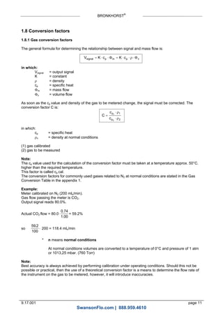
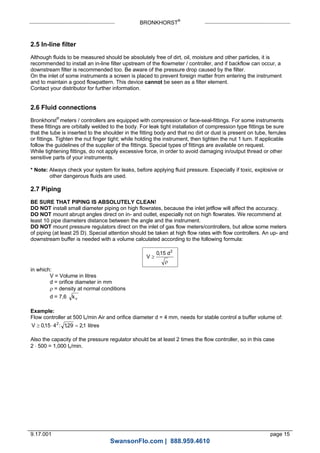
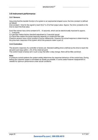
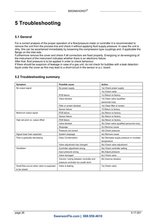
![GAS CONVERSION FACTOR
Nr.: Name: Symbol Density
n g l[ / ]
0°C, 1 atm.
Heat capacity*
c cal cal g Kp [ / . ]
20°C, 1atm.
Conversion
factor
20°C, 1atm.
54
55
56
57
58
Helium
Helium (3-)
Hydrogen
Hydrogen bromide
Hydrogen chloride
He
3He
H2
HBr
HCl
0.1785
0.1346
0.08991
3.646
1.639
1.24
1.606
3.44
0.0869
0.192
1.41
1.44
1.01
0.98
0.99
59
60
61
62
63
Hydrogen cyanide
Hydrogen fluoride
Hydrogen iodide
Hydrogen selenide
Hydrogen sulfide
HCN
HF
HI
H2Se
H2S
1.206
0.8926
5.799
3.663
1.536
0.345
0.362
0.0553
0.109
0.246
0.75
0.96
0.97
0.78
0.82
64
65
66
67
68
Isobutane
Isobutylene (Isobutene)
Krypton
Methane
Methylacetylene
C4H10
C4H8
Kr
CH4
C3H4
2.693
2.60
3.749
0.7175
1.83
0.457
0.429
0.058
0.568
0.399
0.25
0.28
1.43
0.76
0.43
69
70
71
72
73
Methylbromide
Methylchloride
Methylfluoride
Methylmercaptan
Molybdenum hexafluoride
CH3Br
CH3Cl
CH3F
CH3SH
MoF6
4.35
2.3
1.534
2.146
9.366
0.118
0.212
0.29
0.272
0.156
0.61
0.64
0.70
0.53
0.21
74
75
76
77
78
Mono-ethylamine
Monomethylamine
Neon
Nitric oxide
Nitrogen
C2H5NH2
CH3NH2
Ne
NO
N2
2.011
1.419
0.9002
1.34
1.250
0.436
0.424
0.246
0.239
0.249
0.36
0.52
1.41
0.97
1.00
79
80
81
82
83
Nitrogen dioxide
Nitrogen trifluoride
Nitrosyl chloride
Nitrous oxide
Oxygen
NO2
NF3
NOCl
N2O
O2
2.053
3.182
2.984
1.978
1.429
0.204
0.194
0.17
0.221
0.222
0.74
0.50
0.61
0.71
0.98
84
85
86
87
88
Oxygen difluoride
Ozone
Pentane
Perchlorylfluoride
Perfluoropropane
OF2
O3
C5H12
ClO3F
C3F8
2.417
2.154
3.219
4.653
8.662
0.201
0.207
0.455
0.165
0.22
0.64
0.70
0.21
0.41
0.16
89
90
91
92
93
Performa- ethylene
Phosgene
Phosphine
Phosphorous pentafluoride
Propane
C2F4
COCl2
PH3
PF5
C3H8
4.523
4.413
1.53
5.694
2.012
0.206
0.149
0.277
0.183
0.456
0.33
0.47
0.73
0.30
0.34
94
95
96
97
98
Propylene (Propene)
Silane
Silicon tetrafluoride
Sulfurylfluoride
Sulfur dioxide
C3H6
SiH4
SiF4
SO2F2
SO2
1.915
1.443
4.683
4.631
2.922
0.408
0.349
0.18
0.175
0.157
0.40
0.62
0.37
0.38
0.68
99
100
101
102
103
Sulfur hexafluoride
Sulfur tetrafluoride
Trichlorosilane
Trimethylamine
Tungsten hexafluoride
SF6
SF4
SiHCl3
C3H9N
WF6
6.626
4.821
6.044
2.637
13.29
0.175
0.192
0.157
0.424
0.092
0.27
0.34
0.33
0.28
0.25
104
105
106
107
Vinylbromide
Vinylchloride
Vinylfluoride
Xenon
C2H3Br
C2H3Cl
C2H3F
Xe
4.772
2.865
2.08
5.899
0.141
0.229
0.305
0.0382
0.46
0.47
0.49
1.38
* cp - cal (T,p) = cp (T + 50°C, p)
App. 1, page 4
SwansonFlo.com | 888.959.4610](https://image.slidesharecdn.com/manual-for-bronkhorst-mass-flow-pressure-meters-and-controllers-for-gases-and-liquids-171025180716/85/Instruction-Manual-for-Bronkhorst-Mass-Flow-Pressure-Meters-and-Controllers-for-Gases-and-Liquids-30-320.jpg)

The document provides an instruction manual for Mass Flow/Pressure meters and controllers for gases and liquids made by Bronkhorst. It describes the general components of the instruments including different housing styles, sensor principles for measuring gas, liquid and pressure, valve types for flow control, and electronics. The manual also provides guidelines for installation, operation, maintenance, and troubleshooting of the instruments.


