SlideShare a Scribd company logo
1 of 12
Camshaft
A shaftwith one or more cams attached to it, especially one operating the valves
in an internal combustion engine.
Flat vs. Roller:
There are two types of camshafts used in small- and big-block Chevys--flat-tappet
and rollers. Flat-tappet cams use a lifter, sometimes called a follower, that is
essentially flat on the bottom where it rubs on the camshaft lobe. It's actually
slightly crowned in the center for wear reasons, but it looks flat. Roller cams use--
you guessedit--a roller follower and areusually madeof a much hardersteel rather
than a flat-tappet's cast iron. Each of these cam designs can be divided into either
mechanical- or hydraulic-lifter styles. Mechanical, or solid, lifters are justlike they
sound--a solid connection between the lifter and the pushrod. Hydraulic lifters
employ a tiny piston insidea cavity in the lifter. This cavity fills with oil and creates
a hydraulic connection between the lifter and the pushrod. One reason for this
hydraulic connection is to compensate for expansion in the engine parts fromcold
to hot. Now let's get into the camshaft itself.
Lift:
Let's startwith the shapeof the camlobe. Ifyoustartwith a circleand add a "bump"
to a portion of that circle, you've created an eccentric. This is how a camshaft
creates linear (up and down) movement from a rotating device. Lift is defined as
the difference in height between the radius of the circle and the height of the
eccentric. This is called lobe lift. For example, let's say that we use a dial indicator
set on the basecircle of the camlobe. This is the circle area of the lobe. As we turn
the lobe, the dial indicator will begin to rise as it contacts the lobe portion of the
cam. The dial indicator will eventually hit its highest level, let's say 0.340 inch. This
is the lift of that particular lobe. A camshaftfor a small- or big-block V-8 Chevy will
have 16 lobes, one for each intake and exhaust valve in the engine. Most Chevy
cams also come with a fuel pump lobe as well. There are severalways to increase
lift. The easiest way is to use different rocker-arm ratios. For example, the stock
rocker-armratiofor a small-blockis 1.5:1,butseveralcompanies build rockerratios
of 1.6,1.7,and even 1.8:1that can increasevalvelift with the samelobe-lift height.
To determine maximum valve lift, simply multiply the lobe lift by the rocker ratio.
In the case of a 0.340-inch lobelift with a 1.6:1 rocker ratio, this would producea
max theoretical lift 0.544 inch (0.340 x 1.6 = 0.544). We say theoretical because
valve train deflection and tolerance stack-up can prevent the engine from
generating maximum valve lift.
Duration:
If you look at a cam lobe carefully, you'll notice that the lift is created gradually
using a slope. The amount of time (in degrees) that lift is generated is called the
duration of the lobe. Here's where we throw you a mild curve. Camshafts operate
at half engine speed. This is easy to see because the gear that turns the camshaft
is twice the diameter of the crankgear that drivesit. That means thatthe cam spins
at half engine speed. Because of this, camshaft duration is always expressed in
crankshaftdegrees. This makes it easy when it comes time to degree the cam to
ensureit is positioned accurately in the engine. So let's take a typical cam and look
at how duration is expressed. The point at which lobe lift first begins is often
difficult to identify since the profile is very gradual at this point. A long time ago,
the Society of Automotive Engineers (SAE) decided that 0.006 inch of valve lift was
a good place to start, but not all cam manufacturers adhered to that standard.
They choseinstead to use differentheights of >> tappet lift, usually between 0.004
and 0.006 inch. Using 0.004 inch as an example, once lobe lift achieves 0.004 inch,
you startrecording thenumber of crankshaftdegrees ittakes for thelobe to run all
the way through max lift and back to 0.004-inch lobe lift on the closing side. Let's
say this is 270 degrees. This is the advertised duration of the lobe because this is
the number that most cam manufacturers use when referring to their camshaft
duration numbers in advertising.
The problem with advertising numbers was thatnot everyoneused the samelobe-
lift figureto determine duration.This led to significantconfusionwhenit came time
to compare numbers. Legend has it that Harvey Crane suggested that all the cam
manufacturers use0.050inch of tappet lift as a common lobe-lift point that all cam
manufacturers would use so that we could compare the cams. This is the number
that mostpeople usewhen referringto duration specssinceit usesa common data
point. For example, a Crane Power Max278 flat-tappethydraulic has an advertised
duration of 278 degrees on the intake and 290 degrees on the exhaust side. The
duration at 0.050-inchtappetlift is 222degrees on theintake lobe and 234degrees
on the exhaust. Because this camshaft uses different intake and exhaust duration
figures, it is referred to as a dual-pattern cam. If the intake and exhaust durations
are the same, then it would be a single-pattern cam.
We should also go through some information about opening and closing points as
well. Each cam company calls out valve opening and closing points differently. For
example, a Comp Cams timing card will indicate opening and closing points at
0.006inchof tappet lift. Cranedeliversthe opening and closing pointsat both 0.004
inch and 0.050inchoftappet lift. They both usesomeabbreviationsthatyoushould
know.Theintakevalveopens ata given number of degreesBeforeTop Dead Center
(BTDC) and closes the intake After Bottom Dead Center (ABDC). The exhaust valve
generally opens Before Bottom Dead Center (BBDC) and closes After Top Dead
Center (ATDC).
There is a simple way to determine duration. Let's say you havea cam in an engine
and you're not sure of its duration. Set up a degree wheel on the engine and
determine the cam's opening and closing points. Let's say that the intake lobe
opens at 4 degrees BTDC and closes at 44 degrees ABDC, both measured at 0.050
inch of tappet lift. Add the opening and closing points together along with 180
degrees and you will have the cam's duration of 228 degrees at 0.050-inch tappet
lift (4 + 44 + 180 = 228 degrees). This also works for the exhaust side and you can
determine advertised duration the same way. Cool, huh?
Centerlines:
We're not talking about wheels here, but rather the term used to determine the
placement of the lobes both on the cam and in the engine. Let's take intake
centerline first. Each lobe on the camshaft has a centerline, or midpoint in its
duration curve. This would mean that both the intake and exhaust lobes have a
centerline. Camshaft companies place great importance on the intake centerline
for several reasons. Cam companies use the intake centerline of cylinder No. 1 to
establish exactly wherethe camshaftis in relation to the rest of the engine. As you
can imagine, the camshaft must be correctly phased in relationship to the engine
in order to do its job properly. The cam companies use intake centerline as this
reference point. The intake centerline >> is expressed as the number of degrees
ATDC. Generally, the intake centerline will be between 104 and 116 degrees ATDC.
The next item on our centerline agenda is something called lobe separation angle.
This dimension specifies the distance or spread between the intake and exhaust
centerlines. This isimportantbecauseit establishesthe amountof overlapbetween
the intake and exhaust. Overlap is the amount of time (in degrees) that both the
intake and exhaust valves are both open in the cylinder. If you look at the cam-
timing graph above (9), you can see a triangle that forms an area bounded by the
opening side of the intake lobe and the closing side of the exhaust lobe.
If you look at the top of the graph on page 64, you will see two small lines that
indicate the position of the intake- and exhaust-lobe centerlines. The distance
between these two centerlines is the lobe separation angle, expressed in camshaft
degrees. This is the only camspec that is not expressed in crankshaftdegrees. Lobe
separation angle can be determined with somesimple math. For example, let's say
the intake centerline is 106 crankshaftdegrees ATDC and the exhaust centerline is
120 degrees BTDC. Add the two figures and divide by 2 (because we are spinning
the cam half as fast as the crank) to get the lobe separation angle [(106 + 120) / 2
= 113 degrees of lobe separation angle].
Asthe spreadbetween thelobes tightens, the lobe-separationnumber gets smaller
and overlap increases since the centerlines of the two lobes are coming closer
together. A larger lobe separation angle means less overlap because the lobe
centerlines are moving farther apart. This gets tricky because if you increase
duration, this automatically increases the overlap with the same lobe separation
angle. This is why you willsee big cams with wider lobe separation angles since the
cam grinder is attempting to limit the amount of actual overlap between the two
lobes. Ifyoustudy the cam-timing graphfor a while, this conceptwill probablystart
to make sense. Onceyou areclear abouthow this works, you'vetaken a large step
toward understanding how camshafts work.
Conclusion:
There's much more to cams than this shortcoursecan deliver, but these are the
basics of how a cam operates and what all thoseconfusing terms are all about. If
you'veread through this for the firsttime, don't get down on yourself if you don't
fully understand everything we'veoutlined here. Read this story again and work
on each concept before moving on. That will help, and eventually you'll have a
firm grasp on the subject. Then you can use that to amaze and astound your
friends with your incredible knowledgeof that lumpy/bumpy-looking stick that
tickles all the valves.
Crankshaft Bearing
In a piston engine, the main bearings are the bearings on which the crankshaft
rotates, usually plain or journalbearings.
Roller Bearings:
Are frequently pressed onto the crankshaft during assembly. In order to replace
bearings that are fitted in this fashion the crank pin/journal needs to be pressed
out of the counterweight
Plain Bearings:
Split in half and are typically associated with crankcases that can split or support
main bearing caps. This also true of connecting rods on offset/rod journals. Plain
bearings wrap around the journal and are pressurized with oil, the crank journal
'rides' on this layer of oil between the crank journaland the plain bearing. This is
called hydrodynamic lubrication.
Uses
Mainbearing:
The bearings hold the crankshaftin place and prevent the forces created by the
piston and transmitted to the crankshaftby the connecting rods fromdislodging
the crankshaft, instead forcing the crank to convertthe reciprocating movement
into rotation.
Turbocharger and Supercharger
They both are force inductionsystem
They compressed the air fromthe atmosphere and sends it to the engine.
cylinder:
The compressed air allows double amount of fuel to enter into the
cylinder for combustion:
This doubles the power of engine. Turbocharger and supercharger performthe
same operation.
Turbocharger
Itis a forced induction systemthat uses exhaustgases energy to compress the air
formthe atmosphereand sends it to the engine
Cylinder:
The compressed air is rich in oxygen and so the quantity of the fuel entering into
the cylinder is doubled. Now the fuel burnt into the cylinder produces double
power as it was producing without the turbocharger .The turbocharger is not
directly connected to the engine. Itworks moreefficiently on high speed and spins
up to 150000 rpm. It installation is not easy and has complex design as compared
with the supercharger.Itexperiences lag problemdue discontinuousenergysupply
from the exhaust.
Supercharger
It is also a forced induction system that compresses the air and sends it
to the engine cylinder. It is generally placed on the top of the engine and
directly connected to the engine crankshaft for its working. It doubles
the power of engine. They are simple in design and installation. They can
work on low rpm and its spin speed is up to 50,000 rpm. It more reliable
and has negligible lag.
Tappet clearance
Tappet clearance is a spacebetween the top of the valve stem and the rocker arm.
Its purposeis to allow for somemechanical expansion and lengthening of the valve
stemand pushrodsas the engine warmsup. This clearance is also called valvelash.
The term tappet is widely used in relation to internal combustion engines, but
imprecisely. Itis mostcommonly encountered as a maintenance task for overhead
valve engines, that of 'adjusting the tappets. Valves are opened by camshaft lobes
on overhead camshaft engines and by rocker arms on pushrod engines. Loss of
power could be a sign of a weak or broken valve spring, and a tapping noise could
be caused by a loose rocker arm, so a clearance adjustment may not be all that's
needed.
Rocker arm working
A rocker arm (in the context of an internal combustion engine of automotive,
marine, motorcycle and reciprocating aviation types) is an oscillating lever that
conveys radial movement from the cam lobe into linear movement at the poppet
valve to open it.
The cam actuates rocker arms that press down on the valves, opening them.
Springs return the valves to their closed position. These springs have to be very
strong because at high engine speeds, the valves are pushed down very quickly,
and it is the springsthat keep the valvesin contactwith the rockerarms. Therocker
arm of an internal combustion engine changes radial movement into linear
Movement:
This kind of device is properly called a reciprocating lever. It takes the spinning
motion of the overhead camshaft and turns it into the up-and-down movement
that opens and closes the valves. Because they are typically made of steel, rocker
arms havea great deal of strength for their weight, and can thereforeexert a great
deal of leverage.
Cam Lobe:
The camshaftis not a true spherical rod; it has bulges on it called lobes. The lobes
project outward from one side of the shaft, while the back of the shaft opposite
the lobe does not have a projection. As the shaft rotates, the side with the lobe
lifts the outside end of the rocker arm, and then the side without the projection
allows it to fall back. The cam’s movement is transferred to the rocker arm by a
device called a cam follower, of which there are different types that vary by
manufacturerand by vehicle age. Asthe cam shaftspins,the partof the rockerarm
acted upon by the cam follower is lifted and lowered, lifted and lowered.
Valve:
Just as the outside end the cam end of the rocker arm moves up and down, so
does its oppositeside. Asthe camlobe comes roundit lifts the outsideof the rocker
arm, which rocks, and the inner end pushes down on the valve stem, opening it
against its spring. As the lobe rotates away fromthe rocker armthe outsidedrops,
the inner end lifts and the valve’s spring closes it. In this way, the opening and
closing of the valveis kept in sync with the rotation of the camshaft, and thus with
the movementofthe pistons.Collectively, the camlobe, follower,rockerarm,valve
and valve spring are known as the valve train.
Ratio:
Rocker armshaveratios the ratio is a measureof the arm’sleverage, which in turn
determines how powerful the force is that it can transfer to the valve stem. The
ratio is determined by the length of the arm, both between its center of rotation
and the point it contacts the cam lobe, and between its center of rotation and the
top of the valve stem. A typical automotive rocker arm has a 1:1.5 ratio, meaning
that it moves the valve one and a half times further than the peak of the cam lobe
projects up from the camshaft.
Camshaft , Turbocharger and Supercharger, Rocker arm working

More Related Content

What's hot

Valve timing diagram of four stroke diesel engine
Valve timing diagram of four stroke diesel engineValve timing diagram of four stroke diesel engine
Valve timing diagram of four stroke diesel enginerampal singh
 
Valve timing diagrams
Valve timing diagramsValve timing diagrams
Valve timing diagramsluqman ahmed
 
I.C.Engine Valve Timing
I.C.Engine Valve TimingI.C.Engine Valve Timing
I.C.Engine Valve Timingraxit varmora
 
012 Clutches & Bands
012 Clutches & Bands012 Clutches & Bands
012 Clutches & BandsRob Holt
 
Moyno l8 drive end operations and assembly
Moyno l8 drive end operations and assemblyMoyno l8 drive end operations and assembly
Moyno l8 drive end operations and assemblyNelsonBort
 
Case ih 990 agricultural tractor service repair manual
Case ih 990 agricultural tractor service repair manualCase ih 990 agricultural tractor service repair manual
Case ih 990 agricultural tractor service repair manualjfjkskekemm
 
Valve Timing Diagram (2161902) ICE
Valve Timing Diagram (2161902) ICEValve Timing Diagram (2161902) ICE
Valve Timing Diagram (2161902) ICEsaahil kshatriya
 
Halderman ch030 lecture
Halderman ch030 lectureHalderman ch030 lecture
Halderman ch030 lecturemcfalltj
 
Chapter 18
Chapter 18Chapter 18
Chapter 18mcfalltj
 
Port timing and vale timing ppt
Port timing and vale timing pptPort timing and vale timing ppt
Port timing and vale timing pptShãñmükhā Srï
 
Manual mecanica de-motos
Manual mecanica de-motosManual mecanica de-motos
Manual mecanica de-motosMarcos ....
 
Ignition systems page 5
Ignition systems page 5Ignition systems page 5
Ignition systems page 5Rob Ansell
 
Moyno l6 drive end operations and assembly
Moyno l6 drive end operations and assemblyMoyno l6 drive end operations and assembly
Moyno l6 drive end operations and assemblyNelsonBort
 
Hyster c114 (ej1.75 xl europe) forklift service repair manual
Hyster c114 (ej1.75 xl europe) forklift service repair manualHyster c114 (ej1.75 xl europe) forklift service repair manual
Hyster c114 (ej1.75 xl europe) forklift service repair manualufjjsjefkskekmme
 

What's hot (18)

Pump3.
Pump3.Pump3.
Pump3.
 
Valve timing diagram of four stroke diesel engine
Valve timing diagram of four stroke diesel engineValve timing diagram of four stroke diesel engine
Valve timing diagram of four stroke diesel engine
 
Krishna Kotiyal
Krishna KotiyalKrishna Kotiyal
Krishna Kotiyal
 
Valve timing diagrams
Valve timing diagramsValve timing diagrams
Valve timing diagrams
 
I.C.Engine Valve Timing
I.C.Engine Valve TimingI.C.Engine Valve Timing
I.C.Engine Valve Timing
 
012 Clutches & Bands
012 Clutches & Bands012 Clutches & Bands
012 Clutches & Bands
 
Moyno l8 drive end operations and assembly
Moyno l8 drive end operations and assemblyMoyno l8 drive end operations and assembly
Moyno l8 drive end operations and assembly
 
Chap72
Chap72Chap72
Chap72
 
Case ih 990 agricultural tractor service repair manual
Case ih 990 agricultural tractor service repair manualCase ih 990 agricultural tractor service repair manual
Case ih 990 agricultural tractor service repair manual
 
Valve Timing Diagram (2161902) ICE
Valve Timing Diagram (2161902) ICEValve Timing Diagram (2161902) ICE
Valve Timing Diagram (2161902) ICE
 
Halderman ch030 lecture
Halderman ch030 lectureHalderman ch030 lecture
Halderman ch030 lecture
 
Chapter 18
Chapter 18Chapter 18
Chapter 18
 
Port timing and vale timing ppt
Port timing and vale timing pptPort timing and vale timing ppt
Port timing and vale timing ppt
 
Manual de servicio Daewoo Lanos
Manual de servicio Daewoo  LanosManual de servicio Daewoo  Lanos
Manual de servicio Daewoo Lanos
 
Manual mecanica de-motos
Manual mecanica de-motosManual mecanica de-motos
Manual mecanica de-motos
 
Ignition systems page 5
Ignition systems page 5Ignition systems page 5
Ignition systems page 5
 
Moyno l6 drive end operations and assembly
Moyno l6 drive end operations and assemblyMoyno l6 drive end operations and assembly
Moyno l6 drive end operations and assembly
 
Hyster c114 (ej1.75 xl europe) forklift service repair manual
Hyster c114 (ej1.75 xl europe) forklift service repair manualHyster c114 (ej1.75 xl europe) forklift service repair manual
Hyster c114 (ej1.75 xl europe) forklift service repair manual
 

Similar to Camshaft , Turbocharger and Supercharger, Rocker arm working

Chapter 26
Chapter 26Chapter 26
Chapter 26mcfalltj
 
Yamaha ecu Kit YEC_Technical_letter.pdf
Yamaha ecu Kit  YEC_Technical_letter.pdfYamaha ecu Kit  YEC_Technical_letter.pdf
Yamaha ecu Kit YEC_Technical_letter.pdftystar21
 
Ic mid exam n solutn
Ic mid exam n solutnIc mid exam n solutn
Ic mid exam n solutnFasilMelese
 
Distribution systems
Distribution systemsDistribution systems
Distribution systemsEDWINGOTHIC
 
Distribution systems
Distribution systemsDistribution systems
Distribution systemsivanperaza
 
Distribution systems
Distribution systemsDistribution systems
Distribution systemsivanperaza
 
Internal Combustion Engines - Variable valve lift
Internal Combustion Engines - Variable valve liftInternal Combustion Engines - Variable valve lift
Internal Combustion Engines - Variable valve liftRa'uf Tailony
 
FOUR STROKE ENGINE
FOUR STROKE ENGINEFOUR STROKE ENGINE
FOUR STROKE ENGINEshaffu786
 
F22A DSM Turbo install
F22A DSM Turbo installF22A DSM Turbo install
F22A DSM Turbo installShawn Poirier
 
Vst motors report modified
Vst motors report modifiedVst motors report modified
Vst motors report modifiedSolomon Raj
 
Internal Combustion Engine
Internal Combustion EngineInternal Combustion Engine
Internal Combustion EngineAdam Keir
 
Unit 3 : Wheels,Tyre and Braking System
Unit 3 : Wheels,Tyre and Braking SystemUnit 3 : Wheels,Tyre and Braking System
Unit 3 : Wheels,Tyre and Braking SystemVishal Niphade
 
Variable valve timing in internal combustion engine
Variable valve timing in internal combustion engineVariable valve timing in internal combustion engine
Variable valve timing in internal combustion enginerisnathani
 

Similar to Camshaft , Turbocharger and Supercharger, Rocker arm working (20)

Chapter 26
Chapter 26Chapter 26
Chapter 26
 
Yamaha ecu Kit YEC_Technical_letter.pdf
Yamaha ecu Kit  YEC_Technical_letter.pdfYamaha ecu Kit  YEC_Technical_letter.pdf
Yamaha ecu Kit YEC_Technical_letter.pdf
 
Ic mid exam n solutn
Ic mid exam n solutnIc mid exam n solutn
Ic mid exam n solutn
 
Distribution systems
Distribution systemsDistribution systems
Distribution systems
 
Distribution systems
Distribution systemsDistribution systems
Distribution systems
 
Distribution systems
Distribution systemsDistribution systems
Distribution systems
 
Distribution systems
Distribution systemsDistribution systems
Distribution systems
 
Distribution systems
Distribution systemsDistribution systems
Distribution systems
 
Internal Combustion Engines - Variable valve lift
Internal Combustion Engines - Variable valve liftInternal Combustion Engines - Variable valve lift
Internal Combustion Engines - Variable valve lift
 
FOUR STROKE ENGINE
FOUR STROKE ENGINEFOUR STROKE ENGINE
FOUR STROKE ENGINE
 
finalicgt
finalicgtfinalicgt
finalicgt
 
New
NewNew
New
 
F22A DSM Turbo install
F22A DSM Turbo installF22A DSM Turbo install
F22A DSM Turbo install
 
Vst motors report modified
Vst motors report modifiedVst motors report modified
Vst motors report modified
 
UNIT 1.docx
UNIT 1.docxUNIT 1.docx
UNIT 1.docx
 
Internal Combustion Engine
Internal Combustion EngineInternal Combustion Engine
Internal Combustion Engine
 
General Extruder Audit Information
General Extruder Audit InformationGeneral Extruder Audit Information
General Extruder Audit Information
 
Unit 3 : Wheels,Tyre and Braking System
Unit 3 : Wheels,Tyre and Braking SystemUnit 3 : Wheels,Tyre and Braking System
Unit 3 : Wheels,Tyre and Braking System
 
Turbo charger
Turbo chargerTurbo charger
Turbo charger
 
Variable valve timing in internal combustion engine
Variable valve timing in internal combustion engineVariable valve timing in internal combustion engine
Variable valve timing in internal combustion engine
 

More from Salman Jailani

Insulation and Refractories
 Insulation and Refractories Insulation and Refractories
Insulation and RefractoriesSalman Jailani
 
Compressed air_system ( chapter complete )
 Compressed air_system  ( chapter complete ) Compressed air_system  ( chapter complete )
Compressed air_system ( chapter complete )Salman Jailani
 
cooling tower, Factors Affecting Cooling Tower Performance,Efficient System O...
cooling tower, Factors Affecting Cooling Tower Performance,Efficient System O...cooling tower, Factors Affecting Cooling Tower Performance,Efficient System O...
cooling tower, Factors Affecting Cooling Tower Performance,Efficient System O...Salman Jailani
 
Boilers and its types systems and boilers water treatment
Boilers and its types systems and boilers water treatment Boilers and its types systems and boilers water treatment
Boilers and its types systems and boilers water treatment Salman Jailani
 
Global environment concerns
Global environment concernsGlobal environment concerns
Global environment concernsSalman Jailani
 
Energy Resources and Utilization
Energy Resources  and Utilization Energy Resources  and Utilization
Energy Resources and Utilization Salman Jailani
 
Energy management & audit
Energy management & auditEnergy management & audit
Energy management & auditSalman Jailani
 
Machining Technology-2 MT-474 (Practical)
Machining Technology-2 MT-474 (Practical)Machining Technology-2 MT-474 (Practical)
Machining Technology-2 MT-474 (Practical)Salman Jailani
 
Refrigeration and Heat Pump Systems
Refrigeration and Heat Pump SystemsRefrigeration and Heat Pump Systems
Refrigeration and Heat Pump SystemsSalman Jailani
 
Safety Inspections and Sample Safety Inspection.Health and safety training D...
Safety Inspections and Sample Safety Inspection.Health  and safety training D...Safety Inspections and Sample Safety Inspection.Health  and safety training D...
Safety Inspections and Sample Safety Inspection.Health and safety training D...Salman Jailani
 

More from Salman Jailani (20)

Fan and Blowers
 Fan and Blowers Fan and Blowers
Fan and Blowers
 
Insulation and Refractories
 Insulation and Refractories Insulation and Refractories
Insulation and Refractories
 
Furnaces
 Furnaces  Furnaces
Furnaces
 
Compressed air_system ( chapter complete )
 Compressed air_system  ( chapter complete ) Compressed air_system  ( chapter complete )
Compressed air_system ( chapter complete )
 
cooling tower, Factors Affecting Cooling Tower Performance,Efficient System O...
cooling tower, Factors Affecting Cooling Tower Performance,Efficient System O...cooling tower, Factors Affecting Cooling Tower Performance,Efficient System O...
cooling tower, Factors Affecting Cooling Tower Performance,Efficient System O...
 
Boilers and its types systems and boilers water treatment
Boilers and its types systems and boilers water treatment Boilers and its types systems and boilers water treatment
Boilers and its types systems and boilers water treatment
 
Global environment concerns
Global environment concernsGlobal environment concerns
Global environment concerns
 
Energy Resources and Utilization
Energy Resources  and Utilization Energy Resources  and Utilization
Energy Resources and Utilization
 
Energy management
Energy managementEnergy management
Energy management
 
Energy management & audit
Energy management & auditEnergy management & audit
Energy management & audit
 
Steam leakage
Steam leakageSteam leakage
Steam leakage
 
Lab layout
Lab layoutLab layout
Lab layout
 
Lab lay out data
Lab lay out dataLab lay out data
Lab lay out data
 
Machining Technology-2 MT-474 (Practical)
Machining Technology-2 MT-474 (Practical)Machining Technology-2 MT-474 (Practical)
Machining Technology-2 MT-474 (Practical)
 
Lab report title
Lab report title Lab report title
Lab report title
 
Refrigeration and Heat Pump Systems
Refrigeration and Heat Pump SystemsRefrigeration and Heat Pump Systems
Refrigeration and Heat Pump Systems
 
Safety Inspections and Sample Safety Inspection.Health and safety training D...
Safety Inspections and Sample Safety Inspection.Health  and safety training D...Safety Inspections and Sample Safety Inspection.Health  and safety training D...
Safety Inspections and Sample Safety Inspection.Health and safety training D...
 
Cnc turning
Cnc turning Cnc turning
Cnc turning
 
Cnc milling turning
Cnc milling turning Cnc milling turning
Cnc milling turning
 
CNC machining centers
CNC machining centersCNC machining centers
CNC machining centers
 

Recently uploaded

Structural Analysis and Design of Foundations: A Comprehensive Handbook for S...
Structural Analysis and Design of Foundations: A Comprehensive Handbook for S...Structural Analysis and Design of Foundations: A Comprehensive Handbook for S...
Structural Analysis and Design of Foundations: A Comprehensive Handbook for S...Dr.Costas Sachpazis
 
Intze Overhead Water Tank Design by Working Stress - IS Method.pdf
Intze Overhead Water Tank  Design by Working Stress - IS Method.pdfIntze Overhead Water Tank  Design by Working Stress - IS Method.pdf
Intze Overhead Water Tank Design by Working Stress - IS Method.pdfSuman Jyoti
 
VIP Model Call Girls Kothrud ( Pune ) Call ON 8005736733 Starting From 5K to ...
VIP Model Call Girls Kothrud ( Pune ) Call ON 8005736733 Starting From 5K to ...VIP Model Call Girls Kothrud ( Pune ) Call ON 8005736733 Starting From 5K to ...
VIP Model Call Girls Kothrud ( Pune ) Call ON 8005736733 Starting From 5K to ...SUHANI PANDEY
 
chapter 5.pptx: drainage and irrigation engineering
chapter 5.pptx: drainage and irrigation engineeringchapter 5.pptx: drainage and irrigation engineering
chapter 5.pptx: drainage and irrigation engineeringmulugeta48
 
Call for Papers - International Journal of Intelligent Systems and Applicatio...
Call for Papers - International Journal of Intelligent Systems and Applicatio...Call for Papers - International Journal of Intelligent Systems and Applicatio...
Call for Papers - International Journal of Intelligent Systems and Applicatio...Christo Ananth
 
The Most Attractive Pune Call Girls Budhwar Peth 8250192130 Will You Miss Thi...
The Most Attractive Pune Call Girls Budhwar Peth 8250192130 Will You Miss Thi...The Most Attractive Pune Call Girls Budhwar Peth 8250192130 Will You Miss Thi...
The Most Attractive Pune Call Girls Budhwar Peth 8250192130 Will You Miss Thi...ranjana rawat
 
Unit 1 - Soil Classification and Compaction.pdf
Unit 1 - Soil Classification and Compaction.pdfUnit 1 - Soil Classification and Compaction.pdf
Unit 1 - Soil Classification and Compaction.pdfRagavanV2
 
Online banking management system project.pdf
Online banking management system project.pdfOnline banking management system project.pdf
Online banking management system project.pdfKamal Acharya
 
Call Girls Pimpri Chinchwad Call Me 7737669865 Budget Friendly No Advance Boo...
Call Girls Pimpri Chinchwad Call Me 7737669865 Budget Friendly No Advance Boo...Call Girls Pimpri Chinchwad Call Me 7737669865 Budget Friendly No Advance Boo...
Call Girls Pimpri Chinchwad Call Me 7737669865 Budget Friendly No Advance Boo...roncy bisnoi
 
UNIT-V FMM.HYDRAULIC TURBINE - Construction and working
UNIT-V FMM.HYDRAULIC TURBINE - Construction and workingUNIT-V FMM.HYDRAULIC TURBINE - Construction and working
UNIT-V FMM.HYDRAULIC TURBINE - Construction and workingrknatarajan
 
data_management_and _data_science_cheat_sheet.pdf
data_management_and _data_science_cheat_sheet.pdfdata_management_and _data_science_cheat_sheet.pdf
data_management_and _data_science_cheat_sheet.pdfJiananWang21
 
Double rodded leveling 1 pdf activity 01
Double rodded leveling 1 pdf activity 01Double rodded leveling 1 pdf activity 01
Double rodded leveling 1 pdf activity 01KreezheaRecto
 
Call for Papers - African Journal of Biological Sciences, E-ISSN: 2663-2187, ...
Call for Papers - African Journal of Biological Sciences, E-ISSN: 2663-2187, ...Call for Papers - African Journal of Biological Sciences, E-ISSN: 2663-2187, ...
Call for Papers - African Journal of Biological Sciences, E-ISSN: 2663-2187, ...Christo Ananth
 
BSides Seattle 2024 - Stopping Ethan Hunt From Taking Your Data.pptx
BSides Seattle 2024 - Stopping Ethan Hunt From Taking Your Data.pptxBSides Seattle 2024 - Stopping Ethan Hunt From Taking Your Data.pptx
BSides Seattle 2024 - Stopping Ethan Hunt From Taking Your Data.pptxfenichawla
 
Thermal Engineering -unit - III & IV.ppt
Thermal Engineering -unit - III & IV.pptThermal Engineering -unit - III & IV.ppt
Thermal Engineering -unit - III & IV.pptDineshKumar4165
 
Booking open Available Pune Call Girls Koregaon Park 6297143586 Call Hot Ind...
Booking open Available Pune Call Girls Koregaon Park  6297143586 Call Hot Ind...Booking open Available Pune Call Girls Koregaon Park  6297143586 Call Hot Ind...
Booking open Available Pune Call Girls Koregaon Park 6297143586 Call Hot Ind...Call Girls in Nagpur High Profile
 
Top Rated Pune Call Girls Budhwar Peth ⟟ 6297143586 ⟟ Call Me For Genuine Se...
Top Rated  Pune Call Girls Budhwar Peth ⟟ 6297143586 ⟟ Call Me For Genuine Se...Top Rated  Pune Call Girls Budhwar Peth ⟟ 6297143586 ⟟ Call Me For Genuine Se...
Top Rated Pune Call Girls Budhwar Peth ⟟ 6297143586 ⟟ Call Me For Genuine Se...Call Girls in Nagpur High Profile
 
Call Girls Walvekar Nagar Call Me 7737669865 Budget Friendly No Advance Booking
Call Girls Walvekar Nagar Call Me 7737669865 Budget Friendly No Advance BookingCall Girls Walvekar Nagar Call Me 7737669865 Budget Friendly No Advance Booking
Call Girls Walvekar Nagar Call Me 7737669865 Budget Friendly No Advance Bookingroncy bisnoi
 
KubeKraft presentation @CloudNativeHooghly
KubeKraft presentation @CloudNativeHooghlyKubeKraft presentation @CloudNativeHooghly
KubeKraft presentation @CloudNativeHooghlysanyuktamishra911
 

Recently uploaded (20)

Structural Analysis and Design of Foundations: A Comprehensive Handbook for S...
Structural Analysis and Design of Foundations: A Comprehensive Handbook for S...Structural Analysis and Design of Foundations: A Comprehensive Handbook for S...
Structural Analysis and Design of Foundations: A Comprehensive Handbook for S...
 
Intze Overhead Water Tank Design by Working Stress - IS Method.pdf
Intze Overhead Water Tank  Design by Working Stress - IS Method.pdfIntze Overhead Water Tank  Design by Working Stress - IS Method.pdf
Intze Overhead Water Tank Design by Working Stress - IS Method.pdf
 
VIP Model Call Girls Kothrud ( Pune ) Call ON 8005736733 Starting From 5K to ...
VIP Model Call Girls Kothrud ( Pune ) Call ON 8005736733 Starting From 5K to ...VIP Model Call Girls Kothrud ( Pune ) Call ON 8005736733 Starting From 5K to ...
VIP Model Call Girls Kothrud ( Pune ) Call ON 8005736733 Starting From 5K to ...
 
chapter 5.pptx: drainage and irrigation engineering
chapter 5.pptx: drainage and irrigation engineeringchapter 5.pptx: drainage and irrigation engineering
chapter 5.pptx: drainage and irrigation engineering
 
Call for Papers - International Journal of Intelligent Systems and Applicatio...
Call for Papers - International Journal of Intelligent Systems and Applicatio...Call for Papers - International Journal of Intelligent Systems and Applicatio...
Call for Papers - International Journal of Intelligent Systems and Applicatio...
 
The Most Attractive Pune Call Girls Budhwar Peth 8250192130 Will You Miss Thi...
The Most Attractive Pune Call Girls Budhwar Peth 8250192130 Will You Miss Thi...The Most Attractive Pune Call Girls Budhwar Peth 8250192130 Will You Miss Thi...
The Most Attractive Pune Call Girls Budhwar Peth 8250192130 Will You Miss Thi...
 
Unit 1 - Soil Classification and Compaction.pdf
Unit 1 - Soil Classification and Compaction.pdfUnit 1 - Soil Classification and Compaction.pdf
Unit 1 - Soil Classification and Compaction.pdf
 
Online banking management system project.pdf
Online banking management system project.pdfOnline banking management system project.pdf
Online banking management system project.pdf
 
Call Girls Pimpri Chinchwad Call Me 7737669865 Budget Friendly No Advance Boo...
Call Girls Pimpri Chinchwad Call Me 7737669865 Budget Friendly No Advance Boo...Call Girls Pimpri Chinchwad Call Me 7737669865 Budget Friendly No Advance Boo...
Call Girls Pimpri Chinchwad Call Me 7737669865 Budget Friendly No Advance Boo...
 
UNIT-V FMM.HYDRAULIC TURBINE - Construction and working
UNIT-V FMM.HYDRAULIC TURBINE - Construction and workingUNIT-V FMM.HYDRAULIC TURBINE - Construction and working
UNIT-V FMM.HYDRAULIC TURBINE - Construction and working
 
data_management_and _data_science_cheat_sheet.pdf
data_management_and _data_science_cheat_sheet.pdfdata_management_and _data_science_cheat_sheet.pdf
data_management_and _data_science_cheat_sheet.pdf
 
Double rodded leveling 1 pdf activity 01
Double rodded leveling 1 pdf activity 01Double rodded leveling 1 pdf activity 01
Double rodded leveling 1 pdf activity 01
 
Call for Papers - African Journal of Biological Sciences, E-ISSN: 2663-2187, ...
Call for Papers - African Journal of Biological Sciences, E-ISSN: 2663-2187, ...Call for Papers - African Journal of Biological Sciences, E-ISSN: 2663-2187, ...
Call for Papers - African Journal of Biological Sciences, E-ISSN: 2663-2187, ...
 
BSides Seattle 2024 - Stopping Ethan Hunt From Taking Your Data.pptx
BSides Seattle 2024 - Stopping Ethan Hunt From Taking Your Data.pptxBSides Seattle 2024 - Stopping Ethan Hunt From Taking Your Data.pptx
BSides Seattle 2024 - Stopping Ethan Hunt From Taking Your Data.pptx
 
Call Girls in Ramesh Nagar Delhi 💯 Call Us 🔝9953056974 🔝 Escort Service
Call Girls in Ramesh Nagar Delhi 💯 Call Us 🔝9953056974 🔝 Escort ServiceCall Girls in Ramesh Nagar Delhi 💯 Call Us 🔝9953056974 🔝 Escort Service
Call Girls in Ramesh Nagar Delhi 💯 Call Us 🔝9953056974 🔝 Escort Service
 
Thermal Engineering -unit - III & IV.ppt
Thermal Engineering -unit - III & IV.pptThermal Engineering -unit - III & IV.ppt
Thermal Engineering -unit - III & IV.ppt
 
Booking open Available Pune Call Girls Koregaon Park 6297143586 Call Hot Ind...
Booking open Available Pune Call Girls Koregaon Park  6297143586 Call Hot Ind...Booking open Available Pune Call Girls Koregaon Park  6297143586 Call Hot Ind...
Booking open Available Pune Call Girls Koregaon Park 6297143586 Call Hot Ind...
 
Top Rated Pune Call Girls Budhwar Peth ⟟ 6297143586 ⟟ Call Me For Genuine Se...
Top Rated  Pune Call Girls Budhwar Peth ⟟ 6297143586 ⟟ Call Me For Genuine Se...Top Rated  Pune Call Girls Budhwar Peth ⟟ 6297143586 ⟟ Call Me For Genuine Se...
Top Rated Pune Call Girls Budhwar Peth ⟟ 6297143586 ⟟ Call Me For Genuine Se...
 
Call Girls Walvekar Nagar Call Me 7737669865 Budget Friendly No Advance Booking
Call Girls Walvekar Nagar Call Me 7737669865 Budget Friendly No Advance BookingCall Girls Walvekar Nagar Call Me 7737669865 Budget Friendly No Advance Booking
Call Girls Walvekar Nagar Call Me 7737669865 Budget Friendly No Advance Booking
 
KubeKraft presentation @CloudNativeHooghly
KubeKraft presentation @CloudNativeHooghlyKubeKraft presentation @CloudNativeHooghly
KubeKraft presentation @CloudNativeHooghly
 

Camshaft , Turbocharger and Supercharger, Rocker arm working

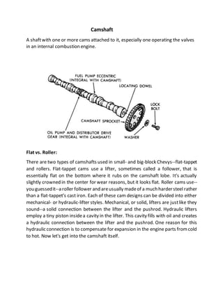
  • 1. Camshaft A shaftwith one or more cams attached to it, especially one operating the valves in an internal combustion engine. Flat vs. Roller: There are two types of camshafts used in small- and big-block Chevys--flat-tappet and rollers. Flat-tappet cams use a lifter, sometimes called a follower, that is essentially flat on the bottom where it rubs on the camshaft lobe. It's actually slightly crowned in the center for wear reasons, but it looks flat. Roller cams use-- you guessedit--a roller follower and areusually madeof a much hardersteel rather than a flat-tappet's cast iron. Each of these cam designs can be divided into either mechanical- or hydraulic-lifter styles. Mechanical, or solid, lifters are justlike they sound--a solid connection between the lifter and the pushrod. Hydraulic lifters employ a tiny piston insidea cavity in the lifter. This cavity fills with oil and creates a hydraulic connection between the lifter and the pushrod. One reason for this hydraulic connection is to compensate for expansion in the engine parts fromcold to hot. Now let's get into the camshaft itself.
  • 2. Lift: Let's startwith the shapeof the camlobe. Ifyoustartwith a circleand add a "bump" to a portion of that circle, you've created an eccentric. This is how a camshaft creates linear (up and down) movement from a rotating device. Lift is defined as the difference in height between the radius of the circle and the height of the eccentric. This is called lobe lift. For example, let's say that we use a dial indicator set on the basecircle of the camlobe. This is the circle area of the lobe. As we turn the lobe, the dial indicator will begin to rise as it contacts the lobe portion of the cam. The dial indicator will eventually hit its highest level, let's say 0.340 inch. This is the lift of that particular lobe. A camshaftfor a small- or big-block V-8 Chevy will have 16 lobes, one for each intake and exhaust valve in the engine. Most Chevy cams also come with a fuel pump lobe as well. There are severalways to increase lift. The easiest way is to use different rocker-arm ratios. For example, the stock rocker-armratiofor a small-blockis 1.5:1,butseveralcompanies build rockerratios of 1.6,1.7,and even 1.8:1that can increasevalvelift with the samelobe-lift height. To determine maximum valve lift, simply multiply the lobe lift by the rocker ratio. In the case of a 0.340-inch lobelift with a 1.6:1 rocker ratio, this would producea max theoretical lift 0.544 inch (0.340 x 1.6 = 0.544). We say theoretical because valve train deflection and tolerance stack-up can prevent the engine from generating maximum valve lift. Duration: If you look at a cam lobe carefully, you'll notice that the lift is created gradually using a slope. The amount of time (in degrees) that lift is generated is called the duration of the lobe. Here's where we throw you a mild curve. Camshafts operate at half engine speed. This is easy to see because the gear that turns the camshaft is twice the diameter of the crankgear that drivesit. That means thatthe cam spins at half engine speed. Because of this, camshaft duration is always expressed in crankshaftdegrees. This makes it easy when it comes time to degree the cam to ensureit is positioned accurately in the engine. So let's take a typical cam and look at how duration is expressed. The point at which lobe lift first begins is often difficult to identify since the profile is very gradual at this point. A long time ago, the Society of Automotive Engineers (SAE) decided that 0.006 inch of valve lift was a good place to start, but not all cam manufacturers adhered to that standard.
  • 3. They choseinstead to use differentheights of >> tappet lift, usually between 0.004 and 0.006 inch. Using 0.004 inch as an example, once lobe lift achieves 0.004 inch, you startrecording thenumber of crankshaftdegrees ittakes for thelobe to run all the way through max lift and back to 0.004-inch lobe lift on the closing side. Let's say this is 270 degrees. This is the advertised duration of the lobe because this is the number that most cam manufacturers use when referring to their camshaft duration numbers in advertising. The problem with advertising numbers was thatnot everyoneused the samelobe- lift figureto determine duration.This led to significantconfusionwhenit came time to compare numbers. Legend has it that Harvey Crane suggested that all the cam manufacturers use0.050inch of tappet lift as a common lobe-lift point that all cam manufacturers would use so that we could compare the cams. This is the number that mostpeople usewhen referringto duration specssinceit usesa common data point. For example, a Crane Power Max278 flat-tappethydraulic has an advertised duration of 278 degrees on the intake and 290 degrees on the exhaust side. The duration at 0.050-inchtappetlift is 222degrees on theintake lobe and 234degrees on the exhaust. Because this camshaft uses different intake and exhaust duration figures, it is referred to as a dual-pattern cam. If the intake and exhaust durations are the same, then it would be a single-pattern cam. We should also go through some information about opening and closing points as well. Each cam company calls out valve opening and closing points differently. For example, a Comp Cams timing card will indicate opening and closing points at 0.006inchof tappet lift. Cranedeliversthe opening and closing pointsat both 0.004 inch and 0.050inchoftappet lift. They both usesomeabbreviationsthatyoushould know.Theintakevalveopens ata given number of degreesBeforeTop Dead Center (BTDC) and closes the intake After Bottom Dead Center (ABDC). The exhaust valve generally opens Before Bottom Dead Center (BBDC) and closes After Top Dead Center (ATDC). There is a simple way to determine duration. Let's say you havea cam in an engine and you're not sure of its duration. Set up a degree wheel on the engine and determine the cam's opening and closing points. Let's say that the intake lobe opens at 4 degrees BTDC and closes at 44 degrees ABDC, both measured at 0.050
  • 4. inch of tappet lift. Add the opening and closing points together along with 180 degrees and you will have the cam's duration of 228 degrees at 0.050-inch tappet lift (4 + 44 + 180 = 228 degrees). This also works for the exhaust side and you can determine advertised duration the same way. Cool, huh? Centerlines: We're not talking about wheels here, but rather the term used to determine the placement of the lobes both on the cam and in the engine. Let's take intake centerline first. Each lobe on the camshaft has a centerline, or midpoint in its duration curve. This would mean that both the intake and exhaust lobes have a centerline. Camshaft companies place great importance on the intake centerline for several reasons. Cam companies use the intake centerline of cylinder No. 1 to establish exactly wherethe camshaftis in relation to the rest of the engine. As you can imagine, the camshaft must be correctly phased in relationship to the engine in order to do its job properly. The cam companies use intake centerline as this reference point. The intake centerline >> is expressed as the number of degrees ATDC. Generally, the intake centerline will be between 104 and 116 degrees ATDC. The next item on our centerline agenda is something called lobe separation angle. This dimension specifies the distance or spread between the intake and exhaust centerlines. This isimportantbecauseit establishesthe amountof overlapbetween the intake and exhaust. Overlap is the amount of time (in degrees) that both the intake and exhaust valves are both open in the cylinder. If you look at the cam- timing graph above (9), you can see a triangle that forms an area bounded by the opening side of the intake lobe and the closing side of the exhaust lobe. If you look at the top of the graph on page 64, you will see two small lines that indicate the position of the intake- and exhaust-lobe centerlines. The distance between these two centerlines is the lobe separation angle, expressed in camshaft degrees. This is the only camspec that is not expressed in crankshaftdegrees. Lobe separation angle can be determined with somesimple math. For example, let's say the intake centerline is 106 crankshaftdegrees ATDC and the exhaust centerline is 120 degrees BTDC. Add the two figures and divide by 2 (because we are spinning the cam half as fast as the crank) to get the lobe separation angle [(106 + 120) / 2 = 113 degrees of lobe separation angle].
  • 5. Asthe spreadbetween thelobes tightens, the lobe-separationnumber gets smaller and overlap increases since the centerlines of the two lobes are coming closer together. A larger lobe separation angle means less overlap because the lobe centerlines are moving farther apart. This gets tricky because if you increase duration, this automatically increases the overlap with the same lobe separation angle. This is why you willsee big cams with wider lobe separation angles since the cam grinder is attempting to limit the amount of actual overlap between the two lobes. Ifyoustudy the cam-timing graphfor a while, this conceptwill probablystart to make sense. Onceyou areclear abouthow this works, you'vetaken a large step toward understanding how camshafts work. Conclusion: There's much more to cams than this shortcoursecan deliver, but these are the basics of how a cam operates and what all thoseconfusing terms are all about. If you'veread through this for the firsttime, don't get down on yourself if you don't fully understand everything we'veoutlined here. Read this story again and work on each concept before moving on. That will help, and eventually you'll have a firm grasp on the subject. Then you can use that to amaze and astound your friends with your incredible knowledgeof that lumpy/bumpy-looking stick that tickles all the valves. Crankshaft Bearing In a piston engine, the main bearings are the bearings on which the crankshaft rotates, usually plain or journalbearings.
  • 6. Roller Bearings: Are frequently pressed onto the crankshaft during assembly. In order to replace bearings that are fitted in this fashion the crank pin/journal needs to be pressed out of the counterweight Plain Bearings: Split in half and are typically associated with crankcases that can split or support main bearing caps. This also true of connecting rods on offset/rod journals. Plain bearings wrap around the journal and are pressurized with oil, the crank journal 'rides' on this layer of oil between the crank journaland the plain bearing. This is called hydrodynamic lubrication.
  • 7. Uses Mainbearing: The bearings hold the crankshaftin place and prevent the forces created by the piston and transmitted to the crankshaftby the connecting rods fromdislodging the crankshaft, instead forcing the crank to convertthe reciprocating movement into rotation. Turbocharger and Supercharger They both are force inductionsystem They compressed the air fromthe atmosphere and sends it to the engine. cylinder: The compressed air allows double amount of fuel to enter into the cylinder for combustion: This doubles the power of engine. Turbocharger and supercharger performthe same operation.
  • 8. Turbocharger Itis a forced induction systemthat uses exhaustgases energy to compress the air formthe atmosphereand sends it to the engine Cylinder: The compressed air is rich in oxygen and so the quantity of the fuel entering into the cylinder is doubled. Now the fuel burnt into the cylinder produces double power as it was producing without the turbocharger .The turbocharger is not directly connected to the engine. Itworks moreefficiently on high speed and spins up to 150000 rpm. It installation is not easy and has complex design as compared with the supercharger.Itexperiences lag problemdue discontinuousenergysupply from the exhaust.
  • 9. Supercharger It is also a forced induction system that compresses the air and sends it to the engine cylinder. It is generally placed on the top of the engine and directly connected to the engine crankshaft for its working. It doubles the power of engine. They are simple in design and installation. They can work on low rpm and its spin speed is up to 50,000 rpm. It more reliable and has negligible lag. Tappet clearance Tappet clearance is a spacebetween the top of the valve stem and the rocker arm. Its purposeis to allow for somemechanical expansion and lengthening of the valve stemand pushrodsas the engine warmsup. This clearance is also called valvelash.
  • 10. The term tappet is widely used in relation to internal combustion engines, but imprecisely. Itis mostcommonly encountered as a maintenance task for overhead valve engines, that of 'adjusting the tappets. Valves are opened by camshaft lobes on overhead camshaft engines and by rocker arms on pushrod engines. Loss of power could be a sign of a weak or broken valve spring, and a tapping noise could be caused by a loose rocker arm, so a clearance adjustment may not be all that's needed. Rocker arm working A rocker arm (in the context of an internal combustion engine of automotive, marine, motorcycle and reciprocating aviation types) is an oscillating lever that conveys radial movement from the cam lobe into linear movement at the poppet valve to open it. The cam actuates rocker arms that press down on the valves, opening them. Springs return the valves to their closed position. These springs have to be very strong because at high engine speeds, the valves are pushed down very quickly, and it is the springsthat keep the valvesin contactwith the rockerarms. Therocker arm of an internal combustion engine changes radial movement into linear
  • 11. Movement: This kind of device is properly called a reciprocating lever. It takes the spinning motion of the overhead camshaft and turns it into the up-and-down movement that opens and closes the valves. Because they are typically made of steel, rocker arms havea great deal of strength for their weight, and can thereforeexert a great deal of leverage. Cam Lobe: The camshaftis not a true spherical rod; it has bulges on it called lobes. The lobes project outward from one side of the shaft, while the back of the shaft opposite the lobe does not have a projection. As the shaft rotates, the side with the lobe lifts the outside end of the rocker arm, and then the side without the projection allows it to fall back. The cam’s movement is transferred to the rocker arm by a device called a cam follower, of which there are different types that vary by manufacturerand by vehicle age. Asthe cam shaftspins,the partof the rockerarm acted upon by the cam follower is lifted and lowered, lifted and lowered. Valve: Just as the outside end the cam end of the rocker arm moves up and down, so does its oppositeside. Asthe camlobe comes roundit lifts the outsideof the rocker arm, which rocks, and the inner end pushes down on the valve stem, opening it against its spring. As the lobe rotates away fromthe rocker armthe outsidedrops, the inner end lifts and the valve’s spring closes it. In this way, the opening and closing of the valveis kept in sync with the rotation of the camshaft, and thus with the movementofthe pistons.Collectively, the camlobe, follower,rockerarm,valve and valve spring are known as the valve train. Ratio: Rocker armshaveratios the ratio is a measureof the arm’sleverage, which in turn determines how powerful the force is that it can transfer to the valve stem. The ratio is determined by the length of the arm, both between its center of rotation and the point it contacts the cam lobe, and between its center of rotation and the top of the valve stem. A typical automotive rocker arm has a 1:1.5 ratio, meaning that it moves the valve one and a half times further than the peak of the cam lobe projects up from the camshaft.