Heat Transfer Analysis for a Winged Reentry Flight Test Bed
X-69
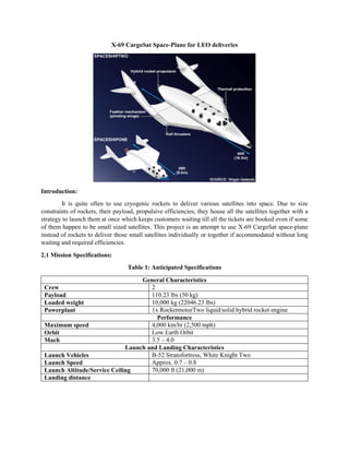
1. X-69 CargoSat Space-Plane for LEO deliveries
Introduction:
It is quite often to use cryogenic rockets to deliver various satellites into space. Due to size
constraints of rockets, their payload, propulsive efficiencies, they house all the satellites together with a
strategy to launch them at once which keeps customers waiting till all the tickets are booked even if some
of them happen to be small sized satellites. This project is an attempt to use X-69 CargoSat space-plane
instead of rockets to deliver those small satellites individually or together if accommodated without long
waiting and required efficiencies.
2.1 Mission Specifications:
Table 1: Anticipated Specifications
General Characteristics
Crew 2
Payload 110.23 lbs (50 kg)
Loaded weight 10,000 kg (22046.23 lbs)
Powerplant 1x RocketmotorTwo liquid/solid hybrid rocket engine
Performance
Maximum speed 4,000 km/hr (2,500 mph)
Orbit Low Earth Orbit
Mach 3.5 – 4.0
Launch and Landing Characteristics
Launch Vehicles B-52 Stratofortress, White Knight Two
Launch Speed Approx. 0.7 – 0.8
Launch Altitude/Service Ceiling 70,000 ft (21,000 m)
Landing distance
2. 2.2 Mission Profile:
Mission profile for X-69 will look similar to that of X-15 as shown in Fig. 1. There will be
modifications after X-69 dives into the space, although its in-atmosphere is similar to that of X-15. Any
mothership will help to air launch X-69. After detachment, it will burnout and climb towards LEO using
RocketMotorTwo engine or similar ones.
Fig 2. shows anticipated mission profile of X-69 CargoSat. Depending on mission it may spend
variable amount of time in space either to just deploy and or wait for docking back another satellite. Re-
entry will initiated as it drops into the atmosphere and will glide and land on airport.
Fig. 1. Mission Profile of X-15
3. Fig 2. Estimated Mission profile of X-69 CargoSat
2.3 Market Analysis:
Since a decade, concept of cubesats and other small satellites has been trending with a rising market.
They deliver crucial advantages like compactness, multifunctional characteristics due to advanced
technologies and highly efficient features. To date, rockets have been used to deliver these satellites into
the space or orbits. Rockets are good to transport heavy and large instruments into the space. Although if a
company or a customer wants to put their small-sized satellites to space, they have to wait or pay more price
if they seek to launch through rockets. Moreover, it keeps them waiting till all other satellite companies
collaborate for launch.
4. Reusable space-planes have capabilities to reach up to LEO and further. Small satellites can be
delivered into space by space-planes with reusable capabilities. X-planes like Virgin Galactic’s Spaceship
Two, X-15, X-37B can make return trips with crew inside.
2.4 Technical and Economic Feasibility
Space-planes carrying human to space have been under research and even been flown quite many
times. From technical perspective, it would be feasible to re-design the space-planes for satellite transport
with reusability which essentially gives the benefit for aborted missions. These planes can also be used to
bring back damaged or reparable satellites with efficient re-entry. Following points can be considered to
propose the design of X-69 CargoSat:
Based on payload and other avionics features, the design of X-69 will be similar to that been
trending for Space-planes for human space flight.
Air-launch will be same, using either B-52 Stratofortress or White Knight Two aircrafts.
Will have to re-consider the aerodynamics for re-entry and landing aspects.
Propulsion system will change based on payload, carrying satellites back and forth.
Reusability is always an advantage for space transportation. Moreover, many attempts have been
made and some of them are even successful to bring back rockets from space like SpaceX and Blue Origin.
Although, this takes lot of fuel to fight with re-entry speeds and again to manage a perfect landing. It is
quite easy for an airplane-like structure to land with less maintenance and accuracy. Again, space-planes
would not need specific launch/landing pad. If X-69 brings reparable satellites from space, it can be
delivered wherever it is necessary with less earth-transportation issues. It can land on any airport, deliver
the satellite.
For instance, let’s say a Chinese Space agency collaborates and asks American space agency who
makes X-69 to bring back their damaged satellite, it will be easy and feasible to rendezvous X-69 to that
satellite, dock it in, re-enter and land on any airport in China delivering the payload and flying back to home
country. This will reduce ground transport cost, will not have to about damaged satellites and many other
advantages.
2.5 Critical Mission Requirements:
Following are the critical mission requirements that should be considered for design:
Delta-wing design for re-entry and efficient landing.
Efficient propulsion system for X-69 while air launching.
Outer body material to deal with re-entry heat and high temperatures.
Delta-wing pattern is quite traditional for supersonic aircrafts. Its design depends on requirements
of aircraft and other technical specifications like altitude, speed, take-off and landing distance etc. Due to
hypersonic speeds at re-entry, the surround atmospheric air heats up which is unfavorable for aircrafts with
normal body material. Using carbon-composite makes it light-weight, resistant to high temperature and
pressure and many other structural advantages.
5. 3.0 Comparative Study of Similar Airplanes:
Table 2: Comparative study
Parameters X-69 CargoSat Virgin Galactic’s
Spaceship Two
Boeing’s X-37 Boeing’s X-20
Dyna-Soar
X-15
Crew 2 2 crew and 6
passengers
none 1 pilot 1 pilot
Takeoff/Launch
weight
22,000 lb 21,428 lb (9,740 kg) 11,000 lb
(4,990 kg)
11,387 lb (5,165
kg)
34,000 lb (15,420 kg)
Empty weight 15,000 lb (6,804 kg) 15,000 lb (6,804 kg) NA (electric
powered)
10,395 lb (4,715
kg)
14,600 lb (6,620 kg)
Thrust 60,000 lbf to 75,000
lbf
60,000 lbf (270 kN) 157.4 lbf 700
kN)
72,000 lbf (323
kN)
70,400 lbf (313 kN)
Critical Speed, Vcr 2,500 mph 2,500 mph (4,000
km/hr)
(Orbital)
17,426 mph
(28,440 km/h)
17,500 mph
(28,165 km/hr)
4,520 mph (7,274 km/h)
Range, R 300 mi and apogee of
upto LEO of 160 –
250 km
Planned apogee of
110 km
Earth orbit 22,000
nm (40,700 km)
280 mi (450 km)
Wing Area, S 345 ft2
(32 m2
) 200 ft2
(18.6 m2
)
Wing span, b 27 ft (8.3 m) 14 ft 11 in (4.5
m)
20 ft 10 in (6.34
m)
22 ft 4 in (6.8 m)
Aspect Ratio, AR 1.256 2.486
Type of Payload Crew and satellite Crew Satellites Crew Crew
Powerplant 1x Rocket motorTwo
liquid/solid hybrid
rocket engine
Gallium
Arsenide Solar
Cells with Li-
Ion batteries
1x Transtage
rocket engine
1x Reaction Motors
XLR99-RM-2 liquid
propellant rocket engine
3.3 Discussion:
Various design The design of X-69 will be challenging from various aerospace aspects. There is
quite a lot of versatility in comparing X-69 with other Space-planes considering their performance, general
characteristics, applications, etc. As discussed, its launch weight will be similar to that of SpaceshipTwo of
about 22,000 lb. From the comparison table, optimal thrust will be considered in the range of 60,000 to
75,000 lbf based on payload. X-15 using XLR99-RM-2 liquid propellant rocket engine manages to produce
around 70,000 lbf of thrust which is enough to approach Mach 3 – 4. Anticipated body design of X-69 will
be similar to that of X-15 and SpaceshipTwo with additional concentration on its body material and its
efficiency for re-entry. Rocketmotor Two is an advanced powerplant that uses liquid/solid hybrid propellant
which can reduce weight unlike X-15’s XLR99. Again mission requirements can vary after entering to the
space based on altitude from earth, position of damaged satellite or position of undocking on-board
satellites.
An efficient re-entry system will allow X-69 simply glide and land back to base. This considers
advanced aerodynamics characteristics and wing, tail and body parts along with its material, preferably a
carbon composite.
6. 4.0 Conclusion and Recommendations:
4.1 Conclusion:
X-69 will make satellite deliveries a lot easier and cost effective as compared to existing methods.
Advanced technologies in electronics and computer have shrunk all the devices and have made them
compact. This gives rise to high market for small-sized satellites or Cubesats. Using a space-planes like X-
69 or an existing SpaceshipTwo makes the system efficient. Also we don’t have to pollute space by
disposing fairly working satellites. They can be brought back to earth, rework on it, modify the design and
send it back to space using X-69. X-69 will be an efficient glider that will use its aerodynamics to reach the
destination and safe landing.
4.2 Recommendations:
Air launch has many developments since X-15 launched from B-52 Stratofortress and other missile
launches from fighter jets. Motherships should have efficient performance to maintain launch altitude and
launch speed. Motherships are expected to be sophisticated from structural point of view. Air launches are
quite delicate while cruising with high speeds which might be vulnerable to structural integrity. Virgin
Galactic uses central air launch mechanism for Spaceship Two.
5.0 References:
https://www.globalaircraft.org/planes/x-15_hyper.pl
https://en.wikipedia.org/wiki/North_American_X-15
http://www.mach25media.com/Resources/X15FlightLog.pdf
http://er.jsc.nasa.gov/seh/ANASAGUIDETOENGINES%5B1%5D.pdf
https://www.nasa.gov/centers/armstrong/news/FactSheets/FS-052-DFRC.html
http://www.space.com/30245-x37b-military-space-plane-100-days.html
http://www.af.mil/AboutUs/FactSheets/Display/tabid/224/Article/104539/x-37b-orbital-test-vehicle.aspx
http://spaceflight101.com/spacecraft/x-37b-otv
https://www.nasa.gov/centers/armstrong/news/FactSheets/FS-052-DFRC.html
http://er.jsc.nasa.gov/seh/ANASAGUIDETOENGINES%5B1%5D.pdf
http://www.ijee.ie/articles/Vol13-4/ijee950.pdf
https://en.wikipedia.org/wiki/Boeing_X-37
7. 1
Configuration Design of X-69 CargoSat
AE 271 – Aircraft Design
Dr. Nikos Mourtos
Rushikesh Badgujar
San Jose State University
Charles W. Davidson College of Engineering
Aerospace Engineering
8. 2
Table of Contents
1. Introduction:..........................................................................................................................................3
2. Comparative Study: ..............................................................................................................................3
2.1 Configuration Comparison of Similar Airplanes:...............................................................................4
2.2 Discussion:..........................................................................................................................................7
3. Configuration Selection:...........................................................................................................................8
3.2 Wing Configuration:...........................................................................................................................9
3.3 Empennage Configuration: ...............................................................................................................11
3.4 Integration of the Propulsion system: ...............................................................................................11
3.5 Landing Gear Disposition:................................................................................................................11
3.6 Proposed configuration:....................................................................................................................12
4. References...............................................................................................................................................15
9. 3
1. Introduction:
This report describes the configuration design for X-69. Based on mission requirements, it is
necessary to propose a preliminary design which considers several aspects of aircraft like its general
characteristics, overall configuration, wing configuration, propulsion system, landing gear disposition,
etc. For initial guess, above parameters are referred to designs of similar aircrafts. X-planes like X-37B,
VG Spaceship One, VG Spaceship Two, Boeing X-20 Dyna Soar, X-15 are considered for comparative
study.
2. Comparative Study:
After more research, I want to add SpaceShip One for comparative study.
Table.1: Comparative study of similar airplanes
Parameters Boeing’s X-37B Virgin Galactic’s
Spaceship One
Virgin Galactic’s
Spaceship Two
Boeing’s X-20
Dyna-Soar
X-15
Crew none 1 pilot 2 crew and 6
passengers
1 pilot 1 pilot
Takeoff/Launch
weight
11,000 lb (4,990 kg) 21,428 lb (9,740 kg) 21,428 lb (9,740
kg)
11,387 lb (5,165
kg)
34,000 lb (15,420 kg)
Empty weight NA (electric
powered)
2,640 lb (1,200 kg) 15,000 lb (6,804
kg)
10,395 lb (4,715
kg)
14,600 lb (6,620 kg)
Thrust 157.4 lbf 700 kN) 16534.67 lbf (74 kN) 60,000 lbf (270
kN)
72,000 lbf (323
kN)
70,400 lbf (313 kN)
Critical Speed, V-
cr
(Orbital) 17,426 mph
(28,440 km/h)
2,170 mph (3,518
km/hr)
2,500 mph (4,000
km/hr)
17,500 mph
(28,165 km/hr)
4,520 mph (7,274
km/h)
Range, R 675 days (longest
flight)
40 mi (65 km) Planned apogee of
110 km
Earth orbit 22,000
nm (40,700 km)
280 mi (450 km)
Wing Area, S 161.4 ft2
(15 m2
) 273.34 ft2
(25.4
m2
) (estimated)
345 ft2
(32 m2
) 200 ft2
(18.6 m2
)
Wing span, b 14 ft 11 in (4.5 m) 16 ft. 5 in (8.05 m) 27 ft (8.3 m) 20 ft 10 in (6.34
m)
22 ft 4 in (6.8 m)
Aspect Ratio, AR 1.6 2.667 (estimated) 1.256 2.486
Type of Payload Satellites Pilot Crew Crew Crew
Powerplant Gallium Arsenide
Solar Cells with Li-
Ion batteries
1x N2O/HTPB
SpaceDev Hybrid
rocket,
1x Rocket
motorTwo
liquid/solid hybrid
rocket engine
1x Transtage
rocket engine
1x Reaction Motors
XLR99-RM-2 liquid
propellant rocket
engine
10. 4
2.1 Configuration Comparison of Similar Airplanes:
a) Boeing’s X-37B:
Fig.1: All views of Boeing X-37B
b) Virgin Galactic’s Spaceship One:
Fig.2: Front view Fig.3: Top view
12. 6
Fig.6: Front view with stabs trimmed up
d) Boeing’s X-20 Dyna Soar:
Fig.7: All views of X-20
13. 7
e) X-15:
Fig. 8: All views of X-15A-2 with external fuel tank
2.2 Discussion:
Following are the parameters that can have major impact on the design of X-69 as briefly
discussed in report 1:
As we can notice many facts are common in these aircrafts. Almost all the airplanes are designed
to land back dealing with hypersonic speeds and gliding. Also they use motherships to air launch except
X-37B which was launched using traditional rockets. Basically, a delta-wing pattern has been
implemented on almost all the above designs with certain variations. Delta-wings give efficient
performance at hypersonic speeds with better gliding as they descend.
14. 8
Low wing: X-37B, Spaceship Two, X-20 Dyna Soar
Advantages:
1. Over-wing exits.
2. While in space, it is quite easy to deploy small satellites from upper fuselage where wing does not
come in the way.
3. Easier to stick the main gear on.
4. Low wing doesn’t block any of the cabin.
5. Easy to access for maintenance and refueling.
Med Wing: X-15A-2. (also its predecessor, X-15A)
Advantages:
1. Med Wing provide best maneuverability.
2. Wing can be continuous through the fuselage.
3. Maintains structural integrity with the fuselage.
High Wing: Spaceship One
Advantages:
1. Quick loading and unloading.
2. Higher clearance from the ground providing less ground effect.
A certain disadvantage of high wing has been documented especially for Spaceship One. The
design was susceptible to roll excursions. It has been noticed that wind shear causes a large roll
immediately after ignition progressing into multiple rapid rolls. Although as it gains high speed upon
climb, this anomaly mitigates making the flight stable.
3. Configuration Selection:
3.1 Overall Configuration:
X-69 will be a land based aircraft.
A conventional type with Stabs and elevons.
Fuselage Configuration:
Spaceship Two and Spaceship One are built to accommodate 2 pilot and 6 – 8 crew with all facilities to
deal with gravitational variations while climbing, in space and while descending. Design of X-69 fuselage
will be conventional that seeks to accommodate satellites with sophisticated mechanisms to deploy or
undock satellites into LEO or dock back returning satellites without any damage to either X-69 or
satellite. Deployment systems like NanoRacks CubeSat Deployer (NRCSD) or XPOD Separation System
can be used based on the layout of racks and fuselage design. Direction of deployment can be from
sideways or rear since wing can be moved up or down with relatively less effect on X-69 maneuvering.
15. 9
3.2 Wing Configuration:
These type of planes have relatively different wing patterns unlike traditional airplanes. Wing
design of both Spaceship One and Two are standard and similar consisting Elevons and Stabilator.
Based on advantages of low wing position, X-69 will have Low wing.
Wing will be aft swept with certain angle.
This design will not necessarily require winglets due to presence of elevons and stabilators.
The horizontal stabilizer design for X-69 may lie between dual tail and twin tail.
Similarly, vertical tails will be connected and operated electrically on each tip of the horizontal tail to
control yaw and roll.
Elevons:
Like traditional airplanes, elevons are aircraft control surfaces that combine the functions of
elevator that controls pitch and aileron that controls roll. For above aircrafts, elevons are located
behind the stabilator (also called as stab) directly connected to the stick in the cockpit using cables.
Stabilator:
Stabilator, also called as stab, is fully movable aircraft stabilizer. Besides its usual function to
stabilize longitudinally, it is very useful device at high Mach number for changing the aircraft balance
within wide limits and for mastering the stick forces. In case of X-69, stab will control pitch when
trimmed up or down using electromechanical device and will control roll when moved independently.
Airfoils used for Wings:
X-69 like other X-planes does not need much of aerodynamics while climbing from around
45,000 ft to 50,000 ft. The climb is solely governed by rocket motor which takes barely 10-15
minutes to reach LEO. Ion Thrusters can be installed for efficient maneuver while in space.
Efficient airfoil selection will play vital role in returning phase and re-entry. X-69 will glide as it
descends after re-entry with required loitering to decelerate followed by landing approach. In the first
test flight of Spaceship One, landing procedure used modified version of a standard engine out
approach that is generally used by the military. HS 130 airfoil popular for dynamic soaring can be
used for wing to obtain efficient glide. From the research it is found that HS 130 delivers very less
drag and has characteristics of slope soaring. This airfoil is also used for elevons with 25% chord.
As shown in Fig.9 and Fig.10, the study has been done on HS 130 airfoil using Xfoil analyzing
pressure distribution, lift, drag and moment coefficients. Fig.10 considers various angle of attacks
from -2o
to 6o
at zero Mach for initial analysis.
16. 10
Fig.9: Cp at 6 deg of AoA with boundary layer
Fig.10: Pressure distribution Cp at various AoA’s
17. 11
3.3 Empennage Configuration:
As discussed earlier, the stabs and elevons will be controlled using electromechanical system.
Although, it is very important to pick the efficient configuration for better performance specially to glide,
loiter if necessary and safe landing. From the research so far, there are three options such as Tailplane
mounted, Twin tail boom or Wing mounted as shown in Fig. 11. For initial guess and referring to
previous designs, wing mounted configuration can be picked.
Fig.11: Empennage configurations
3.4 Integration of the Propulsion system:
Engine type: Rocket Motor engine
Engine Integration: Engine inside the fuselage from behind.
This is a X-type of plane that uses rocket motors for propulsion. For X-69, we seek to use solid/liquid
hybrid propellant rocket that can deliver thrust in the range of 60,000 lbf to 75,000 lbf. X-15 uses XLR99-
RM-2 liquid propellant rocket engine. Although this system makes it quite bulky to handle liquid
propellants and sloshing issues. On the other hand, Virgin Galactic and Scaled Composites used hybrid
rocket motor with benign fuel and oxidizer. The advantage of hybrid rocket motor is that it is controllable
and can be shut down at any time during boost phase of flight. It has less issues with sloshing.
As a new requirement, it seems necessary to use Reaction Control System(RCS) thrusters on
small scale for in-space maneuverability, attitude control to efficiently undock/dock satellites from X-69.
3.5 Landing Gear Disposition:
Landing Gear: Retractable gear
Nose-wheel landing gear
Landing gear integration: In the fuselage
Rear gears attached to wings retracting inwards.
18. 12
3.6 Proposed configuration:
Basic design of X-69 is almost similar to that of Spaceship Two. Although, based on
requirements such as, ground effects, type of propulsion system, docking/undocking mechanisms, design
of fuselage will be slightly different. As proposed earlier, fuselage will have sideway doors to deploy
satellites from upwards which is why low wing has been chosen. Placement of RCS thrusters has not
decided yet which is required for maneuver in space to conveniently operate docking/undocking.
Using Solidworks, following is the preliminary design of X-69 as shown in figures,
12,13,14,15,16 from various orientation and angles. Due to time constraints, the design is missing
complete tail which is of on-wing mounted type, proportionate size of fuselage, landing gears pockets for
retraction, etc. HS 130 airfoil has been used for wing and tail modelling.
Fig. 12: Isometric 3-D view of X-69
21. 15
4. References
(n.d.). Retrieved from
http://www.petervis.com/interests/published/Spaceshiptwo/Spaceshiptwo_Rocket.html.
(n.d.). Retrieved from http://www.nbcnews.com/storyline/virgin-voyage/how-spaceshiptwos-feathered-
wings-were-supposed-work-n240256.
(n.d.). Retrieved from http://bagera3005.deviantart.com/art/White-Knight-SpaceShip-One-158659309.
(n.d.). Retrieved from https://en.wikipedia.org/wiki/SpaceShipOne.
Airfoil Database. (n.d.). Retrieved from https://www.aerodesign.de/english/profile/profile_s.htm.
Airfoils and Airflow. (n.d.). Retrieved from https://www.av8n.com/how/htm/airfoils.html.
Donald Greer, hamory, P., Krake, K., & Drela, M. (n.d.). Design and Predictions for a High-Altitude
(Low-Reynolds-Number) Aerodynamic Flight Experiment.
Evans, M. (2013). The X-15 Rocket Planes. In M. Evans, The X-15 Rocket Planes.
FAA. (n.d.). Aerodynamics of Flight. In Gliding Flight Handbook.
Flight Training Center. (n.d.). Retrieved from http://flighttrainingcenters.com/training-aids/multi-
engine/engine-out-procedures/.
Global Aircraft. (n.d.). Retrieved from https://www.globalaircraft.org/planes/x-15_hyper.pl.
https://en.wikipedia.org/wiki/North_American_X-15. (n.d.). Retrieved from
https://en.wikipedia.org/wiki/North_American_X-15.
NASA. (n.d.). A NASA Guide to engines.
NASA factsheet. (n.d.). Retrieved from https://www.nasa.gov/centers/armstrong/news/FactSheets/FS-052-
DFRC.html.
Scaled Composites. (n.d.). Retrieved from http://www.scaled.com/projects/tierone/.
Space Flight Laboratory. (n.d.). Retrieved from http://utias-sfl.net/?page_id=87.
Space.com. (n.d.). Retrieved from http://www.space.com/30245-x37b-military-space-plane-100-
days.html.
Virgin Galactic. (n.d.). Retrieved from http://www.virgingalactic.com/human-spaceflight/our-vehicles/.
Virgin galactic fact sheet. (n.d.). Retrieved from
http://www.galacticexperiencesbydeprez.com/pdf/vg_vehicles_fact_sheet101411.pdf.
wired.com. (n.d.). Retrieved from https://www.wired.com/2010/10/test-pilot-describes-first-glide-flight-
of-spaceshiptwo/.
22. 1
Weight Sizing and Weight Sensitivities of X-69 CargoSat
AE 271 – Aircraft Design
Dr. Nikos Mourtos
Rushikesh Badgujar
San Jose State University
Charles W. Davidson College of Engineering
Aerospace Engineering
23. 2
Index
1. Introduction 3
2. Mission Weight Estimates 3
2.1.Database for Takeoff Weights and Empty Weights of Similar Airplanes 3
2.2.Determination of Regression Coefficients A and B 3
2.3. Determination of Mission Weights 5
2.3.1. Manual Calculation of Mission Weights 6
2.3.2. Calculation of Mission weights using the AAA program 9
3. Takeoff Weight Sensitivities 12
3.1.Manual Calculation of Takeoff Weight Sensitivities 12
3.2.Calculation of Takeoff Weight Sensitivities using the AAA program 16
3.3. Trade studies 17
4. Discussion 19
5. Conclusions and Recommendations 21
5.1.Conclusions 21
5.2.Recommendations 21
6. References 22
7. Appendices 23
24. 3
1. Introduction:
The mission profile of X-69 divides its flight into two phases. X-69 makes an air launch and climbs at
supersonic speed in Phase I. This phase will last for about 90 seconds in which X-69 will reach to altitude
of about 360,000 ft (110 km) at Mach 3.0 – 3.5. Deploying the payload (satellites) into space and docking
back returning satellites if required by mission, it will descend and land using its gliding characteristics
decelerating itself to subsonic speeds in Phase II. X-69 will have reaction control system such as RV-105
RCS Thruster block or Vernor Engine to control transcend between phase I and II. These thrusters use very
less fuel to maintain the required thrust in x, y and z direction for maneuvering and attitude control. In phase
I for weight analysis, we consider supersonic cruise fuel-fraction for initial calculations. In phase II for
weight analysis, we consider sail plane fuel-fraction which eventually is similar to small home built
airplanes.
2. Mission Weight Estimates:
2.1. Database for Takeoff Weights and Empty Weights of Similar Airplanes:
Table 2.1 provides a database for takeoff and empty weights of similar airplanes. Boeing X-37B is
an exception since this ROT vehicle is electric powered which has same empty weight as takeoff.
Table 2.1: Database for Takeoff weights and empty weights of Similar Airplanes
Airplane Type Takeoff Weight Empty Weight
Lockheed CL-1200 Lancer Supersonic 35,000 lbs (15,900 kg) 17,885 lbs (8,112 kg)
Martin Marietta X-24B Supersonic 13,800 lbs (6,260 kg) 8,500 lbs (3,855 kg)
Virgin Galactic Spaceship One Supersonic 10,560 lbs (4,800 kg) 2,640 lbs (1,200 kg)
Virgin Galactic Spaceship Two Supersonic 21,428 lbs (9,740 kg) 10,423 lbs (4,272.8 kg)
Boeing X-20 Dyna Soar Supersonic 11,387 lbs (5,165 kg) 10,395 lbs (4,715 kg)
North American X-15 Supersonic 34,000 lbs (15,420 kg) 14,600 lbs (6,620 kg)
Lockheed Martin X-33 suborbital spaceplane 285,000 lbs (129,000 kg) 75,000 lbs (34,019.43 kg)
NASA X-38 CRV re-entry vehicle 54,500 lbs (24,721 kg) 23,500 lbs (10,660 kg)
Douglas X-3 Stiletto Supersonic 23,840 lbs (10,810 kg) 16,120 lbs (7,310 kg)
Ryan X-13 Vertijet VTOL jet aircraft 7,200 lbs (3,272 kg) 5,334 lbs (2,424 kg)
Boeing X-37B Reusable Orbital Test vehicle 11,000 lbs (4,990 kg) 11,000 lbs (4,990 kg)
North American X-10 cruise missile 42,300 lbs (19,187 kg) 25,800 lbs (11,703 kg)
Boeing X-40 Reusable launch vehicle 3,700 lbs (1,640 kg) 2,500 lbs (1,100 kg)
2.2. Determination of Regression Coefficients A and B:
Before initiating the calculation for determination of mission weights and empty weight, it
is necessary to make an initial guess for takeoff weight based on similar airplanes take off weight
data. Fig. 1 is the plot of empty weight v/s takeoff weight of similar airplanes as tabulated in table.1.
Initial takeoff weight can be guessed close to trend line. For X-69 the payload weight will be 14,000
lbs, similar to that of Spaceship Two.
25. 4
Fig. 1: Weight trends for Space-planes
Fig. 2: log-log plot of weight data
It is necessary to determine regression coefficients A and B for X-69. Fig.2 is a log-log plot of weight
data of similar airplanes that are considered. Equation of trend line will give regression coefficients A and
B as follows:
Equation of trend line is:
𝑦 = 0.8613. 𝑥 + 0.3651
In this case,
y = log10(WE)
x = log10(WTO)
X-69 CargoSat
0
5000
10000
15000
20000
25000
30000
0 10000 20000 30000 40000 50000 60000
EmptyWeight,WE,lbs
Gross Take-off weight,WTO , lbs
Weight Trends for Space-planes
X-69
y = 0.8613x + 0.3651
3
3.2
3.4
3.6
3.8
4
4.2
4.4
4.6
3 4 5
log10(WE)
log10(WTO)
log10(WE) v/s log10(WTO)
26. 5
from equation 2.16 in Roskam,
𝑊𝐸 = 10
{
log(10) 𝑊 𝑇𝑂−𝐴
𝐵
}
Simplifying above equation, we get
Log10(𝑊𝐸) =
1
𝐵
log10 𝑊𝑇𝑂 −
𝐴
𝐵
Therefore,
1
𝐵
= 0.8613
𝐵 = 1.161
And
−
𝐴
𝐵
= 0.3651
𝐴 = −0.424
Hence we find the regression coefficients as A = -0.424 and B = 1.161.
2.3. Determination of Mission Weights:
There are two methods such as manual calculation and using AAA program to determine
mission weights. Both methods begin by guessing a takeoff weight followed by sequential phases
of flight like engine start and warmup, taxi, takeoff, climb, loiter if necessary, descent and
approach and landing. The methods are described as follows:
𝑊𝑡𝑎𝑘𝑒𝑜𝑓𝑓 = 32,000 𝑙𝑏𝑠 (𝐺𝑢𝑒𝑠𝑠)
As discussed, X-69 flight consists of two phases in its complete flight. It will make an air
launch from mothership with a clean release and climb at supersonic speed. Although while
descending and landing X-69 will glide decelerating to subsonic speed using aerodynamics and
efficient wing configuration. Hence fuel-fractions will be considered according to the mission
phase of the flight. Subsonic glide fuel fractions are average of fuel-fractions of light weight
aircrafts like Homebuilt, Single Engine, Twin Engine and Agricultural airplanes. Highlighted
section of table 2.2 are the fuel-fractions considered for two phases of X-69 flight and hence to
calculate its takeoff weight.
Referring to table 2.1. Suggested Fuel-fractions for Several Mission Phases in Roskam
book,
Table 2.2. Suggested Fuel-fractions for Several Mission Phases
Mission Phase Engine start Takeoff/Air launch Climb Descent Landing, Taxi and Shutdown
Supersonic Cruise 0.990 0.995 0.92-0.87 0.985 0.992
Subsonic Glide 0.995 0.997 0.994 0.993 0.995
Referring to Table 2.15. Regression Line Constants A and B in Roskam, regression
coefficients A and B are 0.4221 and 0.9876 respectively since X-69 will be in supersonic flight.
27. 6
2.3.1.Manual Calculation of Mission Weights:
The fuel-fraction, mff for each phase is defined as the ratio of end weight to begin weight.
The next step is to assign a numerical value to the fuel-fraction corresponding to each mission
phase. This is done as follows referring to table. 2.2:
Phase 1. Engine Start and warm up:
Begin weight is WTO. End weight is W1. The fuel fraction for this phase is by definition
given by: W1/WTO.
Therefore,
𝑓𝑢𝑒𝑙 − 𝑓𝑟𝑎𝑐𝑡𝑖𝑜𝑛 =
𝑊1
𝑊𝑇𝑂
0.990 =
𝑊1
32,000 𝑙𝑏𝑠
𝑊1 = 31,680 𝑙𝑏𝑠
Phase 2. Clean Release, Air launch/Take off:
Begin weight is W1. End weight is W2. The fuel fraction for this phase is W2/W1.
Therefore,
𝑓𝑢𝑒𝑙 − 𝑓𝑟𝑎𝑐𝑡𝑖𝑜𝑛 =
𝑊2
𝑊1
0.995 =
𝑊2
31,680 𝑙𝑏𝑠
𝑊2 = 31,521.6 𝑙𝑏𝑠
Phase 3. Climb at Supersonic speed:
Begin weight is W2. End weight is W3. The fuel fraction for this phase is W3/W2.
To calculate fuel-fraction for climb, we need to know following parameters:
Change in altitude, ∆ℎ
Rate of climb
L/D ratio
Specific fuel consumption, cj
Therefore,
𝑓𝑢𝑒𝑙 − 𝑓𝑟𝑎𝑐𝑡𝑖𝑜𝑛 =
𝑊3
𝑊2
0.9951 =
𝑊3
31,521.6 𝑙𝑏𝑠
28. 7
𝑊3 = 31367.14 𝑙𝑏𝑠
Phase 4. Drop from the space and descent towards earth from 80,000 ft:
Begin weight is W4. End weight is W3. The fuel fraction for this phase is W4/W3.
Therefore,
𝑓𝑢𝑒𝑙 − 𝑓𝑟𝑎𝑐𝑡𝑖𝑜𝑛 =
𝑊4
𝑊3
0.993 =
𝑊4
31,367.14 𝑙𝑏𝑠
𝑊4 = 31,147.57 𝑙𝑏𝑠
Phase 5. Approach, Landing, Taxi and shutdown:
Begin weight is W5. End weight is W4. The fuel fraction for this phase is W5/W4.
Therefore,
𝑓𝑢𝑒𝑙 − 𝑓𝑟𝑎𝑐𝑡𝑖𝑜𝑛 =
𝑊5
𝑊4
0.995 =
𝑊5
31,147.57 𝑙𝑏𝑠
𝑊5 = 30,991.84 𝑙𝑏𝑠
Therefore, the mission fuel-fraction, Mff is given as:
𝑀𝑓𝑓 = (
𝑊1
𝑊𝑇𝑂
) ∗ ∏ (
𝑊𝑖+1
𝑊𝑖
)
𝑖=5
𝑖=1
𝑀𝑓𝑓 = (
𝑊1
𝑊𝑇𝑂
) (
𝑊2
𝑊1
) (
𝑊3
𝑊2
) (
𝑊4
𝑊3
) (
𝑊5
𝑊4
)
𝑀𝑓𝑓 = (
𝑊5
𝑊𝑇𝑂
)
𝑀𝑓𝑓 = (
30,991.84
32,000
)
𝑀𝑓𝑓 = 0.9685
Weight of fuel used, Wf_used
𝑊𝐹 𝑢𝑠𝑒𝑑
= (1 − 𝑀𝑓𝑓)𝑊𝑇𝑂
𝑊𝐹 𝑢𝑠𝑒𝑑
= (1 − 0.9685) × 32,000
29. 8
𝑊𝐹 𝑢𝑠𝑒𝑑
= 1,008 𝑙𝑏𝑠
A = -0.424, B = 1.161
𝑊𝐸 = 10(log10 𝑊 𝑇𝑂−𝐴)/𝐵
𝑊𝐸 = 10
log10 32,000+0.424
1.161
𝑊𝐸 = 17,603.8 𝑙𝑏𝑠
A tentative value for WOE is found from equation below:
𝑊𝑂𝐸_𝑡𝑒𝑛𝑡 = 𝑊𝑇𝑂 − 𝑊𝐹 𝑢𝑠𝑒𝑑
− 𝑊𝑃𝐿
Payload weight, WPL is 14,000 lbs.
𝑊𝑂𝐸_𝑡𝑒𝑛𝑡 = 32,000 − 1,008 − 14,000
𝑊𝑂𝐸_𝑡𝑒𝑛𝑡 = 16,992 𝑙𝑏𝑠
A tentative value for WE is found from equation below:
𝑊𝐸𝑡𝑒𝑛𝑡
= 𝑊𝑂𝐸𝑡𝑒𝑛𝑡
− 𝑊𝑇𝐹𝑂 − 𝑊𝑐𝑟𝑒𝑤
𝑊𝑇𝐹𝑂 = 0.005 × 𝑊𝑇𝑂 = 0.005 × 32,000
𝑊𝑇𝐹𝑂 = 160 𝑙𝑏𝑠
𝑊𝐸𝑡𝑒𝑛𝑡
= 16,992 − 160 − 350
𝑊𝐸𝑡𝑒𝑛𝑡
= 16482 𝑙𝑏𝑠
Comparing WE-tent and WE-allowable/ WE,
|𝑊 𝐸−𝑊 𝐸 𝑡𝑒𝑛𝑡|
𝑊 𝐸+𝑊 𝐸 𝑡𝑒𝑛𝑡
2
=
|17,603.8−16482|
17,603.8+16482
2
× 100 = 6.583%
Using MATLAB, WTO can be iterated to obtain required comparison less than 0.5%. The code can
be referred from Appendix C.
After iterating, WTO = 34,200 lbs gives comparison percentage of about 0.214% which is less than
0.5% with empty weight, WE = 18,641.42 lbs.
Table. 3: mission weights with respect to selected takeoff weight = 34,200 lbs
Engine start and warmup, w1 33858.0 lbs
Air launch/ takeoff, w2 33688.7 lbs
Climb, w3 33523.6 lbs
Descent, w4 33289.0 lbs
Land and taxi, w5 33122.5 lbs
Weight of fuel used, Wf 1077.33 lbs
30. 9
2.3.2.Calculation of Mission weights using the AAA program:
Before starting the calculation for take-off weight, it is necessary to set up the configuration of X-
69 in the software. Appendix D shows initial steps to set the parameters and configuration of aircraft:
In AAA program, after configuring X-69, we start with weight analysis by defining mission profile
and respective fuel-fractions. Fig. 3 shows sequentially arranged segment-wise mission profile with
required fuel-fractions:
Fig. 3. Mission profile of X-69 with fuel-fraction.
After mission profile is defined, we obtain regression coefficients based of empty and takeoff
weights of similar airplanes that are accounted in table.1. Clicking on “Weight Sizing” opens following
window as shown in Fig. 4 where user needs to feed in similar airplanes data as I did it for X-69.
It is necessary to maintain the airplane data less scattered. The more the airplanes, more will be the
accuracy for regression coefficients. For X-69, I found up to 11 similar airplanes that were considered to
compute regression coefficients and will be used to compute takeoff weight in next step. Fig. 5 is shows
the trend line for empty weight v/s takeoff weight from which regression coefficients were obtained.
32. 11
After obtaining regression coefficients A and B, it is safe to proceed for takeoff weight. We input
required parameters in “Take-off weight: Flight condition 1” window as shown in Fig. 6. We input same
regression coefficients A and B that we obtained in previous step. Any near-takeoff weight can be guessed
under WTOest. There are no passengers in X-69 but 2 pilots weighing approximately 175 lbs each. Rest of
the payload of satellites have been considered under Wcargo = 14,000 lbs. Fuel fraction of trapped fuel and
oil is assumed to be 0.005% as referred from Roskam. X-69 won’t need any reserve fuel, so Mres=0.
After hitting calculate, it gives following output parameters with slightly different value of takeoff
weight than that obtained from manual calculation.
Fig. 7 shows the design point for takeoff weight using the same equations that were used to perform
manual calculations. AAA program gives WTO as design point equal to 36505.2 lbs which is little higher
number than that obtained from manual calculation with WTO = 34,200 lbs.
Fig. 6. Takeoff weight: Flight condition 1.
33. 12
Fig. 7. Design point on trend line @ 36505.2 lbs
3. Takeoff Weight Sensitivities:
3.1. Manual Calculation of Takeoff Weight Sensitivities:
Before starting sensitivity calculations, it should be checked if equation 2.24 from Roskam
yields approximately same takeoff weight, WTO as we obtained from iterative method in section
2.3. To do that we can substitute values of regression coefficients A, B, C and D in equation 2.24
as stated below:
log10 𝑊𝑇𝑂 = 𝐴 + 𝐵 log10(𝐶. 𝑊𝑇𝑂 − 𝐷)
Substituting A=-0.424, B=1.161, C=0.9635 and D=14,350 lbs and using small matlab
solver from Appendix C, we get
log10 𝑊𝑇𝑂 = −0.424 + 1.161 × log10(0.9635 × 𝑊𝑇𝑂 − 14,350)
𝑊𝑇𝑂 = 34,280.4 𝑙𝑏𝑠
WTO that we just obtained is quite close to th`at we got from iterative method, hence we
can move ahead with this takeoff weight for sensitivity calculations.
X-69 will not be cruising at any time throughout its flight since it will climb at supersonic
speed as it drops from mothership. Hence there is no cruise consideration while calculating
sensitivities either in AAA program.
After preliminary sizing, it is mandatory to conduct sensitivity studies on parameters such as
34. 13
Payload, WPL:
Sensitivity of Take-off weight to Payload Weight:
From section 2.7.2 Sensitivity of Take-off weight to Payload weight of Roskam, sensitivity
of take-off weight to payload weight is given by:
𝜕𝑊𝑇𝑂 𝜕𝑊𝑃𝐿 = 𝐵. 𝑊𝑇𝑂/(𝐷 − 𝐶(1 − 𝐵). 𝑊𝑇𝑂)⁄
𝐴 = −0.424, 𝐵 = 1.161
𝐶 = {1 − (1 + 𝑀𝑟𝑒𝑠)(1 − 𝑀𝑓𝑓) − 𝑀𝑡𝑓𝑜}
𝑊𝐹𝑟𝑒𝑠
= 𝑀𝑟𝑒𝑠. (1 − 𝑀𝑓𝑓). 𝑊𝑇𝑂
𝑀𝑟𝑒𝑠 = (𝑊𝐹𝑟𝑒𝑠
/((1 − 𝑀𝑓𝑓). 𝑊𝑇𝑂))
No reserves, therefore
𝑀𝑟𝑒𝑠 = 0
𝐶 = {1 − (1 + 𝑀𝑟𝑒𝑠)(1 − 𝑀𝑓𝑓) − 𝑀𝑡𝑓𝑜}
𝐶 = {1 − (1 + 0)(1 − 0.9685) − 0.005}
𝐶 = 0.9635
𝐷 = 𝑊𝑃𝐿 + 𝑊𝑐𝑟𝑒𝑤
𝐷 = 14,000 + 350
𝐷 = 14,350 𝑙𝑏𝑠
𝜕𝑊𝑇𝑂 𝜕𝑊𝑃𝐿 = 𝐵. 𝑊𝑇𝑂/(𝐷 − 𝐶(1 − 𝐵). 𝑊𝑇𝑂)⁄
𝜕𝑊𝑇𝑂 𝜕𝑊𝑃𝐿 = 1.161 ×
34,280.4
14,350 − 0.9635(1 − 1.161) × 34,280.4
⁄
𝜕𝑊𝑇𝑂 𝜕𝑊𝑃𝐿 = 2.021⁄
This means that for each pound of payload added, the airplane take-off gross weight will
have to be increased by 2.021 lbs and is called growth factor due to payload for X-69.
Empty weight, WE
Sensitivity of Take-off weight to Payload Weight:
From section 2.7.3, Sensitivity of Take-off weight to Empty weight of Roskam, sensitivity
of take-off weight to payload weight is given by:
𝜕𝑊𝑇𝑂 𝜕𝑊𝐸 =
𝐵𝑊𝑇𝑂
[10{(log10 𝑊 𝑇𝑂−𝐴)/𝐵}]
⁄
𝜕𝑊𝑇𝑂 𝜕𝑊𝐸 = 1.161 ×
34,280.4
[10{(log10 34,280.4+0.424)/1.161}]
⁄
𝜕𝑊𝑇𝑂 𝜕𝑊𝐸 = 2.13⁄
For each lb of increase in empty weight, the take-off weight will increase by 2.13 lbs and
is a growth factor due to empty weight for X-69.
35. 14
Range, R
Sensitivity of Take-off weight to Range:
Estimated range of X-69 is 120nm (110 km) return trip including re-entry and landing. X-
69 will climb at supersonic speed and hence the characteristics for calculating sensitivities of take-
off weight and range will be similar to that of fighter airplanes. From It is necessary to calculate a
factor F using equation 2.44 in Roskam as given below:
𝐹 =
−𝐵. 𝑊𝑇𝑂
2
{𝐶𝑊𝑇𝑂. (1 − 𝐵) − 𝐷}
× (1 + 𝑀𝑟𝑒𝑠)𝑀𝑓𝑓
Substituting values of B, C, D in above equation.
𝐹 =
−1.161 × 34,280.42
{0.9635 × 34,280.4 × (1 − 1.161) − 14,350}
× 0.9685
𝐹 = 67184.66
𝜕𝑊𝑇𝑂
𝜕𝑅
=
𝐹𝑐𝑗
𝑉𝐿
𝐷
considering cruise out numbers for X-69 from Roskam,
𝑐𝑗 = 1.25, 𝑉 = 459 𝑘𝑡𝑠 (𝑠𝑢𝑝𝑒𝑟𝑠𝑜𝑛𝑖𝑐, 3186
𝑘𝑚
ℎ𝑟
= 𝑀𝑎𝑐ℎ 3.0) ,
𝐿
𝐷
= 7: 1
Therefore,
𝜕𝑊𝑇𝑂
𝜕𝑅
=
67184.66 × 1.25
3186 𝑘𝑚/ℎ𝑟 × 7
𝜕𝑊𝑇𝑂
𝜕𝑅
= 3.766 𝑙𝑏𝑠/𝑘𝑚
Hence for every increase of in kilometer, gross take-off weight will increase by 3.766 lbs.
Endurance, E
Sensitivity of Take-off weight to Endurance:
Same as Range, sensitivity of takeoff weight to endurance is given by
𝜕𝑊𝑇𝑂
𝜕𝐸
=
𝐹𝑐𝑗
𝐿
𝐷
𝜕𝑊𝑇𝑂
𝜕𝐸
=
67184.66 × 1.25
7
𝜕𝑊𝑇𝑂
𝜕𝐸
= 11997.26 𝑙𝑏𝑠/ℎ𝑟
36. 15
Lift-to-drag ratio, L/D
Sensitivity of Take-off weight to Lift-to-drag ratio with respect to range requirement:
𝜕𝑊𝑇𝑂
𝜕 (
𝐿
𝐷)
= −
𝐹𝑅𝑐𝑗
𝑉 (
𝐿
𝐷)
2
𝜕𝑊𝑇𝑂
𝜕 (
𝐿
𝐷)
= −
67184.66 × 94.488 𝑘𝑚 × 1.25
3186 𝑘𝑚/ℎ𝑟 × 72
X-69 will use fuel only while climbing. As said earlier, it will just glide while descending
without any use of fuel. Hence range, R in above equation is taken only when it is climbing from
50,000 ft to 360,000 ft which gives 94.488 km of climb.
Hence,
𝜕𝑊𝑇𝑂
𝜕 (
𝐿
𝐷)
= −50.83 𝑙𝑏𝑠
If the lift-to-drag ratio of the airplane were 16 instead of the assumed 14, the design take-
off gross weight would decrease by 16-14=2× 50.83=101.66 lbs.
Specific fuel consumption, cj
Sensitivity of Take-off weight to specific fuel consumption, cj with respect to range
requirement:
𝜕𝑊𝑇𝑂
𝜕𝑐𝑗
=
𝐹𝑅
𝑉
𝐿
𝐷
𝜕𝑊𝑇𝑂
𝜕𝑐𝑗
=
67184.66 × 94.488 𝑘𝑚
3186 𝑘𝑚/ℎ𝑟 × 7
𝜕𝑊𝑇𝑂
𝜕𝑐𝑗
= 284.64
𝑙𝑏𝑠
𝑙𝑏𝑠
/(
𝑙𝑏𝑠
ℎ𝑟
)
If specific fuel consumption was incorrectly assumed to be 0.5 and in reality turns out to
be 0.9, the design take-off gross weight will increase by 0.9-0.5=0.4× 284.64=113.86 lbs.
3.2. Calculation of Takeoff Weight Sensitivities using the AAA program:
AAA program provides sensitivity computation if required parameters have been inserted. If
sequential procedure is followed, i.e starting with mission profile, obtaining regression coefficients and
hence takeoff weight, then sensitivity automatically considers those basic parameters. Hitting calculate
button gives sensitivities of takeoff weight with payload, empty weight, range, specific fuel
consumption, L/D ratio and endurance.
37. 16
Since X-69 will never cruise neither loiter, there is no takeoff sensitivity with respect to range. As
stated earlier, after completing its mission in space it will be dropped towards earth with accurate
attitude using reaction control system. As it reaches 80,000 – 85,000 ft, it will use its wing and
aerodynamics to slow down and glide to destination. Although its total range will be 120 nm
considering return trip excluding cruising, loitering phase of flight.
Fig. 8. Sensitivity calculation and growth factors.
There is significant percentage difference between manually calculated and AAA computed
sensitivities. Regression coefficients A and B are the major cause responsible for this difference. It is
unclear that what method does AAA program use to calculate regression coefficients A and B using same
similar airplane database and hence trend line that is been used for manual calculation. Although from the
linear characteristics and using method described in Roskam Book, we obtain different A and B for manual
calculations than from AAA program. Table. 5 describes the percentage difference which on an average is
up to 30%.
3.3. Trade Studies:
As discussed earlier, X-69 will never cruise or loiter in its flight. Hence trade studies of Range, R
and other parameters were not performed. Although, trade studies were performed for other significant
parameters that are required for X-69 such as specific fuel consumption, rate of climb, payload, etc.
As asked, while performing trade studies, takeoff weight has been kept constant throughout. AAA
program is used for trade studies. Table. 4 shows the trade study. Certain amount of payload has to be
traded-off for increase specific fuel consumption to accommodate more fuel at certain climb rate keeping
the takeoff weight constant. Also we can see that if X-69 needs to climb faster, specific fuel consumption
has to be increased reducing the payload weight.
Fig. 9 shows the plot of trade study. If X-69 seeks for higher specific fuel consumption, payload
has to be reduced depending on the climb rate.
This method can be used to read above plot and is explained below:
38. 17
For instance, say X-69 is climbing at rate of 150,000 ft/min with payload of 14,000 lbs, from plot,
it will need 0.9 lb/hr/lb of fuel shown by blue line in Fig. 10. Now if owner wants X-69 to climb at higher
rate, say 200,000 ft/min keeping the same payload of 14,000 lbs and takeoff weight which is already
constant, it will have to consume approximately 1.275 lb/hr/lb of fuel shown by red line in Fig. 10. At the
same time, if owner changes his mind and wants to reduce climb rate to 150,000 ft/min back again then
payload has to be reduced to approximately 13,925 lbs gaining more specific fuel consumption.
Table. 6: Trade study of payload with specific fuel consumption and rate of climb
rate of climb, ft/min 150000 200000 250000 300000
Takeoff weight, WTO, lbs specific fuel consumption, cj, lb/hr/lb Payload weight, WPL, lbs
36505.1 0.6 14050.35 14077.15 14089.6 14099.3
36505.3 0.7 14039.9 14065.35 14079.75 14091.15
36505.1 0.8 14017.5 14053.4 14069.85 14083.25
36505.1 0.9 14001.15 14041.5 14060 14074.8
36505.1 1 13984.9 14029.65 14050.25 14066.6
36505.1 1.1 13968.57 14017.75 14040.5 14058.35
36505.2 1.2 13952.15 14005.95 14030.55 14050.3
36505 1.3 13935.9 13994 14020.75 14042
36505.2 1.4 13920.55 13982.2 14011 14033.9
36505.2 1.5 13903.3 13970.35 14001.15 14025.65
Fig. 9: Trade study of payload with specific fuel consumption and rate of climb
Design Point
13850
13900
13950
14000
14050
14100
14150
0.5 0.7 0.9 1.1 1.3 1.5 1.7
payloadweight,WPL,lbs
specific fuel consumption, cj , lb/hr/lb
Trade study of payload weight vs specific fuel
consumption with takeoff weight constant
150000 ft/min 200000 ft/min 250000 ft/min 300000 ft/min
39. 18
Fig.10: Method example to read the trade study plot.
Red dot in fig. 9 can be good design point where we get to increase payload by around 25 lbs
maintaining climb rate of 200,000 ft/min but trading off fuel consumption by around 0.15 lb/hr/lb which is
not much since climb time is hardly 2 minutes. At this design point, X-69 will travel at Mach 3.0.
4. Discussion:
AAA software refers the theory of Roskam book up to some extent. Although, it is unclear that how
diverse airplanes data it can handle that should give close values to that obtained from manual
calculation. As we can observe that there is slight difference in final parameters in AAA program than
we obtained using manual calculations. Following is table. 5 showing percentage difference between
manually calculated and AAA program computed parameters:
Table. 5: Percentage difference for Mission weights in lbs
Parameters Manually Calculated AAA program computed % difference
Takeoff weight, WTO 34,200 36505.2 6.315%
Empty Weight, WE 18,641.42 21028.8 11.35%
Fuel weight, WF 1077.33 1124.6 4.2%
Assuming that AAA program estimation has higher accuracy than manual calculation, it is
beneficial to proceed with AAA computed takeoff weight for trade studies. Also the fuel-fractions
considered for each phase in both manual calculation and AAA program are same. Takeoff weight and
hence other dependent parameters also depend on regression coefficients A and B. And as we can see those
coefficients are slightly different giving rise difference in takeoff weight and other parameters.
Same as mission weight calculation, we have considerable difference in parameters obtained from
manual calculation and using AAA program. Table. 6 gives the percentage difference between significant
parameters:
40. 19
Table. 6: Percentage difference for sensitivities
Parameters Manually calculated AAA computed % difference
𝝏𝑾 𝑻𝑶 𝝏𝑾 𝑷𝑳⁄ 2.021 2.84 28.84%
𝝏𝑾 𝑻𝑶 𝝏𝑾 𝑬⁄ 2.13 1.62 31.5%
𝝏𝑾 𝑻𝑶 𝝏𝑬⁄ 11997.26 17925.5 33.07%
𝝏𝑾 𝑻𝑶 𝝏( 𝑳
𝑫⁄ )⁄ -50.83 -60.1 2.995%
𝝏𝑾 𝑻𝑶 𝝏𝒄𝒋⁄ 284.64 336.5 15.41%
Takeoff weight is very significant and primary parameter for aircraft design. Hence it is necessary
and mandatory to analyze takeoff weight sensitivities with respect to payload weight, empty weight,
endurance, range, life-to-drag L/D ratio and specific fuel consumption (sfc).
Considering the accuracy of AAA program, it is preferable to consider the computed values for
design. Hence for each pound of payload added, the airplane take-off gross weight will have to be increased
by 2.84 lbs and is called growth factor due to payload for X-69. Similarly, for each lb of increase in empty
weight, the take-off weight will increase by 1.62 lbs and is a growth factor due to empty weight for X-69.
If the lift-to-drag ratio of the airplane were 16 instead of the assumed 14, the design take-off gross weight
would decrease by 16-14=2× 60.1=120.2 lbs. If specific fuel consumption was incorrectly assumed to be
0.5 and in reality turns out to be 0.9, the design take-off gross weight will increase by 0.9-0.5=0.4×
336.5=134.6 lbs.
Observing takeoff weight sensitivity for specific fuel consumption, cj and trade study plot fig. 9,
we can see that if X-69 owner desires to have more payload, specific fuel consumption has to be sacrificed
making the engine less efficient per pounds of force. Although keeping the takeoff weight constant and
varying payload has less impact on specific fuel consumption as compared that with takeoff weight.
Referring the table. 6, we can see that for slight reduction in specific fuel consumption, cj gross takeoff
weight increases drastically.
41. 20
5. Conclusion and Recommendations:
5.1. Conclusions:
X-69 is desired to have the payload weight of 14,000 lbs that will accommodate satellites, racks to
place and hold satellites and instruments together unharmed from high speed climb of X-69. Having
mentioned the consistency of payload weight, takeoff weight of X-69 has been calculated using manual
calculation as well as AAA program. After considering all parametric aspects, 36,505 lbs will be a design
point for takeoff weight of X-69. X-69 will be manufactured using composites hence regression coefficients
A and B have to be calculated separately for manual calculation as mentioned in Roskam. After doing trade
study, the optimal design point is estimated to be 200,000 ft/min of climb rate at Mach 3.0 with specific
fuel consumption of 1.1 lb/hr/lb at payload of about 14025 lbs trading off 0.15 lb/hr/lb of fuel consumption.
X-69 will be using hybrid rocket motor with nylon as solid fuel and liquid nitrous oxide as liquid oxidizer.
5.2. Recommendations:
The weight analysis has been done very diverse data obtained from various resources. The
compared similar airplanes have very diverse configurations with respect to their missions. Hence unlike
conventional airplanes, there is no reference on previously done analysis on these type of airplanes in
Roskam or any other resources. Altitude limit can be extended to low earth orbit to about 160 km. Also if
reaction control thrusters are efficient enough, besides maneuvering for satellites they can be used to orbit
X-69 over certain location before it drops to earth gravity.
From initial research, HS 130 airfoil will be used for wing, elevons and stabs since it has high
gliding efficiency at high altitude and speeds.
42. 21
6. References
(n.d.). Retrieved from
http://www.petervis.com/interests/published/Spaceshiptwo/Spaceshiptwo_Rocket.html.
(n.d.). Retrieved from http://www.nbcnews.com/storyline/virgin-voyage/how-spaceshiptwos-feathered-
wings-were-supposed-work-n240256.
(n.d.). Retrieved from http://bagera3005.deviantart.com/art/White-Knight-SpaceShip-One-158659309.
(n.d.). Retrieved from https://en.wikipedia.org/wiki/SpaceShipOne.
Airfoil Database. (n.d.). Retrieved from https://www.aerodesign.de/english/profile/profile_s.htm.
Airfoils and Airflow. (n.d.). Retrieved from https://www.av8n.com/how/htm/airfoils.html.
Donald Greer, hamory, P., Krake, K., & Drela, M. (n.d.). Design and Predictions for a High-Altitude
(Low-Reynolds-Number) Aerodynamic Flight Experiment.
Evans, M. (2013). The X-15 Rocket Planes. In M. Evans, The X-15 Rocket Planes.
FAA. (n.d.). Aerodynamics of Flight. In Gliding Flight Handbook.
Flight Training Center. (n.d.). Retrieved from http://flighttrainingcenters.com/training-aids/multi-
engine/engine-out-procedures/.
Global Aircraft. (n.d.). Retrieved from https://www.globalaircraft.org/planes/x-15_hyper.pl.
https://en.wikipedia.org/wiki/North_American_X-15. (n.d.). Retrieved from
https://en.wikipedia.org/wiki/North_American_X-15.
NASA. (n.d.). A NASA Guide to engines.
NASA factsheet. (n.d.). Retrieved from https://www.nasa.gov/centers/armstrong/news/FactSheets/FS-052-
DFRC.html.
Scaled Composites. (n.d.). Retrieved from http://www.scaled.com/projects/tierone/.
Space Flight Laboratory. (n.d.). Retrieved from http://utias-sfl.net/?page_id=87.
Space.com. (n.d.). Retrieved from http://www.space.com/30245-x37b-military-space-plane-100-
days.html.
Virgin Galactic. (n.d.). Retrieved from http://www.virgingalactic.com/human-spaceflight/our-vehicles/.
Virgin galactic fact sheet. (n.d.). Retrieved from
http://www.galacticexperiencesbydeprez.com/pdf/vg_vehicles_fact_sheet101411.pdf.
wired.com. (n.d.). Retrieved from https://www.wired.com/2010/10/test-pilot-describes-first-glide-flight-
of-spaceshiptwo/.
43. 22
7. Appendices
7.1. Appendix A: Mission Requirements:
Table. 7: Mission requirement for X-69
Crew 2
Payload (Satellites), WPL 14,000 lbs
Take-off weight (WTO) calculated 30,800 lbs
Air-launch altitude 45,000 ft – 50,000 ft
Mothership B-52 Stratofortress or White Knight Two
Range, R 120 nm,
Empty Weight, WE 12,762.47 lbs
In-space maneuvering Reaction Control system (RCS) thrusters
Dock-undock location From behind and above X-69
Mechanism to dock-undock Nano-rack mechanism.
7.2. Appendix B: Proposed Aircraft Configuration:
Low wing
Land based aircraft
Conventional type with stabs and elevons
HS 130 airfoil for wing
Wing mounted empennage
Engine Type: Rocket motor engine
Engine Integration: Engine inside the fuselage from behind
Landing gear: Retractable gear
Nose-wheel landing gear
Rear gears attached to wings
7.3. Appendix C: Matlab code for take-off weight and comparison:
Following is the matlab code that can be used to estimate a precise take-off weight referring to
required comparison percentage weight less than 0.5%. The code helps to efficiently iterate for
WTO.
clc; clear all; close all;
%%
Wpl = 14000; % input your payload weight
A = -0.424; % regression coefficient, A for your aircraft
B = 1.161; % regression coefficient, B for your aircraft
fprintf('Wto w1 w2 w3 w4
w5 We comparison');
for Wto = 34000:100:35000 % create a for loop around the guessed take-off
weight
w1 = Wto*0.99;
%% Phase II - takeoff/Air launch, w2
w2 = w1*0.995;
%% Phase III - Climb, w3
44. 23
w3 = w2*0.9951;
%% Phase IV - Descent, w4 (glide)
w4 = w3*0.993;
%% Phase V - Landing, w5 (glide)
w5 = w4*0.995;
mff = w5/Wto;
Wf = (1-mff)*Wto;
r = ((log10(Wto))-A)/B;
We = 10^r;
Woe_tent = Wto-Wf-Wpl;
We_tent = Woe_tent-0.005*Wto-350;
comparison = (abs(We-We_tent)/((We_tent+We)/2))*100;
fprintf('n');
fprintf('%f %f %f %f %f %f %f %f
%f',Wto,w1,w2,w3,w4,w5,We,comparison);
end
Following piece of matlab code helps to solve a complicated equation 2.24 for takeoff weight
before beginning to calculate sensitivities:
clc; close all; clear all;
%%
A=-0.424;
B=1.161;
C=0.9635;
D=14350;
syms x
vpasolve(log10(x) == A+ B*log10(C*x-D),x)
Appendix D. AAA program initiation:
Step 1: Airplane configuration:
45. 24
Fig. 11: Airplane configuration
In this step, configuration of X-69 like wing, tail, spoiler configuration has been feed. For X-69, we will
have wing, 2 vertical tails at the rear end of the wing, horizontal tail attached to the wing.
Step 2: Propulsion:
Fig. 12: Propulsion
Propulsion system is specified in this step. X-69 will have one engine, buried in fuselage firing from behind
with an integral fuel tank and straight through inlet. Since rocketmotor engine used for X-69 is similar to
jet engine and there is no option for rocket engine so “Jet” is selected in “Propulsion” option.
46. 25
Step 3: Control surfaces:
Control surfaces for X-69 are similar to that of Spaceship Two. It will feathered wing configuration
with elevons, elevon trim tab on wing, differential stabilizers, also called as stabilators on horizontal
stabilizers and rudder with trim tab for vertical tail.
Fig. 13: Control surfaces-wing Fig. 14: Control surfaces – Horizontal Tail
47. 26
Fig. 15: Control surfaces - Vertical Tail
Step.4: Landing Gear:
As discussed in report 2, X-69 will have 3 landing gears. One attached to the fuselage near nose at
front and rest of the two will attached under wing with retraction capability.
49. Performance Constraints for X-69 CargoSat
AE 271 – Aircraft Design
Dr. Nikos Mourtos
Rushikesh Badgujar
San Jose State University
Charles W. Davidson College of Engineering
Aerospace Engineering
50. Contents
Introduction:..................................................................................................................................................4
Manual Calculation of Performance Constraints:.........................................................................................5
Climb Constraints: ....................................................................................................................................5
Drag Polar Estimation:..............................................................................................................................9
Landing Distance:...................................................................................................................................13
Selection of Propulsion System: .................................................................................................................14
Selection of the Propulsion System Type: ..............................................................................................14
Discussion:..................................................................................................................................................15
Parameters with major impact on design:...............................................................................................15
Conclusions and Recommendations: ..........................................................................................................15
References:..................................................................................................................................................16
Appendices:.................................................................................................................................................17
Appendix A: Density variation with altitude..........................................................................................17
Appendix B: Rate of climb computation using equation 2, 3 and 4. ......................................................18
Thrust to weight ratio and wing loading using equations 5, 6 and 7 ......................................................21
Appendix C: XFLR5 plots for lift, drag and glide ratios at high Mach numbers. ..................................24
51. List of Symbols:
F Force, N
M Mass, kg
a Acceleration, ft/sec2
or m/s2
T Thrust, N or lbf
W Gross Weight of X-69
D Drag force, N or lbf
γ Pullup or flight path angle, degree
t Time, seconds
RC Rate of climb at altitude h, ft/min
RC0 Rate of climb at sea level, ft/min
h Altitude, ft
habs Absolute ceiling altitude, ft
tcl Time of climb, seconds
V Resultant velocity, ft/sec
W/S Wing loading, psf
S Wing area, ft2
Swet Wetted area, ft2
A Aspect ratio
e Oswald efficiency
𝜌 Density of atmosphere, lbs/ft3
CD0 Coefficient of polar drag
L/Dmax Maximum glide ratio or lift/drag ratio
T/W Thrust to weight ratio
Re Reynolds number
VA Velocity of approach, ft/sec
VSL Stall speed at landing, ft/sec
SFL Field length, ft
CLmax Maximum coefficient of lift
(W/S)L Wing loading at landing, psf
CLmaxL Maximum coefficient of lift at landing
52. 1. Introduction:
This report investigates the performance constraints of X-69 based weight analysis and
previous flight data of similar airplanes. Performance of X-69 signifies parameters like rate of
climb, gliding and landing approach. This report also studies effect of different flight path angles
on rate of climb, T/W ratio and wing loading. Most of flight of X-69 depends on wing loading. In
climb phase wing loading is less prioritized since climb is solely performed by propulsion system
where wing configuration is feather locked to 0o
with no significant application in climb.
As discussed in previous reports, X-69 flight profile is divided into several stages as also
shown in figure below:
Fig. Flight profile of X-69 similar to that of VG’s Spaceship Two
a) Air launch and clean release: The mothership such as WhiteKnightTwo (WK2) makes a clean
release with pullup angle of 65o
.
b) Boost/Climb: Rocket engine fires up climbing X-69 to high altitudes. The total burn time is
expected to be approximately 90 seconds at which X-69 will attain 360,000 ft.
53. Rocket engine is the primary engine to boost X-69 to climb to 360,000 ft altitude at
supersonic speed. The boost phase of X-69 relies on Newton’s Second Law of Motion.
∑𝐹 = 𝑚𝑎 (1)
∑𝐹 is the summation of all external forces applied to the rocket, m is the mass of the X-69
accelerating with “a” ft/sec2
. The forces acting on X-69 during thrusting phase (climbing) of flight
are its weight (W), Thrust (T) and aerodynamic drag (D). The effectiveness of thrust varies as the
vertical component propels the vehicle to the target altitude and depends on flight path (pullup)
angle with weight continuously changing due to the burning of rocket fuel.
c) Coast: After 90 seconds of boost and reaching apogee, X-69 performs the desired mission to
deploy satellites using precise maneuverability with RCS thrusters.
d) Re-entry: Using RCS thrusters to orient its attitude for re-entry. The reentry phase is up to
80,000 ft – 85,000 ft. Reentry is accompanied by changing wing configuration to feathered
state where wing feather gets locked to 60o
using pneumatic system.
e) Descend and Glide: X-69 decelerates using aerodynamic drag with efficient gliding
performance. The wing is designed to generate more and stable drag to kill the reentry speeds.
f) Approach and Landing: X-69 makes an approach for landing at subsonic speed. Further
landing performance is studied in performance constraints section. For this analysis, Mojave
Airspace and Spaceport is considered to simplify and compare the analysis with spaceship two
since flights of spaceship two were performed on this airport.
2. Manual Calculation of Performance Constraints:
Manual calculations for X-69 performance constraints are performed referring to MIL-C-
005011B. Since X-69 has potential for high maneuverability and climb rate at supersonic speed,
its climbing characteristics are considered similar to that of fighter planes with steep flight path
angles, γ.
2.1. Climb Constraints:
Considering total climb time during boost phase, t = 90 sec referring to previous similar
airplanes and their flight profiles. From Roskam book, Part I, section 3.4.10 describes the equation
for rate of climb at certain altitude. The equation is as follows:
𝑅𝐶 = 𝑅𝐶0(1 −
ℎ
ℎ 𝑎𝑏𝑠
) (2)
Where, RC = rate of climb at altitude, h in fpm
RC0 = rate of climb at sea level in fpm
Since we don’t know rate of climb at sea level, it can be calculated as:
𝑅𝐶0 = (
ℎ 𝑎𝑏𝑠
𝑡 𝑐𝑙
) . ln(1 −
ℎ
ℎ 𝑎𝑏𝑠
)−1
(3)
Absolute ceiling, habs for X-69 is 360,000 ft
Since X-69 attains a steep flight angle, γ = 65o
, 75o
, 80o
, 85o
and 90o
, equation 3.37 from
Roskam book, can be used to calculate V.
54. 𝑅𝐶 = 𝑉𝑠𝑖𝑛𝛾 (4)
Using excel, rate of climb and respective velocities is computed with rise in altitude and with respect to
time using equations 2, 3 and 4. This computed data is tabulated in Appendix B in table. B.1.
Fig. 2 shows location of X-69 at certain altitude at specific time in 90 seconds of climb profile.
Fig.1. Altitude v/s rate of climb
Fig. 2. Altitude of X-69 v/s time
If the climb rate is to be maximized, L/D needs to be maximized.
0
50000
100000
150000
200000
250000
300000
350000
400000
0 20000 40000 60000 80000 100000
altitude,ft
Rate of climb, ft/min
altitude v/s rate of climb
0
50000
100000
150000
200000
250000
300000
350000
400000
0 20 40 60 80 100
Altitude,ft
time, sec
Altitude v/s time
55. Hence using equations 3.34, 3.35 and 3.36 plot between thrust to weight ratio, T/W and wing loading can
be computed.
𝑉 =√
2×
𝑊
𝑆
𝜌√ 𝜋𝐴𝑒.𝐶 𝐷 𝑜
(5)
𝐶 𝐷 𝑜
= (
𝜋𝐴𝑒
2×((𝐿/𝐷) 𝑚𝑎𝑥)
)2
(6)
A (aspect ratio of X-69, is considered same as that of spaceship two) = 1.62
e (Oswald efficiency for supersonic flight regime) = 0.3-0.5
and referring to the flight log of spaceship two, (L/D)max = 7
Table A.1 in Appendix A documents density of air at higher altitudes. Density almost goes to zero at and
above 150,000 ft altitude where X-69 will experience zero drag.
Therefore,
𝐶 𝐷 𝑜
= (
𝜋 × 1.62 × 0.5
2 × (7)
)
2
𝐶 𝐷 𝑜
= 0.01298
Hence substituting CD0 and V at increasing altitude and for flight path angle, we get respective wing
loading that can be referred from Appendix B, in table. B.2.
Using equation 3.34 from Roskam book, we can calculate T/W for maximum L/D as follows:
𝑅𝐶 = 𝑉{
𝑇
𝑊
− (
1
𝐿
𝐷
)}
𝑇
𝑊
=
𝑅𝐶
𝑉
+
1
𝐿
𝐷
(7)
This thrust to weight ratio refers to respective wing loading which is eventually outcome of respective
velocities and climb rates considering while calculating through above equations.
Fig. 1 is the plot of result of equation (5) and (7) describing T/W for different wing loadings with
respect to flight path angles. As we can observe from the plot that T/W reduces with increase in wing
loading. Although comparatively T/W is higher for lower pullup angles due to obvious reason. When pullup
angle increases, vertical component of weight increases resulting into less T/W ratio but following similar
patterns with respect to wing loading. Wing loading is zero above 150,000 ft altitude can be referred from
Appendix B, table B.2.
57. Fig. 5. Altitude v/s wing loading.
Fig. 4 describes effect of wing loading on velocity. With higher wing loading, velocity
drops significantly with similar pattern for different flight path angle. Similarly, fig. 5 describes
how wing loading is affected at high altitude. In both the cases, velocity is zero at zero wing loading
since this case is when X-69 is at high altitude where there is no atmosphere for drag. Similarly, at
high altitudes wing loading is zero and rises as the altitude drops and earth’s atmosphere engulfs
X-69.
Eventually it is less necessary to worry about wing loading at climb phase since wing has
no function in climbing. Climb is solely performed by primary propulsion system providing
continuous thrust.
2.2. Drag Polar Estimation:
Airfoil HS130 is considered for wing and feathers. HS130 is well-known for its gliding
performance at high-altitudes. While entering to glide phase, wing feather gets locked at 60o
. This
configuration provides ample amount of drag to decelerate while descending. The feather is locked
into the place by a set latches that is driven by pneumatic pistons as shown in fig. 6.
50000
70000
90000
110000
130000
150000
170000
190000
0 50 100 150 200 250 300 350 400
Altitude,ft
Wing Loading, W/S, lb/ft2
Altitude v/s wing loading
altitude v/s W/S @ 65deg
altitude v/s W/S @ 75deg
altitude v/s W/S @ 80deg
altitude v/s W/S @ 85deg
altitude v/s W/S @ 90deg
58. Fig. 6. Feather retraction and deployment
XFLR5 have been used to estimate the lift, drag and glide ratio at various angle of attacks.
This analysis is performed on HS130 airfoil to examine its aerodynamic performance. Fig. 7 shows
the imported airfoil and pressure distribution at 0o
angle of attack at Mach 0 and Reynolds number
100,000.
Fig. 7. Pressure distribution on HS130 Airfoil
Drag polar for climbing is estimated in climbing section. We get CD0 = 0.013 from equation
6. Using XFLR5 lift and drag distribution at rising angle of attacks at various Reynolds number is
analyzed. In this case Ncrit is considered as standard of e9
.
59. Fig. 8. Inputs for batch foil analysis
Fig. 9. Coefficient of lift v/s angle of attack at various Reynolds numbers and Mach 0.0
60. Fig. 10. Lift v/s drag coefficient at similar conditions as fig. 9
Fig. 11. Cl/Cd (glide ratio) v/s angle of attack at similar conditions as fig. 9
61. Fig. 9 gives the estimate of Clmax which lies between 1.0 to 1.2 at rising Reynolds number
at approximately 12o
to 12.5o
angle of attack. This analysis resembles when X-69 descends from
80,000 ft of altitude.
Plots for Mach 0.2 and 0.3 can referred from Appendix C. X-69 is expected decelerate from
reentry to approach velocity VA by the time it reaches to landing stage. This approach speed should
be between 130 knots to 140 knots or 0.2 to 0.3 Mach. Hence using XFLR5 in appendix C, plots
for lift and drag coefficient and angle of attack are computed which shows wing configuration still
has stable aerodynamic parameters at similar Reynolds number and different speeds.
2.3. Landing Distance:
Landing distance sizing for X-69 is performed with respect to FAR 25 regulations. From
the previous flight logs of Spaceship Two and its location for flight tests, Mojave Air and Space
Port is considered for landing. Hence parameters related field length will be considered with
respect to runways of this air base. It is required to size X-69 for a landing field length of
averagely estimated 7000 ft at sea level on a standard day.
It may be assumed that WL = 0.85WTO.
From Roskam, equation 3.16
𝑆 𝐹𝐿 = 0.3𝑉𝐴
2
(8)
Hence,
𝑉𝐴 = √(
7000
0.3
)
𝑉𝐴 = 152.7𝑘𝑡𝑠
With equation 3.17 from Roskam, which is as follows
𝑉𝑆 𝐿
=
𝑉 𝐴
1.2
(9)
𝑉𝑆 𝐿
=
152.753
1.2
𝑉𝑆 𝐿
= 127.3𝑘𝑡𝑠
Using equation 3.1 from Roskam,
𝑉𝑆 =√
2𝑊/𝑆
𝜌𝐶 𝐿𝑚𝑎𝑥
(10)
Therefore, substituting VSL stall speed for landing in above equation in ft/sec, we get
relationship between CLmax and W/S.
(
𝑊
𝑆
)
𝐿
= (127.3 × 1.688
𝑓𝑡
sec
)
2
× 0.002378 ×
𝐶𝐿 𝑚𝑎𝑥 𝐿
2
62. (
𝑊
𝑆
)
𝐿
= 54.9𝐶𝐿 𝑚𝑎𝑥 𝐿
(11)
From table 3.1 of Roskam, CLmaxL is considered referring to Supersonic Cruise Airplanes which
is in the range of 1.8-2.2.
Hence table. 1 shows wing loading at given CLmaxL using equation (11). Wing loadings below
for varying CLmaxL are when X-69 approaches for landing.
Table. 1. Wing loading for given 𝐶𝐿 𝑚𝑎𝑥 𝐿
𝐶𝐿 𝑚𝑎𝑥 𝐿
(W/S)L
1.8 98.8 psf
2 109.8 psf
2.2 120.8 psf
3. Selection of Propulsion System:
3.1. Selection of the Propulsion System Type:
Selection of propulsion system type is based on various factors that are described and specified
for Rocket Motor Two (RM2), the solid-liquid hybrid rocket engine that will be used for X-69 as
follows:
Maximum speed: Desired cruise speed or maximum speed comes into play for engine type
selection. According to mission specifications of X-69, it will climb at Mach 3.0 – 3.25.
Maximum operating Altitude: After clean release from mothership at 65o
pull-up angle to
50,000 ft of altitude, X-69 will boost to climb to altitude of 360,000 ft in approximately 90 sec.
Although air density at 50,000 ft and above is less, X-69 will still experience considerable
amount of drag due atmosphere and gravity. To overcome this drag, it is necessary to use the
engine with high thrust.
Range and Economy: Through the flight course of X-69, engine will be used only for climb.
Coasting and re-entry will be performed by reaction control thruster system which is considered
part of payload and wing as it descends. Hence technically speaking, range of X-69 will only
be one-way trip to the coasting altitude. At this point range requirement is not significant.
Hence a solid-liquid hybrid rocket engine will be the primary propulsion system for X-69.
Rocket Motor Two uses nitrous oxide N2O as oxidizer and hydroxyl-terminated polybutadiene
(HTPB) as a solid propellant, the combination used in Spaceship One and Spaceship Two.
Although to increase the efficiency, manufacturers of RM2 are pursuing to study other solid
propellants such as thermoplastic polyamide (nylon).
Propulsion system and specifications:
Primary propulsion system: RocketMotorTwo manufactured by SNC generates 60,000 lbf of
thrust and 250 sec of specific impulse. The total burn time of RM2 for X-69 is 90 seconds at
which X-69 attains 360,000 ft of altitude.
63. 4. Discussion:
X-69 is designed to climb at supersonic speed to high altitudes and coast near LEO to deploy
cubesats. In report 3 we estimated takeoff weight of X-69 of 36505 lbs. To estimate precise climb, glide
and landing, calculations for performance constraints have been performed manually. From fig. 3, we
can see that thrust to weight ratio varies in similar pattern with respect to wing loading at various
possible pullup angles. In previous flights spaceship one and spaceship two, standard pullup angle at
clean release from mothership and thereon boost is 65o
to 75o
. Also we can see from plots of both
velocity and T/W in fig. 3 and 4 respectively, with low T/W, X-69 can still achieve high velocities
increasing the rate of climb with almost same wing loading. Although while descending, wing
configuration and high drag helps to decelerate and hence stabilize X-69 before approach to land.
Parameters with major impact on design:
Rate of climb is one of the significant parameters that has major impact on design and hence the
performance. Consequently, it is also important to have optimal primary propulsion system that can
provide continuous thrust to complete the boost phase of about 90 seconds. Advantage of using hybrid
rocket propulsion is that thrust can be controlled by pilot maintaining the oxidizer flow during
combustion unlike solid propellant rockets. In this analysis it is assumed that the secondary propulsion
system that is required for orbital maneuvering is optimal and will only come into play at coasting and
re-entry initiating phase.
5. Conclusions and Recommendations:
Theoretically and based calculations and previous flights of similar airplanes, it is desired to keep
the flight path angle or pullup angle of 65o
. This reduces wing loading as compared to higher pullup
angles. For estimation of drag polar, L/Dmax of 7:1 is considered referring to flight log of spaceship two
assuming same aspect ratio of 1.62. It is desired to perform wind tunnel analysis on aerodynamic
performance of wing configuration to seek for more simple configuration expecting controllable drag
while descending. Also since this study limits to a certain landing zone, it is crucial to perform landing
constraints analysis based on other parameters related to landing including temperature, density of
atmosphere, elevation of runway from sea level, etc.
64. 6. References:
(n.d.). Retrieved from
http://www.petervis.com/interests/published/Spaceshiptwo/Spaceshiptwo_Rocket.html.
(n.d.). Retrieved from http://www.nbcnews.com/storyline/virgin-voyage/how-spaceshiptwos-
feathered-wings-were-supposed-work-n240256.
(n.d.). Retrieved from http://bagera3005.deviantart.com/art/White-Knight-SpaceShip-One-
158659309.
(n.d.). Retrieved from https://en.wikipedia.org/wiki/SpaceShipOne.
Airfoil Database. (n.d.). Retrieved from https://www.aerodesign.de/english/profile/profile_s.htm.
Airfoils and Airflow. (n.d.). Retrieved from https://www.av8n.com/how/htm/airfoils.html.
Donald Greer, hamory, P., Krake, K., & Drela, M. (n.d.). Design and Predictions for a High-
Altitude (Low-Reynolds-Number) Aerodynamic Flight Experiment.
Evans, M. (2013). The X-15 Rocket Planes. In M. Evans, The X-15 Rocket Planes.
FAA. (n.d.). Aerodynamics of Flight. In Gliding Flight Handbook.
Flight Training Center. (n.d.). Retrieved from http://flighttrainingcenters.com/training-aids/multi-
engine/engine-out-procedures/.
Global Aircraft. (n.d.). Retrieved from https://www.globalaircraft.org/planes/x-15_hyper.pl.
https://en.wikipedia.org/wiki/North_American_X-15. (n.d.). Retrieved from
https://en.wikipedia.org/wiki/North_American_X-15.
NASA. (n.d.). A NASA Guide to engines.
NASA factsheet. (n.d.). Retrieved from
https://www.nasa.gov/centers/armstrong/news/FactSheets/FS-052-DFRC.html.
Scaled Composites. (n.d.). Retrieved from http://www.scaled.com/projects/tierone/.
Space Flight Laboratory. (n.d.). Retrieved from http://utias-sfl.net/?page_id=87.
Space.com. (n.d.). Retrieved from http://www.space.com/30245-x37b-military-space-plane-100-
days.html.
Virgin Galactic. (n.d.). Retrieved from http://www.virgingalactic.com/human-spaceflight/our-
vehicles/.
Virgin galactic fact sheet. (n.d.). Retrieved from
http://www.galacticexperiencesbydeprez.com/pdf/vg_vehicles_fact_sheet101411.pdf.
wired.com. (n.d.). Retrieved from https://www.wired.com/2010/10/test-pilot-describes-first-glide-
flight-of-spaceshiptwo/.
65. 7. Appendices:
7.1 Appendix A: Density variation with altitude
Density of air almost goes to zero at and above 150,000 ft altitude.
Table. A.1: Density at altitudes
h D, lb/ft3
48000 0.013909768
50000 0.012734849
55000 0.010128612
60000 0.007951502
65000 0.006151895
70000 0.004681823
75000 0.003496919
80000 0.002556358
85000 0.001822797
90000 0.001262307
95000 0.000844305
100000 0.000541485
105000 0.000329733
110000 0.00018805
115000 9.84539E-05
120000 4.58831E-05
125000 1.80836E-05
130000 5.48162E-06
135000 1.0372E-06
140000 6.47948E-08
145000 1.48867E-12
150000 0
155000 0
160000 0
72. 7.4 Appendix C: XFLR5 plots for lift, drag and glide ratios at high Mach numbers.
Fig.C.1: Lift distribution at increasing angle of attacks at Mach 0.2
Fig. C.2: Lift v/s drag at Mach 0.2
73. Fig. C.3: Glide ratio at Mach 0.2 at increasing angle attack
Fig. C.4: Lift distribution at increasing AoA at Mach 0.3
74. Fig. C.5: lift v/s drag at Mach 0.3
Fig. C.6 Glide ratio at Mach 0.3
75. Fuselage design for X-69 CargoSat
AE 271 – Aircraft Design
Dr. Nikos Mourtos
Rushikesh Badgujar
San Jose State University
Charles W. Davidson College of Engineering
Aerospace Engineering
76. Contents
1. Introduction: .......................................................................................................................................3
2. Layout design of the cockpit:.............................................................................................................3
2.1. 2D CAD models...........................................................................................................................4
2.2. 3D CAD models:..........................................................................................................................5
3. Layout design of the fuselage:............................................................................................................5
3.1. 2D CAD models................................................................................................................................6
3.2. 3D CAD models:...............................................................................................................................7
4. Discussion: ...........................................................................................................................................8
5. References:.........................................................................................................................................10
77. 1. Introduction:
Before starting layout design of cockpit and fuselage, it is important to revise the mission
specification based on which a comprehensive overall configuration can be interpreted.
Table.1: Mission Specification
Crew 2 pilots
Weight of crew 350 lbs, 175 lbs each
Payload Cubesats and small satellites
Payload weight 1,300 lbs
Deployment altitude 360,000 ft to 400,000 ft
Wing configuration Low wing
Deployment direction from fuselage Upwards with retractable door mechanism
In-fuselage major components NanoRack mechanism to swiftly deploy satellites
Cockpit and fuselage avionics
The strategy of low wing is for convenient deployment of satellites from above. Wing and nose
of X-69 have RCS thrusters to control roll and pitch and yaw respectively. Considering this project
as a prototype, at this time X-69 can contain 24 cubesats with various categories. Before studying
cockpit and fuselage layout, it is important to understand type of payload and their mission
requirements. Upon research it is found that some cubesats require spacecraft assist deployment
whereas some have self-deployment mechanisms either rails or small solid propellant rockets.
Development of cubesats started with 1U and 3U sizes build by various resources. After
successful services delivered by this concept, demand for bigger sized cubesats increased due to
which sizes of cubesats now ranges from 1U (10cm x 10cm x 10cm) to 27U (34cm x 35cm x 36cm).
2. Layout design of the cockpit:
Initial proposed X-69 will have cockpit with conventional layout. As shown in fig. 4. 2 pilot
seats approximately aligned at 15inches from the center line running through the nose. Nose is
essentially long to house RCS thrusters for pitch and yaw control while coasting in space. Fuel
management system for RCS thrusters for both at nose and wing is provided through the layer
under dashboard layer. Blank space behind the crew in cockpit is to accommodate accessories such
as washrooms, facility to store beverages, etc. Unlike conventional perspective to load and unload
crew into the cockpit, it is quite feasible to use seat elevators that will reach down to the ground for
crew to get off of the cockpit.
78. 2.1.2D CAD models:
Fig. 1. Top view of cockpit
Fig. 2. Front view of cockpit
Fig. 3. Side view of cockpit
Fig. 4. Rear view of cockpit with seat.
Fig. 5. 2D sketch of Cockpit layout