Ka431
- 1. KA431/KA431A/KA431L—ProgrammableShuntRegulator
© 2004 Fairchild Semiconductor Corporation www.fairchildsemi.com
KA431 / KA431A / KA431L Rev. 1.2.1 1
July 2013
KA431 / KA431A / KA431L
Programmable Shunt Regulator
Features
• Programmable Output Voltage to 36 V
• Low Dynamic Output Impedance: 0.2 Ω (Typical)
• Sink Current Capability: 1.0 to 100 mA
• Equivalent Full-Range Temperature Coefficient
of 50 ppm/°C (Typical)
• Temperature Compensated for Operation
Over Full Rated Operating Temperature Range
• Low Output Noise Voltage
• Fast Turn-on Response
Ordering Information
Part Number
Operating
Temperature
Range
Output Voltage
Tolerance
Top Mark Package Packing Method
KA431DTF
-25 ~ +85°C
2% 431 8-SOIC Tape and Reel
KA431ADTF
1%
431A 8-SOIC Tape and Reel
KA431AZBU KA431AZ TO-92 Bulk
KA431AZTA KA431AZ TO-92 Ammo
KA431LZTA 0.5% KA431LZ TO-92 Ammo
Description
The KA431 / KA431A / KA431L are three-terminal
adjustable regulators with a guaranteed thermal stability
over the operating temperature range. The output volt-
age can be set to any value between VREF (approxi-
mately 2.5 V) and 36 V with two external resistors.
These devices have a typical dynamic output impedance
of 0.2 Ω. Active output circuitry provides a sharp turn-on
characteristic, making these devices excellent replace-
ments for Zener diodes in many applications.
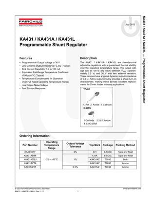
TO-92
8-SOIC
1. Ref 2. Anode 3. Cathode
1
1
1.Cathode 2.3.6.7.Anode
4.5.NC 8.Ref
- 2. KA431/KA431A/KA431L—ProgrammableShuntRegulator
© 2004 Fairchild Semiconductor Corporation www.fairchildsemi.com
KA431 / KA431A / KA431L Rev. 1.2.1 2
Block Diagram
Figure 1. Block Diagram
Absolute Maximum Ratings
Stresses exceeding the absolute maximum ratings may damage the device. The device may not function or be opera-
ble above the recommended operating conditions and stressing the parts to these levels is not recommended. In addi-
tion, extended exposure to stresses above the recommended operating conditions may affect device reliability. The
absolute maximum ratings are stress ratings only. Values are at TA = 25°C unless otherwise noted.
Recommended Operating Conditions
The Recommended Operating Conditions table defines the conditions for actual device operation. Recommended
operating conditions are specified to ensure optimal performance to the datasheet specifications. Fairchild does not
recommend exceeding them or designing to Absolute Maximum Ratings.
Symbol Parameter Value Unit
VKA Cathode Voltage 37 V
IKA Cathode Current Range (Continuous) -100 to +150 mA
IREF Reference Input Current Range -0.05 to +10 mA
PD
Power Dissipation
TO-92, 8-SOIC Packages
770 mW
RθjA
Thermal Resistance, Junction to Ambient
TO-92, 8-SOIC Packages
160 °C/W
TOPR Operating Temperature Range -25 to +85 °C
TJ Junction Temperature 150 °C
TSTG Storage Temperature Range -65 to +150 °C
Symbol Parameter Min. Max. Unit
VKA Cathode Voltage VREF 36 V
IKA Cathode Current 1 100 mA
2.5 Ref
CATHODE
ANODE
REFERENCE
ANODE(A)
REFERENCE (R)
CATHODE (K)
+
-
- 3. KA431/KA431A/KA431L—ProgrammableShuntRegulator
© 2004 Fairchild Semiconductor Corporation www.fairchildsemi.com
KA431 / KA431A / KA431L Rev. 1.2.1 3
Electrical Characteristics
Values are at TA = 25°C unless otherwise noted.
Note:
1. TMIN = -25°C, TMAX = +85°C.
Symbol Parameter Conditions
KA431 KA431A KA431L
Unit
Min. Typ. Max. Min. Typ. Max. Min. Typ. Max.
VREF
Reference
Input Voltage
VKA = VREF,
IKA = 10 mA
2.450 2.500 2.550 2.470 2.495 2.520 2.482 2.495 2.508 V
ΔVREF/
ΔT
Deviation of
Reference
Input Voltage
Over-
Temperature
VKA = VREF,
IKA =10 mA
TMIN ≤ TA ≤ TMAX
(1)
4.5 17.0 4.5 17.0 4.5 17.0 mV
ΔVREF/
ΔVKA
Ratio of
Change in
Reference
Input Voltage
to the
Change in
Cathode
Voltage
IKA =
10 mA
ΔVKA =
10V-VREF
-1.0 - 2.7 -1.0 - 2.7 -1.0 -2.7
mV / V
ΔVKA =
36 V-10 V
-0.5 -2.0 -0.5 -2.0 -0.5 -2.0
IREF
Reference
Input Current
IKA = 10 mA,
R1 =10 kΩ, R2 = ∞
1.5 4.0 1.5 4.0 1.5 4.0 μA
ΔIREF/ ΔT
Deviation of
Reference
Input Current
Over Full
Temperature
Range
IKA = 10 mA,
R1 = 10 kΩ, R2 = ∞
TA = Full Range
0.4 1.2 0.4 1.2 0.4 1.2
μA
IKA(MIN)
Minimum
Cathode
Current for
Regulation
VKA = VREF 0.45 1.00 0.45 1.00 0.45 1.00 mA
IKA(OFF)
Off - Stage
Cathode
Current
VKA = 36 V,
VREF = 0
0.05 1.00 0.05 1.00 0.05 1.00 μA
ZKA
Dynamic
Impedance
VKA = VREF,
IKA =1 to 100 mA
f ≥ 1.0 kHz
0.15 0.50 0.15 0.50 0.15 0.50 Ω
- 5. KA431/KA431A/KA431L—ProgrammableShuntRegulator
© 2004 Fairchild Semiconductor Corporation www.fairchildsemi.com
KA431 / KA431A / KA431L Rev. 1.2.1 5
Typical Performance Characteristics
Figure 5. Cathode Current vs. Cathode Voltage Figure 6. Cathode Current vs. Cathode Voltage
Figure 7. Change in Reference Input Voltage vs.
Cathode Voltage
Figure 8. Dynamic Impedance Frequency
Figure 9. Small Signal Voltage Amplification vs.
Frequency
Figure 10. Pulse Response
- 6. KA431/KA431A/KA431L—ProgrammableShuntRegulator
© 2004 Fairchild Semiconductor Corporation www.fairchildsemi.com
KA431 / KA431A / KA431L Rev. 1.2.1 6
Typical Performance Characteristics (Continued)
Figure11. Stability Boundary Conditions
100p 1n 10n 100n 1? 10?
0
20
40
60
80
100
120
140
D
C
B
A
A VKA
= Vref
B VKA
= 5.0 V @IK
= 10mA
C VKA
= 10 V @IK
= 10mA
D VKA
= 15 V @IK
= 10mA
TA
= 25
o
C
IK,CATHODECURRENT(mA)
CL
, LOAD CAPACITANCE
- 7. KA431/KA431A/KA431L—ProgrammableShuntRegulator
© 2004 Fairchild Semiconductor Corporation www.fairchildsemi.com
KA431 / KA431A / KA431L Rev. 1.2.1 7
Typical Application
Figure 12. Shunt Regulator Figure 13. Output Control for Three-
Terminal Fixed Regulator
Figure 14. High-Current Shunt
Regulator
Figure 15. Current Limit or Current Source Figure 16. Constant-Current Sink
VO 1
R1
R2
-------+
V
ref
= VO Vref 1
R
1
R
2
-------+
= VO 1
R1
R2
-------+
V
ref
=
- 8. KA431/KA431A/KA431L—ProgrammableShuntRegulator
© 2004 Fairchild Semiconductor Corporation www.fairchildsemi.com
KA431 / KA431A / KA431L Rev. 1.2.1 8
Physical Dimensions
Figure 17. 3-Lead, TO-92, Molded, Standard Straight Lead
Package drawings are provided as a service to customers considering Fairchild components. Drawings may change in any manner
without notice. Please note the revision and/or date on the drawing and contact a Fairchild Semiconductor representative to verify or
obtain the most recent revision. Package specifications do not expand the terms of Fairchild’s worldwide terms and conditions, specifically the
warranty therein, which covers Fairchild products.
Always visit Fairchild Semiconductor’s online packaging area for the most recent package drawings:
http://www.fairchildsemi.com/dwg/ZA/ZA03D.pdf.
For current tape and reel specifications, visit Fairchild Semiconductor’s online packaging area:
http://www.fairchildsemi.com/packing_dwg/PKG-ZA03D_BK.pdf.
D
TO-92 Bulk Type
D) DRAWING FILENAME: MKT-ZA03DREV3.
- 9. KA431/KA431A/KA431L—ProgrammableShuntRegulator
© 2004 Fairchild Semiconductor Corporation www.fairchildsemi.com
KA431 / KA431A / KA431L Rev. 1.2.1 9
Physical Dimensions (Continued)
Figure 18. 3-Lead, TO-92, Molded, 0.200 in Line Spacing Lead Form
Package drawings are provided as a service to customers considering Fairchild components. Drawings may change in any manner
without notice. Please note the revision and/or date on the drawing and contact a Fairchild Semiconductor representative to verify or
obtain the most recent revision. Package specifications do not expand the terms of Fairchild’s worldwide terms and conditions, specifically the
warranty therein, which covers Fairchild products.
Always visit Fairchild Semiconductor’s online packaging area for the most recent package drawings:
http://www.fairchildsemi.com/dwg/ZA/ZA03F.pdf.
For current tape and reel specifications, visit Fairchild Semiconductor’s online packaging area:
http://www.fairchildsemi.com/packing_dwg/PKG-ZA03F_BK.pdf.
D
TO-92 Ammo Type
D) DRAWING FILENAME: MKT-ZA03FREV2.
- 10. KA431/KA431A/KA431L—ProgrammableShuntRegulator
© 2004 Fairchild Semiconductor Corporation www.fairchildsemi.com
KA431 / KA431A / KA431L Rev. 1.2.1 10
Physical Dimensions (Continued)
Figure 19. 8-Lead, SOIC, JEDEC MS 0-12, 0.150 inch Narrow Body
Package drawings are provided as a service to customers considering Fairchild components. Drawings may change in any manner
without notice. Please note the revision and/or date on the drawing and contact a Fairchild Semiconductor representative to verify or
obtain the most recent revision. Package specifications do not expand the terms of Fairchild’s worldwide terms and conditions, specifically the
warranty therein, which covers Fairchild products.
Always visit Fairchild Semiconductor’s online packaging area for the most recent package drawings:
http://www.fairchildsemi.com/dwg/M0/M08A.pdf.
For current tape and reel specifications, visit Fairchild Semiconductor’s online packaging area:
http://www.fairchildsemi.com/packing_dwg/PKG-M08A_PSTS.pdf.
8°
0°
SEE DETAIL A
NOTES: UNLESS OTHERWISE SPECIFIED
A) THIS PACKAGE CONFORMS TO JEDEC
MS-012, VARIATION AA.
B) ALL DIMENSIONS ARE IN MILLIMETERS.
C) DIMENSIONS DO NOT INCLUDE MOLD
FLASH OR BURRS.
D) LANDPATTERN STANDARD: SOIC127P600X175-8M.
E) DRAWING FILENAME: M08Arev14
F) FAIRCHILD SEMICONDUCTOR.
LAND PATTERN RECOMMENDATION
SEATING PLANE
C
GAGE PLANE
x 45°
DETAIL A
SCALE: 2:1
PIN ONE
INDICATOR
4
8
1
B
5
A
5.60
0.65
1.75
1.27
6.20
5.80
3.81
4.00
3.80
5.00
4.80
(0.33)
1.27
0.51
0.33
0.25
0.10
1.75 MAX
0.25
0.19
0.36
0.50
0.25
R0.10
R0.10
0.90
0.40
(1.04)
OPTION A - BEVEL EDGE
OPTION B - NO BEVEL EDGE
0.25 C B A
0.10
8-SOIC
- 11. © Fairchild Semiconductor Corporation www.fairchildsemi.com
TRADEMARKS
The following includes registered and unregistered trademarks and service marks, owned by Fairchild Semiconductor and/or its global subsidiaries, and is not
intended to be an exhaustive list of all such trademarks.
2Cool
AccuPower
AX-CAP®
*
BitSiC
Build it Now
CorePLUS
CorePOWER
CROSSVOLT
CTL
Current Transfer Logic
DEUXPEED®
Dual Cool™
EcoSPARK®
EfficientMax
ESBC
Fairchild®
Fairchild Semiconductor®
FACT Quiet Series
FACT®
FAST®
FastvCore
FETBench
FPS
F-PFS
FRFET®
Global Power Resource
SM
GreenBridge
Green FPS
Green FPS e-Series
Gmax
GTO
IntelliMAX
ISOPLANAR
Making Small Speakers Sound Louder
and Better™
MegaBuck
MICROCOUPLER
MicroFET
MicroPak
MicroPak2
MillerDrive
MotionMax
mWSaver
OptoHiT
OPTOLOGIC®
OPTOPLANAR®
®
PowerTrench®
PowerXS™
Programmable Active Droop
QFET®
QS
Quiet Series
RapidConfigure
Saving our world, 1mW/W/kW at a time™
SignalWise
SmartMax
SMART START
Solutions for Your Success
SPM®
STEALTH
SuperFET®
SuperSOT -3
SuperSOT -6
SuperSOT -8
SupreMOS®
SyncFET
Sync-Lock™
®*
TinyBoost
TinyBuck
TinyCalc
TinyLogic®
TINYOPTO
TinyPower
TinyPWM
TinyWire
TranSiC
TriFault Detect
TRUECURRENT®
*
SerDes
UHC®
Ultra FRFET
UniFET
VCX
VisualMax
VoltagePlus
XS™
* Trademarks of System General Corporation, used under license by Fairchild Semiconductor.
DISCLAIMER
FAIRCHILD SEMICONDUCTOR RESERVES THE RIGHT TO MAKE CHANGES WITHOUT FURTHER NOTICE TO ANY PRODUCTS HEREIN TO IMPROVE
RELIABILITY, FUNCTION, OR DESIGN. FAIRCHILD DOES NOT ASSUME ANY LIABILITY ARISING OUT OF THE APPLICATION OR USE OF ANY PRODUCT
OR CIRCUIT DESCRIBED HEREIN; NEITHER DOES IT CONVEY ANY LICENSE UNDER ITS PATENT RIGHTS, NOR THE RIGHTS OF OTHERS. THESE
SPECIFICATIONS DO NOT EXPAND THE TERMS OF FAIRCHILD’S WORLDWIDE TERMS AND CONDITIONS, SPECIFICALLY THE WARRANTY THEREIN,
WHICH COVERS THESE PRODUCTS.
LIFE SUPPORT POLICY
FAIRCHILD’S PRODUCTS ARE NOT AUTHORIZED FOR USE AS CRITICAL COMPONENTS IN LIFE SUPPORT DEVICES OR SYSTEMS WITHOUT THE
EXPRESS WRITTEN APPROVAL OF FAIRCHILD SEMICONDUCTOR CORPORATION.
As used herein:
1. Life support devices or systems are devices or systems which, (a) are
intended for surgical implant into the body or (b) support or sustain
life, and (c) whose failure to perform when properly used in
accordance with instructions for use provided in the labeling, can be
reasonably expected to result in a significant injury of the user.
2. A critical component in any component of a life support, device, or
system whose failure to perform can be reasonably expected to
cause the failure of the life support device or system, or to affect its
safety or effectiveness.
ANTI-COUNTERFEITING POLICY
Fairchild Semiconductor Corporation's Anti-Counterfeiting Policy. Fairchild's Anti-Counterfeiting Policy is also stated on our external website, www.fairchildsemi.com,
under Sales Support.
Counterfeiting of semiconductor parts is a growing problem in the industry. All manufacturers of semiconductor products are experiencing counterfeiting of their
parts. Customers who inadvertently purchase counterfeit parts experience many problems such as loss of brand reputation, substandard performance, failed
applications, and increased cost of production and manufacturing delays. Fairchild is taking strong measures to protect ourselves and our customers from the
proliferation of counterfeit parts. Fairchild strongly encourages customers to purchase Fairchild parts either directly from Fairchild or from Authorized Fairchild
Distributors who are listed by country on our web page cited above. Products customers buy either from Fairchild directly or from Authorized Fairchild Distributors
are genuine parts, have full traceability, meet Fairchild's quality standards for handling and storage and provide access to Fairchild's full range of up-to-date technical
and product information. Fairchild and our Authorized Distributors will stand behind all warranties and will appropriately address any warranty issues that may arise.
Fairchild will not provide any warranty coverage or other assistance for parts bought from Unauthorized Sources. Fairchild is committed to combat this global
problem and encourage our customers to do their part in stopping this practice by buying direct or from authorized distributors.
PRODUCT STATUS DEFINITIONS
Definition of Terms
Datasheet Identification Product Status Definition
Advance Information Formative / In Design
Datasheet contains the design specifications for product development. Specifications may change
in any manner without notice.
Preliminary First Production
Datasheet contains preliminary data; supplementary data will be published at a later date. Fairchild
Semiconductor reserves the right to make changes at any time without notice to improve design.
No Identification Needed Full Production
Datasheet contains final specifications. Fairchild Semiconductor reserves the right to make
changes at any time without notice to improve the design.
Obsolete Not In Production
Datasheet contains specifications on a product that is discontinued by Fairchild Semiconductor.
The datasheet is for reference information only.
Rev. I64
®