
Recommended
More Related Content
Similar to faults and joints, Geophysical methods.pptx
Similar to faults and joints, Geophysical methods.pptx (20)
More from pandieswarim1
Recently uploaded
Recently uploaded (20)
faults and joints, Geophysical methods.pptx
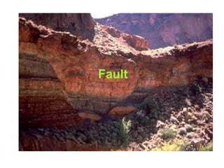
- 1. Fault
- 2. 2 Forces that cause deformation Ductile Brittle Convergent Divergent Transform
- 3. • Fracturing is favoured when the stresses are shearing in nature and the rocks are brittle in character. • Fractures along which there has been relative movement of the blocks past each other are termed as faults. • The entire process of development of fractures and displacement of the blocks against each other is termed as faulting.
- 4. – Footwall (rock mass below the fault) Hanging wall (rock mass above the fault) Fault blocks classified as
- 5. • Dip-slip faults – Motion is parallel to fault dip. • Strike-slip faults – Motion is parallel to fault strike. Fault Types
- 6. • Two dominant types – Normal fault – Reverse Fault • Thrust (a low angle reverse fault) Types of Dip-Slip Faults
- 7. NORMAL FAULT - a fault along which the hanging wall has moved relatively downward - caused by tensional stress-stress that acts to pull the crust apart. - causes overall extension of the crust.
- 8. REVERSE FAULT A Reverse Faults: is a thrust fault that dips more than 45 . Reverse faulting is a response to compression. Reverse faulting shortens the horizontal extent of the crust.
- 9. • Strike-slip fault • Transform fault – Large strike-slip fault that cuts through the lithosphere – Accommodates motion between two large crustal plates Strike-Slip Faults
- 10. NORMAL FAULT
- 13. ATTITUDE OF FAULTS The Strike of fault is the trend of a horizontal line in the plane of the fault. The Dip is the angle between a horizontal surface and the plane of the fault; It is measured in a vertical plane that strikes at right angles to the fault.
- 14. Joints In geology the term joint refers to a fracture in rock where the displacement associated with the opening of the fracture is greater than the displacement due to lateral movement in the plane of the fracture (up, down or sideways) of one side relative to the other
- 15. Columnar joints
- 17. Columnar joints
- 20. GEOPHYSICAL METHODS GEOLOGICAL SITE INVESTIGATIONS •Artificially introduced FORCES INTO GEOLOGIC FORMATIONS. •Used in assessing •Ground conditions •Materials •Groundwater
- 21. ELECTRICAL RESISTIVITY METHODS •ELECTRICAL SOUNDING – WENNER (1915) •PRINCIPLE: based on the principle that electrical resistivity of loose unconsolidated or partially consolidated surface materials like the products of rock weathering and erosion such as soil loess, alluvium, sand and clay is different from that of bedrock over which they are deposited. •Electrical resistivity – shows difference •Loose unconsolidated or partially consolidated surface materials (rock weathering and erosion) •Lower electrical resistance –in more porous or jointed and fissured the rock. •Igneous and metamorphic rock in general – greater resistance than the sedimentary rocks.
- 23. In resistivity soundings, the distance between the current electrodes or the distance between the current and potential dipoles is expanded in a regular manner between readings, thus yielding information of the electrical properties of soils from deeper and deeper depths. Electrode arrangement
- 24. In resistivity profiling, the electrode spacing is fixed, and measurements are taken at successive intervals along a profile. Data are generally presented as profiles or contour maps and interpreted qualitatively.
- 25. •EQUIPMENTS •A generator or a high voltage battery (200 v) – source of current •A measuring assembly •A voltmeter •A potentiometer - for measuring small potential differences accurately •A multi-range milli-ammeter – for measuring currents •Four stainless steel, copper, or other metallic spikes (electrodes). • 800 m long and 20 mm diameter •heads for easy driving into ground •clamps for cable connection •stranded insulated single conductor cable •0.5 m conducting area •cable parable needs •devices for eliminating effects of polarization of electrode and small currents in the ground •spares.
- 26. P=resistivity in ohm V=potential difference i=current in amperes d=1/3 ,a,, where a =total distance between outer electrodes
- 28. SEISMIC METHODS •PRINCIPLE •Seismic (elastic) waves travel through subsurface materials (soil and rock) at difference velocities. •Their propagation – influenced by certain combinations of density, modulus of elasticity and poisson;s ratio of geologic bodies. •Suffer – absorption, reflection and refraction - comparable to optical phenomena. Measuring the time taken by the seismic waves set up by an explosion at the surface to travel directly or after suffering reflection and refraction at subsurface discontinuities and determine the depth of bedrock
- 30. •REFRACTION METHOD •Determining the distance between the Earth’s surface and one or more reflecting surface i.e. depth to bedrock (HRL) and or thickness underground on the basis of the travel – time of seismic waves. •EQUIPMENT :- shallow refraction seismic equipments. •Geophones (seismometer) three to twelve vibration detectors •A battery operated amplifier unit with several independent amplifiers for each geophone detector. •A multichannel oscillograph •An exploder •Charge ( dynamite) •Insulated cable •A portable processing facilities •Spares.
- 31. •FIELD PROCEDURE AND INTERPRETATION •A hole – shot hole – 1.5 – 2mts kg – dynamite •Geophones – straight line – profile – shooting •Round shot hole – arc-shooting / fan – shooting •SEISMIC SPREAD – the area over which the exploration is made from a given shot point is called seismic spread. •Plotting the first arrival times and distances i.e. the time elapsed between the explosion and reception of the waves by variations. •Travel distance graph – hodograph •D = x/2 v2-v1 / v2 = v1 where v1 = velocity of seismic waves in overburden •V2 = velocity of seismic waves in bed rock •X = critical distance •D = depth to bedrock.
- 32. •FIELD PROCEDURE AND INTERPRETATION •A hole – shot hole – 1.5 – 2mts kg – dynamite •Geophones – straight line – profile – shooting •Round shot hole – arc-shooting / fan – shooting •SEISMIC SPREAD – the area over which the exploration is made from a given shot point is called seismic spread. •Plotting the first arrival times and distances i.e. the time elapsed between the explosion and reception of the waves by variations. •Travel distance graph – hodograph •D = x/2 v2-v1 / v2 = v1 where v1 = velocity of seismic waves in overburden •V2 = velocity of seismic waves in bed rock •X = critical distance •D = depth to bedrock.
- 33. •FIELD PROCEDURE AND INTERPRETATION •A hole – shot hole – 1.5 – 2mts kg – dynamite •Geophones – straight line – profile – shooting •Round shot hole – arc-shooting / fan – shooting •SEISMIC SPREAD – the area over which the exploration is made from a given shot point is called seismic spread. •Plotting the first arrival times and distances i.e. the time elapsed between the explosion and reception of the waves by variations. •Travel distance graph – hodograph •D = x/2 v2-v1 / v2 = v1 where v1 = velocity of seismic waves in overburden •V2 = velocity of seismic waves in bed rock •X = critical distance •D = depth to bedrock.