
Recommended
Recommended
More Related Content
Similar to Caterpillar Cat D7F TRACK-TYPE TRACTOR (Prefix 94N) Service Repair Manual Instant Download.pdf
Similar to Caterpillar Cat D7F TRACK-TYPE TRACTOR (Prefix 94N) Service Repair Manual Instant Download.pdf (20)
More from onyvzcwadtu05
More from onyvzcwadtu05 (20)
Recently uploaded
Recently uploaded (20)
Caterpillar Cat D7F TRACK-TYPE TRACTOR (Prefix 94N) Service Repair Manual Instant Download.pdf
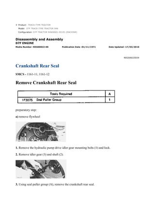
- 1. Product: TRACK-TYPE TRACTOR Model: D7F TRACK-TYPE TRACTOR 94N Configuration: D7F TRACTOR 94N00001-05191 (MACHINE) Disassembly and Assembly D7F ENGINE Media Number -REG00822-00 Publication Date -01/11/1971 Date Updated -17/03/2010 REG008220034 Crankshaft Rear Seal SMCS - 1161-11; 1161-12 Remove Crankshaft Rear Seal preparatory step: a) remove flywheel 1. Remove the hydraulic pump drive idler gear mounting bolts (1) and lock. 2. Remove idler gear (3) and shaft (2). 3. Using seal puller group (A), remove the crankshaft rear seal. 1/3 D7F TRACTOR 94N00001-05191 (MACHINE)(UEG0234S - 00) - Documentation 2021/8/13 https://127.0.0.1/sisweb/sisweb/techdoc/techdoc_print_page.jsp?returnurl=/sis...
- 2. Install Crankshaft Rear Seal 1. Using tool setup (A), install the crankshaft rear seal as follows: TYPICAL EXAMPLE a) Install the locator assembly (3) and retaining screws (2) on the crankshaft. b) Lubricate the lip of seal and the seal pilot (1) with clean SAE 30 engine oil. Place the seal on the seal pilot (1) with thickest portion of seal outer metal shell toward the flywheel. Coat the seal 2/3 D7F TRACTOR 94N00001-05191 (MACHINE)(UEG0234S - 00) - Documentation 2021/8/13 https://127.0.0.1/sisweb/sisweb/techdoc/techdoc_print_page.jsp?returnurl=/sis...
- 3. outer metal shell with 8M8059 Loctite Sealant. Slide the seal pilot (1) onto the locator assembly (3) and the crankshaft. c) Place the seal installer ring (6) on the pusher plate (5), and slide the pusher plate onto the stud of the locator assembly (3). d) Lubricate the nut (4) with clean SAE 30 engine oil, and install nut on stud of locator assembly (3). e) Tighten the nut (4) until the seal bottoms. 2. Remove tool setup (A). 3. Install the idler gear (7) and shaft (8). Install retaining bolts and lock. concluding step: a) install flywheel 3/3 D7F TRACTOR 94N00001-05191 (MACHINE)(UEG0234S - 00) - Documentation 2021/8/13 https://127.0.0.1/sisweb/sisweb/techdoc/techdoc_print_page.jsp?returnurl=/sis...
- 4. Product: TRACK-TYPE TRACTOR Model: D7F TRACK-TYPE TRACTOR 94N Configuration: D7F TRACTOR 94N00001-05191 (MACHINE) Disassembly and Assembly D7F ENGINE Media Number -REG00822-00 Publication Date -01/11/1971 Date Updated -17/03/2010 REG008220035 Power Take-Off Drive Gears & Bearings SMCS - 1165-11; 1165-12 Remove Power Take-Off Drive Gears And Bearings preparatory step: a) remove transmission oil pump 1. Remove the front right floor plate and the access plate. Remove the cover assembly (1). 2. Remove the covers (2) and (3) from the cover assembly. Using tool setup (A), remove the bearings from the cover assembly. Remove the thrust washers from the cover assembly. 1/3 D7F TRACTOR 94N00001-05191 (MACHINE)(UEG0234S - 00) - Documentation 2021/8/13 https://127.0.0.1/sisweb/sisweb/techdoc/techdoc_print_page.jsp?returnurl=/sis...
- 5. 3. Remove the two drive gears. Remove the cover on front side of flywheel housing. Using tool setup (A), remove the bearings from flywheel housing. Remove the thrust washers (4) from housing. NOTE: If idler gear (5) and drive gear on crankshaft are to be removed, it will be necessary to remove the flywheel. See REMOVE FLYWHEEL. Install Power Take-Off Drive Gears And Bearings 1. Using tool setup (A), install the bearings in flywheel housing with hole in bearing aligned with hole in flywheel housing. Install the thrust washers in housing. 2. Using tool setup (A), install bearings in the cover assembly with hole in bearing aligned with hole in cover assembly. Install thrust washers in cover assembly. Install the two covers on the cover assembly. 2/3 D7F TRACTOR 94N00001-05191 (MACHINE)(UEG0234S - 00) - Documentation 2021/8/13 https://127.0.0.1/sisweb/sisweb/techdoc/techdoc_print_page.jsp?returnurl=/sis...
- 6. 3. Throughly lubricate all bearings and thrust washers with clean SAE 30 engine oil. 4. Install the two drive gears in flywheel housing. Install the front cover on flywheel housing. 5. Install the cover assembly on flywheel housing. concluding step: a) install transmission oil pump 3/3 D7F TRACTOR 94N00001-05191 (MACHINE)(UEG0234S - 00) - Documentation 2021/8/13 https://127.0.0.1/sisweb/sisweb/techdoc/techdoc_print_page.jsp?returnurl=/sis...
- 7. Product: TRACK-TYPE TRACTOR Model: D7F TRACK-TYPE TRACTOR 94N Configuration: D7F TRACTOR 94N00001-05191 (MACHINE) Disassembly and Assembly D7F ENGINE Media Number -REG00822-00 Publication Date -01/11/1971 Date Updated -17/03/2010 REG008220036 Engine SMCS - 1000-11; 1000-12 Remove Engine preparatory step: a) remove hood 1. Drain the engine cooling system - capacity 12 U.S. Gal. (45 liters). 2. Drain the oil from the flywheel housing. 3. Remove the cover plates from bottom of fuel tank, and shut off the fuel supply line. 4. Disconnect the water pressure gauge sensing line (1) from the radiator top tank. 5. Disconnect radiator water outlet line hose from the water pump. Disconnect hose (2) from radiator water inlet elbow. 1/7 D7F TRACTOR 94N00001-05191 (MACHINE)(UEG0234S - 00) - Documentation 2021/8/13 https://127.0.0.1/sisweb/sisweb/techdoc/techdoc_print_page.jsp?returnurl=/sis...
- 8. 6. Remove the fan adapter mounting bolts (3), and lay the fan and adapter inside the radiator guard. 7. Remove the fan belts (4). Remove the fan drive assembly (5). 8. Disconnect the fuel supply line (6) from the accessory drive housing. 9. Disconnect starter ground cable (7) from the starter. 10. Disconnect the positive cable (8) from the starter, and pull the cable through to the left side of tractor. 11. Remove the floor plates. 12. Disconnect the transmission oil cooler oil inlet line (9) at both ends. 13. Disconnect the power take-off drive gears lubrication line (10) from oil inlet line (9). 14. Remove the oil inlet line clamp mounting bolt (11), and rotate the oil inlet line (9) upward. 15. Disconnect the oil cooler oil outlet line (12) from the oil cooler. 16. Disconnect the steering clutch control rods at both ends, and slide the rods toward the rear of tractor. 2/7 D7F TRACTOR 94N00001-05191 (MACHINE)(UEG0234S - 00) - Documentation 2021/8/13 https://127.0.0.1/sisweb/sisweb/techdoc/techdoc_print_page.jsp?returnurl=/sis...
- 9. 17. On the direct drive tractor only: a) Remove transmission vent line (13). b) Remove the drive shaft (14). c) Disconnect the scavenge pump oil outlet line (15) from pump. d) Disconnect hose (16) from transmission oil pump oil outlet line (17). e) Loosen hose clamp, and remove the magnetic strainer oil inlet line (18). f) Remove the flywheel clutch control lever (19). NOTE: The brake pedal assembly has been removed for illustrative purposes only. 18. On the power shift tractor only: a) Remove the transmission vent line (20). b) Remove the drive shaft (21). c) Disconnect oil temperature sensing line (22) from the torque divider. d) Remove the transmission oil pump oil outlet line (23). e) Disconnect the oil outlet line (24) from the scavenge pump. f) Disconnect the torque divider oil supply line (25) from the torque divider. NOTE: The brake pedal assembly has been removed for illustrative purposes only. 3/7 D7F TRACTOR 94N00001-05191 (MACHINE)(UEG0234S - 00) - Documentation 2021/8/13 https://127.0.0.1/sisweb/sisweb/techdoc/techdoc_print_page.jsp?returnurl=/sis...
- 10. 19. Remove the two engine front support-to-frame mounting bolts (26). 20. Remove the four engine rear support-to-frame mounting bolts (27). Remove the two dash support brace mounting bolts (28). 21. Attach a hoist and remove the engine - weight 2700 lbs. (1225 kg). Install Engine 1. Attach a hoist and position the engine in tractor. 2. Install the four engine rear support-to-frame mounting bolts (1) and the two dash support brace mounting bolts (2). Install the two engine front support-to-frame mounting bolts. 4/7 D7F TRACTOR 94N00001-05191 (MACHINE)(UEG0234S - 00) - Documentation 2021/8/13 https://127.0.0.1/sisweb/sisweb/techdoc/techdoc_print_page.jsp?returnurl=/sis...
- 11. 3. On the power shift tractor only: a) Connect the torque divider oil supply line (3) to the torque divider. b) Connect the oil outlet line (4) to the scavenge pump. c) Install the transmission oil pump oil outlet line (5). d) Connect oil temperature sensing line (6) to the torque divider. e) Install the drive shaft (7). Install and tighten retaining bolts to 100 ± 10 lb. ft. (13,8 ± 1,4 mkg). f) Install the transmission vent line (8). 4. On direct drive tractor only: a) Install the flywheel clutch control lever (9). b) Install magnetic strainer oil inlet line (10), and tighten hose clamp. c) Connect hose (11) to transmission oil pump oil outlet line (12). d) Connect the scavenge pump oil outlet line (13) to the pump. e) Install the drive shaft (14). Install and tighten retaining bolts to 100 ± 10 lb. ft. (13,8 ± 1,4 mkg). f) Install transmission vent line (15). 5. Install the steering clutch control rods. 5/7 D7F TRACTOR 94N00001-05191 (MACHINE)(UEG0234S - 00) - Documentation 2021/8/13 https://127.0.0.1/sisweb/sisweb/techdoc/techdoc_print_page.jsp?returnurl=/sis...
- 12. 6. Connect the oil cooler oil outlet line (17) to the oil cooler. 7. Position the oil inlet line (18), and connect the line at both ends. 8. Install the oil inlet line clamp mounting bolt (19). 9. Connect the power take-off drive gears lubrication line (20) to oil inlet line (18). 10. Install the floor plates. 11. Pull the positive battery cable (21) through to the right side of tractor, and connect cable to starter. 12. Connect the ground cable (22) to the starter. 13. Connect the fuel supply line (23) to the accessory drive housing. 14. Install the fan drive assembly (24). Install and adjust the fan belts (25). 15. Position the fan and adapter on the fan drive assembly, and install fan adapter mounting bolts (26). 6/7 D7F TRACTOR 94N00001-05191 (MACHINE)(UEG0234S - 00) - Documentation 2021/8/13 https://127.0.0.1/sisweb/sisweb/techdoc/techdoc_print_page.jsp?returnurl=/sis...
- 13. 16. Connect hose (27) to radiator water inlet elbow. 17. Connect radiator water outlet line hose to the water pump. 18. Connect water pressure gauge sensing line (28) to the radiator top tank. 19. Turn the fuel supply line on at the tank. 20. Install the fuel tank bottom cover plates. 21. Fill the engine cooling system. 22. Start the engine. Check the oil level in the transmission, and fill as necessary. concluding step: a) install hood 7/7 D7F TRACTOR 94N00001-05191 (MACHINE)(UEG0234S - 00) - Documentation 2021/8/13 https://127.0.0.1/sisweb/sisweb/techdoc/techdoc_print_page.jsp?returnurl=/sis...
- 14. Product: TRACK-TYPE TRACTOR Model: D7F TRACK-TYPE TRACTOR 94N Configuration: D7F TRACTOR 94N00001-05191 (MACHINE) Disassembly and Assembly D7F ENGINE Media Number -REG00822-00 Publication Date -01/11/1971 Date Updated -17/03/2010 REG008220037 Flywheel Housing SMCS - 1157-11; 1157-12 Remove Flywheel Housing preparatory steps: a) remove engine b) remove torque divider (power shift machine) or remove flywheel clutch (direct drive machine) c) remove flywheel d) remove oil pan plate e) remove transmission oil pump 1. Remove the starter. 2. Remove the hydraulic pump drive idler gear retaining bolts (1) and lock. Remove the idler gear (3) and shaft (2). 3. Attach a hoist to the flywheel housing, and remove the flywheel housing mounting bolts (4). Remove the flywheel housing - weight 350 lbs. (160 kg). 1/2 D7F TRACTOR 94N00001-05191 (MACHINE)(UEG0234S - 00) - Documentation 2021/8/13 https://127.0.0.1/sisweb/sisweb/techdoc/techdoc_print_page.jsp?returnurl=/sis...
- 15. Install Flywheel Housing 1. Remove the old flywheel housing-to-cylinder block gasket. Install a new gasket. 2. Attach a hoist and position the flywheel housing on the engine. Install the flywheel housing mounting bolts. 3. Trim the flywheel housing-to-cylinder block gasket flush with oil pan face of cylinder block. 4. Position the hydraulic pump drive idler gear and shaft in the flywheel housing, and install mounting bolts and lock. 5. Install the starter. concluding steps: a) install transmission oil pump b) install oil pan plate c) install flywheel d) install torque divider (power shift machine) or install flywheel clutch (direct drive machine) e) install engine 2/2 D7F TRACTOR 94N00001-05191 (MACHINE)(UEG0234S - 00) - Documentation 2021/8/13 https://127.0.0.1/sisweb/sisweb/techdoc/techdoc_print_page.jsp?returnurl=/sis...
- 16. Product: TRACK-TYPE TRACTOR Model: D7F TRACK-TYPE TRACTOR 94N Configuration: D7F TRACTOR 94N00001-05191 (MACHINE) Disassembly and Assembly D7F ENGINE Media Number -REG00822-00 Publication Date -01/11/1971 Date Updated -17/03/2010 REG008220038 Camshaft Bearings SMCS - 1211-11; 1211-12 Remove Camshaft Bearings preparatory steps: a) remove engine b) remove flywheel housing c) remove pistons d) remove camshaft 1. Using tool group (A), remove the camshaft bearings starting with the front bearing. Install Camshaft Bearings 1/2 D7F TRACTOR 94N00001-05191 (MACHINE)(UEG0234S - 00) - Documentation 2021/8/13 https://127.0.0.1/sisweb/sisweb/techdoc/techdoc_print_page.jsp?returnurl=/sis...
- 17. 1. Using tool group (A), install the camshaft bearings in the cylinder block starting with the front bearings. Install all bearings with oil hole in bearing aligned with oil hole in cylinder block. 2. At installation, the front and rear bearings are to be recessed .06 in. (1,5 mm) from their respective ends of the cylinder block. concluding steps: a) install camshaft b) install pistons c) install flywheel housing d) install engine 2/2 D7F TRACTOR 94N00001-05191 (MACHINE)(UEG0234S - 00) - Documentation 2021/8/13 https://127.0.0.1/sisweb/sisweb/techdoc/techdoc_print_page.jsp?returnurl=/sis...
- 18. Product: TRACK-TYPE TRACTOR Model: D7F TRACK-TYPE TRACTOR 94N Configuration: D7F TRACTOR 94N00001-05191 (MACHINE) Disassembly and Assembly D7F ENGINE Media Number -REG00822-00 Publication Date -01/11/1971 Date Updated -17/03/2010 REG008220039 Crankshaft SMCS - 1202-11; 1202-12 Remove Crankshaft preparatory steps: a) remove engine b) remove flywheel housing c) remove timing gear cover d) remove pistons 1. Rotate the crankshaft until the "C" mark on the crankshaft gear (1) is aligned with the "C" mark on the camshaft gear (2). 2. Mark the mating teeth of the accessory drive shaft gear and idler gear at location (A). Mark the mating teeth of idler gear and camshaft gear at location (B). This will insure proper fuel injection pump camshaft timing during installation of the crankshaft. 1/4 D7F TRACTOR 94N00001-05191 (MACHINE)(UEG0234S - 00) - Documentation 2021/8/13 https://127.0.0.1/sisweb/sisweb/techdoc/techdoc_print_page.jsp?returnurl=/sis...
- 19. 3. Attach a hoist to the crankshaft. 4. Remove the crankshaft main bearing caps. 5. Remove the crankshaft - weight 200 lbs. (91 kg). 6. Remove the crankshaft main bearings from the cylinder block and from main bearing caps. Install Crankshaft 1. Clean the bearing seating surfaces in the cylinder block. Install the upper halves of main bearings in the block. Lubricate the bearings with clean SAE 30 engine oil. 2. Attach a hoist and position the crankshaft in cylinder block with all timing marks aligned. 3. Clean the bearing seating surfaces of the main bearing caps. Install lower halves of main bearings in the caps. 4. Using wire (A), check the main bearing clearance. Install the caps in their respective positions with the number stamped on cap facing the corresponding number stamped on pan face on left side of cylinder block. 5. Lubricate the threads of bearing cap retaining bolts and face of washers with clean SAE 30 engine oil. Install the retaining bolts and washers. Tighten both bolts to 30 ± 3 lb. ft. (4,1 ± 0,4 mkg). Mark both bolt heads and bearing caps then tighten each bolt an additional 90° from mark. 2/4 D7F TRACTOR 94N00001-05191 (MACHINE)(UEG0234S - 00) - Documentation 2021/8/13 https://127.0.0.1/sisweb/sisweb/techdoc/techdoc_print_page.jsp?returnurl=/sis...
- 20. Remove bearing caps and measure thickness of wire (A). Main bearing clearance should be .0030- .0059 in. (0,076-0,150 mm). 6. Lubricate the lower halves of main bearings with clean SAE 30 engine oil. Install the main bearing caps in their respective positions. Install cap retaining bolts and washers. Tighten both bolts to 30 ± 3 lb. ft. (4,1 ± 0,4 mkg). Mark both bolt heads and bearing caps then tighten each bolt an additional 90° from mark. 7. Using tool setup (B), check the crankshaft end play as controlled by thrust bearings (1) on rear main bearing. End play should be .0025 - .0145 in. (0,064, - 0,368 mm). Maximum permissible end play is .025 in. (0,64 mm). 8. If the accessory drive shaft gear, idler gear, or camshaft gear has been removed or if the crankshaft gear has been replaced, it will be necessary to time the accessory drive shaft after assembling the engine. See REMOVE AND INSTALL FUEL INJECTION PUMP HOUSING AND GOVERNOR AS A UNIT. concluding steps: a) install pistons b) install timing gear cover c) install flywheel housing d) install engine 3/4 D7F TRACTOR 94N00001-05191 (MACHINE)(UEG0234S - 00) - Documentation 2021/8/13 https://127.0.0.1/sisweb/sisweb/techdoc/techdoc_print_page.jsp?returnurl=/sis...
- 21. Product: TRACK-TYPE TRACTOR Model: D7F TRACK-TYPE TRACTOR 94N Configuration: D7F TRACTOR 94N00001-05191 (MACHINE) Disassembly and Assembly D7F TRACTOR POWER TRAIN Media Number -REG00823-00 Publication Date -01/11/1971 Date Updated -24/02/2016 REG008230001 Sprocket Segments SMCS - 4165-10; 4180-11 Remove And Install Sprocket Segments 1. Remove the sprocket guards. 2. Move the machine forward or backward to position segment to be removed. 3. Remove the retaining bolts and nuts, and remove sprocket segment. 4. Lubricate the threads of retaining bolts with high pressure lubricant. Position the segment on hub, and install retaining bolts with head of bolts against hub. Install retaining nuts and tighten all nuts to 220 ± 40 lb. ft. (30,4 ± 5,5 mkg). Then, retighten each nut an additional 1/3 turn. 5. Repeat Step 2 through Step 4 for the remaining segments. 6. Install sprocket guards. Remove Track Rollers 1/3 D7F TRACTOR 94N00001-05191 (MACHINE)(UEG0234S - 00) - Documentation 2021/8/13 https://127.0.0.1/sisweb/sisweb/techdoc/techdoc_print_page.jsp?returnurl=/sis...
- 22. 1. Start the tractor, and drive it up on lift assemblies (A). Position stands (B) under tractor. 2. Adjust the track until it is tight against the track rollers. NOTICE Do not tighten track too tight. Damage to the track adjusting seals will result if overtightened. 3. Remove the four track roller mounting bolts. 4. Open the track adjusting relief valve. Lower the track until track roller clears frame. 5. Remove the track roller - weight 215 lbs. (98 kg). 2/3 D7F TRACTOR 94N00001-05191 (MACHINE)(UEG0234S - 00) - Documentation 2021/8/13 https://127.0.0.1/sisweb/sisweb/techdoc/techdoc_print_page.jsp?returnurl=/sis...
- 23. Suggest: If the above button click is invalid. Please download this document first, and then click the above link to download the complete manual. Thank you so much for reading
- 24. Product: TRACK-TYPE TRACTOR Model: D7F TRACK-TYPE TRACTOR 94N Configuration: D7F TRACTOR 94N00001-05191 (MACHINE) Disassembly and Assembly D7F TRACTOR POWER TRAIN Media Number -REG00823-00 Publication Date -01/11/1971 Date Updated -24/02/2016 REG008230002 Track Rollers SMCS - 4180-12 Install Track Rollers 1. Position the track roller on the track. 2. Raise the roller into position by tightening the track. 3. Install the track roller mounting bolts. Tighten bolts to 550 ± 50 lb. ft. (76,1 ± 6,9 mkg). 4. Start the tractor and remove lift assemblies (A) and stands (B). 1/2 D7F TRACTOR 94N00001-05191 (MACHINE)(UEG0234S - 00) - Documentation 2021/8/13 https://127.0.0.1/sisweb/sisweb/techdoc/techdoc_print_page.jsp?returnurl=/sis...