
Recommended
More Related Content
What's hot
What's hot (20)
Similar to Disassembly n assembly transmission
Similar to Disassembly n assembly transmission (20)
Recently uploaded
Recently uploaded (20)
Disassembly n assembly transmission
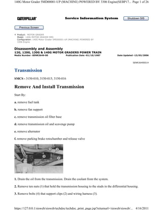
- 1. Disassembly and Assembly 12G, 120G, 130G & 140G MOTOR GRADERS POWER TRAIN Transmission SMCS - 3150-010; 3150-015; 3150-016 Remove And Install Transmission Start By: a. remove fuel tank b. remove fan support c. remove transmission oil filter base d. remove transmission oil and scavenge pump e. remove alternator f. remove parking brake rotochamber and release valve 1. Drain the oil from the transmission. Drain the coolant from the system. 2. Remove ten nuts (1) that hold the transmission housing to the studs in the differential housing. 3. Remove bolts (4) that support clips (2) and wiring harness (3). Shutdown SIS Previous Screen Product: MOTOR GRADER Model: 140G MOTOR GRADER 5MD Configuration: 140G Motor Grader 5MD00001-UP (MACHINE) POWERED BY 3306 Engine Media Number -SENR3649-00 Publication Date -01/10/1987 Date Updated -13/03/2006 SENR36490014 Page 1 of 26 140G Motor Grader 5MD00001-UP (MACHINE) POWERED BY 3306 Engine(SEBP17... 4/16/2011 https://127.0.0.1/sisweb/sisweb/techdoc/techdoc_print_page.jsp?returnurl=/sisweb/sisweb/...
- 2. 4. Remove bolts (6) and retainer (7) that hold couplings (8) to the transmission. 5. Loosen nuts (5) and slide couplings (8) free of the transmission. Left control cables (9) out of the links on the transmission control valves. 6. Fasten a hoist to the lifting eyes on the transmission. Remove tube assembly (13). 7. Disconnect hose assemblies (12). 8. Remove twelve bolts (10) that hold the transmission to the flywheel housing. 9. Move the transmission away from the engine and off the studs in the differential housing. Remove transmission assembly (11). Weight of the transmission is 680 kg (1500 lb.). NOTE: The following steps are for the installation of the transmission. 10. Fasten a hoist to the lifting eyes on the transmission. Lower transmission (11) into position in the machine. 11. Move the transmission onto the studs in the differential housing and into the flywheel housing. NOTE: To put the splines on the transmission adapter in alignment with the flywheel, turn the transmission oil pump shaft to put the splines in the transmission in alignment with the splines on the differential input shaft, the following procedure can be used: a. drain the oil from the tandem housings b. remove the axles c. turn the differential input shaft with a prybar or a screwdriver while the transmission is being installed on the studs of the differential housing. Page 2 of 26 140G Motor Grader 5MD00001-UP (MACHINE) POWERED BY 3306 Engine(SEBP17... 4/16/2011 https://127.0.0.1/sisweb/sisweb/techdoc/techdoc_print_page.jsp?returnurl=/sisweb/sisweb/...
- 3. d. install the axles and fill the tandem housings with oil to their correct levels. 12. Install twelve bolts (10) that hold the transmission to the flywheel housing. 13. Connect hose assemblies (12). 14. Install tube assembly (13). 15. Put control cables (9) in position on the valve links. Put couplings (8) in position on the transmission housing. Tighten nuts (5) against the couplings. Put retainer (7) in position over the couplings. Install volts (6) that hold the retainer to the transmission. 16. Put wiring harness (3) and clips (2) up against the transmission and install bolts (4). 17. Install ten nuts (1) that hold the transmission to the differential housing. 18. Fill the transmission with oil to its correct level. Fill the cooling system with coolant to its correct level. End By: a. install transmission oil filter base b. install parking brake rotochamber and release valve c. install fan support d. install alternator e. install transmission oil and scavenge pump f. install fuel tank Disassemble Transmission Page 3 of 26 140G Motor Grader 5MD00001-UP (MACHINE) POWERED BY 3306 Engine(SEBP17... 4/16/2011 https://127.0.0.1/sisweb/sisweb/techdoc/techdoc_print_page.jsp?returnurl=/sisweb/sisweb/...
- 4. Start By: a. remove transmission 1. Install the transmission on tooling (C). Remove bolts (1) and the lockwashers that hold the cover to the transmission. Remove cover (2). 2. Remove links (3) from the transmission hydraulic control valves. Page 4 of 26 140G Motor Grader 5MD00001-UP (MACHINE) POWERED BY 3306 Engine(SEBP17... 4/16/2011 https://127.0.0.1/sisweb/sisweb/techdoc/techdoc_print_page.jsp?returnurl=/sisweb/sisweb/...
- 5. 3. Remove bolts (8) and plates (7). Move the four sleeves (5) free of the transmission hydraulic control valves. NOTE: Do not remove bolts (4) and (6) at this time. Bolts (4) and (6) hold the control valves to the transmission. 4. Install a 3/8" - 16 NC forged eyebolt in the transmission case. Install tooling (B) in the eyebolt. 5. Install tooling (A) on the transmission case and on the control valves. Connect tooling (B) to tooling (A) as shown. Remove bolts (4) and (6). Remove transmission hydraulic control valves (9) with tooling (B). Weight is 41 kg (90 lb.). See Disassembly Hydraulic Control Valves for disassembly of the control valves. 6. Remove the four sleeves from the transmission. Fasten tooling (D) to the lifting eyes on top of the transmission. Remove the bolts that hold the transmission to tooling (C). Remove the bolts and cover (10). 7. Install two 1/2" - 13 NC forged eyebolts and two nuts in the transmission on top of the output flange. Fasten tooling (D) to the two eyebolts. 8. Turn the transmission on its end with tooling (D). Put the transmission in position on tooling (E). Remove tooling (D) and the eyebolts. Page 5 of 26 140G Motor Grader 5MD00001-UP (MACHINE) POWERED BY 3306 Engine(SEBP17... 4/16/2011 https://127.0.0.1/sisweb/sisweb/techdoc/techdoc_print_page.jsp?returnurl=/sisweb/sisweb/...
- 6. 9. Remove O-rings (11) and O-ring (12) from the housing. 10. Remove bolt (13) and bolt (14) that hold the planetary transmission in the transmission case. 11. Install two 5/8" - 11 NC forged eyebolts (15) in the housing. Fasten a hoist to the eyebolts. 12. Remove the planetary transmission from the transmission case. Weight is 254 kg (560 lb.). 13. Put the transmission on three blocks. 14. Remove bolts (16). Remove O-ring seal (18). Lift housing (17) enough to remove springs (19) and plungers (20). Remove the housing. Weight is 39 kg (85 lb.). Remove the O-ring seal that is under the flange on housing (17). Make sure the input gear for the planetary transmission is on top of the blocks. If the input gear is not on top of the blocks, other components can fall out the bottom of the transmission when a retaining ring is removed. Page 6 of 26 140G Motor Grader 5MD00001-UP (MACHINE) POWERED BY 3306 Engine(SEBP17... 4/16/2011 https://127.0.0.1/sisweb/sisweb/techdoc/techdoc_print_page.jsp?returnurl=/sisweb/sisweb/...
- 7. 15. Remove bolts (22). Bend the locks (23) away from bolts (21). Remove bolts (21) and locks (23). 16. Remove hub (25). Remove four discs (24) and three plates (26). These discs and plates are for the parking brake clutch. 17. Install tooling (F) as shown against plate (29). Put springs (28) in compression with tooling (F) and a press. 18. Remove retaining ring (27). Slowly release the compression on springs (28). Remove tooling (F). Remove the plate and the springs. Page 7 of 26 140G Motor Grader 5MD00001-UP (MACHINE) POWERED BY 3306 Engine(SEBP17... 4/16/2011 https://127.0.0.1/sisweb/sisweb/techdoc/techdoc_print_page.jsp?returnurl=/sisweb/sisweb/...
- 8. 19. Remove cage (30) from the hub. Remove O-ring seal (31) and the internal ring that is under the O- ring seal. 20. Remove external ring (32) from the hub. 21. Remove piston (34). 22. Remove ring gear (33). 23. Remove piston (36). Remove the inserts from the piston. 24. Remove balls (35) from the housing. Page 8 of 26 140G Motor Grader 5MD00001-UP (MACHINE) POWERED BY 3306 Engine(SEBP17... 4/16/2011 https://127.0.0.1/sisweb/sisweb/techdoc/techdoc_print_page.jsp?returnurl=/sisweb/sisweb/...
- 9. 25. Remove four discs (37) and four plates (38). These plates and discs are for the No. 7 clutch. 26. Remove retaining ring (40) with a screwdriver. 27. Remove hub (39) from the shaft. 28. Install two 3/8" - 16 NC forged eyebolts (43) in carrier (44). Remove the carrier. Remove the eyebolts. 29. Remove retaining ring (41) with a screwdriver. Remove bearing (42) from the carrier. 30. Move pin (46) into shaft (45) with a punch and a hammer. Remove shaft (45) from the carrier. 31. Remove gear (48) and thrust washers (47). Remove the bearing from the gear. 32. Repeat Steps 30 and 31 for the other gears. Remove the pins from the shafts. Page 9 of 26 140G Motor Grader 5MD00001-UP (MACHINE) POWERED BY 3306 Engine(SEBP17... 4/16/2011 https://127.0.0.1/sisweb/sisweb/techdoc/techdoc_print_page.jsp?returnurl=/sisweb/sisweb/...
- 10. 33. Remove housing (50). Remove the inserts from the housing. 34. Remove springs (51). Remove ring gear (49). 35. Remove the four discs and the three plates. These plates and discs are for the No. 6 clutch. 36. Remove piston (52) from the housing. 37. Remove ring (54) and ring (53) from the piston. 38. Remove sun gear (55) from the shaft. Page 10 of 26 140G Motor Grader 5MD00001-UP (MACHINE) POWERED BY 3306 Engine(SEBP... 4/16/2011 https://127.0.0.1/sisweb/sisweb/techdoc/techdoc_print_page.jsp?returnurl=/sisweb/sisweb/...
- 11. 39. Remove housing (56). 40. Remove bolts (57) from bearing cage (58). Remove the bearing cage. 41. Remove springs (61). Remove dowels (60). 42. Remove two discs (59) and plate (62). These discs and this plate are for the No. 5 clutch. 43. Remove ring gear (63). 44. Remove piston (64). Remove the rings from the piston. 45. Remove housing (65). Remove the piston from the under side of the housing. Remove the rings from the piston. 46. Remove springs (66). Remove two discs (68) and plate (67). These discs and this plate are for the No. 4 clutch. 47. Remove the cage from carrier (69). Remove the ring from the cage. Remove carrier (69). Remove dowels (70). Page 11 of 26 140G Motor Grader 5MD00001-UP (MACHINE) POWERED BY 3306 Engine(SEBP... 4/16/2011 https://127.0.0.1/sisweb/sisweb/techdoc/techdoc_print_page.jsp?returnurl=/sisweb/sisweb/...
- 12. 48. Turn the carrier and the ring gear over. 49. Move spring pins (73) down with a punch and a hammer. 50. Put retaining ring (72) into compression with pliers. Remove ring gear (71) from the carrier. 51. Remove the retaining ring. 52. Remove retaining ring (76) from the bearing. 53. Remove bearing (74) from the carrier. 54. Move the pins that hold shafts (75) in the carrier into the shafts. Remove the shafts. Remove gears (78). Remove thrust washers (77). 55. Remove the bearings from the gears. 56. Remove two dowels (80) from housing (79). 57. Remove housing (79). Remove piston (81) from the housing. Remove the two rings from the piston. Page 12 of 26 140G Motor Grader 5MD00001-UP (MACHINE) POWERED BY 3306 Engine(SEBP... 4/16/2011 https://127.0.0.1/sisweb/sisweb/techdoc/techdoc_print_page.jsp?returnurl=/sisweb/sisweb/...
- 13. 58. Remove springs (82). 59. Remove two discs (84) and plate (83). These discs and this plate are for the No. 3 clutch. 60. Remove ring gear (85). 61. Remove end plate (86). 62. Remove retaining ring (88) with a screwdriver. 63. Remove center shaft (87) from the planetary and the carrier. Page 13 of 26 140G Motor Grader 5MD00001-UP (MACHINE) POWERED BY 3306 Engine(SEBP... 4/16/2011 https://127.0.0.1/sisweb/sisweb/techdoc/techdoc_print_page.jsp?returnurl=/sisweb/sisweb/...
- 14. 64. Remove gear (92) from the center shaft. Remove bearing (89) from the gear. Remove retaining ring (90) from the bearing. 65. Remove gear (91) from the center shaft. 66. Remove retaining ring (94) with a screw-driver. 67. Remove carrier (93) from the input gear for the transmission. 68. Move the pins that hold the shafts to the carrier into the shafts with a punch and hammer. 69. Remove shafts (98) and (102). Remove gears (97) and (101). 70. Remove thrust washers (95) and (99) from each side of the gears. 71. Remove two bearings (100) from gears (101). Remove bearing (96) from gears (97). 72. Put cage (105) and the input gear in position on cover (10). Install the nuts that hold the cage to the cover. Put the cover in a vise as shown. 73. Remove nut (104) with tooling (G). Remove the nut and the lock. Remove the bearing and input Page 14 of 26 140G Motor Grader 5MD00001-UP (MACHINE) POWERED BY 3306 Engine(SEBP... 4/16/2011 https://127.0.0.1/sisweb/sisweb/techdoc/techdoc_print_page.jsp?returnurl=/sisweb/sisweb/...
- 15. gear (103) from the cage. Remove the spacer and the other bearing from the cage. Remove the cage from the cover. Remove the bearing for the center shaft from the cage. Remove the O-ring seal from the cage. Assemble Transmission 1. Install O-ring seal (106) on cage (105). Install bearing (107) for the center shaft with tooling (A). 2. Install bearing (108) and spacer (109) on cage (105). 3. Put the cage in position in cover (10). Page 15 of 26 140G Motor Grader 5MD00001-UP (MACHINE) POWERED BY 3306 Engine(SEBP... 4/16/2011 https://127.0.0.1/sisweb/sisweb/techdoc/techdoc_print_page.jsp?returnurl=/sisweb/sisweb/...
- 16. NOTE: Cover (10) is the cover from the transmission case that is over the studs for cage (105). 4. Install the nuts that hold the cover to the cage. Put the cover in position in a vise. 5. Install input gear (103) and bearing (110) on the cage. Put 4S9416 Anti-Seize Compound on the face and threads of the nut for the bearing. Install the lock and the nut that hold the bearing. Tighten the nut with tool (B) to a torque of 230 ± 20 N·m (170 ± 15 lb.ft.). Bend the tab of the lock into the nut. 6. Remove the cage from the cover. Remove the cover from the vise. Put the cage and the input gear in position on three blocks as shown. 7. Install the bearings in gear (97) and (100). Install the gears and the thrust washers in carrier (93). Install shafts (98) and (102) in the carrier and the bearings for the gears. Install the pins (110) that hold the shafts to the carrier. Put carrier (93) in position on the input gear. Install the retaining ring that holds it to the input gear. NOTICE The pins that hold the shafts to the carriers must be installed even with the outer surface of the carrier. If they are installed further, they will prevent oil flow for lubrication to the gears. This is the same on all pins for carriers in this transmission. Page 16 of 26 140G Motor Grader 5MD00001-UP (MACHINE) POWERED BY 3306 Engine(SEBP... 4/16/2011 https://127.0.0.1/sisweb/sisweb/techdoc/techdoc_print_page.jsp?returnurl=/sisweb/sisweb/...
- 17. 8. Install gear (91) on center shaft (87). Heat bearing (89) in oil to a temperature of 135°C (275°F). Install the bearing on gear (92) so the face of the bearing is even with the face of the gear. Install ring (90) on the bearing. Install the gear on the center shaft. 9. Install center shaft (87) and the gears and bearing in the carrier. 10. Install retaining ring (88) that holds the bearing to the carrier. 11. Install ring gear (85). 12. Install the end plate on the input gear. 13. Install two discs (84) and one plate (83) on the end plate starting with a disc. These discs and this plate are for the No. 3 clutch. NOTICE Put clean SAE 10 oil on all discs and the plates when they are installed. Page 17 of 26 140G Motor Grader 5MD00001-UP (MACHINE) POWERED BY 3306 Engine(SEBP... 4/16/2011 https://127.0.0.1/sisweb/sisweb/techdoc/techdoc_print_page.jsp?returnurl=/sisweb/sisweb/...
- 18. 14. Install springs (82). Install the dowels in housing (79). Install the inner and the outer ring seals on piston (81). Install piston (81) in housing (79). Install housing (79). Make sure springs (82) are in their correct locations in the end plate and piston (81). 15. Install bearings (111) in gears (78). Install gears (78) and thrust washers (77) in carrier (69). 16. Install shafts (75) in the carrier and the bearings for the gears. Install the pins that hold the shafts in the carrier. 17. Turn the carrier over. Install the ring on bearing (74). Install the bearing in the carrier. 18. Install ring (72) on the carrier. Put the ring in compression. Install ring gear (71) on the carrier and over the ring. Release the ring to hold the gear. 19. Hit pins (71) with a punch and a hammer from the other side to hold the ring gear to the gear on the carrier. Install bearing (74) in carrier (69) with the retaining ring that holds it. 20. Install the ring on cage (112). Install the cage in the bearing for the carrier. 21. Put the carrier and ring gear (71) in position over the gears in carrier (93). Page 18 of 26 140G Motor Grader 5MD00001-UP (MACHINE) POWERED BY 3306 Engine(SEBP... 4/16/2011 https://127.0.0.1/sisweb/sisweb/techdoc/techdoc_print_page.jsp?returnurl=/sisweb/sisweb/...
- 19. 22. Install the dowels that hold the No. 3 and No. 4 clutch plates in alignment. 23. Install two discs (113) and one plate (114) starting with a disc. These discs and this plate are for the No. 4 clutch. 24. Install springs (66) in their correct locations in housing (79). 25. Install the inner and the outer ring seals on pistons (52) and (64). Install piston (64) in housing (56). 26. Put housing (56) in position over the dowels and springs. Make sure the springs are in their correct locations in the housing and in piston (64). Install piston (52) in housing (56). 27. Install ring gear (115) over the gears in carrier (81). Install two discs (59) and plate (62) on the piston starting with a disc. These discs and this plate are for the No. 5 clutch. Page 19 of 26 140G Motor Grader 5MD00001-UP (MACHINE) POWERED BY 3306 Engine(SEBP... 4/16/2011 https://127.0.0.1/sisweb/sisweb/techdoc/techdoc_print_page.jsp?returnurl=/sisweb/sisweb/...
- 20. 28. Put bearing cage (58) in position over the cage on the center shaft. 29. Install bolts (57) that hold the bearing cage to the carrier. 30. Install springs (61) in the piston. Install dowels (60) that hold the plates for the No. 5 and No. 6 clutch in alignment. Put housing (56) in position over the dowels and the springs. Make sure the springs are in their correct locations in the housing. Put gear (55) in position on the center shaft. 31. Install the inner and the outer ring seals on piston (52). Install piston (52) in housing (56). 32. Install ring gear (49). Install four discs (116) and three plates (117) on the piston starting with a disc. These discs and plates are for the No. 6 clutch. Install the springs in their correct locations in piston (52). 33. Install bearings (118) in gears (48). Install the gears and thrust washers (47) in carrier (44). 34. Install shafts (45) that hold the gears in the carrier. Install the pins that hold the shafts in the carrier. 35. Turn the carrier over. Lower the temperature of bearing (42). Install the bearing in the carrier. Install the ring that holds the bearing in the carrier. Install the carrier over the center shaft and gear (55). Page 20 of 26 140G Motor Grader 5MD00001-UP (MACHINE) POWERED BY 3306 Engine(SEBP... 4/16/2011 https://127.0.0.1/sisweb/sisweb/techdoc/techdoc_print_page.jsp?returnurl=/sisweb/sisweb/...
- 21. 36. Install the inserts in housing (119). Put the housing in position over the dowels and the springs. Make sure the springs are in their correct locations in the housing. 37. Put hub (39) in position over the center shaft. Push down on the housings to put the springs in compression. Lift up on the center shaft. Install the ring that holds hub (39) to the center shaft. 38. Put balls (35) in position on the inserts in the housing. Install the dowels in the housing. Install the inserts in piston (36). Put piston (36) in position on the balls. 39. Install four plates (37) and four discs (38) over the hub starting with a plate. These plates and discs are for the No. 7 clutch. 40. Install ring gear (33) over the plates and the discs. NOTE: Ring gear (33) can be installed before the discs and plates are installed. 41. Put piston (34) in position over the plates and the discs for the No. 7 clutch. 42. Install four discs (24) and three plates (26) starting with a disc. These plates and discs are for the parking brake clutch. Page 21 of 26 140G Motor Grader 5MD00001-UP (MACHINE) POWERED BY 3306 Engine(SEBP... 4/16/2011 https://127.0.0.1/sisweb/sisweb/techdoc/techdoc_print_page.jsp?returnurl=/sisweb/sisweb/...
- 22. 43. Install the internal ring and the O-ring seal on the small diameter of cage (30). Install the ring on the large diameter of cage (30). 44. Put cage (30) in position on hub (25). Put the hub and the cage in position on a press. 45. Put springs (28) and plate (29) in position on cage (30). 46. Install tooling (C) on the press and against the plate as shown. 47. Put the springs in compression with tooling (C) and the press. 48. Install retaining ring (27) on cage (30). Slowly release the compression on the springs and remove the tooling and the cage and hub from the press. 49. Turn the hub and cage over. Install two locks (29) and four bolts (21) that hold the hub to the cage. Page 22 of 26 140G Motor Grader 5MD00001-UP (MACHINE) POWERED BY 3306 Engine(SEBP... 4/16/2011 https://127.0.0.1/sisweb/sisweb/techdoc/techdoc_print_page.jsp?returnurl=/sisweb/sisweb/...
- 23. Bend the locks against the bolts. Install the cage and hub (25) in hub (39). 50. Install fourteen washers and bolts (22) that hold the hub (25) to ring gear (64). Tighten bolts (22) to a torque of 50 ± 3 N·m (38 ± 2 lb.ft.). 51. Install two 5/8" - 11 NC forged eyebolts in housing (17). Install the two large O-ring seals on housing (17). 52. Fasten a hoist to the eyebolts. Put the housing in position over the dowels. Install the springs and plungers (20) before the housing is completely installed. 53. Install twelve washers and bolts (16). Tighten the bolts to a torque of 115 ± 7 N·m (85 ± 5 lb.ft.). 54. Install three O-ring seals (120) on the face of the housing. NOTICE Be sure that the parking brake lever enters the notch in the housing when the transmission is put into position in the transmission case. Page 23 of 26 140G Motor Grader 5MD00001-UP (MACHINE) POWERED BY 3306 Engine(SEBP... 4/16/2011 https://127.0.0.1/sisweb/sisweb/techdoc/techdoc_print_page.jsp?returnurl=/sisweb/sisweb/...
- 24. 55. Lift the transmission with a hoist and put it in position in the transmission case. 56. Remove the hoist and the two eyebolts. Install the bolts that hold the transmission in the case. 57. Install two 1/2" - 13 NC forged eyebolts and two nuts in the transmission case on top of the output flange. Install a strap around the transmission case and through the two eyebolts. 58. Fasten tooling (D) to the transmission case. Turn the transmission so it is in an up position. 59. Put cover (121) in position on the transmission case. Put the transmission in position on tooling (E). Install the bolts that hold the transmission to tool (E). 60. Remove tooling (D) and the straps. Install the sleeves in the transmission case. Page 24 of 26 140G Motor Grader 5MD00001-UP (MACHINE) POWERED BY 3306 Engine(SEBP... 4/16/2011 https://127.0.0.1/sisweb/sisweb/techdoc/techdoc_print_page.jsp?returnurl=/sisweb/sisweb/...
- 25. 61. Install a 3/8" - 16 NC forged eyebolt in the cover for the transfer gears as shown. 62. Install tooling (G) in the eyebolt. 63. Install tooling (F) on the transmission and on the transmission hydraulic control valves as shown. Connect tooling (G) to tooling (F) on the control valves. 64. Put transmission hydraulic control valves (9) in position on the transmission. 65. Install bolts (4) and bolts (6) that hold the transmission hydraulic control valves to the transmission. Tighten the bolts to a torque of 48 ± 4 N·m (35 ± 3 lb.ft.). 66. Push four sleeves (5) into their correct locations in the control valves. 67. Install plates (7) in their correct locations in the grooves of sleeves (5). Install bolts (8) that hold the sleeves and the plates. Tighten bolts (88) to a torque of 30 ± 4 N·m (22 ± 3 lb.ft.). 68. Put links (122) in position in stems (3) for the control valves. Tighten the links. 69. Put the gasket and cover (2) in position on the side of the transmission. Page 25 of 26 140G Motor Grader 5MD00001-UP (MACHINE) POWERED BY 3306 Engine(SEBP... 4/16/2011 https://127.0.0.1/sisweb/sisweb/techdoc/techdoc_print_page.jsp?returnurl=/sisweb/sisweb/...
- 26. 70. Install bolts (1) that hold the cover to the transmission. End By: a. install transmission Copyright 1993 - 2011 Caterpillar Inc. All Rights Reserved. Private Network For SIS Licensees. Sat Apr 16 18:41:51 UTC+0700 2011 Page 26 of 26 140G Motor Grader 5MD00001-UP (MACHINE) POWERED BY 3306 Engine(SEBP... 4/16/2011 https://127.0.0.1/sisweb/sisweb/techdoc/techdoc_print_page.jsp?returnurl=/sisweb/sisweb/...