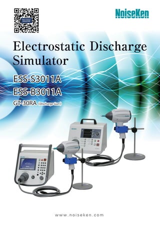
Noiseken esd simulator

ESD Simulators Product Overview Static electricity is generated along objects moving and the objects consist of electric configuration of plus and minus. When this configuration falls into disorder and inclines to the one polarity, the static electricity is generated and this phenomenon is called as electrification. The electrification is generated as result of contact, rubbing and exfoliating mainly. Also, there is one another phenomenon which is called as induced electrification in the meaning of the static electricity. In addition, although sometime, spark phenomena which may be generated when taking a sweater off and touching onto a door knob of a vehicle in dry condition are called as static electricity as well, it should be called as “Electrostatic discharge (ESD)” correctly. In our ordinary lives, 30kV electricity can be easily generated only with putting shoes on and walking on a carpet. “NoiseKen” ESD simulators can reproduce and simulate the ESD from a charged human body intentionally for testing whether electronic equipments become malfunctioned or work correctly with the ESD influence, and the simulators conform to IEC61000-4-2 Standard which is standardized by International Electrotechnical Committee (IEC).

Recommended
More Related Content
What's hot
What's hot (20)
Similar to Noiseken esd simulator
Similar to Noiseken esd simulator (20)
More from NIHON DENKEI SINGAPORE
More from NIHON DENKEI SINGAPORE (20)
Recently uploaded
Recently uploaded (20)
Noiseken esd simulator
- 2. ) (
- 3. ) w w w . n o i s e k e n . c o m
- 4. 2 w w w. n o i s e k e n . c o m [Check 1] Check high voltage output Confirm error to the set value. [Check 2] Check withstanding voltage Confirm whether withstanding voltage is normal or defective The output and defectiveness are checked upon insertion of the discharge gun to the attached gun holder. [Check 3] Check discharge relay operation Confirm whether the relay is exhausted or still available. Confirmable by touch of the discharge gun to the check terminal on the generator and discharge. Photo of the operation Whether the gun head corresponds to IEC or ISO ? What values are the charge capacitor and discharge resistor ? Indicated on the display of the generator ESD Simulator ESS-S3011A GT-30RA EMC test equipment to evaluate the resistibility of electronic equipments when en- ergy charged on a human body or object is discharged to the electronic equipment. This can be available for evaluating malfunctions or functions declines of electronic equipment against the ESD. Programmable simulator to ease some complicated tests. The output voltage is up to 30kV and performable IEC61000-4-2 ISO 10605 Standardscompliant tests. ● “3 pre-checking function” to make sure the more confirmable test ● “CR constant indicator” to make sure the correct unit attachment ● One-touch exchange of gun head and CR unit realized ● “Ten-key Rotary knob” to ease the setting. ● “Infra-red Remote Controller” to realize the setting remotely from the generator (Standard attached). ● “Discharge Detecting Function” to realize the air-discharge confirmation. ● “Lightest discharge gun in the market” to lighten the continuous operation (Excluding the cable and connector) ● “White LED Irradiator” to facilitate the visualization of the discharging areas. ● “ Control Software” to enable the test result reporting and control with PC. * The software is scheduled to be downloaded freely from our web-site (The connection cable is necessary in addition). * C (Capacitor) and R (Resistor) for the discharge gun is one-body unit. * ISO 10605 compliant test can be realized with the optional parts in addition. Smart model equipped high function extendibility Feature ● More insurable test realized ! “3 pre-checking function” built-in ● “CR constant indicator” to make sure the correct unit attachment. *Probe stand for the discharge gun is option.
- 5. E L E C T R O S T A T I C D I S C H A R G E S I M U L A T O R 3 w w w. n o i s e k e n . c o m Most of the operation can be controlled by the remote controller. LED irradiator built-in to shine the discharging points More light and comfortable handling One-touch exchangeable CR unit LED irradiator to visualize the discharge (Change the color from red to green upon the discharge) Easily exchangeable gun head Polarity change Voltage Up / Down Air/Contact discharge change Gun trigger function Count reset Sequence change F key assignment etc. Start/Stop The discharge gun has been renewed completely to materialize a considerable Weight re- duction and best gravity balance. Human load in the operation can be remarkably reduced comparing to the previous model. Please realize it on-hand actually. Also, an event of air discharge can be visualized with LED light on the body in this new discharge gun although the previous one has to be confirmed only with human eyes. In addition, various functions are added like one-touch exchange of CR unit, LED irradiator to shine the discharging points, etc. ● Lighter and more user-friendly discharge gun ● “Infra-red Remote Controller” standard attached to realize the setting remotely from the generator ESS-S3011A GT-30RA
- 6. 4 w w w. n o i s e k e n . c o m Model Name 12-00009A Discharge tip (GT-30R series Spherical 30mm) 03-00072A Gun head to GT-30R series for constant 2kΩ test 06-00074B CR unit (150pF - 2kΩ) to GT-30R series 06-00076B CR unit (330pF - 2kΩ) to GT-30R series 06-00075B CR unit (330pF - 330Ω) to GT-30R series Gun head for constant 2kΩ test CR unit Discharge tip (Spherical 30mm) ● ISO 10605 standard compliant discharge gun package available ● High visibility LCD panel and operatability Reviewed the past operatability so that more easy and optimal operation can be realized. In 1 IEC STANDARD in MAIN MENU, since the test levels are preset, the test parameters can be set easily only with selection of the test level. In 2 MANUAL, voltage and number of times of the test can be selected and also the set conditions can be recorded. Sweeping discharges can be set as well. In 3 SEQUENCE, the set conditions in MANUAL can be recalled for combining them so as to realize the arbitrary sequential tests. In addition, varied functions like setting for gun trigger, automated ESD eliminator, etc. are equipped. Specification Options for ISO 10605 Standard compliant test Parameter Specification Polarity Positive / Negative Output voltage 0.20kV ∼ 30.0kV±5% (30.5kVmax) ∼10.0kV : 0.01kV step ∼30.0kV : 0.1kV step Repetition cycle 0.05s ∼ 600s±10% / Manual Set step : 0.01s (0.05 ∼ 9.99s), 0.10s (10.0 ∼ 600.0s) No. of time of discharge 1∼60,000 times, Preset 1 time step or continuous preset Discharge mode Contact discharge / Air discharge Radiation level mode NORMAL mode / EXTRA mode Trigger mode Gun trigger / Main trigger / External trigger Operation panel Color LCD / Push-buttons (Partially lighting) Gun holder Standard attached (to hold the discharge gun Model GT-30RA) Radiation mode select switch Extra / Normal switching function built-in Discharge detection Discharge detection function in air-discharge equipped Pre-checking function Following 3 steps function equipped (by user operation. Not the calibration but just checking) SETP1 : High voltage output checking STEP2 : Withstanding voltage checking STEP3 : Discharge relay operation checking CR Gun head checking CR constant and gun head recognizable (with an indicator to prevent the wrong combination) Parameter Specification IEC STANDARD Contact discharge mode : 2.0kV, 4.0kV, 6.0kV and 8.0kV step test mode Air discharge mode : 2.0kV, 4.0kV, 8.0kV and 15.0kV step MANUAL Contact / Air discharge mode, Arbitrary setting during 0.2kV∼30.0kV test mode Sweeping function built-in, Recordable up to 99 units SEQUENCE Enables to operate units set in MANUAL mode continuously. test mode Max. 22 steps / 1 program and the programs recordable up to 20. Warning lamp Lighting at voltage output from the generator. Blinking at electro-static discharging Charge capacitor / resistor 150pF±10%, 330Ω±10%(Built-in CR unit for discharge gun GT-30RA) Charge resistor in generator 10MΩ(Totally 53Ω in combination with 43MΩ in discharge gun)* AUX connector D-SUB 15pins female connector (for connecting to patolight, automated ESD eliminator, external interlock input, external trigger input terminal) Optical communication Optical connector (serial interface) for connecting to PC connector Power supply / consumption AC100V∼AC240V 50Hz / 60Hz ±10% 75VA Dimensions Generator : (W)392mm X (H)312mm X (D)295.3mm (gun holder included) Discharge gun : (W)83.3mm X (H)217.2mm X (D)229.3mm Weight Generator : approx. 7.5kg Discharge gun : approx. 800 g (cable and connector excluded) * The constant depends on combination with CR unit for the discharge gun ESS-S3011A GT-30RA
- 7. E L E C T R O S T A T I C D I S C H A R G E S I M U L A T O R 5 w w w. n o i s e k e n . c o m Parameter Specification Modell ESS-B3011A Output voltage 0.20kV∼30.0kV±5%(30.5kVmax) Polarity Positive / Negative Repetition cycle 0.05s∼9.99s±10%, 0.01s step / Manual No. of time of discharge 1∼999 times, Preset 1 time step or continuous preset Discharge mode Contact discharge / Air discharge Trigger mode Gun trigger / Main trigger Operation panel Indicator : 5X7 Dot matrix LED / Operation : Push buttons (Partially lighting) Radiation mode select switch Extra / Normal switching function built-in Discharge detection Discharge detection function in air-discharge equipped. Pre-checking function High voltage output checking function (by user operation. Not the calibration but just checking) CR Gun head CR constant and gun head recognizable checking (to prevent the wrong combination without indicator) IEC LEVEL Contact discharge mode : 2.0kV, 4.0kV, 6.0kV and 8.0kV step Switching function Air discharge mode : 2.0kV, 4.0kV, 8.0kV and 15.0kV step Warning lamp Lighting at voltage output from the generator. Blinking at electro-static discharging Chargecapacitor/resistor 150pF±10%, 330Ω±10% (Built-in CR unit for discharge gun GT-30RA) Charge resistor in generator 10MΩ (Totally 53Ω in combination with 43MΩ in discharge gun)* Power supply / consumption AC100V∼AC240V ±10% 50Hz / 60Hz 62VA Dimensions Generator : (W)270mm X (H)263mm X (D)200mm Discharge gun : (W)83.3mm X (H)217.2mm X (D)229.3mm Weight Generator : Approx. 4.8kg Discharge gun : Approx. 800g (excluding cable and connector) * Remote control function not built-in. * The constant depends on combination with CR unit for the discharge gun ESD Simulator ESS-B3011A GT-30RA Cost-oriented basic model ESD Simulator the light Weight discharge gun attachable. The output voltage can be selected max. 30kV. And compliant to both EN/IEC61000-4-2 Standard and ISO10605 Standard. ● “Pre-checking function” taking the confirmable test into the account ● “CR constant checking function” (No indicator) to make the correct unit attachment sure ● “Discharge Detecting Function” to realize the air-discharge confirmation. ● “Lightest Discharge Gun in the market” to lighten the continual operation ● “White LED Irradiator” to facilitate the visualization of the discharging area. ● One-touch exchange of gun head and CR unit realized * ISO 10605 compliant test performable with addition of the gun head and CR units (only with ESS-B3011A) Cost-oriented Basic models Specification Discharge output waveform (IEC Standard) *Probe stand for the discharge gun is option. Ip I30 I60 90% Ip 10% Ip 10% Ip tr 10 5 10 15 20 30 40 50 t (ns) I (A) 60 70 80 90 100
- 8. 6 w w w. n o i s e k e n . c o m ESD test environment in conformance with EN/IEC61000-4-2 Standard. Two types for EUT are available, table-top type and floor-standing type so that the environments can support the tests along EUT figures. Since the table is made of wood, influence to the test result should be small (quantitable test result can be ex- pected since the discharge can be realized in state high frequency electromagnetic field is less lost) and the high reproducibility can be expected and realized. Also, versatilely utilized for another tests like impulse noise immunity test, etc. ● ESD test environments in conformance with EN/IEC61000-4-2 stan- dard ● High reproducible tests can be performed ● Can be verstatilely utilized for another tests ESS-801 (Table-top type) Item Model Dimensions Q ty Test table 03-00039A (W) 1600x(H)800x (D) 800mm 1 set Vertical coupling plate 03-00005A (W) 500x(H)500x (t) 1.5mm 1 set Ground plane 03-00007A (W) 1800x(D)1000x (t) 1.5mm 3 pcs. Insulating sheet 03-00004A (W) 1450x(D)650x (t) 0.5mm 1 pc. Discharge resistance cable 05-00054B 2m cable equipped with 470kΩX 2 pcs. 2 pcs. Horizontal coupling plate 03-00020A (W) 1600x(D)800x (t) 1.5mm 1 pc. ESS-801GL (Floor-standing type) Item Model Dimensions Q ty Insulating support 03-00024A (W) 1200x(H)1200x (t) 100mm 1 pc. Floor-standing vertical coupling plate 03-00034A (W) 540x(H)1540x (D) 500mm 1 pc. Ground plane 03-00007A (W) 1800x(H)1000x (t) 1.5mm 3 pcs. Discharge resistance cable 05-00054B 2m cable equipped with 470kΩX 2 pcs 1 pc. Test setup example with ESS-801 * Contents in the set referred to following specification Vertical coupling plate for ESS-801GL Specification ■Option Test environment (Table-top type / Floor-standing type) ESS-801 / 801GL Feature Test Table MODEL : 03-00039A Wooden table to be used for the test to devices under test (DUT). W1600 × H800 × D800mm Ground Reference Plane (GRP) MODEL : 03-00007A Ground plane to be placed just under the wooden table. W1800 × D1000 × t1.5mm × 3 pcs. in 1 set (Made of aluminum) Horizontal Coupling Plate (HCP) MODEL : 03-00020A Metal plate to be placed onto the table in case of the testing to table top devices. W1600 × D800 × t1.5mm × 1 pc.(Made of aluminum) Discharge resistance cable MODEL : 05-00054B Cable to be used for eliminating the ESD on DUT and connect between HCP and GRP 470kΩ × 2 pcs./1 set. Insulating support MODEL : 03-00024A When doing the electrostatic discharge test to floor-standing equipment, to be used for floating the equipment 10cm higher than the ground reference plane. Size : W 1200 × D 1200 × H 100mm Material : Wooden Withstanding loads : 500kg
- 9. E L E C T R O S T A T I C D I S C H A R G E S I M U L A T O R 7 w w w. n o i s e k e n . c o m Used for floating EUT 10cm upper than the ground plane in case of testing to floor-standing EUT Size : W100 × D100 × H100mm Material : Wood Withstanding loads: 500kg Cubic Insulating Block100 MODEL : 03-00029A Adaptor for connecting between probe stand PS-806 or 03-00022B and discharge gun GT-30R series. ●Available discharge gun : GT-30R series Conversion Adaptor for Probe Stand MODEL : 03-00074A Plate to be laid out under tires for the vehicle test W500 × D500 × t1.5mm Aluminum Plate for Test MODEL : 03-00053A Free Arm Gun Stand MODEL : 03-00022B Enable to move discharge gun vertically and horizon- tally to arbitrary desirable discharging point. (Out of ISO Standard) ●Corresponding discharge gun : GT-30R series * Conversion adaptor model 03-00074A is necessary in addition for the attachment to GT-30R series Conductive Mat (for ISO Standard) MODEL : 03-00055A Mat to be laid out in between DUT and GRP for the ESD susceptibility test in the packaging and handling. Surface resistance 107 ~109 Ω W1000 × D500 × t2mm Ground Cable (for ISO Standard) MODEL : 05-00104A Cable to be used for grounding connection required in ISO 10605 (2001). L2000 × W50mm * Not required in ISO 10605 Ed.2 (2008) Coupling Plate for ISO 10605 Annex F MODEL : 03-00065A Coupling plate used for the optional test in ISO 10605 Ed.2 (2008). It consists of a coupling plate (made of copper) and an insulation block. * Ground reference plane is not included. Automated ESD Eliminator MODEL : 01-00013B Enable to eliminate electric charge which has been charged to EUT automatically with connection to ESS- S3011A ●Available model : ESS-S3011A ESD Elimination Brush MODEL : 05-00125A Brush to eliminate the electri- fication on EUT / DUT before starting the test. Insulating Block MODEL : 03-00054A Blocks to float (isolate) wirings of DUT from GRP. W300 × D300 × H50mm, 5 pcs. in 1 set Insulating Support MODEL : 03-00066A Sheet to be laid out in between DUT and GRP for the test to automotive electronics devices. W1450 × D650 × t2mm Probe Stand MODEL:03-00108A Item Specification Dimensions (H)380mm, Pedestal diameter 160mm Weight approx. 4.1 kg Range of movement Vertical: 150mm, Swing angle: 130 ° A probe stand used to fix the discharge gun for ESD Simulator. (Excluded from IEC standard) Because of the articulated type, the discharge gun fixes in any direction. ●Available discharge gun : GT-30R series Option
- 10. 8 w w w. n o i s e k e n . c o m ● For ISO10605 compliant test 1st discharge peak current t1 Current t2 Current 150pF/330Ω 3.75A/kV±10% 2A/kV±30% 1A/kV±30% (t1=30ns) (t2=60ns) 330pF/330Ω 3.75A/kV±10% 2A/kV±30% 1A/kV±30% (t1=65ns) (t2=130ns) 1st discharge peak current t1 Current t2 Current 150pF/2kΩ 3.75A/kV +30%-0% 0.275A/kV±30% 0.15A/kV±50% (t1=180ns) (t2=360ns) 330pF/2kΩ 3.75A/kV+30%-0% 0.275A/kV±30% 0.15A/kV±50% (t1=400ns) (t2=800ns) 2kΩ gun head CR unit for ESD gun GT-30R series ●Available discharge gun : GT-30R series * Please contact us when the other CR constant is required than the right description. * The unit size depends on the capacitor constant. CR Unit M Model CR constant 06-00073B 150pF-330Ω 06-00074B 150pF-2kΩ 06-00075B 330pF-330Ω 06-00076B 330pF-2kΩ 06-00077B 500pF-0Ω 06-00078B 150pF-500Ω 06-00079B 100pF-1.5kΩ 06-00080B 200pF-0Ω Model CR constant 06-00081B 150pF-150Ω 06-00082B 500pF-500Ω 06-00083B 500pF-5kΩ 06-00084B 250pF-100Ω 06-00085B 200pF-100Ω 06-00086B 250pF-0Ω 0 140 120 100 80 60 40 20 Y X 0 20 15 10 5 0 0 20 Y X 15 10 5 200 100 300 500 400 600 800 900 700 Spherical (φ30mm) discharge tip Energy storage capacitor / Discharge resistor values Energy storage capacitor / Discharge resistor values Gun head to be changed according to Standard com- pliant test. 2 kinds for the test with 330Ω(03-00071A) and 2kΩ (03-00072) are lined up. ●Available discharge gun : GT-30R series Gun Head MODEL : 03-00071A / 03-00072A Discharge tips on the gun. Conical (12-00007A) and Round (12-00008A) are stan- dard equipped with GT-30R series. The all 3 tips are standard equipped with GT-30R se- ries. ●Available discharge gun : GT-30R series Discharge Tip MODEL : 12-00007A / 8A / 9A Impulsive Electric Field Adoptor MODEL : 03-00068A Adaptor for simulating static induction as one of noise induc- tive mode.with attachment to the discharge gun (Not standardized in IEC) ●Available discharge gun : GT-30R series Fast Rise Time Adaptor MODEL : 03-00073A Fast Rise Time Adaptor MODEL : 03-00073A Realize faster rise time of the discharge current than IEC61000-4-2 standard value (0.6-1.0ns) around 0.2-0.3ns with attachment to the discharge gun. ●Available discharge gun : GT-30R series ●GT-30R3302KA package contents GT-30R series gun body 03-00071A gun head 03-00072A gun head 06-00073B 150pF-330 ohm CR unit 06-00074B 150pF-2K ohm CR unit 06-00075B 330pF-330 ohm CR unit 06-00076B 330pF-2K ohm CR unit 12-00007A conical tip 12-00008A round tip 12-00009A spherical tip Option
- 11. E L E C T R O S T A T I C D I S C H A R G E S I M U L A T O R 9 w w w. n o i s e k e n . c o m Magnetic field adapter for Ford standard. Connected to GT-30R series discharge gun, it generates transient magnetic fields. ● Available discharge gun : GT-30R series Magnetic Field Adapter MODEL : 03-00070A Item Specification Loop coil diameter 155m Dimensions 168mm(loop outer diameter) 300mm(length) 12.7mm(thickness of the loop) Adaptor for simulating electro- magnetic induction as one of noise inductive mode.with attach- ment to the discharge gun (Not standardized in IEC) ●Available discharge gun : GT-30R series Impulsive Magnetic Field Adaptor MODEL : 03-00069A Holder for discharge gun during the test. Also, can be the pre-checking fixture in combina- tion between ESS-S3011A and GT-30R series. ●Available discharge gun : GT-30R series Gun Holder MODEL : 03-00075A Specialized Case for Discharge Gun MODEL : 09-00006A Specialized Case for putting the discharge gun, CR units and the other related fixtures and carrying them out. ●Available discharge gun : GT-30R series Extension cable for GT-30R MODEL : 05-00047B Extension cable in connection between ESD simulator main unit and its discharge gun. The length is 3m * not compliant with the IEC standard ●Available discharge gun :GT-30R series Warning Lamp MODEL : 11-00014A Caution is alerted with its blinking while the HV circuit is on. ●Available model : ESS-S3011A * The connection is done with DSUB connector. AUX Connector Junction Box MODEL : 05-00052A Enable to connect warning lamp, automated ESD eliminator and external trigger simultaneously ●Available model : ESS-S3011A Optical RS232 Module MODEL : 07-00017A Optical conversion adaptor used for remote control with PC. 5m of optical fiber cable with RS232 interface attached. ●Available model : ESS-S3011A Optical USB Module MODEL : 07-00022A Optical conversion adaptor Used for remote control with PC. 5m of optical fiber cable with USB interface attached. ●Available model : ESS-S3011A Option
- 12. 10 w w w. n o i s e k e n . c o m Load Resistor Mounting Board MODEL : 03-00027A The board to fix the load resistor (MODEL NO. 06-00067A ESD current target) for measuring the discharge current waveform defined in IEC61000-4-2 Standard and ISO 10605 Ed.2 Standard. (not conform- ing to the standard strictly but simply) Dimensions : 0.6m X 0.6m Faraday cage MODEL : FC-200 Farady cage which is defined in IIEC61000-4-2 Stan- dard and ISO 10605 Ed.2 Standard to verify the discharge current waveform. Easy to move with casters equipped to the bottom. Item Specification Power supply AC100V 50Hz/60Hz 3P inlet Equipped with over-current protective breaker Opening Dimensions (W) 410mm X (H) 618mm on door Dimensions / Weight (W)670mm x (H)1612mm x (D) 1509mm Approx. 65kg. 3p outlet X 2 15A MAX Load Resistor Mounting Board MODEL : 03-00052B The board to fix the load resistor (MODEL NO. 06-00067A ESD current target) for measuring the discharge current waveform defined in IEC61000-4-2 Standard and ISO 10605 Ed.2 Standard Dimensions : 1.2m X 1.2m GND Cable Positioner MODEL : 03-00060A Stand to pull and fix the ground cable of discharge gun 0.5m backward at the mid- dle of the cable when calibrating the ESD current. Discharge Gun Mount MODEL : 03-00061B Fixture to load and fix the discharge gun to be Farady cage (FC-200) or load resistor mounting board (03-00052B) ESD Current Target MODEL : 06-00067A Load resistor to measure, verify and calibrate ESD current waveform defined in IEC61000-4-2 Standard and ISO 10605 Ed.2 Standard Parameter Specification 300kHz-1GHz ±0.5dB 1GHz-4GHz ±1.2dB Maximum applied voltage 15kV Conversion ratio 2V/1A (50Ω termination) Weight Approx. 400g ESD Current Target Calibration Set MODEL : 06-00068A Set to calibrate the ESD target (06-00067A) in conformance with IEC61000- 4-2 Ed.2.0 (2008). Coaxial Cable MODEL : 02-00132A High frequency responsible cable to connect ESD target And oscilloscope BNC-SMA connector (02-00133A) is also available as an option Attenuator MODEL : 00-00010A / 00-00011A Attenuator to protect measurement equipment for ESD current waveform. 00-00010A : Attenuation ratio 6dB / SMA connector 00-00011A : Attenuation ratio 20dB / N connector Adaptor (06-00068A) A photo of 06-00067A ESD target and 06-00068A adaptor connected faced to face Attenuator B ESD current target 50Ω coaxial adaptor line Coaxial cable Coaxial cable Input port Output port a a Network Analyzer Attenuator A a : Calibration points with networks analyzer ESD simulator Main unit ≧1200mm ≧1200mm Insertion of 20dB attenuator is recommended for protecting the oscilloscope Faraday cage Appropriate depth for the scope being used 0.6m from the center of the target to each side 0.6m form center of the current target to the each side Coaxial cable connecting as short as possible The discharge return cable should be connected vertically 0.5m under the current target and pulled up right backward Filter Discharge gun Fix the discharge gun with optional probe stand (03-00061B) or the substitute. * Never hold with hand 0.5m Faraday cage of Board to fix the target Discharge gun Oscilloscope 20dB attenuator 6dB Attenuator Conversion connector (SMA – BNC) ESD current target 06-00067A Coaxial cable Connecting method of ESD target Conical tip is used for the discharge 12-00007A (Standard equipped) Connected point of the discharge gun return cable Option
- 13. E L E C T R O S T A T I C D I S C H A R G E S I M U L A T O R 11 w w w. n o i s e k e n . c o m Micro-gap Discharge Tip MODEL : 12-00010A ■ Compatible discharge gun TC-815S, 815R, 815ISO, 815-330, 815-2K, 815S-330, GT-30Rseries (the dedicated cup 03-00103A required) dedicated cup Model:03-00103A *This product cannot be used for the air discharge testing Enabling a more stringent evaluation for the real world ESD immunity Connected to the NoiseKen ESD gun, this tip allows for a waveform with higher peak amplitude and a faster rise time. It is a common view that ESD immunity testing is the most challenging and passing the standard test does not always assure real world immunity. This tip is helpful for more extensive testing against non-standard- ized field events ■ Events you can simulate are ● Loose screws ● Poor insulation coating ● Poor electrical connection between components and others which cause secondary discharges within a very close distance 0 10 20 30 40 50 60 -0.5 0.0 0.5 1.0 1.5 2.0 2.5 3.0 Discharge current [A] Time[ns] Contact 1000μm 30μm 50μm 500μm 100μm 200μm 0 10 20 30 40 50 60 -10 0 10 20 30 40 50 60 70 80 Discharge current [A] Time[ns] Contact 1000μm 30μm 500μm 200μm 100μm spark void hole coating sheet metal discharge tip non perfect connection to the conductive layer (through a coating) spark screw coating gap sheet metal plastic discharge tip loose screw insulating coating Compared to the waveform from the standard contact discharge, a waveform obtained by using this micro-gap tip has a faster rise time. Testing with energy rich pulses for the GHz region μm 1.0E-13 1.0E-12 1.0E-11 1.0E-10 1.0E-09 1.0E-08 1.0E-07 1.0E-06 1.0E-05 current spectral density [A/Hz] frequency [Hz] contact 9 0 + E 0 . 1 8 0 + E 0 . 1 500μm Compared to the contact discharge, discharge through a micro-gap contains a higher level of noises over the higher side of the spectrum Simulated field events Compared to the waveform from the standard contact discharge, a waveform obtained by using this micro-gap tip has a higher peak amplitude. enlarged photo of the micro-gap discharge current energy spectral density light blue(●):discharge through a 500um gap red(●):contact discharge ■ Output waveform (reference) entire waveform waveform leading edge Option
- 14. 12 w w w. n o i s e k e n . c o m The international immunity test standard which applies to electronic equipment against ESD generated directly from a human body or near metal objects in condition chemical fibers carpets or clothings are used in low humidity relatively. This standard assumes cases an charged human body discharges to electronic equipment and testing with the circuit to simulate current waveform generated in such conditions The levels as below. ■ Test level range for the ESD * X can be any level determined by consent between the EUT manuracturer and the simulator supplier Level Test voltage (contact discharge) Test voltage (air discharge) 1 2kV 2kV 2 4kV 4kV 3 6kV 8kV 4 8kV 15kV X Special Special Energy accumulation capacity 150pF (typical) Discharge resistance 330Ω (typical) Output voltage 8kV / Contact discharge, 15kV / Air discharge Tolerance of output voltage ±5% Polarity of output voltage Positive and negative (Switching available) Hold time = 5sec. Discharge mode of operation Single discharges (Discharge interval =1 sec) Waveform of discharge current See right figure 1st peak current Current Current of discharge Rise time (±30%) (±30%) Level Indicated voltage (±15%) lp (±25%) at 30ns at 60ns 1 2kV 7.5A 0.8ns 4A 2A 2 4kV 15A 0.8ns 8A 4A 3 6kV 22.5A 0.8ns 12A 6A 4 8kV 30A 0.8ns 16A 8A The generator must satisfy following specification. ■ Generator specification The characteristics in following table must be verified in order to compare the tests results even among different generators ■ Generator characteristics V Cs S1 Rch Capacitance Cs : 150pF Discharge resistance Rd : 330 Rd S2 Discharge current waveform and its characteristics Simplified diagram of the ESD generator 1. General 2. Test Level 3. Test Generator and Waveform Verification IEC61000-4-2 Ed.2 Test Standard Ip I30 I60 90% Ip 10% Ip 10% Ip tr 10 5 10 15 20 30 40 50 t (ns) I (A) 60 70 80 90 100
- 15. E L E C T R O S T A T I C D I S C H A R G E S I M U L A T O R 13 w w w. n o i s e k e n . c o m 床置き機器の場合 ESD simulator Main unit ≧1200mm ≧1200mm Insertion of 20dB attenuator is recommended for protecting the oscilloscope Faraday cage Appropriate depth for the scope being used 0.6m from the center of the target to each side 0.6m form center of the current target to the each side Coaxial cable connecting as short as possible The discharge return cable should be connected vertically 0.5m under the current target and pulled up right backward Filter Connected point of the discharge gun return cable Discharge gun Fix the discharge gun with optional probe stand (03-00061B) or the substitute. * Never hold with hand 0.5m Faraday cage of Board to fix the target Discharge gun Oscilloscope 20dB attenuator 6dB Attenuator Conversion connector (SMA – BNC) ESD current target 06-00067A Coaxial cable Connecting method of ESD target Conical tip is used for the discharge 12-00007A (Standard equipped) 0.1m Power supply for generator Distance between EUT side and wall must be at least 0.8m Grounding conductor Protective conductor 0.1m height insulation pallet Ground plane 470kΩ resistors VCP 0.5m X 0.5m Plasement of direct discharge EUT 0.1m Power supply for EUT (AC) Placement of indirect discharge to VCP ESD generator Distance between EUT side and wall must be at least 0.8m Placement of indirect discharge to VCP VCP 0.5m×0.5m Grounding conductor Protective conductor EUT 0.1m 0.8m 470k resistors Ground plane Placement of indirect discharge to HCP Wooden table Power supply for EUT(AC) ESD generator Insulation sheetInsulation sheet HCP 1.6m X 0.8m 0.1m Power supply for generator Measure the waveform with an oscilloscope whose band width is 2GHz or more upon use of Fara- day cage and the current target. Attach the discharge electrode directly to the current target and operate the generator with the contact discharge mode. ■ Waveform verification of ESD Generator * It is recommended that insertion of approx. 20dB attenuator for protecting the measurement equipment although it is not specified in IEC Standard. * Float cables from the ground plane with 0.5mm thickness insulation sheet. * Keep GND cable of the discharge gun ≧ 0.2m from any conductive parts other than the ground plane * The isolation transformer for EUT is not specified in IEC Standard. The direct discharge test is electrostatic direct discharge to EUT and examine the influence. Put a wooden table whose height is 0.8m on the ground plane and place horizontal coupling plate (HCP 1.6m × 0.8m). Connect the HCP with resistor 470kΩ × 2 to the ground plane and lay a insulation sheet between the HCP and the EUT. The indirect discharge test is electro- static discharge to the HCP and vertical coupling plate (VCP 0.5m × 0.5m) and examine the influence of EUT. Connect the VCP with resistor 470kΩ × 2 to the ground plane as well. ■ Example of test set-up for table-top equipment Put an insulation pallet whose height is 0.1m onto the ground plane and place EUT on the pallet for the direct discharge test. The indirect discharge test is elec- trostatic discharge to the VCP and examine the influence of EUT. Connect the VCP with resistor 470kΩ × 2 to the ground plane as well. ■ Example of test set-up for floor-standing equipment In case of table-top EUT In case of floor-standing EUT * The isolation transformer for EUT is not specified in IEC Standard. 4. Test setup IEC61000-4-2 Ed.2 Test Standard
- 16. 14 w w w. n o i s e k e n . c o m ■ Climatic and Other Environmental Conditions It is necessary to leave equipment which are brought in from different climatic conditions fully before performing the test. Also, in order to stabilize the discharging condition certainly, it is necessary to fix the climatic conditions in the test room. Fulfillment of the conditions listed in following table must be required to perform testing in conformance with IEC61000-4-2. The tests results are classified into following 4 patterns according to specifications of EUT and operating conditions. 1) Normal operation within the tolerance of the specification 2) Temporary degradation or loss in the operation or the function which is able to be recovered by a self-recovery function 3) Temporary degradation or loss in the operation or the function which needs to be recovered by user intervention or reset in the system. 4) Damage of the system (parts) or software, and unrecoverable degradation in the function due to loss of the data. Generally, as far as the EUT is immune to the ESD during testing and it satisfies the functional requirements according to the product specification after testing, the test result can be perceived as Pass The test report shall contain the test conditions and the result. Ambient temperature 15ºC to 35ºC Relative humidity 30% to 60% Atmospheric pressure 86 kPa (860 mbar) to 106 kPa (1060 mbar) Electromagnetic conditions Level not to affect the test result ■ Test Procedure Direct discharge test : Contact discharge (at 1 second interval) and air discharge Indirect discharge test : Discharge to VCP and HCP At least 10 single discharges shall be applied at 1 second or longer interval in both positive and negative polarities. * A preliminary test which discharges 20 times or more per second may be done in order to select the points to which single discharges should be applied. 5. Test Procedure 6. Evaluation of Test Results and Test Report Notes: This test procedure and test set-up are extracted from IEC61000-4-2 (2009) and JIS C 61000-4-2 standardsed.2.0 (2005) Standard for applying to our products. Please go through the Standards if the more details are required. IEC61000-4-2 Test Standard
- 17. E L E C T R O S T A T I C D I S C H A R G E S I M U L A T O R 15 w w w. n o i s e k e n . c o m 1. General Electrostatic discharges which are generated both in vehicles and while we get on and off there can be factors to cause malfunction of the electrical devices and components. Nowadays, more attention has been paid, as vehicles install more and more electronic devices and components. This Standard provides that static electricity is discharged to the electronic devices or equipment from the charged human body and tests are simulated by electrical circuit to reproduce the electric current waveform at the discharge. In addition to procedures for the immunity tests and evaluations in state that the electronic devices or equipment work while the vehicle is driving, also, the Standard provides tests procedures to evaluate the immunity of the each module against simulated human discharges during the assembly process or in servicing. 2. Test level The following tests levels are reference. The categories are classified according to functional importance of the electronics devices/com- ponents. Component test – Example severity levels for direct contact discharge and direct air discharge (Function performance status) Direct contact discharge Direct air discharge. Test severity level Category 1 Category 2 Category 3 Category 1 Category 2 Category 3 Level 4 ±8kV ±8kV ±15kV ±15kV ±15kV ±25kV Level 3 ±6kV ±8kV ±8kV ±8kV ±8kV ±15kV Level 2 ±4kV ±4kV ±6kV ±4kV ±6kV ±8kV Level 1 ±2kV ±2kV ±4kV ±2kV ±4kV ±6kV Component test – Example severity levels for indirect contact discharge (Function performance status) Direct contact discharge Test severity level Category 1 Category 2 Category 3 Level 4 ±8kV ±15kV ±20kV Level 3 ±6kV ±8kV ±15kV Level 2 ±4kV ±4kV ±8kV Level 1 ±2kV ±2kV ±4kV Vehicle test — Example severity levels for contact discharge and air discharge (Test points accessible only from inside vehicle) Contacts discharge Air discharge Test severity level Category 1 Category 2 Category 3 Category 1 Category 2 Category 3 Level 4 ±6kV ±8kV ±8kV ±8kV ±15kV ±15kV Level 3 ±4kV ±4kV ±6kV ±6kV ±8kV ±8kV Level 2 ±2kV ±2kV ±2kV ±4kV ±4kV ±6kV Level 1 – – – ±2kV ±2kV ±4kV Vehicle test — Example severity levels for contact discharge and air discharge (Test points accessible only from outside vehicle) Contacts discharge Air discharge Test severity level Category 1 Category 2 Category 3 Category 1 Category 2 Category 3 Level 4 ±6kV ±8kV ±8kV ±15kV ±15kV ±25kV Level 3 ±4kV ±6kV ±6kV ±8kV ±8kV ±15kV Level 2 ±2kV ±4kV ±4kV ±4kV ±6kV ±8kV Level 1 – – ±2kV ±2kV ±4kV ±6kV 3. Specification of generator and verification of output waveform Following specification must be satisfied with the simulator for the test. Parameter Specification Output voltage . Contact discharge-(kV) 2kV~15kV Output voltages - Air discharge-(kV) 2kV~25kV Output voltages accuracy (%) ≦5% Polarity Positive and negative Rise time of short circuit current in contact discharge mode(10 % to 90 %) 0.7ns~1ns Holding time ≧5s Storage capacitances(pF) 150pF, 330pF Discharge resistances(Ω) 2kΩ, 330Ω ■ Specification of ESD simulator ISO 10605 Ed. Test Standard
- 18. 16 w w w. n o i s e k e n . c o m Following discharges characteristics should be verified. ■ Contact discharge mode current specifications Typical capacitance / resistance values Peak current / charge voltage Current at T1 / Charge voltage Current at T2 / Charge voltage 150pF/330Ω 2A/kV ±30% (t1=30ns) 1A/kV ±30% (t2=60ns) 330pF/330Ω 2A/kV ±30% (t1=65ns) 1A/kV ±30% (t2=130ns) 150pF/2kΩ 0.275A/kV±30% (t1=180ns) 0.15A/kV±50% (t2=360ns) 330pF/2kΩ 0.275A/kV±30% (t1=400ns) 0.15A/kV±50% (t2=800ns) 3.75A/kV ±10% 3.75A/kV +30% -0% The waveform shall be verified with an oscilloscope whose bandwidth is 1GHz or more in a Faraday cage or with a 1.2m x 1.2m metallic board mounting an ESD current target in the center of the cage or the board. The discharge electrode (Discharge tip of the gun) shall be touched onto the target and the discharge mode shall be set at the contact discharge mode. The discharge return cable shall be turned up the center of the length and connected to vertically 0.5m under the target on surface of the Faraday cage or board. ■ Verification of output current waveform 0 140 120 100 80 60 40 20 Y X 0 20 15 10 5 0 0 20 Y X 15 10 5 200 100 300 500 400 600 800 900 700 Discharge resistance 330 Ω (at 5kV) Discharge resistance 330 Ω (at 5kV) Calibration of target Adaptor for calibrating ESD current target (Model:06-00068A) Figure of attaching ESD current target and the calibration adaptor (Left : Target Right : Adaptor) ESD simulator Main unit ≧1200mm ≧1200mm Insertion of 20dB attenuator is recommended for protecting the oscilloscope Faraday cage Appropriate depth for the scope being used 0.6m from the center of the target to each side 0.6m form center of the current target to the each side Coaxial cable connecting as short as possible The discharge return cable should be connected vertically 0.5m under the current target and pulled up right backward Filter Connected point of the discharge gun return cable Discharge gun Fix the discharge gun with optional probe stand (03-00061B) or the substitute. * Never hold with hand 0.5m Faraday cage of Board to fix the target Discharge gun Oscilloscope 20dB attenuator 6dB Attenuator Conversion connector (SMA – BNC) ESD current target 06-00067A Coaxial cable Connecting method of ESD target Conical tip is used for the discharge 12-00007A (Standard equipped) Attenuator B ESD current target 50Ω coaxial adaptor line Coaxial cable Coaxial cable Input port Output port a a Network Analyzer Attenuator A a : Calibration points with networks analyzer Testing Summary according to ISO 10605 Ed.2 Standard
- 19. E L E C T R O S T A T I C D I S C H A R G E S I M U L A T O R 17 w w w. n o i s e k e n . c o m ■For testing powered DUT immunity to indirect ESD 4. Test setup and test procedure ●Capacitance shall be selected to 150 pF (In case for components accessible from outside vehicle) or 330 pF (In case for components accessible from inside vehicle) and resistance shall be 330Ω. ●The test level shall be two or more. ●At least 3 discharges shall be applied both to the positive and negative polarities with the interval not less than 1s. The time intervals between successive single discharges in the indirect discharge shall be longer than 50 ms and the number of the test shall be 50 times. ●In the contact discharge, it shall be done to wherever human finger may touch. ●In the air discharge, the speed of approach should be between 0.1 m/s and 0.5 m/s and the discharge tip is held per- pendicular to the surface of the DUT when possible; if not possible, an angle of at least 45° to the surface of the DUT is preferred. ●Insulating blocks shall be used for DUT which is not grounded to the chassis directly. ■ For testing powered DUT immunity to direct ESD - Contact discharge and air discharge DUT ESD Generator Discharge gun Battery Periphery Isolating support Isolating support (If required) HCP Wooden (non-conductive) table Insulating block Ground reference plane Ground point Ground connection DUT ESD Generator Discharge gun Battery Periphery Isolating support Isolating support (If required) HCP Wooden (non-conductive) table Insulating block Insulating block Connectable to either HCP or GRP Ground reference plane Ground point Ground connection Testing Summary according to ISO 10605 Ed.2 Standard
- 20. 18 w w w. n o i s e k e n . c o m ■ For testing (unpowered) packaging and handling ESD sensitivity ■ Vehicle test – Internal and external points ● Capacitance shall be selected to 150 pF (Although the resistance value is not provided, it is recommended to per- form the tests supposing both resistance when the DUT may be directly accessible by human body (2kΩ) and it may be accessible by a metal object a human hold (330Ω)) ● The test level shall be two or more. ● At least 3 discharges shall be applied both to the positive and negative polarities with the interval not less than 1s. ● In the contact discharge, it shall be done to wherever human finger may touch. ● Charge build-up should be eliminated by briefly connecting a bleeder wire with high resistance (1MΩ) after the discharge and the DUT shall be turned on. Afterwards, normal operation of it shall be confirmed. ● Choose a generator capacitance of 330pF for areas that can easily be accessed only from the inside of the vehicle and resistance of 330Ω or 2 kΩ ● Choose a capacitance of 150 pF for points that can easily be touched only from the outside of the vehicle and resis- tance of 330Ω or 2 kΩ. ● The ESD generator ground shall be connected to chassis like the seat-rail in case of the interior test or connected to a metallic plate under the wheel closest to the application point in case of the exterior test. ● Both the contact discharge and air discharge shall be done both for the internal and external. Internal test External test DUT Discharge gun ESD Generator Dissipative mat, if required HCP (In this case, Ground reference plane) Wooden (non-conductive) table Ground point Ground point Ground connection Testing Summary according to ISO 10605 Ed.2 Standard
- 21. E L E C T R O S T A T I C D I S C H A R G E S I M U L A T O R 19 w w w. n o i s e k e n . c o m ■ Optional test set-up and procedure for electronic modules (powered-up test) – Direct and indirect discharge ESD Generator Discharge gun Discharge gun HCP Insulating block Battery Artificial network Periphery Wooden (non-conductive) table Field coupling strip DUT Notes: This test set-up is quoted from ISO10605 ed2.0 (2008) Standard. Please go through the Standard if the more details are required. Testing Summary according to ISO 10605 Ed.2 Standard
- 22. 2020-3K Authorized representative International Sales Marketing Section 1-4-4 Chiyoda, Chuo-ku, Sagamihara City, Kanagawa Pref. 252-0237 Japan TEL: +81-(0)42-712-2051 FAX: +81-(0)42-712-2050 E-mail : sales@noiseken.com http://www.noiseken.com NIHON DENKEI