Iso10605 ed test_standard_noiseken_denkei

ISO 10605 Ed. Test Standard Electrostatic discharges which are generated both in vehicles and while we get on and off there can be factors to cause malfunction of the electrical devices and components. Nowadays, more attention has been paid, as vehicles install more and more electronic devices and components. This Standard provides that static electricity is discharged to the electronic devices or equipment from the charged human body and tests are simulated by electrical circuit to reproduce the electric current waveform at the discharge. In addition to procedures for the immunity tests and evaluations in state that the electronic devices or equipment work while the vehicle is driving, also, the Standard provides tests procedures to evaluate the immunity of the each module against simulated human discharges during the assembly process or in servicing.

Recommended
Recommended
More Related Content
What's hot
What's hot (20)
Similar to Iso10605 ed test_standard_noiseken_denkei
Similar to Iso10605 ed test_standard_noiseken_denkei (20)
More from NIHON DENKEI SINGAPORE
More from NIHON DENKEI SINGAPORE (20)
Recently uploaded
Recently uploaded (20)
Iso10605 ed test_standard_noiseken_denkei
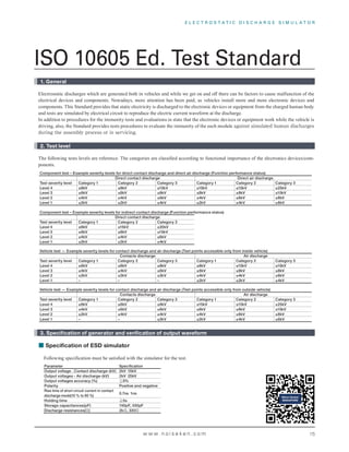
- 1. E L E C T R O S T A T I C D I S C H A R G E S I M U L A T O R w w w. n o i s e k e n . c o m 1. General Electrostatic discharges which are generated both in vehicles and while we get on and o there can be factors to cause malfunction of the HOHFWULFDO GH LFHV DQG FRPSRQHQWV 1R DGD V PRUH DWWHQWLRQ DV EHHQ SDLG DV H LFOHV LQVWDOO PRUH DQG PRUH HOHFWURQLF GH LFHV DQG FRPSRQHQWV LV 6WDQGDUG SUR LGHV W DW VWDWLF HOHFWULFLW LV GLVF DU HG WR W H HOHFWURQLF GH LFHV RU HT LSPHQW IURP W H F DU HG PDQ ERG DQG WHVWV DUH VLP ODWHG E HOHFWULFDO FLUF LW WR UHSURG FH W H HOHFWULF F UUHQW D HIRUP DW W H GLVF DU H ,Q DGGLWLRQ WR SURFHG UHV IRU W H LPP QLW WHVWV DQG H DO DWLRQV LQ VWDWH W DW W H HOHFWURQLF GH LFHV RU HT LSPHQW RUN LOH W H H LFOH LV GUL LQ DOVR W H 6WDQGDUG SUR LGHV WHVWV SURFHG UHV WR H DO DWH W H LPP QLW RI W H HDF PRG OH 2. Test level The following tests levels are reference. The categories are classi ed according to functional importance of the electronics devices/com SRQHQWV Component test – Example severity levels for direct contact discharge and direct air discharge (Function performance status) Direct contact discharge Direct air discharge. Test severity level Category 1 Category 2 Category 3 Category 1 Category 2 Category 3 Level 4 ±8kV ±8kV ±15kV ±15kV ±15kV ±25kV Level 3 ±6kV ±8kV ±8kV ±8kV ±8kV ±15kV Level 2 ±4kV ±4kV ±6kV ±4kV ±6kV ±8kV Level 1 ±2kV ±2kV ±4kV ±2kV ±4kV ±6kV Component test – Example severity levels for indirect contact discharge (Function performance status) Direct contact discharge Test severity level Category 1 Category 2 Category 3 Level 4 ±8kV ±15kV ±20kV Level 3 ±6kV ±8kV ±15kV Level 2 ±4kV ±4kV ±8kV Level 1 ±2kV ±2kV ±4kV Vehicle test — Example severity levels for contact discharge and air discharge (Test points accessible only from inside vehicle) Contacts discharge Air discharge Test severity level Category 1 Category 2 Category 3 Category 1 Category 2 Category 3 Level 4 ±6kV ±8kV ±8kV ±8kV ±15kV ±15kV Level 3 ±4kV ±4kV ±6kV ±6kV ±8kV ±8kV Level 2 ±2kV ±2kV ±2kV ±4kV ±4kV ±6kV Level 1 – – – ±2kV ±2kV ±4kV Vehicle test — Example severity levels for contact discharge and air discharge (Test points accessible only from outside vehicle) Contacts discharge Air discharge Test severity level Category 1 Category 2 Category 3 Category 1 Category 2 Category 3 Level 4 ±6kV ±8kV ±8kV ±15kV ±15kV ±25kV Level 3 ±4kV ±6kV ±6kV ±8kV ±8kV ±15kV Level 2 ±2kV ±4kV ±4kV ±4kV ±6kV ±8kV Level 1 – – ±2kV ±2kV ±4kV ±6kV 3. Specification of generator and verification of output waveform Following speci cation must be satis ed with the simulator for the test. Parameter Specification Output voltage . Contact discharge-(kV) 2kV 15kV Output voltages - Air discharge-(kV) 2kV 25kV Output voltages accuracy (%) 5% Polarity Positive and negative Rise time of short circuit current in contact discharge mode(10 % to 90 %) 0.7ns 1ns Holding time 5s Storage capacitances(pF) 150pF, 330pF Discharge resistances( ) 2k , 330 Specification of ESD simulator ISO 10605 Ed. Test Standard
- 2. w w w. n o i s e k e n . c o m Following discharges characteristics should be veri ed. Contact discharge mode current specifications Typical capacitance / resistance values Peak current / charge voltage Current at T1 / Charge voltage Current at T2 / Charge voltage 150pF/330 2A/kV ±30% (t1=30ns) 1A/kV ±30% (t2=60ns) 330pF/330 2A/kV ±30% (t1=65ns) 1A/kV ±30% (t2=130ns) 150pF/2k 0.275A/kV±30% (t1=180ns) 0.15A/kV±50% (t2=360ns) 330pF/2k 0.275A/kV±30% (t1=400ns) 0.15A/kV±50% (t2=800ns) 3.75A/kV ±10% 3.75A/kV +30% -0% The waveform shall be veri ed with an oscilloscope whose bandwidth is 1GHz or more in a Faraday cage or with a 1.2m x 1.2m metallic board mounting an ESD current target in the center of the cage or the board. The discharge electrode (Discharge tip of the gun) shall be WR F HG RQWR W H WDU HW DQG W H GLVF DU H PRGH V DOO EH VHW DW W H FRQWDFW GLVF DU H PRGH H GLVF DU H UHW UQ FDEOH V DOO EH W UQHG S W H FHQWHU RI W H OHQ W DQG FRQQHFWHG WR HUWLFDOO P QGHU W H WDU HW RQ V UIDFH RI W H DUDGD FD H RU ERDUG Verification of output current waveform 0 140 120 100 80 60 40 20 Y X 0 20 15 10 5 0 0 20 Y X 15 10 5 200 100 300 500 400 600 800 900 700 Discharge resistance 330 (at 5kV) Discharge resistance 330 (at 5kV) Calibration of target Adaptor for calibrating ESD current target (Model:06-00068A) Figure of attaching ESD current target and the calibration adaptor (Left : Target Right : Adaptor) ESD simulator Main unit 1200mm 1200mm Insertion of 20dB attenuator is recommended for protecting the oscilloscope Faraday cage Appropriate depth for the scope being used >0.6m from the center of the target to each side 0.6m form center of the current target to the each side Coaxial cable connecting as short as possible The discharge return cable should be connected vertically 0.5m under the current target and pulled up right backward Filter Connected point of the discharge gun return cable Discharge gun Fix the discharge gun with optional probe stand (03-00061B) or the substitute. * Never hold with hand 0.5m Faraday cage of Board to fix the target Discharge gun Oscilloscope 20dB attenuator 6dB Attenuator Conversion connector (SMA – BNC) ESD current target 06-00067A Coaxial cable Connecting method of ESD target Conical tip is used for the discharge 12-00007A (Standard equipped) 50Ω coaxial adaptor line Coaxial cable Coaxial cable Input port Output port Network Analyzer a : Calibration points with networks analyzer Testing Summary according to ISO 10605 Ed.2 Standard
- 3. E L E C T R O S T A T I C D I S C H A R G E S I M U L A T O R w w w. n o i s e k e n . c o m For testing powered DUT immunity to indirect ESD 4. Test setup and test procedure Capacitance shall be selected to 150 pF (In case for components accessible from outside vehicle) or 330 pF (In case for components accessible from inside vehicle) and resistance shall be 330 . The test level shall be two or more. At least 3 discharges shall be applied both to the positive and negative polarities with the interval not less than 1s. The time intervals between successive single discharges in the indirect discharge shall be longer than 50 ms and the number of the test shall be >50 times. In the contact discharge, it shall be done to wherever human finger may touch. In the air discharge, the speed of approach should be between 0.1 m/s and 0.5 m/s and the discharge tip is held per- pendicular to the surface of the DUT when possible; if not possible, an angle of at least 45° to the surface of the DUT is preferred. Insulating blocks shall be used for DUT which is not grounded to the chassis directly. For testing powered DUT immunity to direct ESD - Contact discharge and air discharge DUT ESD Generator Discharge gun Battery Periphery Isolating support Isolating support (If required) HCP Wooden (non-conductive) table Insulating block Ground reference plane Ground point Ground connection DUT ESD Generator Discharge gun Battery Periphery Isolating support Isolating support (If required) HCP Wooden (non-conductive) table Insulating block Insulating block Connectable to either HCP or GRP Ground reference plane Ground point Ground connection Testing Summary according to ISO 10605 Ed.2 Standard
- 4. w w w. n o i s e k e n . c o m For testing (unpowered) packaging and handling ESD sensitivity Vehicle test – Internal and external points Capacitance shall be selected to 150 pF (Although the resistance value is not provided, it is recommended to per- form the tests supposing both resistance when the DUT may be directly accessible by human body (2k ) and it may be accessible by a metal object a human hold (330 )) The test level shall be two or more. At least 3 discharges shall be applied both to the positive and negative polarities with the interval not less than 1s. In the contact discharge, it shall be done to wherever human finger may touch. Charge build-up should be eliminated by briefly connecting a bleeder wire with high resistance (>1M ) after the discharge and the DUT shall be turned on. Afterwards, normal operation of it shall be confirmed. Choose a generator capacitance of 330pF for areas that can easily be accessed only from the inside of the vehicle and resistance of 330 or 2 k Choose a capacitance of 150 pF for points that can easily be touched only from the outside of the vehicle and resis- tance of 330 or 2 k . The ESD generator ground shall be connected to chassis like the seat-rail in case of the interior test or connected to a metallic plate under the wheel closest to the application point in case of the exterior test. Both the contact discharge and air discharge shall be done both for the internal and external. Internal test External test DUT Discharge gun ESD Generator Dissipative mat, if required HCP (In this case, Ground reference plane) Wooden (non-conductive) table Ground point Ground point Ground connection Testing Summary according to ISO 10605 Ed.2 Standard
- 5. E L E C T R O S T A T I C D I S C H A R G E S I M U L A T O R w w w. n o i s e k e n . c o m Optional test set-up and procedure for electronic modules (powered-up test) – Direct and indirect discharge ESD G e ne rator Di sch arge gun Di sch arge gun HCP I nsul ati ng bl ock Batte ry Arti f i ci alne tw ork Pe ri ph e ry W oode n (non-conducti ve ) tabl e Fi e l d coupl i ng stri p DU T Notes: This test set-up is quoted from ISO10605 ed2.0 (2008) Standard. Please go through the Standard if the more details are required. Testing Summary according to ISO 10605 Ed.2 Standard
- 6. 2020-3K Authorized representative International Sales & Marketing Section 1-4-4 Chiyoda, Chuo-ku, Sagamihara City, Kanagawa Pref. 252-0237 Japan TEL: +81-(0)42-712-2051 FAX: +81-(0)42-712-2050 E-mail : sales@noiseken.com http://www.noiseken.com