SlideShare a Scribd company logo
1 of 11
Download to read offline
AN OVERALL DESCRIPTION OF FINITE ELEMENT CONTACT
ANALYSIS PROCEDURES (not underlying theory) USING ANSYS
AND APPLICATION ON A FULLASSEMBLY: A SAMPLE
GEARBOX (with an additional Appendix chapter on the structural
analysis of the composite, carbon-epoxy, sump, using
Patran-NASTRAN-ANSYS, ANSYS-only, and CLPT, Classical
Laminated Plate Theory, analysis procedures.) Author: Michael P. Siener
(not-yet-complete)
Special Topics (in Finite Element Analysis)
MECH 9021 , section 004
call number: 311557
Professor:
Yijun Liu, PhD
Professor; Director of CAE Research Lab
Mechanical Engineering
PO Box 210072
University of Cincinnati
Cincinnati, Ohio 45221-0072, USA
Tel: 1 (513) 556-4607
E-mail: Yijun.Liu@uc.edu
Web: www.yijunliu.com
Student:
Michael P. Siener
(experience in aircraft design, wind energy, high school teaching in Africa—Peace Corps)
9255 Sagemeadow Drive
Cincinnati. Ohio, 45251
Tel: (513)384-8971
mikesiener@yahoo.com
AN OVERALL DESCRIPTION OF FINITE ELEMENT CONTACT ANALYSIS
PROCEDURES (not underlying theory) USING ANSYS AND APPLICATION ON A
FULLASSEMBLY: A SAMPLE GEARBOX (with an additional Appendix chapter on
the structural analysis of the composite (carbon-epoxy) sump, using
Patran-NASTRAN-ANSYS, and ANSYS-only, CLPT analysis procedures.)
Author: Michael P. Siener
1.0 Background
The finite element method has been used for analyzing complex structures, and complex solid
mechanics problems for several decades. The use of the method for simulating a given body, made of a
given material under many varieties of boundary conditions in the engineering design process is not a
new practice as of this year of 2015.
From R. Courant's 'Variational methods for the solution of problems of equilibrium and vibrations', in
1942, J.H. Argyris, 'Energy theorems of structural analysis' in 1954, Clough and Martin et al, in the
1950s and early 1960s to O.C. Zienkiewicz in the 1960s to the 1990s … and many other brilliant
people developing and combining aspects of Mathematics and Physics to allow these to be adapted for
discrete analysis methods in-order that physical phenomena can be simulated; this general body of
work has continued to grow for some time.
Discrete methods of analysis where a structure or a medium is broken into smaller pieces and using the
power of a computer to calculate the behavior of each, utilizing already established laws of physics and
then providing the computer-programming to organize and assemble the effects of each piece on the
larger model, this overall method is used for simulating many physical aspects of nature. Among
others and in addition to solid mechanics, other analysis types include fluid mechanics, thermal
analysis, electro-magnetics, coupled-physics analysis including acoustics, crash dynamics/ crash
deformation and failure-from-impulse-loads, fluid-structure interaction, thermal-structural,... and more.
In solid mechanics the finite element method has gone from the hands of the developers of the method
to the users of the method and cross talk between developers and users has allowed it to be adapted to
solve a large variety of problems. Back to the mechanics of solids, in more recent years the idea of the
simulation of the contact of two or more deformable bodies has been seen as important. There are
technical papers from the 1970s and 1980s (Two examples: e.g.1: Finite Element Analysis of Contact
Problems, by Leonard R. Herrmann, M.ASCE, Prof. of Civ. Engrg., Univ. of California, Davis, Calif.
1978); (e.g. 2: 'A perturbed Lagrangian formulation for the finite element solution of contact
problems', Juan C. Simo, Peter Wriggers, Robert L. Taylor, 1985)(The “seminality” of these contact
papers may not be comparable with the founders of FEA theory such as Courant, Clough/Martin, and
Zeinkiewicz. These are the papers I was able to find and do not represent an exhaustive background
search of the work done. I do not know if these papers provide the underlying theory for contact
analysis implemented in programs such as ANSYS and Abaqus.)
The newer work in contact analysis theory reaches beyond but still uses some of the ideas of Heinrich
Hertz from 1882-- Hertz who solved the specific problem of contact between two elastic bodies with
curved surfaces, sometimes called Hertzian contact. The solid mechanics boundary condition of
contact is generally handled as an elastic problem. Elastic but not linear. That is, linear material
behavior is observed but not linear geometric behavior. Most meaningful contact analyses have-had to
address the inherent nonlinearities introduced by the geometrical behavior such as the change of
bearing area as load changes, and friction within two contacting or gapping surfaces. As far as
inelastic-material contact, that is being addressed also. Analysts are running simulations of forming
operations such as forging and other methods of work hardening and deformation processes. This
paper does not address nonlinear-material-behavior contact analysis, but there is no avoiding the
nonlinear geometric behavior inherent in the Physics of every contact boundary condition.
It has been recognized in more recent years since Hertz that treating a mechanical or structural
assembly of components as one monolithic part, as if all the components were “welded”, or machined
out of one block of material, creates significant errors in the solution of a solid mechanics problem that
might cause the analyst to miss critical stresses, or critical deformations or slippages within an
assembly, that must be addressed in the design of an overall structure/assembly/mechanism, for proper
operation and/or adequate fatigue life to be attained in the final design. For example, it is easy to see
that the contact stress caused by imposing a weight on the end of a cantilever beam is generally not the
critical stress in the structure, the stress at the root of the beam, the bending stress, is generally
considered the critical stress in the structure of a single simple cantilever beam. But what if the
cantilever beam is bolted or riveted to the attaching structure rather than welded to its attaching
structure? Even within a weld, sometimes the simplifying assumption of a regular exact radius and
looking at the “throat” of the weld (aka Shigley), instead of looking at the discrete beads and weldment
material, can be a mistake. It is important that at the very least all suspected primary modes of failure
in a comprehensive structural analysis be explored. And many times the success or failure of an
analysis is attached to what scale the analyst chooses for analysis. Additional computer power has
allowed the analyst to model more exactly, in greater detail, a given structure. Perhaps eventually we
will have the power to analyze even at the atomic level. But is that really necessary? The answer to
that lies in the answer to the question, what information is needed?-- What are we looking for?
So, what if the mode-of-failure of a cantilever beam is shearing or tensile-failure of the bolts
with-which it is attached? In the case of this one cantilever beam the reaction bolt loads could be
assessed and a check made to see if those loads are within the allowable loads for the bolts in-question.
That would probably be enough and no more analysis required. It is assumed that in the case of a
simple cantilever beam the attaching bolts would be few, the loads are not eccentric and a given
scenario of load sharing could be assumed if not outright calculated, so-as an accurate load in each
given bolt could be obtained and compared with what load is allowable.
But what about eccentric loads? What about bolted connections which include many bolts with
interacting preloads? (i.e.,If a preload on a given bolt is relaxed, either through wear or some other load
redistributing mechanism, the preload on neighboring bolts typically change as-well.) In the case of
engines and gear boxes, what about the bolts that hold heads to engine blocks, bolts that hold engine
blocks to vehicle frames, and bolts that hold housings together? And what about the (usually)
lower-strength, brittle castings (cast iron, cast aluminum or cast magnesium which have much lower
strengths and are much more brittle than their wrought forms) held together by, and impinged-on by
high strength bolts? What about press fits? What about bearing loads? All of these cases of contact
need a better approximation as-to how their attachments are made than only the assumption of a
“welded” attachment. The many cases of failure at these locations throughout the history of structural
engineering indicates this is true.
Oversimplification of a structure in the process of analyzing it, so as to eliminate the mode in which it
would fail is a mistake. And structures many times fail at a joint, whether bolted, riveted, press-fit,
bonded, and welded.
Aircraft, both airframe and propulsion systems, and wind turbine technology, I have some experience
with both. Both sectors have a large need to generate simulation-models of assemblies of components
and structures which have a more realistic representation of joining conditions than just the assumption
of “welded”.
Consequently contact analysis utilizing the finite element method which is already performed on some
components is apparently even more needed as an important tool in solving some of these problems on
mechanisms, machines and engines/transmission-systems.
This project is an exercise in practicing the application of contact analysis. By creating an assembly of
bolted-joints, press-fits, and a shaft-into-bearing load-application-points in an engine-gearbox-like
assembly, I hope to recreate what might be typical of such analysis and explore some of the problems
of doing this type of analysis with the Finite Element Analysis software package, ANSYS.
Care must be taken in creating this sample-model as far as size. While the rest of us have taken for
granted the overwhelming power of today's PCs for doing word processing, spreadsheet-ing,
powerpoint-ing, and linear finite element analysis, analysts running finite element models reflecting
nonlinear contact conditions are still challenged with having enough computer power to do the job
adequately. A million dof (degrees of freedom) linear FEA problem can be solved in less than minutes
on a relatively powerful desktop PC. A million dof (degrees of freedom) model simulating nonlinear
contact conditions with just a few contact surfaces can take hours. (I ran a simple 2-D gear (spur-gear)
contact problem not too long ago and that problem took over a week to solve, or converge to a
solution, on a Dell Precision T3500.) The Dell T3610 desktop computer available to a student at the
University of Cincinnati in the year 2015, while considered a solid engineering workstation, is still
limited by how large of a problem it can solve in a “practical” amount of time. This was the main
constraint which dictated the decision to “design” a nonfunctional gearbox rather than a functional one.
There are already enough contact surfaces, press fits, and bolts in this nonfunctional gearbox. Adding
the functionality of three dimensional meshing gear teeth, and modeling the contact conditions between
those teeth adequately would have been too much for the computer resources available. Perhaps a
follow-on project could take up that task.
But this project is not about solving the largest most complex contact/assembly problem. It is about
solving a contact/assembly problem which can be encountered today and the steps needed in-order to
do that. Further one can spend an infinite amount of time ( money and effort) solving the wrong
problem and generating nice colors. But unless the critical, relevant characteristics of a structural
problem are represented and analyzed, so much time (money and effort) can be wasted.
I say this but unfortunately I have wasted a lot of time myself doing “the wrong” analysis. The finite
element method itself is an approximation. Sometimes it is necessary to do the “wrong” analysis
before one can do the “right” analysis. Even if an analyst can create a “good” model as a “first cut” in
a given model simulation, it is almost always possible to create a “better” model. This paper is not
meant to debate the philosophy of FEA. The pertinent question is whether that better model will
uncover any critical aspects of the assembly simulated.
This project does not go deeply into the theory of contact analysis, there are books and technical papers
that already do that. ('Concepts and Applications of Finite Element Analysis', fourth edition, by Cook,
Malkus, Plesha, Witt, seems to be particularly good at handling the explanation of the theoretical
background of the general finite element method and does have a section in chapter 17 on gap and
contact analysis.)
Nor is this project an exercise in designing transmission systems. There are many wonderfully-creative
examples of transmission systems and drive train development and that is a subject that is handled as a
separate effort when designing a drive system.
Nor does this paper concern itself with load-spectrum/block-load design. Fatigue analysis typically
includes some aspect of the Palmgren-Miner rule for useful life estimation. How that is done from
sector to sector (if not company to company)is interesting but not a subject of this paper. The loads I
apply on this model will be representative of what wold be imposed on a gearbox of like size and I will
make no attempt to build a spectrum of load conditions in order to calculate a fatigue life.
Even in the specialized area of contact analysis, this paper will not cover the many types of ways that
contact simulation is achieved nor an exhaustive study of the different types of contact elements that
ANSYS has created to be used in different analysis cases such as 2-D or node-to-node contact. I have
used several of those elements. The ones I used seem to work well. For a more comprehensive
description of ANSYS contact analysis, download a copy of the contact guide at: (Thank you so much
for making it available , UC Davis.)
orange.engr.ucdavis.edu/Documentation12.1/121/ans_ctec.pdf
I will concentrate on surface-to-surface contact using the ANSYS CONTA174 and the TARGE170
elements for the contact and target surfaces respectively. I will say more about these elements later but
for now, I anticipate using SOLID186 and SOLID187 elements throughout the model which are higher
order, mid-side node (much more forgiving of poor-shape than liner non-mid-side node linear elements,
such as the SOLID45 element.) quadratic elements. The CONTA174 element also has mid-side nodes
and must be used when the underlying solid element also have mid-side nodes. The same is not true of
the TARGE170, as this is a four node quadrilateral element to be used even when the underlying
elements are higher order.
Here is a Preliminary Outline of this project:
1. Contact analysis steps
2. Contact parameters
3. Solver selection
3. Load stepping
3. What results of contact analysis can be used for and what they cannot be used for. (Not wear. Not
use of the bearing strength number from Mil-hnbk-5.)
4. Use of results in
a. static strength
b. fatigue analysis
c. crack growth analysis
5. The use of modularity.
6. Typical model
7. Details of the specific typical model used for this project.
2.0 Procedure
2.1 Overall Contact Analysis Steps The understanding of how to organize for a contact
analysis comes more and more into focus the more times that an analyst performs such an
analysis. Since we are simulating the contact between two surfaces, generally we need at least
two bodies. Not always as a single body could bend around and come back and make contact
with itself, which is also “simulatable”. But let us exclude that possibility for this paper for the
sake of concision.
In the majority of cases the analyst will be importing geometry from some CAD tool into some
finite element program. There are many CAD programs and there are many FEA (finite
element analysis) programs. In this case I will be importing geometry I have generated in the
CAD program SolidWorks into ANSYS Workbench. In ANSYS Workbench I will xxx and then
output a file from ANSYS Workbench into ANSYS APDL (Classic) where I can have more
control over several important aspects of the finite element model including meshing and
running the solution.
Then I will postprocess and examine the results of the solve process inside of ANSYS APDL
and discuss the meaning of those results.
2.2 Creating the CAD Geometry This work is generally not the work of the finite element
analyst at least how it is organized these days in the larger design houses with larger
corporations. More and more and with smaller companies with fewer employees one person
might be doing everything from design to CAD to any pertinent analysis whether hand analysis
or computer analysis including simulation: And so who performs what aspect of the design
work varies.
But generally the part designer has an idea what (s)he wants as far as form and function and
how it interfaces with the rest of the assembly, and that drives the CAD geometry. At this point
very little if any accommodation is made for the finite element model. And rightly so, the
designer generally has a challenging-enough task just coming up with a design that will work
for the purpose intended. It is up to the analyst to accommodate the analysis of any geometry
generated. (Including “defeaturing”, a step in the model preparation where features not deemed
important to the analysis of the part (,but which would require longer computer run times since
they need more elements to represent) are removed.
in general the CAD geometry is handled on two levels. One at the part level, and two at the
assembly level (one could also argue more levels when talking about “sub-assemblies”). A full
assembly file is maintained and it contains the “official” design of the system which is being
designed: This file contains the total current CAD geometry of the “system” (whether it be a
transmission system, an engine system, an airframe system (not usually called-that), a
hydraulic/pneumatic/pneudraulic system,...).
Then part files are also maintained, though not independently of the assembly file. An official
part file is typically “tied” to that same part represented in the assembly file so that changes
cannot be made which are not reflected in the assembly file. Then those files are maintained by
including a “checkout process” implemented by the engineering group doing the work so that
conflicting work cannot proceed. Such as two engineers working on the same part at the same
time, with one engineer making changes that the other engineer is not aware of. That is the
general procedure followed by a design house, let me not go into any more depth about that.
There are as many ways to implement this check-process as there are engineering companies
who do full systems design.
But as far as the model chosen for this paper, I pursued a design that requires the contact
analysis that we are interested in this paper.: Three planar contact regions., two(overt)
press-fits (also contact areas but these are cylindrical), twelve bolted connections with their own
contact areas (and imposed “press-fits” through use of ANSYS pretension elements), three
bearing surfaces, in a gearbox/engine-like assembly. The particular design does not represent
any real gearbox design that would be considered. I was limited on what I could do with a
small desktop computer so I included only one shaft with no real gear-on-gear contact.
Knowing that the ANSYS pretension elements introduce significant nonlinearity to the final
solution, I included only large bolts at only the corners of the bolted connections rather than a
greater number of smaller fasteners that would give a more continuous bolted joint. (Which
would be stronger and in the case of the sump, would inhibit any oil leakage.)
I'm not an experienced gearbox designer (I've done analysis of already-designed or
in-the-process-of-being-designed gearboxes, and in-that-way contributed to final designs or
modifications, but not actually laid out an initial design or a drive-train.) I've included ribs,
emulating what I have seen, that the load from the loaded shaft must be conducted to the
stronger-more-rigid structure of the gear box housing. So load in this casting is directed to the
heavy corner bolts of the gear box and I have thickened it up at those locations in the corners.
Then I have included a sump made of thinner material, in this case a layup of unidirectional
plies of Hexel xxx Carbon-Epoxy. I have seen carbon fiber sumps and have included this one
here so that I could practice my use of orthotropic composite analysis in ANSYS.
Fig. 1- Solidworks model of gearbox. Exploded view shown.
Fig. 2- Workbench model of gearbox after importing parasolids model from Solidworks.
Fig. 3- Workbench model showing.preliminary maximum principal strain results from one proof load
case.
Fig. 4- ANSYS Classic model showing .same results as the image from the (previous image)
Workbench model to show the viability of inputting file from Workbench into Classic..
<more later>

More Related Content

Similar to d_9_special-topics-project_FEA-of-full-assemblies

Lecture failure criteria
Lecture   failure criteriaLecture   failure criteria
Lecture failure criteriaHamdani Nurdin
 
A critical comparison of shear tests for adhesive joints.pdf
A critical comparison of shear tests for adhesive joints.pdfA critical comparison of shear tests for adhesive joints.pdf
A critical comparison of shear tests for adhesive joints.pdfssuser9f67f31
 
Nasa the merging of fatigue and fracture mechanics concepts
Nasa   the merging of fatigue and fracture mechanics conceptsNasa   the merging of fatigue and fracture mechanics concepts
Nasa the merging of fatigue and fracture mechanics conceptsTarelli Riccardo
 
colorado.pdf
colorado.pdfcolorado.pdf
colorado.pdfbereketg4
 
Unit 1 notes-final
Unit 1 notes-finalUnit 1 notes-final
Unit 1 notes-finaljagadish108
 
Paper id 71201964
Paper id 71201964Paper id 71201964
Paper id 71201964IJRAT
 
Generalised_formulation_of_laminate_theory_using_beam_fe_for_delaminated_comp...
Generalised_formulation_of_laminate_theory_using_beam_fe_for_delaminated_comp...Generalised_formulation_of_laminate_theory_using_beam_fe_for_delaminated_comp...
Generalised_formulation_of_laminate_theory_using_beam_fe_for_delaminated_comp...Shree Bineet Kumar Kavi
 
A Review on Finite Element Analysis of Beam to Column Endplate Bolted Connection
A Review on Finite Element Analysis of Beam to Column Endplate Bolted ConnectionA Review on Finite Element Analysis of Beam to Column Endplate Bolted Connection
A Review on Finite Element Analysis of Beam to Column Endplate Bolted ConnectionIOSR Journals
 
THREE-DIMENSIONAL STUDY FOR THE RELATIVE POSITIONING OF MECHANICAL ELEMENTS I...
THREE-DIMENSIONAL STUDY FOR THE RELATIVE POSITIONING OF MECHANICAL ELEMENTS I...THREE-DIMENSIONAL STUDY FOR THE RELATIVE POSITIONING OF MECHANICAL ELEMENTS I...
THREE-DIMENSIONAL STUDY FOR THE RELATIVE POSITIONING OF MECHANICAL ELEMENTS I...meijjournal
 
TD-15-035_FINAL_Wheels_Maintenance
TD-15-035_FINAL_Wheels_MaintenanceTD-15-035_FINAL_Wheels_Maintenance
TD-15-035_FINAL_Wheels_MaintenanceMaysam Kiani
 
Advanced Topics in Offshore Wind Turbines Design
Advanced Topics in Offshore Wind Turbines DesignAdvanced Topics in Offshore Wind Turbines Design
Advanced Topics in Offshore Wind Turbines DesignFranco Bontempi
 
Analysis and Design of RECTANGULAR SEWERAGE TANK_2023.docx
Analysis and Design of RECTANGULAR SEWERAGE TANK_2023.docxAnalysis and Design of RECTANGULAR SEWERAGE TANK_2023.docx
Analysis and Design of RECTANGULAR SEWERAGE TANK_2023.docxAdnan Lazem
 
Studies on factors influencing the behavior of bolted flanged joints
Studies on factors influencing the behavior of bolted flanged jointsStudies on factors influencing the behavior of bolted flanged joints
Studies on factors influencing the behavior of bolted flanged jointseSAT Journals
 
REVIEW OF TRUE BENDING STRESS IN SPUR GEAR
REVIEW OF TRUE BENDING STRESS IN SPUR GEARREVIEW OF TRUE BENDING STRESS IN SPUR GEAR
REVIEW OF TRUE BENDING STRESS IN SPUR GEARIRJET Journal
 

Similar to d_9_special-topics-project_FEA-of-full-assemblies (20)

Lecture failure criteria
Lecture   failure criteriaLecture   failure criteria
Lecture failure criteria
 
ED7104 VAC_notes
ED7104 VAC_notesED7104 VAC_notes
ED7104 VAC_notes
 
Fem utkarsh
Fem utkarshFem utkarsh
Fem utkarsh
 
A critical comparison of shear tests for adhesive joints.pdf
A critical comparison of shear tests for adhesive joints.pdfA critical comparison of shear tests for adhesive joints.pdf
A critical comparison of shear tests for adhesive joints.pdf
 
Nasa the merging of fatigue and fracture mechanics concepts
Nasa   the merging of fatigue and fracture mechanics conceptsNasa   the merging of fatigue and fracture mechanics concepts
Nasa the merging of fatigue and fracture mechanics concepts
 
colorado.pdf
colorado.pdfcolorado.pdf
colorado.pdf
 
Unit 1 notes-final
Unit 1 notes-finalUnit 1 notes-final
Unit 1 notes-final
 
Paper id 71201964
Paper id 71201964Paper id 71201964
Paper id 71201964
 
Generalised_formulation_of_laminate_theory_using_beam_fe_for_delaminated_comp...
Generalised_formulation_of_laminate_theory_using_beam_fe_for_delaminated_comp...Generalised_formulation_of_laminate_theory_using_beam_fe_for_delaminated_comp...
Generalised_formulation_of_laminate_theory_using_beam_fe_for_delaminated_comp...
 
A Review on Finite Element Analysis of Beam to Column Endplate Bolted Connection
A Review on Finite Element Analysis of Beam to Column Endplate Bolted ConnectionA Review on Finite Element Analysis of Beam to Column Endplate Bolted Connection
A Review on Finite Element Analysis of Beam to Column Endplate Bolted Connection
 
ED7012 SE_notes
ED7012 SE_notesED7012 SE_notes
ED7012 SE_notes
 
THREE-DIMENSIONAL STUDY FOR THE RELATIVE POSITIONING OF MECHANICAL ELEMENTS I...
THREE-DIMENSIONAL STUDY FOR THE RELATIVE POSITIONING OF MECHANICAL ELEMENTS I...THREE-DIMENSIONAL STUDY FOR THE RELATIVE POSITIONING OF MECHANICAL ELEMENTS I...
THREE-DIMENSIONAL STUDY FOR THE RELATIVE POSITIONING OF MECHANICAL ELEMENTS I...
 
THREE-DIMENSIONAL STUDY FOR THE RELATIVE POSITIONING OF MECHANICAL ELEMENTS I...
THREE-DIMENSIONAL STUDY FOR THE RELATIVE POSITIONING OF MECHANICAL ELEMENTS I...THREE-DIMENSIONAL STUDY FOR THE RELATIVE POSITIONING OF MECHANICAL ELEMENTS I...
THREE-DIMENSIONAL STUDY FOR THE RELATIVE POSITIONING OF MECHANICAL ELEMENTS I...
 
Eng design 7
Eng design 7Eng design 7
Eng design 7
 
TD-15-035_FINAL_Wheels_Maintenance
TD-15-035_FINAL_Wheels_MaintenanceTD-15-035_FINAL_Wheels_Maintenance
TD-15-035_FINAL_Wheels_Maintenance
 
Fem presentation
Fem presentationFem presentation
Fem presentation
 
Advanced Topics in Offshore Wind Turbines Design
Advanced Topics in Offshore Wind Turbines DesignAdvanced Topics in Offshore Wind Turbines Design
Advanced Topics in Offshore Wind Turbines Design
 
Analysis and Design of RECTANGULAR SEWERAGE TANK_2023.docx
Analysis and Design of RECTANGULAR SEWERAGE TANK_2023.docxAnalysis and Design of RECTANGULAR SEWERAGE TANK_2023.docx
Analysis and Design of RECTANGULAR SEWERAGE TANK_2023.docx
 
Studies on factors influencing the behavior of bolted flanged joints
Studies on factors influencing the behavior of bolted flanged jointsStudies on factors influencing the behavior of bolted flanged joints
Studies on factors influencing the behavior of bolted flanged joints
 
REVIEW OF TRUE BENDING STRESS IN SPUR GEAR
REVIEW OF TRUE BENDING STRESS IN SPUR GEARREVIEW OF TRUE BENDING STRESS IN SPUR GEAR
REVIEW OF TRUE BENDING STRESS IN SPUR GEAR
 

d_9_special-topics-project_FEA-of-full-assemblies

  • 1. AN OVERALL DESCRIPTION OF FINITE ELEMENT CONTACT ANALYSIS PROCEDURES (not underlying theory) USING ANSYS AND APPLICATION ON A FULLASSEMBLY: A SAMPLE GEARBOX (with an additional Appendix chapter on the structural analysis of the composite, carbon-epoxy, sump, using Patran-NASTRAN-ANSYS, ANSYS-only, and CLPT, Classical Laminated Plate Theory, analysis procedures.) Author: Michael P. Siener (not-yet-complete)
  • 2. Special Topics (in Finite Element Analysis) MECH 9021 , section 004 call number: 311557 Professor: Yijun Liu, PhD Professor; Director of CAE Research Lab Mechanical Engineering PO Box 210072 University of Cincinnati Cincinnati, Ohio 45221-0072, USA Tel: 1 (513) 556-4607 E-mail: Yijun.Liu@uc.edu Web: www.yijunliu.com Student: Michael P. Siener (experience in aircraft design, wind energy, high school teaching in Africa—Peace Corps) 9255 Sagemeadow Drive Cincinnati. Ohio, 45251 Tel: (513)384-8971 mikesiener@yahoo.com
  • 3. AN OVERALL DESCRIPTION OF FINITE ELEMENT CONTACT ANALYSIS PROCEDURES (not underlying theory) USING ANSYS AND APPLICATION ON A FULLASSEMBLY: A SAMPLE GEARBOX (with an additional Appendix chapter on the structural analysis of the composite (carbon-epoxy) sump, using Patran-NASTRAN-ANSYS, and ANSYS-only, CLPT analysis procedures.) Author: Michael P. Siener 1.0 Background The finite element method has been used for analyzing complex structures, and complex solid mechanics problems for several decades. The use of the method for simulating a given body, made of a given material under many varieties of boundary conditions in the engineering design process is not a new practice as of this year of 2015. From R. Courant's 'Variational methods for the solution of problems of equilibrium and vibrations', in 1942, J.H. Argyris, 'Energy theorems of structural analysis' in 1954, Clough and Martin et al, in the 1950s and early 1960s to O.C. Zienkiewicz in the 1960s to the 1990s … and many other brilliant people developing and combining aspects of Mathematics and Physics to allow these to be adapted for discrete analysis methods in-order that physical phenomena can be simulated; this general body of work has continued to grow for some time. Discrete methods of analysis where a structure or a medium is broken into smaller pieces and using the power of a computer to calculate the behavior of each, utilizing already established laws of physics and then providing the computer-programming to organize and assemble the effects of each piece on the larger model, this overall method is used for simulating many physical aspects of nature. Among others and in addition to solid mechanics, other analysis types include fluid mechanics, thermal analysis, electro-magnetics, coupled-physics analysis including acoustics, crash dynamics/ crash deformation and failure-from-impulse-loads, fluid-structure interaction, thermal-structural,... and more. In solid mechanics the finite element method has gone from the hands of the developers of the method to the users of the method and cross talk between developers and users has allowed it to be adapted to solve a large variety of problems. Back to the mechanics of solids, in more recent years the idea of the simulation of the contact of two or more deformable bodies has been seen as important. There are technical papers from the 1970s and 1980s (Two examples: e.g.1: Finite Element Analysis of Contact Problems, by Leonard R. Herrmann, M.ASCE, Prof. of Civ. Engrg., Univ. of California, Davis, Calif. 1978); (e.g. 2: 'A perturbed Lagrangian formulation for the finite element solution of contact problems', Juan C. Simo, Peter Wriggers, Robert L. Taylor, 1985)(The “seminality” of these contact papers may not be comparable with the founders of FEA theory such as Courant, Clough/Martin, and Zeinkiewicz. These are the papers I was able to find and do not represent an exhaustive background search of the work done. I do not know if these papers provide the underlying theory for contact analysis implemented in programs such as ANSYS and Abaqus.) The newer work in contact analysis theory reaches beyond but still uses some of the ideas of Heinrich Hertz from 1882-- Hertz who solved the specific problem of contact between two elastic bodies with curved surfaces, sometimes called Hertzian contact. The solid mechanics boundary condition of contact is generally handled as an elastic problem. Elastic but not linear. That is, linear material behavior is observed but not linear geometric behavior. Most meaningful contact analyses have-had to
  • 4. address the inherent nonlinearities introduced by the geometrical behavior such as the change of bearing area as load changes, and friction within two contacting or gapping surfaces. As far as inelastic-material contact, that is being addressed also. Analysts are running simulations of forming operations such as forging and other methods of work hardening and deformation processes. This paper does not address nonlinear-material-behavior contact analysis, but there is no avoiding the nonlinear geometric behavior inherent in the Physics of every contact boundary condition. It has been recognized in more recent years since Hertz that treating a mechanical or structural assembly of components as one monolithic part, as if all the components were “welded”, or machined out of one block of material, creates significant errors in the solution of a solid mechanics problem that might cause the analyst to miss critical stresses, or critical deformations or slippages within an assembly, that must be addressed in the design of an overall structure/assembly/mechanism, for proper operation and/or adequate fatigue life to be attained in the final design. For example, it is easy to see that the contact stress caused by imposing a weight on the end of a cantilever beam is generally not the critical stress in the structure, the stress at the root of the beam, the bending stress, is generally considered the critical stress in the structure of a single simple cantilever beam. But what if the cantilever beam is bolted or riveted to the attaching structure rather than welded to its attaching structure? Even within a weld, sometimes the simplifying assumption of a regular exact radius and looking at the “throat” of the weld (aka Shigley), instead of looking at the discrete beads and weldment material, can be a mistake. It is important that at the very least all suspected primary modes of failure in a comprehensive structural analysis be explored. And many times the success or failure of an analysis is attached to what scale the analyst chooses for analysis. Additional computer power has allowed the analyst to model more exactly, in greater detail, a given structure. Perhaps eventually we will have the power to analyze even at the atomic level. But is that really necessary? The answer to that lies in the answer to the question, what information is needed?-- What are we looking for? So, what if the mode-of-failure of a cantilever beam is shearing or tensile-failure of the bolts with-which it is attached? In the case of this one cantilever beam the reaction bolt loads could be assessed and a check made to see if those loads are within the allowable loads for the bolts in-question. That would probably be enough and no more analysis required. It is assumed that in the case of a simple cantilever beam the attaching bolts would be few, the loads are not eccentric and a given scenario of load sharing could be assumed if not outright calculated, so-as an accurate load in each given bolt could be obtained and compared with what load is allowable. But what about eccentric loads? What about bolted connections which include many bolts with interacting preloads? (i.e.,If a preload on a given bolt is relaxed, either through wear or some other load redistributing mechanism, the preload on neighboring bolts typically change as-well.) In the case of engines and gear boxes, what about the bolts that hold heads to engine blocks, bolts that hold engine blocks to vehicle frames, and bolts that hold housings together? And what about the (usually) lower-strength, brittle castings (cast iron, cast aluminum or cast magnesium which have much lower strengths and are much more brittle than their wrought forms) held together by, and impinged-on by high strength bolts? What about press fits? What about bearing loads? All of these cases of contact need a better approximation as-to how their attachments are made than only the assumption of a “welded” attachment. The many cases of failure at these locations throughout the history of structural engineering indicates this is true. Oversimplification of a structure in the process of analyzing it, so as to eliminate the mode in which it would fail is a mistake. And structures many times fail at a joint, whether bolted, riveted, press-fit, bonded, and welded.
  • 5. Aircraft, both airframe and propulsion systems, and wind turbine technology, I have some experience with both. Both sectors have a large need to generate simulation-models of assemblies of components and structures which have a more realistic representation of joining conditions than just the assumption of “welded”. Consequently contact analysis utilizing the finite element method which is already performed on some components is apparently even more needed as an important tool in solving some of these problems on mechanisms, machines and engines/transmission-systems. This project is an exercise in practicing the application of contact analysis. By creating an assembly of bolted-joints, press-fits, and a shaft-into-bearing load-application-points in an engine-gearbox-like assembly, I hope to recreate what might be typical of such analysis and explore some of the problems of doing this type of analysis with the Finite Element Analysis software package, ANSYS. Care must be taken in creating this sample-model as far as size. While the rest of us have taken for granted the overwhelming power of today's PCs for doing word processing, spreadsheet-ing, powerpoint-ing, and linear finite element analysis, analysts running finite element models reflecting nonlinear contact conditions are still challenged with having enough computer power to do the job adequately. A million dof (degrees of freedom) linear FEA problem can be solved in less than minutes on a relatively powerful desktop PC. A million dof (degrees of freedom) model simulating nonlinear contact conditions with just a few contact surfaces can take hours. (I ran a simple 2-D gear (spur-gear) contact problem not too long ago and that problem took over a week to solve, or converge to a solution, on a Dell Precision T3500.) The Dell T3610 desktop computer available to a student at the University of Cincinnati in the year 2015, while considered a solid engineering workstation, is still limited by how large of a problem it can solve in a “practical” amount of time. This was the main constraint which dictated the decision to “design” a nonfunctional gearbox rather than a functional one. There are already enough contact surfaces, press fits, and bolts in this nonfunctional gearbox. Adding the functionality of three dimensional meshing gear teeth, and modeling the contact conditions between those teeth adequately would have been too much for the computer resources available. Perhaps a follow-on project could take up that task. But this project is not about solving the largest most complex contact/assembly problem. It is about solving a contact/assembly problem which can be encountered today and the steps needed in-order to do that. Further one can spend an infinite amount of time ( money and effort) solving the wrong problem and generating nice colors. But unless the critical, relevant characteristics of a structural problem are represented and analyzed, so much time (money and effort) can be wasted. I say this but unfortunately I have wasted a lot of time myself doing “the wrong” analysis. The finite element method itself is an approximation. Sometimes it is necessary to do the “wrong” analysis before one can do the “right” analysis. Even if an analyst can create a “good” model as a “first cut” in a given model simulation, it is almost always possible to create a “better” model. This paper is not meant to debate the philosophy of FEA. The pertinent question is whether that better model will uncover any critical aspects of the assembly simulated. This project does not go deeply into the theory of contact analysis, there are books and technical papers that already do that. ('Concepts and Applications of Finite Element Analysis', fourth edition, by Cook, Malkus, Plesha, Witt, seems to be particularly good at handling the explanation of the theoretical background of the general finite element method and does have a section in chapter 17 on gap and
  • 6. contact analysis.) Nor is this project an exercise in designing transmission systems. There are many wonderfully-creative examples of transmission systems and drive train development and that is a subject that is handled as a separate effort when designing a drive system. Nor does this paper concern itself with load-spectrum/block-load design. Fatigue analysis typically includes some aspect of the Palmgren-Miner rule for useful life estimation. How that is done from sector to sector (if not company to company)is interesting but not a subject of this paper. The loads I apply on this model will be representative of what wold be imposed on a gearbox of like size and I will make no attempt to build a spectrum of load conditions in order to calculate a fatigue life. Even in the specialized area of contact analysis, this paper will not cover the many types of ways that contact simulation is achieved nor an exhaustive study of the different types of contact elements that ANSYS has created to be used in different analysis cases such as 2-D or node-to-node contact. I have used several of those elements. The ones I used seem to work well. For a more comprehensive description of ANSYS contact analysis, download a copy of the contact guide at: (Thank you so much for making it available , UC Davis.) orange.engr.ucdavis.edu/Documentation12.1/121/ans_ctec.pdf I will concentrate on surface-to-surface contact using the ANSYS CONTA174 and the TARGE170 elements for the contact and target surfaces respectively. I will say more about these elements later but for now, I anticipate using SOLID186 and SOLID187 elements throughout the model which are higher order, mid-side node (much more forgiving of poor-shape than liner non-mid-side node linear elements, such as the SOLID45 element.) quadratic elements. The CONTA174 element also has mid-side nodes and must be used when the underlying solid element also have mid-side nodes. The same is not true of the TARGE170, as this is a four node quadrilateral element to be used even when the underlying elements are higher order. Here is a Preliminary Outline of this project: 1. Contact analysis steps 2. Contact parameters 3. Solver selection 3. Load stepping 3. What results of contact analysis can be used for and what they cannot be used for. (Not wear. Not use of the bearing strength number from Mil-hnbk-5.) 4. Use of results in a. static strength b. fatigue analysis c. crack growth analysis
  • 7. 5. The use of modularity. 6. Typical model 7. Details of the specific typical model used for this project. 2.0 Procedure 2.1 Overall Contact Analysis Steps The understanding of how to organize for a contact analysis comes more and more into focus the more times that an analyst performs such an analysis. Since we are simulating the contact between two surfaces, generally we need at least two bodies. Not always as a single body could bend around and come back and make contact with itself, which is also “simulatable”. But let us exclude that possibility for this paper for the sake of concision. In the majority of cases the analyst will be importing geometry from some CAD tool into some finite element program. There are many CAD programs and there are many FEA (finite element analysis) programs. In this case I will be importing geometry I have generated in the CAD program SolidWorks into ANSYS Workbench. In ANSYS Workbench I will xxx and then output a file from ANSYS Workbench into ANSYS APDL (Classic) where I can have more control over several important aspects of the finite element model including meshing and running the solution. Then I will postprocess and examine the results of the solve process inside of ANSYS APDL and discuss the meaning of those results. 2.2 Creating the CAD Geometry This work is generally not the work of the finite element analyst at least how it is organized these days in the larger design houses with larger corporations. More and more and with smaller companies with fewer employees one person might be doing everything from design to CAD to any pertinent analysis whether hand analysis or computer analysis including simulation: And so who performs what aspect of the design work varies. But generally the part designer has an idea what (s)he wants as far as form and function and how it interfaces with the rest of the assembly, and that drives the CAD geometry. At this point very little if any accommodation is made for the finite element model. And rightly so, the designer generally has a challenging-enough task just coming up with a design that will work for the purpose intended. It is up to the analyst to accommodate the analysis of any geometry generated. (Including “defeaturing”, a step in the model preparation where features not deemed important to the analysis of the part (,but which would require longer computer run times since they need more elements to represent) are removed. in general the CAD geometry is handled on two levels. One at the part level, and two at the assembly level (one could also argue more levels when talking about “sub-assemblies”). A full
  • 8. assembly file is maintained and it contains the “official” design of the system which is being designed: This file contains the total current CAD geometry of the “system” (whether it be a transmission system, an engine system, an airframe system (not usually called-that), a hydraulic/pneumatic/pneudraulic system,...). Then part files are also maintained, though not independently of the assembly file. An official part file is typically “tied” to that same part represented in the assembly file so that changes cannot be made which are not reflected in the assembly file. Then those files are maintained by including a “checkout process” implemented by the engineering group doing the work so that conflicting work cannot proceed. Such as two engineers working on the same part at the same time, with one engineer making changes that the other engineer is not aware of. That is the general procedure followed by a design house, let me not go into any more depth about that. There are as many ways to implement this check-process as there are engineering companies who do full systems design. But as far as the model chosen for this paper, I pursued a design that requires the contact analysis that we are interested in this paper.: Three planar contact regions., two(overt) press-fits (also contact areas but these are cylindrical), twelve bolted connections with their own contact areas (and imposed “press-fits” through use of ANSYS pretension elements), three bearing surfaces, in a gearbox/engine-like assembly. The particular design does not represent any real gearbox design that would be considered. I was limited on what I could do with a small desktop computer so I included only one shaft with no real gear-on-gear contact. Knowing that the ANSYS pretension elements introduce significant nonlinearity to the final solution, I included only large bolts at only the corners of the bolted connections rather than a greater number of smaller fasteners that would give a more continuous bolted joint. (Which would be stronger and in the case of the sump, would inhibit any oil leakage.) I'm not an experienced gearbox designer (I've done analysis of already-designed or in-the-process-of-being-designed gearboxes, and in-that-way contributed to final designs or modifications, but not actually laid out an initial design or a drive-train.) I've included ribs, emulating what I have seen, that the load from the loaded shaft must be conducted to the stronger-more-rigid structure of the gear box housing. So load in this casting is directed to the heavy corner bolts of the gear box and I have thickened it up at those locations in the corners. Then I have included a sump made of thinner material, in this case a layup of unidirectional plies of Hexel xxx Carbon-Epoxy. I have seen carbon fiber sumps and have included this one here so that I could practice my use of orthotropic composite analysis in ANSYS.
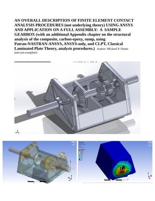
  • 9. Fig. 1- Solidworks model of gearbox. Exploded view shown. Fig. 2- Workbench model of gearbox after importing parasolids model from Solidworks.
  • 10. Fig. 3- Workbench model showing.preliminary maximum principal strain results from one proof load case. Fig. 4- ANSYS Classic model showing .same results as the image from the (previous image) Workbench model to show the viability of inputting file from Workbench into Classic..