Cs 1 du-09
•
0 likes•79 views

Bộ hội thảo trung tâm giá rẻ mà tốt trên thị trường được Âm Thanh AHK phân phối với giá rẻ nhất

Recommended
More Related Content
What's hot
What's hot (15)
Similar to Cs 1 du-09
Similar to Cs 1 du-09 (20)
Recently uploaded
Recently uploaded (19)
Cs 1 du-09
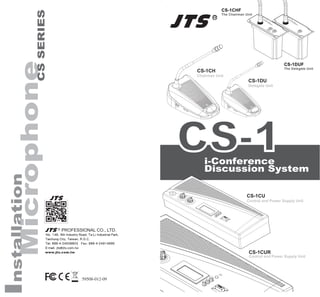
- 1. 59508-012-09 PROFESSIONAL CO., LTD. No. 148, 9th Industry Road, Ta-Li Industrial Park, Taichung City, Taiwan, R.O.C. Tel: 886-4-24938803 Fax: 886-4-24914890 E-mail: jts@jts.com.tw www.jts.com.tw CS-1CHF The Chairman Unit CS-1DUF The Delegate Unit
- 3. 1.Important Cautions 2.Features 3.Specification 3.1 Control and power supply unit (CU) 3.2 Delegate and Chairman unit 4.Preparing Procedure 4.1 Connecting between the delegate and chairman units 4.2 Connecting up to 150 unit 4.3 Connecting an external microphone 4.4 Connecting a wireless microphone 4.5 External recording and playing 4.6 Connecting a PA-system | other external equipment 4.7 Connecting a telephone coupler 4.8 Connecting Equalizer or other effects 4.9 Connecting power cord 5. Operation 5.1 System testing 5.2 Date / time setting 5.3 Key Lock 5.4 Counter operation 5.5 Delegate unit operation 5.6 Chairman unit operation 5.7 Volume control of the delegate and chairman units 5.8 Volume control of headphone and internal speaker of CU 5.9 Using a headphone 5.10 Open mode 5.11 Time mode 5.12 Override mode 5.13 Chairman only mode 5.14 Built-in recording 6. Technical Data 6.1 Electrical and Electro-Acoustical Characteristics 6.2 Mechanical Specifications 6.3 General Specifications 6.4 Pin configuration 1 2 3 6 10 11 11 12 12 13 14 14 15 15 16 16 17 17 18 18 19 19 20 20 21 21 22 23 24 24 25
- 4. 1 1.Important Cautions • Make all connections before plugging the unit into an AC power outlet. • Do not leave the devices in a place with high tempera- ture or high humility. • Do not handle the power cord with wet hands. • Keep the devices away from fire and heat sources. • Hot swapping is forbidden.
- 5. 2 2. Features The innovative CS-1 i-Conference Discussion System is equipped with JTS in-house made ECM capsule, intelligent automatic mixing technology and integrated acoustic and mechanical design, providing Turn-Key solution and delivering consistently natural, feedback- free audio performance with any environment. CS- 1CUR with built-in MP3 recording function can perform live recording during the conference according to the demand. The i-Conference Discussion System is ideal for discussion and meeting with up-to 150 attendants. A CS-1 i-Conference Discussion System consists of: • One Control and power supply unit (CU) • Maximum 50 delegate or chairman units • Peripheral audio and/or telecommunication equipment. The CU is the center of the discussion system which controls the microphones of the chairman and del- egate units as well as connects to other audio input and output. It also supplies the power for the CU itself, and up to 50 chairman and delegate units. The delegate unit enables the attendants to participate in a discussion by speaking through a microphone, controlled by a microphone ON/OFF push-button, and listening discussion by the internal loudspeaker and external headphone. The chairman unit not only provides the same function as the delegate unit, but also supports the addition of a “Priority button”,that enables the chairman to control the discussion by temporary or permanently over- riding and deactivating all active microphones of the delegate units.
- 6. 3 3. Specification 3.1 Control and power supply unit (CU) 3.1.1 Front Panel 1) Power On/Off switch 2) LCD display: setting and displaying mode status, simultaneously maximum user number, and date. 3) Set button: pressing “set” button to enter setting mode on the LCD panel. 4) Up & Down buttons: pressing “Up” or “Down” to switch the setting. 5) Speaker Volume control: controlling all connected chairman and delegate units. 6) Monitor Volume control: controlling both speaker and headphone of the CU. 7) Headphone input: allowing another alternative of listening discussion. While inserting the head- phone, the loudspeaker will be deactivated. 8) Loudspeaker. 9) REC(only for CS-1CUR model): When the record- ing pilot light is under the status of continuous green light on, press REC recording button to enter recording mode. The recording pilot light will then turn into continuous red light on to show it is under the status of recording. If you would like to stop re- cording, long press that button. When the pilot light appears cross-flashing between red light and green light and return back to continuous green light on, the recording is completed.
- 7. 4 10 9 *CS-1CUR 10) The description of the signal of recording pilot light is as below:(only for CS-1CUR model) a. Light is off: USB fails to be inserted or is unable to be detected b. Cross-flashing between red light and green light: USB flash drive is just inserted in and it shows USB is under the status of preparation. c. Green light: It represents the completion of USB preparation and press the recording button to start recording. d. Red light: It represents under the status of record- ing. e. Red light flashes slowly: USB capacity is lower than 20MB, reminding the user to replace the USB flash drive. f. Red light flashes rapidly: USB capacity is lower than 10MB and the recording will be terminated at any time.
- 8. 5 3.1.2 Rear Panel 1) VAC input: 2) Insertion input and output switch: default setting is “In”, when switching to“In”, all internal speaker will be muted, and switch to external audio device. 3) Telephone coupler input and output: 4) Insertion input and output: connect to an external audio equalizer for speech quality improvement. 5) Recorder input and output: connect to a recorder thatcould record and play back the discussion. 6) Line input and output: connect to PA-System or other audio devices. 7) Gain control 1: control the volume level of Record- ing input. 8) Gain control 2: control the volume level of Micro- phone XLR input. 9) Trunk output 1 and 2: connect to chairman and delegate units. * 10) Microphone XLR input: connect to external micr phone or wireless microphone receiver. 11) USB input port: It is only for inserting USB drive to save the MP3 recording file when the record- ing is activated. It is compatible with USB drive of USB3.0/USB2.0. * Note: Hot swapping is forbidden. *CS-1CUR 11
- 9. 6 3.1.3 LCD Display 1) Mode status: show the discussion mode 2) Simultaneously user number: the maximum num- ber of simultaneously active users is four. 3) Date | Set: While setting, “Set” will flash. 4) Time: 3.2 Delegate and Chairman unit 3.2.1 CS-1CH/DU: 1) Gooseneck Microphone 2) Two 3.5mm stereo headphone sockets 3) Rotary volume control: control the volume level of the headphone. 4) Ring & Microphone “On” indicator: While micro- phone is activated, both indicators will light up. 5) Loudspeaker (CS-1CH/DU) 6) 7-pole circular female socket * 7) 7 pole circular male connection cable 8) Microphone ON/OFF push-button 9) Chairman Priority button 10) Priority button setting switch: The default setting is“A”, meaning when releasing the priority button, the microphone on delegate units will be re- activated. When switching to “B”, the microphone on delegate units won’t be reactivated after the priority button is released. 11) Gooseneck Microphone Gain Control: Control the volume of the microphones on the chairman and delegate units. * Note: Hot swapping is forbidden. A B
- 11. 8 3.2.2 Embedded Conference Unit:CS-1CHF and CS-1DUF This discussion unit can be installed on the desktop or embedded into the system. Embedded conference unit installation procedures: a.) Cut a hole in the desktop the size (unit: mm) as shown in the figure below; b.) As presented in the figure, drill two 3mm screw holes; the distance between the centers of the two holes should be 102mm apart. c.) Adjust the two cable cords on the back of the dis- cussion unit, in order to secure the setup. d.) Then place the discussion unit in the hole and se- cure it with the screws. After it’s securely fixed into position, place the nameplate on. Cutting Hole and Drilling Hole Size Diagram
- 12. 9 Embedding Installation Diagram 0.6m 7P-DIN standard plug cable (female plug x1): connect it to the next discussion unit or to the terminal connector. 1.5m 7P-DIN standard plug cable (male plug x1): connect it to the last discus- sion unit’s main control or the main control’s extension output. Gooseneck Microphone Ring “ON” indicator, While microphone is actived. Gooseneck microphone socket Microphone ON/ OFF push-button Chairman Priority button 2 3 5 4 6
- 13. 10 4. Preparing Procedure 4.1 Connecting between the delegate and chairman units 1) Insert 7-pole circular male connection cable of the chairman or delegate units into the Trunk socket on the CU. 2) Connect the second unit to 7-pole circular female socket of the first unit. 3) Repeat the above actions for the rest of units. (Maximum connected number per trunk socket is 25) Gooseneck Microphone Gain Control: Control the volume of the microphones on the chairman and delegate units. Priority button setting switch: The default setting is“OFF”, meaning when releasing the priority button, the microphone on delegate units will be re-activated. When switching to “ON”, the mi- crophone on delegate units won’t be reactivated after the priority button is released. CHIME: When the CS-1CHF Priority is pressed, the CS-1CU or Audio output will send out a signal. 3...25 3...25 *CS-1CU 7 8 9
- 14. 11 *CS-1CU male male fenale fenale male male ...*3...25 ...*3...25 CS-1CHF CS-1DUF 4.3 Connecting an external microphone 1) Put the external microphone connector into the microphone XLR input of the CU. 2) Adjust the sensitivity by using the gain control 2. 4.2 Connecting up to 150 units:CS-1CH / DU or CS-1CHF / DUF The i-Conference discussion system can be used with up to 150 units by adding maximum 2 additional CUs functioning as power supply units only. The system is controlled by the master CS-1 CU. The cables neces- sary for these connections can be delivered by your local dealer. 4) Connect the second unit to 7-pole circular connec- tion Cable. *CS-1CU
- 15. 12 Caution: Always use the microphone with balanced output. The microphone XLR input provides a 12V phantom power supply. 4.4 Connecting a wireless microphone 1) Connect a wireless receiver to the microphone XLR input of CU. 2) Adjust the sensitivity by using the gain control 1 *CS-1CU *CS-1CU 4.5 External recording and playing 1) Connect a recorder to the recorder input and output by two pairs of RCA cable. 2) Adjust the sensitivity by using the gain control 1
- 16. 13 4.5.1 Built-in recording (only for CS-1CUR model) 1) Insert USB drive on the back panel 2) Pres the recording button on the panel if recording is required to activate the recording. Long press the recording button during the process of recording to end the recording. outin *CS-1CUR *CS-1CUR Recording button Recording pilot light 4.6 Connecting a PA-system | other external equipment 1) Connect audio sources to the line input by a RCA cable.
- 17. 14 4.7 Connecting a telephone coupler 1) Connect the telephone coupler to the telephone input and output of the CU by a pair of RCA cable. 2) The telephone coupler would further connect to the telephone wall socket and a telephone. Caution: Never try to connect a telephone directly to CS-1 i- Conference Discussion system. A telephone coupler could provide adequate isola- tion between the telephone network and the CS-1 i-Conference Discussion System. Telephone Coupler 2) Connect a PA-system or other devices to the line output by inout a RCA cable. out in audio sources PA-system 4.8 Connecting Equalizer or other effects 1) Connect a equalizer or other effects to the insertion input and output by one pairs of RCA cable. 2) When insertion input and output switches to “O/out, audio signal will be processed by effect equalizers that connected to insertion output and input.
- 18. 15 4.9 Connecting power cord 1) Using the supplied power cord set to connect the CU to the power supply socket. 2) Press Power ON/OFF switch to turn on the system. As soon as the power is on, the LCD Display will light up. Equalizer *CS-1CU *CS-1CU 5. Operation 5.1 System testing 1) Pressing the “Set” button over 1.5 seconds, the Date | Set area on the LCD Display will flash and show “Set”. 2) Press “Up” or “Down” button to choose “System Test” on the Mode Status area of the LCD Display.
- 19. 16 3) All connected chairman and delegate units will light up. 5.2 Date | Time Setting 1) Pressing the “Set” button over 1.5 seconds, the Date | Set area on the LCD Display will flash and show “Set”. 2) Press “Up” or “Down” button to choose “Set Date Time” on the Mode Status area of the LCD Display. 3) Press “Set”, The “Year” will flash, press “Up” or “Down” button to select. 4) Repeat the action 3) to set up “Month” ,“Date”, “Hour”, and “Minute. 5) Press the “Set” button to save the settings. 5.3 Key Lock 1) Pressing the “Set” button over 1.5 seconds, the Date | Set area on the LCD Display will flash and show “Set”. 2) Press “Up” or “Down” button to choose “KeyLock” on the Mode Status area of the LCD Display. 3) All buttons will be deactivated. 4) Repeat above action again to unlock.. 3...25 SET SET *CS-1CU
- 20. 17 5.4 Counter Operation 1) Pressing the “Set” button, the Date | Set area on the LEDDisplay will show“Counter” 2) Pressing “Up” to start counting. 3) Pressing “Up” again to stop. 4) Pressing “Down” to clear data after stopping. 5) Pressing the “Set” button again to jump back the original display. Notice that you can operate any other functions of the control unit when the counter is used. 5.5 Delegate unit operation 1) Depending on the setting of the microphone mode on the CU, pressing the microphone ON/OFF (CS- 1DUF:Talk) push-button will activate the gooseneck microphone. 2) Pressing again turns the microphone off SET SET SET CS-1DUF 1..4 1..4
- 21. 18 5.6 Chairman unit operation 1) Independent of the setting of the microphone mode on the CU, pressing the microphone ON/OFF(CS- 1CHF:Talk)” push-button will activate the goose- neck microphone on the chairman unit. 2) Pressing again turns the microphone off. 3) Pressing and holding the chairman priority button will deactivate all active delegate units and activate the chairman microphone. 4) Releasing the button will activate them again. 5.7 Volume control of the delegate and chairman units (CS-1CH/DU) 1) Turning the speaker volume control to adjust the volume of the loudspeakers of the delegate and chairman units. 2) In the fully counterclockwise position, all loud- speakers will be muted. 1 2 3 4 5 6 7 8 9 100 1 2 3 4 5 6 7 8 9 100 1 2 3 4 5 6 7 8 9 100 *CS-1CU CS-1CHF Delegate Priority button Delegate Chairman Chairman
- 22. 19 5.8 Volume control of headphone (CS-1CH/DU) and internal speaker of CU 1) While using internal speaker or headphone to monitor the discussion, turning the monitor volume control to adjust the volume of them. 2) The maximum volume level is controlled by the speaker volume control of CU 5.9 Using a headphone (CS-1CH/DU) 1) Connecting the headphones to the left and/or right side of the units. 2) Inserting a headphone jack will mute the loud- speaker. 3) Adjusting the volume of the headphones by using the rotary volume control. 4) The maximum volume level depends on the level of the speaker volume control on the CU. 1 2 3 4 5 6 7 8 9 100*CS-1CU *CS-1CU
- 23. 20 5.10 Open mode 1) Pressing the “Set” button over 1.5 seconds, the Date | Set area on the LCD Display will flash and show “Set”. 2) Press “Up” or “Down” button to choose “Open Mode” on the Mode Status area of the LCD Display. 3) Press “Set” button again, the number on simultane- ously user number will flash. 4) Press “Up” or “Down” button to choose the simulta- neously user number (1,2,3,4). 5) Press “Set” button to save the changes. Under “Open mode”, press the microphone ON/ OFF push-button on chairman and delegate units will activate the microphone. Press again will deactivate it. 5.11 Time mode 1) Selecting the “Time mode” and simultaneously maximum user number as the 5.10 procedures. Under “Time mode”, press the microphone ON/ OFF push-button on delegate units will activate the microphone for 30 seconds. If the number of active delegate units is smaller than the maximum user number, press again will activate it for another 30 seconds. 1..4 1..4 SET SET 1..4 1..4 SET SET
- 24. 21 5.12 Override mode 1) Selecting the “Override mode” as the 5.10 proce- dures. Under “Override mode”, the system only allow one delegate unit be activated. Press the microphone ON/ OFF push-button on one delegate unit will deactivate the previous active delegate unit, and activate its own microphone 5.13 Chairman only mode 1) Selecting the “Chairman only mode” as the 5.10 proc dures. Under “Chairman only mode”, the system only allow chairman units be activated. All delegate units will be deactivated. A A B A B SET SET A B
- 25. 22 5.14 Built-in recording 1) Insert USB drive on the back panel 2) The recording pilot light on the panel showing cross- flashing between red light and green light repre- sents USB drive is under the status of preparation. 3) The recording pilot light will show green light when USB preparation is completed and press recording button to start recording. 4) When press the recording button and the recording pilot light shows red light, it enters recording mode. 5) To end recording, press and hold the recording but- ton and wait the light signal showing cross-flashing between red light and green light before releas- ing the releasing button and the recording will be terminated. PS: When the red light flashes slowly during the recording process, it represents the USB capacity is lower than 20MB to remind the user to replace USB drive. When the red light turns into rapid flashing, it represents the USB capacity is lower than 10MB, and the recording will be terminated at any time. If the recording pilot light is not on, it represents USB is not inserted or unable to be detected. *CS-1CUR *CS-1CUR Recording button Recording pilot light
- 26. 23 6. Technical Data 6.1 Electrical and Electro-Acoustical Characteristics 6.1.1 CS-1CU Voltage: VAC100-240~, 50/60Hz Current consumption: MAX 1.0A(100VAC) 0.42A(240VAC) DC supply to contribution units: +15V, -7.5V Line, telephone coupler and insertion in/outputs (unbal- anced) • Input sensitivity: -14dBV/+11dBV (hominal/maximum) • Input impedance: 33KΩ • Output level: -14dBV/+11dBV (hominal/maximum) • Output impedance: 500Ω Recorder in/output (unbalanced) • Input sensitivity: -20dBV/+5dBV (hominal/maximum) • Input impedance: 47KΩ (for L & R channel) • Adjustment: -20dBV/+5dBV • Output level: +0/-30dB • Output impedance: 500Ω Recording function (only for CS-1CUR model) •Storage medium: USB3.0 32GByte USB (downward compatible) •Recording format: MP3 •Maximum recording time: more than 240 hours (32GByte USB drive) •Operational interface: Single-button recording activation, LED indicating recording status, no displaying function External microphone input (balanced) • Input sensitivity: -56dBV (-6dBV via mcludod adapter) • Adjustment: +6dBV/-6dB • Phantom supply: 12V+/-1V, 2*680Ω (+/-2%) Headphone output • Output level: -8dBV/+2dBV • Output Impedance: 22Ω
- 27. 24 System limits Number of delegate/chairman units connected to CU • Maximum in total: 50 • Maximum per Trunk output: 25 (<50M) • Maximum trunk length using CS-1: standard cabling: 100m (328 ft) 6.1.2 CS-1CH(CHF) & DU(DUF) Gooseneck Microphone: • Type: Back Electret Condenser • Frequency Response: 50 to 18,000Hz • Polar Pattern: Cardioid • Max. SPL for 1% THD: 125dB • Gooseneck Length: 15” (400mm) 6.2 Mechanical Specifications 6.2.1 CS-1CU Dimensions (HxWxD) : 360*150*90 mm Weight : 1745g 6.2.2 CS-1CH & DU Dimensions (HxWxD) without mic. : 170*115*65 mm Length of mic. : 400 mm Weight : 1100g 6.2.3 CS-1CHF & DUF Dimensions (HxWxD) without mic. : 85*111.5*45 mm Length of mic. : 422 mm Weight : 352g (Gooseneck included) 6.3 General Specifications Environmental Conditions Temperature range Storage and transport: -20 to 70℃ (-4 to+158℉) Operational: +5 to 45℃ (+41 to+113℉) Ambient humidity Storage and transport: 0%-99% RH Operational: 20%-95% RH Air pressure: 600mBar-11000mBar Safety: EN60065
- 28. 25 6.4 Pin configuration Trunk Connections 1) Audio contribution line 2) GND 3) Audio distribution line 4) Control line 1 5) Control line 2 6) V+ supply 7) V- supply External Microphone (XLR) 1) GND (0V, phantom supply) 2) Signal + (+12V, Phantom supply) 3) Signal – (+12V, Phantom supply) CINCH Connector 1) Signal + 2) Signal - Power Connector 1) Mains 2) Earth 3) Mains Headphone Jack-Plug (3.5mm) 1) Tip (Signal +) 2) Ring (Signal -) 3) Sleeve (Electrical earth/screen) RQP Headphone Jack-Plug (3.5mm) *CS-1CU *CS-1CU