This document describes an NVIS-compatible caution warning panel that features 32 LED annunciators, 52 configurable panel options, and operates in a wide temperature range from -55°C to +70°C. It provides 28V DC power and has a wide viewing angle of ±45° horizontally and vertically. The panel can be customized with different annunciator configurations for various aviation platforms.
Caution Warning Panel Data Sheet (Interface Displays)
1. 4630 North Avenue Oceanside CA 92056 760.945.0230 www.interfacedisplays.com
Data Sheet
ds_CWPNVIS_
20400-xx.pdf
Page 1 of 2
Nov-18-15
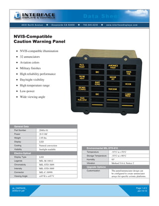
NVIS-compatible illumination
32 annunciators
52 annunciator panel
configurations available
Aviation colors
Military finishes
High reliability performance
Day/night visibility
High temperature range
Low-power
Wide viewing angle
NVIS-Compatible
Caution Warning Panel
General Data
National Stock
Number (NSN)
6340-01-632-3531
(for baseline F-16 CWP;
additional NSNs are assigned to
annunciator panels and other components)
Part Number 20400-xx
Power 28 V DC
Weight 2.95 lbs
Display LED
Cooling Natural convection
Visibility Sunlight readable
Electro-Optical
Display Type LED
Legends MIL-M-18012
Chromaticity MIL-STD-3009
Intensity MIL-STD-3009
Connector MIL-C-38999
Viewing Angle ±45°H x ±45°V
Environmental MIL-STD-810
Temperature -55°C to +70°C
Storage Temperature -55°C to +90°C
Humidity 95°
Vibration Method 514.4, Notice 2
Upgrade Options
Customization The annunciator panel design can
be configured to create annunciator
arrays for specific avionic platforms.
52 annunciator panel configurations
are currently available.
2. 4630 North Avenue Oceanside CA 92056 760.945.0230 www.interfacedisplays.com
J1 Pin # Function
1 Unused
2 +28 VDC Test Input
3 +28 VDC Input to Position 24
4 +28 VDC Input to Position 15
5 +28 VDC Input to Position 10
6 +28 VDC Input to Position 3
7 Master Caution Output
8 +28 VDC Input to Position 17
9 +28 VDC Input to Position 20
10 +28 VDC Input to Position 23
11 +28 VDC Input to Position 5
12 +28 VDC Input to Position 8
13 +28 VDC Input to Position 11
14 +28 VDC Input to Position 13
15 +28 VDC Input to Position 16
16 +28 VDC Input to Position 19
17 +28 VDC Input to Position 22
18 +28 VDC Input to Position 2
19 +28 VDC Input to Position 14
20 Dim/Bright Control
21 Master Caution Reset
22 +28 VDC Input to Position 4
23 +28 VDC Input to Position 1
24 +28 VDC Input to Position 21
25 +28 VDC Input to Position 18
26 +28 VDC Input to Position 12
27 +28 VDC Input to Position 9
28 +28 VDC Input to Position 7
29 +28 VDC Input to Position 6
30 Ground
31 +28 VDC Power Input
32 +28 VDC Input to Position 25
33 +28 VDC Input to Position 26
34 +28 VDC Input to Position 27
35 +28 VDC Input to Position 28
36 +28 VDC Input to Position 29
37 +28 VDC Input to Position 30
38 +28 VDC Input to Position 31
39 +28 VDC Input to Position 32
40 Unused
41 Unused
ds_CWPNVIS_
20400-xx.pdf
Page 2 of 2
Nov-18-15
Data Sheet
(A)
(A)
(A)
(A)
(A)
(A)
(A)
(A)
(A)
(A)
(A)
(A)
(A) (A)
(A)
(A)
(A)
(A)
(A)
(A)
(A)
(A)
(A)
(A) Dimensions available upon request.